EP1898103A2 - Hubzylinder mit Selbstverriegelung - Google Patents
Hubzylinder mit Selbstverriegelung Download PDFInfo
- Publication number
- EP1898103A2 EP1898103A2 EP07291000A EP07291000A EP1898103A2 EP 1898103 A2 EP1898103 A2 EP 1898103A2 EP 07291000 A EP07291000 A EP 07291000A EP 07291000 A EP07291000 A EP 07291000A EP 1898103 A2 EP1898103 A2 EP 1898103A2
- Authority
- EP
- European Patent Office
- Prior art keywords
- piston
- cylinder
- wall
- pressure
- hydraulic
- Prior art date
- Legal status (The legal status is an assumption and is not a legal conclusion. Google has not performed a legal analysis and makes no representation as to the accuracy of the status listed.)
- Withdrawn
Links
Images

Classifications
-
- F—MECHANICAL ENGINEERING; LIGHTING; HEATING; WEAPONS; BLASTING
- F15—FLUID-PRESSURE ACTUATORS; HYDRAULICS OR PNEUMATICS IN GENERAL
- F15B—SYSTEMS ACTING BY MEANS OF FLUIDS IN GENERAL; FLUID-PRESSURE ACTUATORS, e.g. SERVOMOTORS; DETAILS OF FLUID-PRESSURE SYSTEMS, NOT OTHERWISE PROVIDED FOR
- F15B15/00—Fluid-actuated devices for displacing a member from one position to another; Gearing associated therewith
- F15B15/20—Other details, e.g. assembly with regulating devices
- F15B15/26—Locking mechanisms
- F15B15/262—Locking mechanisms using friction, e.g. brake pads
Definitions
- the present invention relates to a hydraulic cylinder provided with means for locking it at any point of its stroke.
- the known mechanical locking means are expensive and complex.
- the present invention solves the problem of locking a hydraulic cylinder, whatever its position and that as long as necessary.
- the object of the present invention is to provide a jack which is permanently locked and which is unlocked only on command.
- This jack is of the type in which the locking of the piston is obtained by elastic deformation either of the inner wall of the cylinder or of the outer wall of the piston, so as to obtain the tightening of one on the other, and is characterized by the fact that the locking is permanently obtained by means of a pressure, which causes the elastic deformation of the inner wall of the cylinder or the outer wall of the piston; the unlocking of said jack being obtained by canceling this permanent deformation.
- the locking is permanently obtained by the elastic deformation of the cylinder or the piston under the effect of a sealed chamber, permanently filled with a neutral gas under pressure; the unlocking being obtained by a hydraulic pressure which is interposed between the piston and the cylinder so as to exert a counter-pressure counter-pressure which cancels the elastic deformation caused by the neutral gas under pressure.
- the locking is permanently obtained by elastic deformation of the outer wall of the piston under the effect of a hydraulic pressure exerted permanently by a battery, arranged inside. of the piston, the action of this accumulator being suppressed by a mechanical control, which cancels the elastic deformation of the wall of the piston.
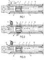
- the hydraulic cylinder comprises a piston 1 which moves in a cylinder consisting of two coaxial tubes 2 and 3, which provide a space between them cylindrical ring 4.
- Said annular space 4 is connected to a pressurized gas source 6 through a non-return valve 7; so that the chamber 4 is a closed, sealed volume, the pressure of the gas being permanent.
- the deformation of the inner tube 2 is a function of the thickness of the wall of this tube, the metal used and the pressure of the gas blown into the space 4. These parameters are determined according to the use for which the jack is intended .
- the importance of the locking force of the piston 1 is a function of the pressure of the gas and the importance of the surfaces in contact. These parameters will also be determined according to the use for which the cylinder is intended.
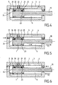
- Figures 4 to 6 relate to an alternative embodiment of the self-locking cylinder.
- the piston 1 carries at each of its ends 25-26 sealing segments similar to the segments used in internal combustion engines.
- sealing segments 25 and 26 are formed two annular grooves 20 and 21, which are connected to each other by a conduit 22, which communicates with the chambers 8 and 9 of the cylinder by the valves -return 23 and 24 in reversed positions.
- the cylindrical annular chamber 4 which is permanently filled with a neutral gas (nitrogen) under pressure, causes the elastic deformation of the inner tube 2, whose wall is relatively thin and deformable.
- the piston 1 is then jammed by the tightening exerted by the pressure of the gas and can no longer move.
- the chamber 8 is fed with hydraulic fluid under pressure through the pipe Pa.
- This liquid pushes back the non-return valve 24 and through the pipe 22 feeds the grooves 20 and 21, which allows the counter-pressure against set up all around the piston 1, to cancel the effect of the gas pressure included in the chamber 4; so that the piston 1 is unlocked and can move in the direction D1.
- the sealing segments 25 and 26 allow one and the other a slight leak at the beginning of pressurization: this leak, adding to the introduction of liquid under pressure by the grooves 20 and 21, facilitates the appearance of a film of oil under pressure between the wall of the piston 1 and that of the tube 2.
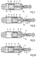
- FIGS. 7 to 10 show another embodiment of the invention which operates in an inverse manner, that is to say that it is no longer the cylinder which presses the piston by retracting elastically but the piston which comes to tighten against the wall of the cylinder by expanding.
- Figure 7 illustrates a first locking position of the jack.
- the piston 30, carried by a rod 31, can slide in a cylinder 32.
- the piston is hollow and comprises a chamber 33 filled with a neutral gas under pressure.
- the wall 30a surrounding the chamber 33 is relatively thin and deformable: under the effect of the pressure of the gas in the chamber 33, the wall 30a deforms and is pressed against the inner wall of the cylinder 32; so that the piston is blocked.
- FIG. 8 shows that pressurized hydraulic fluid has been introduced into the chamber 34.
- This hydraulic fluid under pressure is interposed between the wall 30a of the piston 30 and the inner wall of the cylinder 32, creating an antagonistic back pressure which cancels the deformation of said wall 30a, which releases the piston 30 which can move along the arrow f1.
- the hydraulic pressure is introduced into the small chamber 35.
- the hydraulic fluid under pressure is interposed between the wall 30a of the piston 30 and the inner wall of the cylinder 32, creating an antagonistic counter-pressure which cancels the deformation of the said wall 30a, which releases the piston 30 which can move along the arrow f2.
- the chambers 4 or 33 are sealed, permanently pressurized volumes, but a check valve can also be provided. as the valve 7 of Figures 2 and 3 or have one in the pipe 33a, located in the piston rod to cancel the pressure of the gas.
- This type of cylinder will be used in all cases where a cylinder must maintain a load without changing position and this for a very long time.
- such a cylinder can be advantageously used for positioning a mobile radar; so that once the radar is set, its position is kept constant.
- the blocking of the piston is obtained by the fact that the chamber filled with gas is tight and permanently filled with gas under pressure; but it is obvious that one can obtain the unlocking either by canceling the gas pressure by a suitable valve, or by replacing the gas pressure by a gas pressure or variable and controlled fluid.
- Figures 11 and 12 illustrate a third embodiment of the invention.
- the jack is constituted by a cylinder 20, in which slides a piston 21 integral with a rod 22.
- the piston 21 comprises an annular chamber 23 whose annular wall 24, in contact with the inner wall of the cylinder 20 is elastically deformable.
- This annular chamber 23 is in communication with the chamber 25 of an accumulator 26, disposed inside the piston 21.
- a mechanical means consisting of a rod 27 sliding inside the rod 22 of the piston 21 can push the movable member of the accumulator 26 against its spring 29.
- this rod 27 can be caused by any appropriate device; but, in the example shown it is caused by a small piston 28, secured to the rod 27, hydraulically controlled.
Landscapes
- Engineering & Computer Science (AREA)
- Physics & Mathematics (AREA)
- Fluid Mechanics (AREA)
- Mechanical Engineering (AREA)
- General Engineering & Computer Science (AREA)
- Actuator (AREA)
- Braking Arrangements (AREA)
Applications Claiming Priority (1)
| Application Number | Priority Date | Filing Date | Title |
|---|---|---|---|
| FR0607819A FR2905428A1 (fr) | 2006-09-06 | 2006-09-06 | Verin hydraulique a verrouillage automatique |
Publications (2)
| Publication Number | Publication Date |
|---|---|
| EP1898103A2 true EP1898103A2 (de) | 2008-03-12 |
| EP1898103A3 EP1898103A3 (de) | 2008-07-02 |
Family
ID=37876016
Family Applications (1)
| Application Number | Title | Priority Date | Filing Date |
|---|---|---|---|
| EP07291000A Withdrawn EP1898103A3 (de) | 2006-09-06 | 2007-08-10 | Hubzylinder mit Selbstverriegelung |
Country Status (3)
| Country | Link |
|---|---|
| US (1) | US7779745B2 (de) |
| EP (1) | EP1898103A3 (de) |
| FR (1) | FR2905428A1 (de) |
Cited By (2)
| Publication number | Priority date | Publication date | Assignee | Title |
|---|---|---|---|---|
| CN102979784A (zh) * | 2012-12-10 | 2013-03-20 | 沈阳工业大学 | 一种液压锁紧机构 |
| WO2014177774A1 (fr) * | 2013-04-30 | 2014-11-06 | Douce Hydro | Systeme de blocage de deux pieces en mouvement de translation l'une par rapport a l'autre |
Families Citing this family (8)
| Publication number | Priority date | Publication date | Assignee | Title |
|---|---|---|---|---|
| US8523145B2 (en) * | 2009-04-02 | 2013-09-03 | Actuant Corporation | Jack assembly with integrated pressure relief assembly |
| US9127661B2 (en) * | 2010-10-25 | 2015-09-08 | Hamilton Sundstrand Corporation | Bootstrap accumulator system with telescoping actuator cylinder |
| CN104214165B (zh) * | 2014-04-25 | 2016-04-13 | 东南大学 | 一种双端口支撑锁紧油缸及其控制方法 |
| DE102015101570B4 (de) * | 2015-02-04 | 2019-04-25 | Kraussmaffei Technologies Gmbh | Schließeinheit einer Säulen aufweisenden Spritzgießmaschine |
| CN204607490U (zh) * | 2015-03-04 | 2015-09-02 | 杭州盈江机械制造有限公司 | 负载快速起升的液压千斤顶 |
| DE102016119636B3 (de) * | 2016-10-14 | 2018-02-08 | Carl Zeiss Smart Optics Gmbh | Abformwerkzeug und Verwendung desselben |
| CN109534211B (zh) * | 2019-01-24 | 2023-10-27 | 长江水利委员会长江科学院 | 一种柔性千斤顶 |
| KR102370177B1 (ko) * | 2019-11-07 | 2022-03-04 | 서문원 | 브레이킹 시스템을 갖는 높이 조절용 유압실린더 장치 및 이를 이용한 주방용 가구 |
Citations (5)
| Publication number | Priority date | Publication date | Assignee | Title |
|---|---|---|---|---|
| FR2196877A1 (de) | 1972-08-03 | 1974-03-22 | Spenklin Ltd | |
| DE3113894A1 (de) | 1981-04-07 | 1982-11-11 | H. Kuhnke Gmbh Kg, 2427 Malente | Druckmittelbetriebener arbeitszylinder |
| US5355707A (en) | 1991-08-14 | 1994-10-18 | Kabushiki Kaisha Kobe Seiko Sho | Rolling mill and method for operating rolling mill |
| US5957443A (en) | 1998-07-20 | 1999-09-28 | Vektek, Inc. | Hydraulic work support |
| EP1079117A1 (de) | 1999-02-24 | 2001-02-28 | Pascal Kabushiki Kaisha | Hydraulische verriegelungsvorrichtung |
Family Cites Families (3)
| Publication number | Priority date | Publication date | Assignee | Title |
|---|---|---|---|---|
| GB570897A (en) * | 1943-10-22 | 1945-07-27 | Messier Aircraft Equipment Ltd | Improvements in or relating to hydraulic jacks |
| US3575087A (en) * | 1968-11-18 | 1971-04-13 | Lourdes Ind Inc | Locking cylinder |
| US3665812A (en) * | 1969-07-01 | 1972-05-30 | Chukyo Electric Co | Apparatus for controlling rectilinear motion |
-
2006
- 2006-09-06 FR FR0607819A patent/FR2905428A1/fr not_active Withdrawn
-
2007
- 2007-08-07 US US11/882,933 patent/US7779745B2/en not_active Expired - Fee Related
- 2007-08-10 EP EP07291000A patent/EP1898103A3/de not_active Withdrawn
Patent Citations (5)
| Publication number | Priority date | Publication date | Assignee | Title |
|---|---|---|---|---|
| FR2196877A1 (de) | 1972-08-03 | 1974-03-22 | Spenklin Ltd | |
| DE3113894A1 (de) | 1981-04-07 | 1982-11-11 | H. Kuhnke Gmbh Kg, 2427 Malente | Druckmittelbetriebener arbeitszylinder |
| US5355707A (en) | 1991-08-14 | 1994-10-18 | Kabushiki Kaisha Kobe Seiko Sho | Rolling mill and method for operating rolling mill |
| US5957443A (en) | 1998-07-20 | 1999-09-28 | Vektek, Inc. | Hydraulic work support |
| EP1079117A1 (de) | 1999-02-24 | 2001-02-28 | Pascal Kabushiki Kaisha | Hydraulische verriegelungsvorrichtung |
Cited By (4)
| Publication number | Priority date | Publication date | Assignee | Title |
|---|---|---|---|---|
| CN102979784A (zh) * | 2012-12-10 | 2013-03-20 | 沈阳工业大学 | 一种液压锁紧机构 |
| CN102979784B (zh) * | 2012-12-10 | 2016-05-25 | 沈阳工业大学 | 一种液压锁紧机构 |
| WO2014177774A1 (fr) * | 2013-04-30 | 2014-11-06 | Douce Hydro | Systeme de blocage de deux pieces en mouvement de translation l'une par rapport a l'autre |
| US9976578B2 (en) | 2013-04-30 | 2018-05-22 | Douce Hydro | System for blocking relative translational movement between two parts |
Also Published As
| Publication number | Publication date |
|---|---|
| US20080054239A1 (en) | 2008-03-06 |
| US7779745B2 (en) | 2010-08-24 |
| FR2905428A1 (fr) | 2008-03-07 |
| EP1898103A3 (de) | 2008-07-02 |
Similar Documents
| Publication | Publication Date | Title |
|---|---|---|
| EP1898103A2 (de) | Hubzylinder mit Selbstverriegelung | |
| EP2591273B1 (de) | Befüllungsanschluss, entsprechender behälter und entsprechendes befüllungsverfahren | |
| EP2737234B1 (de) | Füllanschluss, behälter, füllverfahren und fülldüse | |
| EP3265716B1 (de) | Ventil, behälter und verfahren zum füllen, extrahieren und abführen | |
| FR2546265A1 (fr) | Raccord de tuyauteries | |
| EP2394080B1 (de) | Vorrichtung zur selektiven blockierung eines durchflusses | |
| FR2704924A1 (fr) | Vanne pyrotechnique. | |
| LU87748A1 (fr) | Dispositif de neutralisation d'une soupape de pression residuelle d'une bouteille a gaz | |
| EP0239451A1 (de) | Rückschlagventil, insbesondere für Druckwasserreaktor | |
| FR2731071A1 (fr) | Indicateur de pression differentielle | |
| FR2674042A1 (fr) | Dispositif hydraulique et pneumatique de blocage. | |
| CA1267644A (fr) | Actionneur a accumulateur d'energie pneumatique notamment pour robinet | |
| EP1092093B1 (de) | Membranpumpe und membran für diese pumpe | |
| FR3093781A1 (fr) | Robinet, récipient de fluide sous pression et procédés de remplissage et de soutirage. | |
| FR2779194A1 (fr) | Dispositif a fluide compressible | |
| EP3519322B1 (de) | Vorrichtung zur ausgabe eines unter druck stehenden materials | |
| FR3101125A1 (fr) | Dispositif de conditionnement, ensemble comprenant un tel dispositif et un récipient, son utilisation et un procédé de remplissage ou de soutirage | |
| EP2992224B1 (de) | System zur blockierung der relativen translationsbewegung zwischen zwei teilen | |
| WO2022189722A1 (fr) | Vanne de detente comportant un coulisseau mobile | |
| EP3708900A1 (de) | Unter druck stehender fluid-anschluss, hahn und behälter, der einen solchen anschluss umfasst, und anschlussverfahren | |
| FR2552514A1 (fr) | Amortisseur du type fluidique | |
| WO1997046442A1 (fr) | Compresseur hydraulique de ressort | |
| FR2578944A1 (fr) | Vanne de securite a piston flexible pour puits d'exploitation petroliere | |
| FR2938308A1 (fr) | Perfectionnements aux accumulateurs oleopneumatiques a piston | |
| FR2697606A1 (fr) | Soupape pour commander l'écoulement d'un fluide sous pression au travers de la section de passage entre deux conduits d'entrée et de sortie. |
Legal Events
| Date | Code | Title | Description |
|---|---|---|---|
| PUAI | Public reference made under article 153(3) epc to a published international application that has entered the european phase |
Free format text: ORIGINAL CODE: 0009012 |
|
| AK | Designated contracting states |
Kind code of ref document: A2 Designated state(s): AT BE BG CH CY CZ DE DK EE ES FI FR GB GR HU IE IS IT LI LT LU LV MC MT NL PL PT RO SE SI SK TR |
|
| AX | Request for extension of the european patent |
Extension state: AL BA HR MK YU |
|
| PUAL | Search report despatched |
Free format text: ORIGINAL CODE: 0009013 |
|
| AK | Designated contracting states |
Kind code of ref document: A3 Designated state(s): AT BE BG CH CY CZ DE DK EE ES FI FR GB GR HU IE IS IT LI LT LU LV MC MT NL PL PT RO SE SI SK TR |
|
| AX | Request for extension of the european patent |
Extension state: AL BA HR MK RS |
|
| 17P | Request for examination filed |
Effective date: 20080920 |
|
| AKX | Designation fees paid |
Designated state(s): AT BE BG CH CY CZ DE DK EE ES FI FR GB GR HU IE IS IT LI LT LU LV MC MT NL PL PT RO SE SI SK TR |
|
| GRAP | Despatch of communication of intention to grant a patent |
Free format text: ORIGINAL CODE: EPIDOSNIGR1 |
|
| STAA | Information on the status of an ep patent application or granted ep patent |
Free format text: STATUS: THE APPLICATION IS DEEMED TO BE WITHDRAWN |
|
| 18D | Application deemed to be withdrawn |
Effective date: 20130301 |