EP1898082B1 - Kraftstoffeinspritzventil und Verfahren zu dessen Montage - Google Patents
Kraftstoffeinspritzventil und Verfahren zu dessen Montage Download PDFInfo
- Publication number
- EP1898082B1 EP1898082B1 EP20060018804 EP06018804A EP1898082B1 EP 1898082 B1 EP1898082 B1 EP 1898082B1 EP 20060018804 EP20060018804 EP 20060018804 EP 06018804 A EP06018804 A EP 06018804A EP 1898082 B1 EP1898082 B1 EP 1898082B1
- Authority
- EP
- European Patent Office
- Prior art keywords
- valve body
- valve
- sealing element
- body shell
- outlet portion
- Prior art date
- Legal status (The legal status is an assumption and is not a legal conclusion. Google has not performed a legal analysis and makes no representation as to the accuracy of the status listed.)
- Ceased
Links
- 238000002347 injection Methods 0.000 title claims description 30
- 239000007924 injection Substances 0.000 title claims description 30
- 239000012530 fluid Substances 0.000 claims description 57
- 238000007789 sealing Methods 0.000 claims description 35
- 239000000463 material Substances 0.000 claims description 8
- 229920001971 elastomer Polymers 0.000 claims description 7
- 239000004033 plastic Substances 0.000 claims description 6
- 229920003023 plastic Polymers 0.000 claims description 6
- 239000005060 rubber Substances 0.000 claims description 6
- 230000008878 coupling Effects 0.000 claims description 4
- 238000010168 coupling process Methods 0.000 claims description 4
- 238000005859 coupling reaction Methods 0.000 claims description 4
- 239000002245 particle Substances 0.000 description 14
- 238000002485 combustion reaction Methods 0.000 description 7
- 238000000034 method Methods 0.000 description 7
- 229920002449 FKM Polymers 0.000 description 4
- 239000000446 fuel Substances 0.000 description 4
- 230000000694 effects Effects 0.000 description 2
- 239000000243 solution Substances 0.000 description 2
- 230000007423 decrease Effects 0.000 description 1
- 239000000806 elastomer Substances 0.000 description 1
- 229920002313 fluoropolymer Polymers 0.000 description 1
- 239000004811 fluoropolymer Substances 0.000 description 1
- 230000036316 preload Effects 0.000 description 1
- 239000000126 substance Substances 0.000 description 1
- 229920003051 synthetic elastomer Polymers 0.000 description 1
- 239000005061 synthetic rubber Substances 0.000 description 1
- 238000003466 welding Methods 0.000 description 1
Images

Classifications
-
- F—MECHANICAL ENGINEERING; LIGHTING; HEATING; WEAPONS; BLASTING
- F02—COMBUSTION ENGINES; HOT-GAS OR COMBUSTION-PRODUCT ENGINE PLANTS
- F02M—SUPPLYING COMBUSTION ENGINES IN GENERAL WITH COMBUSTIBLE MIXTURES OR CONSTITUENTS THEREOF
- F02M51/00—Fuel-injection apparatus characterised by being operated electrically
- F02M51/06—Injectors peculiar thereto with means directly operating the valve needle
- F02M51/061—Injectors peculiar thereto with means directly operating the valve needle using electromagnetic operating means
- F02M51/0625—Injectors peculiar thereto with means directly operating the valve needle using electromagnetic operating means characterised by arrangement of mobile armatures
- F02M51/0664—Injectors peculiar thereto with means directly operating the valve needle using electromagnetic operating means characterised by arrangement of mobile armatures having a cylindrically or partly cylindrically shaped armature, e.g. entering the winding; having a plate-shaped or undulated armature entering the winding
- F02M51/0671—Injectors peculiar thereto with means directly operating the valve needle using electromagnetic operating means characterised by arrangement of mobile armatures having a cylindrically or partly cylindrically shaped armature, e.g. entering the winding; having a plate-shaped or undulated armature entering the winding the armature having an elongated valve body attached thereto
-
- F—MECHANICAL ENGINEERING; LIGHTING; HEATING; WEAPONS; BLASTING
- F02—COMBUSTION ENGINES; HOT-GAS OR COMBUSTION-PRODUCT ENGINE PLANTS
- F02M—SUPPLYING COMBUSTION ENGINES IN GENERAL WITH COMBUSTIBLE MIXTURES OR CONSTITUENTS THEREOF
- F02M61/00—Fuel-injectors not provided for in groups F02M39/00 - F02M57/00 or F02M67/00
- F02M61/16—Details not provided for in, or of interest apart from, the apparatus of groups F02M61/02 - F02M61/14
- F02M61/168—Assembling; Disassembling; Manufacturing; Adjusting
-
- F—MECHANICAL ENGINEERING; LIGHTING; HEATING; WEAPONS; BLASTING
- F02—COMBUSTION ENGINES; HOT-GAS OR COMBUSTION-PRODUCT ENGINE PLANTS
- F02M—SUPPLYING COMBUSTION ENGINES IN GENERAL WITH COMBUSTIBLE MIXTURES OR CONSTITUENTS THEREOF
- F02M2200/00—Details of fuel-injection apparatus, not otherwise provided for
- F02M2200/16—Sealing of fuel injection apparatus not otherwise provided for
Definitions
- the invention relates to a valve assembly for an injection valve and an injection valve.
- Injection valves are in wide spread use, in particular for internal combustion engines where they may be arranged in order to dose the fluid into an intake manifold of the internal combustion engine or directly into the combustion chamber of a cylinder of the internal combustion engine.
- injection valves are manufactured in various forms in order to satisfy the various needs for the various combustion engines. Therefore, for example, their length, their diameter and also various elements of the injection valve being responsible for the way the fluid is dosed may vary in a wide range.
- injection valves may accommodate an actuator for actuating a needle of the injection valve, which may, for example, be an electromagnetic actuator or piezo electric actuator.
- the respective injection valve may be suited to dose fluids under very high pressures.
- the pressures may be in case of a gasoline engine, for example, in the range of up to 200 bar and in the case of diesel engines in the range of up to 2000 bar.
- US 5,201,341 discloses a fluid flow control valve with a valve assembly.
- the valve assembly includes a central longitudinal axis and comprises a valve body shell having a recess forming an inner surface of the valve body shell, a valve body being arranged in the recess of the valve body shell, the valve body comprising an outer surface with a mounting contact area facing the inner contact surface of the valve body shell and extending in axial direction, the valve body comprising a cavity with a fluid inlet portion and a fluid outlet portion, a valve needle being axially movable in the cavity, the valve needle preventing a fluid flow through the fluid outlet portion in a closing position and releasing the fluid flow through the fluid outlet portion in further positions.
- the valve assembly further comprises a sealing element which is arranged coaxially between the valve body and the valve body shell.
- the object of the invention is to create a valve assembly which is simply to be manufactured and which facilitates a reliable and precise function.
- a valve assembly for an injection valve including a central longitudinal axis, comprising a valve body shell having a recess forming an inner surface of the valve body shell, a valve body being arranged in the recess of the valve body shell, the valve body comprising an outer surface with a mounting contact area facing the inner contact surface of the valve body shell and extending in axial direction, the valve body comprising a cavity with a fluid inlet portion and a fluid outlet portion, a valve needle being axially movable in the cavity, the valve needle preventing a fluid flow through the fluid outlet portion in a closing position and releasing the fluid flow through the fluid outlet portion in further positions.
- the valve assembly further comprises a sealing element being arranged coaxially between the valve body and the valve body shell.
- the sealing element is arranged at an end of the mounting contact area, the end facing away from the fluid outlet portion, the sealing element thereby sealingly coupling the valve body to the valve body shell.
- the mounting contact area is the part of the outer surface of the valve body which can be in contact with the inner surface of the valve body shell during the operation of the injection valve as well as during the mounting of the injection valve.
- the mounting contact area can be formed in one part but it may also be interrupted by recesses and grooves and be formed in several parts.
- the sealing element between the valve body and the valve body shell can advantageously prevent a fluid flow between sections of the recess charged with particles and sections of the recess not charged with particles.
- the sealing element is arranged at an end of the mounting contact area, which is facing away from the fluid outlet portion, the section of the recess extending from the sealing element in axial direction away from the fluid outlet portion can be prevented from being charged with particles during the assembly process.
- valve body has a groove facing the valve body shell and the sealing element is arranged in the groove. This has the advantage that a fixed arrangement of the sealing element in the valve body is possible.
- the sealing element comprises a material being of plastics. This makes it possible to obtain good sealing properties of the sealing element and to avoid the appearance of particles in the cavity of the valve body with the fluid outlet portion generated during the assembly process
- the sealing element comprising a material being a rubber.
- Rubber is a plastic with a low elasticity module and allows a low-cost solution.
- the sealing element consists of viton (Registered Trade Mark). Viton is a synthetic rubber and a fluoropolymer elastomer which has a high stability against aggressive chemicals like fuels.
- the invention is distinguished by a fuel injector comprising a valve assembly with a sealing element.
- An injection valve 62 ( figure 1 ), that is in particular suitable for dosing fuel to an internal combustion engine, comprises an inlet tube 2, a housing 6 and a valve assembly 60.
- the valve assembly 60 comprises a valve body 4 with a cavity 8, which takes in a valve needle 10 comprising an armature 12.
- a recess 16 is provided which further extends to a recess 18 of the armature 12.
- a spring 14 is arranged in the recess 16 of the inlet tube 2 and/or the recess 18 of the armature 12. Preferably, it rests on a spring seat being formed by an anti-bounce disc 20. By this the spring 14 is mechanically coupled to the needle 10.
- An adjusting tube 22 is provided in the recess 16 of the inlet tube 2. The adjusting tube 22 forms a further seat for the spring 14 and is axially movable during the mounting process of the injection valve 62 in order to preload the spring 14 in a desired way.
- the injection nozzle 24 may be, for example, an injection hole. However, it may also be of some other type suitable for dosing fluid.
- the seat plate 26 may be made in one part with the valve body 4 or a separate part from the valve body 4. In addition to that a lower guide 28 for guiding the needle 10 is provided. Additionally, a swirl disc 30 is provided.
- the injection valve 62 is provided with an actuator unit that comprises preferably an electromagnetic actuator with a coil 36, which is preferably overmolded.
- a valve body shell 38, the armature 12 and the inlet tube 2 are forming an electromagnetic circuit.
- the actuator unit may, however, also comprise another type of actuator, which is known to a person skilled in the art for that purpose.
- Such an actuator may be, for example, a piezoelectric actuator.
- a fluid inlet portion 42 is provided in the valve body 4 which communicates with a fluid outlet portion 44 which is a part of the cavity 8 near the seat plate 26.
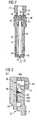
- the valve body shell 38 has a recess 40 with two sections, a chamber 40a and a gap 40b ( figure 3 ).
- the gap 40b is arranged in radial direction between the valve body shell 38 and the valve body 4.
- the chamber 40a is extending from the gap 40b in axial direction away from the fluid outlet portion 44 and is hydraulically coupled to the recess 18 of the armature 12 of the valve needle 10 by a channel 48.
- the recess 18 of the armature 12 of the valve needle 10 is hydraulically coupled to the cavity 8 by an opening 45 in the valve needle 10.
- a sealing element 46 is arranged coaxially between the valve body 4 and the valve body shell 38 thereby hydraulically separating the chamber 40a from the gap 40b.
- the sealing element is sealingly coupling the valve body 4 to the valve body shell 38. Consequently, a fluid flow from the gap 40b to the chamber 40a and vice versa is prevented.
- the valve body 4 has a groove 50 facing the valve body shell 38.
- the groove 50 is designed to receive the sealing element 46, thereby enabling the sealing element 46 to be fixed in the valve body 4.
- the sealing element 46 comprises a material which is a plastics. Plastics can be a cost-saving material and it is possible to obtain good sealing properties of the sealing element 46.
- the sealing element 46 comprises a material which is a rubber. A rubber is a plastics which has a low elasticity module. Therefore, a good sealing between the valve body shell 38 and the valve body 4 is possible. Furthermore, the use of rubber allows a low-cost solution for the sealing element 46.
- the sealing element comprises a material which consists of viton (registered trademark). Viton has the advantage that it has a particularly high stability against aggressive fluids like fuels.
- the recess 40 of the valve body shell 38 forms an inner surface 54 of the valve body shell 38.
- the valve body 4 has an outer surface 52 with a mounting contact area 52a.
- the mounting contact area 52a is facing the inner contact surface 54 of the valve body shell 38 and extends in an axial direction to end in a first axial end 56 facing away from the fluid outlet portion 44.
- the valve body 4 further comprises a bag 58 which is arranged near an second axial end 57 of the mounting contact area 52a of the valve body 4, the second axial end 57 facing the fluid outlet portion 44.
- the fluid flows through the inlet tube 2 and the adjusting tube 22 to the recess 18 of the armature 12. Through the opening 45 in the valve needle 10 the fluid flows to the cavity 8 of the valve body 4 and further on to the fluid outlet portion 44.
- the axial position of the valve needle 10, which determines whether the fluid outlet portion 44 is opened or closed for a fluid flow, depends on the force balance between the spring and the forces applied to the valve needle 10 by the actuator unit with the coil 36.
- valve needle 10 In the closing position of the valve needle 10 the valve needle 10 sealingly rests on the seat plate 26 and consequently prevents a fluid flow through the fluid outlet portion 44 and the injection nozzle 24.
- valve needle 10 In the case that the coil 36 gets energized, a force is affected on the valve needle 10.
- the valve needle 10 is able to move in axial direction out of the closing position.
- valve needle 10 If the valve needle 10 is moving upward from its closing to an opening position the volume of the chamber 40a increases. Fluid can flow from the recess 18 of the armature 12 of the valve needle 10 through the channel 48 to the chamber 40a. Due to the properties of the chamber 40a and the channel 48 the chamber 40a in combination with the channel 48 can have a dampening effect on the movement of the valve needle 10.
- valve needle 10 If the valve needle 10 is moving downward from an opening position to the closing position the volume of the chamber 40a decreases and fluid can flow from the chamber 40a through the channel 48 to the recess 18 of the armature 12 of the valve needle 10. By this, a dampening effect of the movement of the valve needle 10 can occur as well depending on the properties of the chamber 40a and the channel 48.
- valve assembly part of figure 2 with the valve body 4 is inserted into the recess 40 of the valve body shell 38. This is achieved by a precise press-fit operation.
- the tolerances of the valve body 4 and the valve body shell 38 are very small to guarantee a tight positioning of the valve body 4 in the valve body shell 38. Due to these small tolerances particles can be set free during the press-fit operation due to the axial movement of the mounting contact area 52a of the valve body 4 relative to the inner contact surface 54 of the valve body shell 38.
- the sealing element 46 is arranged coaxially between the valve body 4 and the valve body shell 38 at the first axial end 56 of the mounting contact area 52a the chamber 40a can be prevented from being charged with particles.
- the gap 40b which extends from the sealing element 46 in an axial direction towards the fluid outlet portion 44, is charged with particles.
- the particles in the gap 40b are prevented from being transported into the chamber 40a and can preferably be collected in the bag 58 of the valve body 4.
Landscapes
- Engineering & Computer Science (AREA)
- Chemical & Material Sciences (AREA)
- Combustion & Propulsion (AREA)
- Mechanical Engineering (AREA)
- General Engineering & Computer Science (AREA)
- Physics & Mathematics (AREA)
- Electromagnetism (AREA)
- Manufacturing & Machinery (AREA)
- Fuel-Injection Apparatus (AREA)
Claims (5)
- Ventilanordnung (60) für ein Einspritzventil (62), umfassend eine zentrale Längsachse (L), umfassend- ein Ventilkörpergehäuse (38), das eine Aussparung (40) aufweist, die eine Innenfläche (54) des Ventilkörpergehäuses (38) bildet,- einen Ventilkörper (4), der in der Aussparung (40) des Ventilkörpergehäuses (38) angeordnet ist, wobei der Ventilkörper (4) eine Außenfläche (52) mit einer Montagekontaktfläche (52a) umfasst, die der inneren Kontaktfläche (54) des Ventilkörpergehäuses (38) zugewandt ist und sich in axialer Richtung erstreckt, wobei der Ventilkörper (4) einen Hohlraum (8) mit einem Fluid-Einlassbereich (42) und einem Fluid-Auslassbereich (44) umfasst,- eine Ventilnadel (10), die axial in dem Hohlraum (8) bewegbar ist, wobei die Ventilnadel (10) einen Fluidfluss durch den Fluid-Auslassbereich (44) in einer Schließposition verhindert und den Fluidfluss durch den Fluid-Auslassbereich (44) in weiteren Positionen freigibt, und- ein Dichtelement (46), das koaxial zwischen dem Ventilkörper(4) und dem Ventilkörpergehäuse (38) angeordnet ist,dadurch gekennzeichnet, dass das Dichtelement (46) an einem axialen Ende (56) der Montagekontaktfläche (52a) angeordnet ist, wobei das axiale Ende (56) von dem Fluid-Auslassbereich (44) abgewandt ist, wodurch das Dichtelement (46) den Ventilkörper (4) mit dem Ventilkörpergehäuse (38) dichtend koppelt.
- Ventilanordnung (60) nach Anspruch 1, wobei der Ventilkörper (4) eine Nut (50) aufweist, die dem Ventilkörpergehäuse (38) zugewandt ist, und das Dichtelement (46) in der Nut (50) angeordnet ist.
- Ventilanordnung (60) nach einem der vorhergehenden Ansprüche, wobei das Dichtelement (46) einen Werkstoff umfasst, der aus Kunststoffen besteht.
- Ventilanordnung (60) nach einem der vorhergehenden Ansprüche, wobei das Dichtelement (46) einen Werkstoff umfasst, der aus Gummi besteht.
- Einspritzventil (62) mit einer Ventilanordnung (60) nach einem der vorhergehenden Ansprüche.
Priority Applications (2)
| Application Number | Priority Date | Filing Date | Title |
|---|---|---|---|
| EP20060018804 EP1898082B1 (de) | 2006-09-07 | 2006-09-07 | Kraftstoffeinspritzventil und Verfahren zu dessen Montage |
| DE200660010550 DE602006010550D1 (de) | 2006-09-07 | 2006-09-07 | Kraftstoffeinspritzventil und Verfahren zu dessen Montage |
Applications Claiming Priority (1)
| Application Number | Priority Date | Filing Date | Title |
|---|---|---|---|
| EP20060018804 EP1898082B1 (de) | 2006-09-07 | 2006-09-07 | Kraftstoffeinspritzventil und Verfahren zu dessen Montage |
Publications (2)
| Publication Number | Publication Date |
|---|---|
| EP1898082A1 EP1898082A1 (de) | 2008-03-12 |
| EP1898082B1 true EP1898082B1 (de) | 2009-11-18 |
Family
ID=37719307
Family Applications (1)
| Application Number | Title | Priority Date | Filing Date |
|---|---|---|---|
| EP20060018804 Ceased EP1898082B1 (de) | 2006-09-07 | 2006-09-07 | Kraftstoffeinspritzventil und Verfahren zu dessen Montage |
Country Status (2)
| Country | Link |
|---|---|
| EP (1) | EP1898082B1 (de) |
| DE (1) | DE602006010550D1 (de) |
Family Cites Families (1)
| Publication number | Priority date | Publication date | Assignee | Title |
|---|---|---|---|---|
| US5201341A (en) * | 1991-03-19 | 1993-04-13 | Nippon Soken, Inc. | Electromagnetic type fluid flow control valve |
-
2006
- 2006-09-07 EP EP20060018804 patent/EP1898082B1/de not_active Ceased
- 2006-09-07 DE DE200660010550 patent/DE602006010550D1/de active Active
Also Published As
| Publication number | Publication date |
|---|---|
| DE602006010550D1 (de) | 2009-12-31 |
| EP1898082A1 (de) | 2008-03-12 |
Similar Documents
| Publication | Publication Date | Title |
|---|---|---|
| EP2148082B1 (de) | Kupplungsanordnung für ein Einspritzventil und Einspritzventil | |
| EP2333297B1 (de) | Ventilanordnung für ein Einspritzventil und Einspritzventil | |
| EP2771562B1 (de) | Ventilanordnung für ein einspritzventil und einspritzventil | |
| US9528480B2 (en) | Valve assembly for an injection valve and injection valve | |
| US8931718B2 (en) | Valve assembly for an injection valve and injection valve | |
| US8919372B2 (en) | Valve assembly for an injection valve and injection valve | |
| EP1995447A1 (de) | Ventilanordnung für ein Einspritzventil und Einspritzventil | |
| EP1811166B1 (de) | Ventilanordnung für ein Einspritzventil und Einspritzventil | |
| EP1898082B1 (de) | Kraftstoffeinspritzventil und Verfahren zu dessen Montage | |
| EP2568155B1 (de) | Ventilanordnung und Einspritzventil | |
| EP2719886A1 (de) | Ventilanordnung für ein Einspritzventil | |
| EP2375051A1 (de) | Ventilanordnung für ein Einspritzventil und Einspritzventil | |
| EP2436909A1 (de) | Ventilanordnung für ein Einspritzventil und Einspritzventil | |
| EP1816344B1 (de) | Düsenanordnung für eine Einspritzdüse und Einspritzdüse | |
| EP1816342A1 (de) | Ventilanordung für ein Einspritzventil und Einspritzventil | |
| EP1808596A1 (de) | Ventilanordnung für ein Kraftstoffeinspritzventil und Kraftstoffeinspritzventil | |
| EP2354531A1 (de) | Ventilanordnung für ein Einspritzventil und Einspritzventil | |
| EP1793120A1 (de) | Einspritzventilanordnung | |
| EP2466109A1 (de) | Ventilanordnung für ein Einspritzventil und Einspritzventil | |
| EP1887216B1 (de) | Anordnung zum thermischen Ausgleich in einem Einspritzventil | |
| EP2172641A1 (de) | Aktuator und Einspritzventil | |
| EP2067981B1 (de) | Ventilanordnung für ein Einspritzventil und Einspritzventil | |
| EP2426350A1 (de) | Ventilanordnung für ein Einspritzventil und Einspritzventil | |
| EP2439400A1 (de) | Ventilanordnung für ein Einspritzventil und Einspritzventil | |
| EP2216542A1 (de) | Ventilanordnung für ein Einspritzventil und Einspritzventil |
Legal Events
| Date | Code | Title | Description |
|---|---|---|---|
| PUAI | Public reference made under article 153(3) epc to a published international application that has entered the european phase |
Free format text: ORIGINAL CODE: 0009012 |
|
| AK | Designated contracting states |
Kind code of ref document: A1 Designated state(s): AT BE BG CH CY CZ DE DK EE ES FI FR GB GR HU IE IS IT LI LT LU LV MC NL PL PT RO SE SI SK TR |
|
| AX | Request for extension of the european patent |
Extension state: AL BA HR MK YU |
|
| RAP1 | Party data changed (applicant data changed or rights of an application transferred) |
Owner name: CONTINENTAL AUTOMOTIVE GMBH |
|
| 17P | Request for examination filed |
Effective date: 20080912 |
|
| AKX | Designation fees paid |
Designated state(s): DE FR IT |
|
| GRAP | Despatch of communication of intention to grant a patent |
Free format text: ORIGINAL CODE: EPIDOSNIGR1 |
|
| GRAS | Grant fee paid |
Free format text: ORIGINAL CODE: EPIDOSNIGR3 |
|
| GRAA | (expected) grant |
Free format text: ORIGINAL CODE: 0009210 |
|
| AK | Designated contracting states |
Kind code of ref document: B1 Designated state(s): DE FR IT |
|
| REF | Corresponds to: |
Ref document number: 602006010550 Country of ref document: DE Date of ref document: 20091231 Kind code of ref document: P |
|
| PLBE | No opposition filed within time limit |
Free format text: ORIGINAL CODE: 0009261 |
|
| STAA | Information on the status of an ep patent application or granted ep patent |
Free format text: STATUS: NO OPPOSITION FILED WITHIN TIME LIMIT |
|
| 26N | No opposition filed |
Effective date: 20100819 |
|
| REG | Reference to a national code |
Ref country code: FR Ref legal event code: PLFP Year of fee payment: 11 |
|
| REG | Reference to a national code |
Ref country code: FR Ref legal event code: PLFP Year of fee payment: 12 |
|
| REG | Reference to a national code |
Ref country code: FR Ref legal event code: PLFP Year of fee payment: 13 |
|
| PGFP | Annual fee paid to national office [announced via postgrant information from national office to epo] |
Ref country code: IT Payment date: 20180925 Year of fee payment: 13 Ref country code: FR Payment date: 20180925 Year of fee payment: 13 |
|
| PGFP | Annual fee paid to national office [announced via postgrant information from national office to epo] |
Ref country code: DE Payment date: 20180930 Year of fee payment: 13 |
|
| REG | Reference to a national code |
Ref country code: DE Ref legal event code: R119 Ref document number: 602006010550 Country of ref document: DE |
|
| PG25 | Lapsed in a contracting state [announced via postgrant information from national office to epo] |
Ref country code: DE Free format text: LAPSE BECAUSE OF NON-PAYMENT OF DUE FEES Effective date: 20200401 |
|
| PG25 | Lapsed in a contracting state [announced via postgrant information from national office to epo] |
Ref country code: IT Free format text: LAPSE BECAUSE OF NON-PAYMENT OF DUE FEES Effective date: 20190907 |
|
| PG25 | Lapsed in a contracting state [announced via postgrant information from national office to epo] |
Ref country code: FR Free format text: LAPSE BECAUSE OF NON-PAYMENT OF DUE FEES Effective date: 20190930 |