EP1897994A2 - Assembly and method for forming a floor - Google Patents
Assembly and method for forming a floor Download PDFInfo
- Publication number
- EP1897994A2 EP1897994A2 EP07075731A EP07075731A EP1897994A2 EP 1897994 A2 EP1897994 A2 EP 1897994A2 EP 07075731 A EP07075731 A EP 07075731A EP 07075731 A EP07075731 A EP 07075731A EP 1897994 A2 EP1897994 A2 EP 1897994A2
- Authority
- EP
- European Patent Office
- Prior art keywords
- tiles
- recess
- assembly
- clamping part
- coupling element
- Prior art date
- Legal status (The legal status is an assumption and is not a legal conclusion. Google has not performed a legal analysis and makes no representation as to the accuracy of the status listed.)
- Granted
Links
Images


Classifications
-
- E—FIXED CONSTRUCTIONS
- E01—CONSTRUCTION OF ROADS, RAILWAYS, OR BRIDGES
- E01C—CONSTRUCTION OF, OR SURFACES FOR, ROADS, SPORTS GROUNDS, OR THE LIKE; MACHINES OR AUXILIARY TOOLS FOR CONSTRUCTION OR REPAIR
- E01C5/00—Pavings made of prefabricated single units
- E01C5/005—Individual couplings or spacer elements for joining the prefabricated units
-
- E—FIXED CONSTRUCTIONS
- E01—CONSTRUCTION OF ROADS, RAILWAYS, OR BRIDGES
- E01C—CONSTRUCTION OF, OR SURFACES FOR, ROADS, SPORTS GROUNDS, OR THE LIKE; MACHINES OR AUXILIARY TOOLS FOR CONSTRUCTION OR REPAIR
- E01C5/00—Pavings made of prefabricated single units
- E01C5/001—Pavings made of prefabricated single units on prefabricated supporting structures or prefabricated foundation elements except coverings made of layers of similar elements
-
- E—FIXED CONSTRUCTIONS
- E04—BUILDING
- E04D—ROOF COVERINGS; SKY-LIGHTS; GUTTERS; ROOF-WORKING TOOLS
- E04D11/00—Roof covering, as far as not restricted to features covered by only one of groups E04D1/00 - E04D9/00; Roof covering in ways not provided for by groups E04D1/00 - E04D9/00, e.g. built-up roofs, elevated load-supporting roof coverings
- E04D11/005—Supports for elevated load-supporting roof coverings
-
- Y—GENERAL TAGGING OF NEW TECHNOLOGICAL DEVELOPMENTS; GENERAL TAGGING OF CROSS-SECTIONAL TECHNOLOGIES SPANNING OVER SEVERAL SECTIONS OF THE IPC; TECHNICAL SUBJECTS COVERED BY FORMER USPC CROSS-REFERENCE ART COLLECTIONS [XRACs] AND DIGESTS
- Y02—TECHNOLOGIES OR APPLICATIONS FOR MITIGATION OR ADAPTATION AGAINST CLIMATE CHANGE
- Y02A—TECHNOLOGIES FOR ADAPTATION TO CLIMATE CHANGE
- Y02A30/00—Adapting or protecting infrastructure or their operation
- Y02A30/60—Planning or developing urban green infrastructure
Definitions
- the present invention relates to an assembly and a method for forming a floor on a substrate.
- a system is known from EP-0203226 for forming a parking roof or a tiled floor on a roof.
- the tiled floor comprises substantially square concrete tiles which are provided at the four corners on the underside with quarter-circular recesses which are open on the underside of the tiles.
- the recesses of adjacent concrete tiles together form a circular recess.
- a circular support element Arranged under the circular recess is a circular support element having thereon a round tensioning element with a diameter which can be increased by tightening a bolt arranged in the tensioning element.
- the diameter of the tensioning element can be increased until the outer wall of the tensioning element connects to the recesses of the respective concrete tiles for the purpose of absorbing horizontal shear forces, i.e. shear forces in the plane of the concrete tiles.
- the known system has been found to have several drawbacks.
- Vertical movement of the tiles is for instance possible, whereby the tiles can make a tipping movement when they are loaded.
- the tipping movement causes a noise which is referred to as the rattling or hollow sound of the tile.
- the concrete tiles further vary in thickness so that adjacent tiles arranged on the support element can have a differing height.
- Levelling of individual tiles by manually arranging roofing felt is expensive and time-consuming. Both the rattling sound and the difference in height are perceived by users as a nuisance, for instance when a vehicle is driven over the tiles.
- chambers are arranged in the side walls of the tiles at a distance from the underside of the tiles.
- a disc-shaped tensioning element is arranged in the chambers for mutual fixing of the tiles. This embodiment has however been found to be unusable in practice. It has been found that the tiles and/or the tensioning element can break due to temperature changes or vertical movement under heavy load, for instance due to trucks being driven over the tiles.
- WO-01/90497-A1 provides a floor system wherein four tiles are fixed on a round base with their respective corner points. A clamping plate arranged on top of the four corner points is connected with a bolt to the round base in order to ensure fixation. Due to the rigid fixation the tiles are enclosed in their specific position and relative (vertical) movement of the tiles is impossible.
- the known system is hereby unsuitable for relatively heavy loading.
- DE-29918998-U1 provides a tensioning element for tensioning tiles against each other.
- the tensioning element comprises an elongate flexible body which is provided with a bolt extending over the longitudinal axis.
- the bolt is connected at an outer end to a wedge-shaped element.
- the wedge-shaped element can be pulled into the flexible body by tightening the bolt, wherein the wedge-shaped element pushes the underside of the flexible body outward.
- DE-29918998-U1 provides a tensioning element which is arranged on a round base plate.
- the tensioning element of DE-29918998-U1 has the drawback that the flexible body is pushed outward on the underside thereof or, when the base plate is applied, directly above the base plate when the bolt is tightened. When tiles are applied the body then pushes against the underside of the tiles so that the tiles can rattle or make a hollow sound relative to each other.
- the present invention has for its object to provide an improved system for forming a floor.
- the invention provides for this purpose an assembly for forming a floor on a substrate, comprising:
- the coupling element has a variable dimension in the direction of the plane of the floor, and fixes the tiles relative to each other.
- the fixation acts not only in horizontal direction but also in vertical direction transversely of the plane of the tiles.
- the co-action between the gradually sloping wall of the engaging surface and the coupling element produces a force in vertical direction which gradually increases as load increases. Some freedom of movement in the vertical direction is necessary in order to prevent breaking of the tiles or the coupling element.
- the increasing vertical force here ensures that the tiles return to their initial position after the load has been removed.
- the wall of the recess is curved substantially in a single direction or in two directions. In another embodiment the wall of the recess has a continuous progression.
- the recess has for instance the shape of an ellipse or of an ellipsoid.
- the recess is preferably arranged at about the position of the centre of the side surface of the tile.
- Such a recess can be arranged in simple manner, for instance in the wall of the tile or in another engaging surface.
- the recess can be arranged cost-effectively in harder materials such as concrete.
- the recess is found to enable a good fixation in vertical direction, in combination with sufficient freedom of movement.
- the outer dimension of the coupling element preferably has the form of an ellipse or an ellipsoid.
- the form of the recess thus fits with the outer dimension of the coupling element.
- the mutually connecting forms ensure a better fixation.
- the coupling element is preferably at least partially elastic so that the tiles can move relative to each other in the case of (heavy) load.
- Corners of the tiles are preferably provided with a chamfered part for forming the engaging surface in which the concave recess is arranged.
- each corner of the tiles is provided with a separate adjusting element which is provided with an upright strip connecting to the respective corner of the tile for the purpose of forming the engaging surface in which the recess is arranged.
- the adjusting element provides a cost-effective solution for obtaining the advantages of the invention.
- the arranging of the recess in the upright strip is simpler and cheaper than arranging the recess in the material of the tile.
- the recess can for instance be included in a mould so that the recess is already arranged in the upright strip each time the plastic of the adjusting element is moulded. This embodiment thus obviates grinding of the recess into the material of the tile.
- the adjusting element preferably comprises a plate provided with an upright wall of a predetermined thickness which connects to a side surface of the tile.
- the upright wall provides a desired intermediate distance between adjacent tiles.
- the predetermined thickness of the upright walls is for instance in the order of 2 mm.
- the adjusting element is provided with protrusions on the side opposite the upright strip. This is found to ensure an improved drainage.
- Plates of different adjusting elements optionally have a different thickness in order to compensate variations in thickness of the respective tiles.
- the thicknesses of the plates of different adjusting elements vary for instance in steps in the order of 1 mm.
- a flexible support element is for instance arranged under the corners of the tiles in order to damp vibrations and distribute forces.
- the coupling element comprises for instance:
- the coupling element according to the present invention takes a separate form and does not require a base plate.
- the coupling element can thus be easily replaced or applied in existing tile floors.
- the coupling element according to the invention herein has a construction wherein the flexible middle part expands in the centre when the bolt is tightened. When it expands the coupling element herein has an outer dimension which connects to the recess.
- the outer dimension of the coupling element is for instance curved substantially in a single direction or in two directions. The coupling element thus enables a gradually increasing force in vertical direction under load.
- the coupling element according to the invention has a construction which is more robust and less vulnerable than known coupling elements.
- the invention provides an adjusting element for an assembly as described above.
- the invention provides a coupling element for an assembly as described above.
- the invention provides a tile provided with a recess for an assembly as described above.
- the invention also provides a method for forming a floor on a substrate, comprising the steps of:
- an assembly 1 for forming a floor according to the present invention comprises one or more tiles 2.
- Tiles 2 can have any desired shape and dimension.
- the tiles are elongate or square and provided with side walls 4, 6.
- Tile 2 is provided at a corner with chamfered part 8.
- the tiles are arranged in a plane and have a flat top side and/or underside.
- Adjusting element 10 is arranged under the corner of the tile.
- Adjusting element 10 comprises a quarter disc-shaped plate 12 which is provided on the straight sides with upright walls 14, 16, 18, 20.
- the upright walls are arranged in mutually offset manner. This means that upright walls 14, 16 of an adjusting element come to lie between and/or next to the upright walls 18, 20 of another adjacent adjusting element of the assembly, as shown in fig. 1.
- An intermediate space between two adjacent tiles 2 is thus determined by the thickness of upright walls 14-20.
- Adjusting element 10 is provided at a corner with a upright strip 22.
- a concave recess 24 is arranged in the upright strip. The concave recess is concave in height direction of the upright strip, i.e. transversely of the plane of the tiles.
- the plate 12 of adjusting element 10 is provided with protrusions 26.
- Protrusions 26 are arranged on plate 12 with some mutual spacing opposite the side where walls 14-20 and strip 22 extend. The mutual spacing between the protrusions serves, among other purposes, for the drainage of rainwater during storage of the tiles.
- the protrusions serve here to fix a support element.
- Adjusting elements 10 are for instance arranged on the underside of the corners of tiles 2 by means of glueing.
- Upright walls 14-20 herein connect to side walls 4, 6 of tiles 2.
- Upright strips 22 connect to chamfered parts 8 of tiles 2.
- Adjusting elements 10 with tiles 2 thereon are arranged on a disc-shaped support element 30.
- Support element 30 is preferably of an elastic material, such as rubber or an elastic plastic, in order to damp vibrations.
- Protrusions 26 connect to a side edge 32 of the support element and thus fix the support element.
- a coupling element 40 is arranged connecting to upright strips 22. As shown more clearly in fig. 2 and 3, coupling element 40 comprises an elastic, beam-like middle part 42 which is enclosed between two harder clamping parts 44, 46 (fig. 3). A bolt 48 is arranged through coupling element 40 and has a screw head 50 which can be reached above clamping part 44.
- Coupling part 40 can be compressed by means of cotter bolt 48.
- Middle part 42 can expand correspondingly, wherein side walls of middle part 42 connect to upright strips 22 and the recesses 24 arranged therein.
- an embodiment of a coupling part 60 comprises an elastic body 62 of a suitable material such as rubber or plastic. Elastomers of polyurethane (PU) will for instance suffice as plastic.
- Body 62 is for instance tubular, cylindrical or beam-like.
- An elongate, continuous opening is arranged in body 62.
- Expanding elements, such as a (cotter) bolt 66, are arranged in the opening of body 62.
- Cotter bolt 66 comprises a bolt 68 at a first outer end and a nut 70 at the opposite outer end. Nut 70 is embedded in a clamping part 74 which is provided with an elongate opening 72 and has a T-shaped cross-section. Outer end 76 of clamping part 74 is tapering.
- the tapering end 76 is for instance pyramid-shaped or conical.
- a clamping part 80 of T-shaped cross-section is arranged at the end of coupling element 60 opposite clamping part 74.
- Clamping part 80 is provided with an outer end 82 which is provided with an opening for receiving the tapering outer end 76.
- the opening of outer end 82 for instance takes the form of an inverted pyramid or cone.
- Flexible body 62 is arranged between the T-parts and round outer ends 76, 82 of clamping part 74 and clamping part 80. Tiles 2 with their recesses 24 are also shown.
- a floor 90 assembled from the above described components is shown in fig. 5.
- Tiles 2 are roughly square with chamfered corners 8.
- the intermediate distance between adjacent tiles 2 is determined by the thickness of upright walls 14-20.
- the corners of tiles 2 rest on support elements 30.
- Coupling elements 40 are arranged between the corners. Coupling elements 40 are compressed by cotter bolt 48 such that middle part 42 has expanded into recesses 24.
- an assembly 100 for forming a floor comprises one or more tiles 102.
- the tiles are provided with side walls 104, 106.
- Tiles 102 are provided at a corner with a chamfered part 108.
- a concave recess 110 is arranged roughly in the centre of chamfered part 108.
- Positioning element 120 comprises a disc-shaped plate 122 which is provided on the top side with upright walls 124. Since tiles 102 are square or elongate in the shown embodiment, plate 122 is provided with four upright walls 124. If other tile shapes are used with more or fewer side walls, more or fewer upright walls 124 can likewise be provided. Side walls 124 position tiles 102 in the correct manner and the thickness of upright walls 124 provides for a desired mutual spacing between the tiles.
- Plate 122 is arranged in a circular recess in a top side of support element 126.
- the circular recess is arranged such that the top side of plate 122 is roughly flush with the top side of support element 126.
- Plate 122, upright walls 124 and/or support element 126 are preferably flexible.
- a suitable material is for instance natural or synthetic rubber.
- Upright walls 124 have a height which is in the order of the height of side walls 104, 106.
- the support element 126 has a diameter in the order of 400 mm and a thickness of about 30 mm.
- Plate 122 has a diameter in the order of 200 mm and a thickness of about 2 mm.
- Walls 124 have for instance a thickness in the order of 2 mm.
- a coupling element 40 is arranged therebetween.
- Coupling element 40 is otherwise the same as the coupling element shown in fig. 1-3.
- the coupling element shown in fig. 4 can also be used.
- a convex outer wall of coupling element 40 engages in the concave recess 110 of tiles 102 for fixing thereof in vertical and horizontal direction.
- Variations in thickness of tiles 102 are absorbed by grinding tiles 102 to the desired thickness, at least at their corners.
- the tiles 102 are for instance manufactured from slightly damp concrete.
- a variation in the thickness of the tiles in the order of +/-0.5 mm can be achieved after grinding. Height adjustment during laying the floor is thus unnecessary, so that the floor can be laid relatively quickly.
- relatively large tiles can be manufactured with dimensions greater than 1 m x 1 m and a weight above 200 kg.
- the hollow sound is likewise prevented by the great weight.
- the assembly 150 comprises tiles 152 provided with side walls 154, 156.
- the corners of tiles 152 are provided with a chamfered part 158.
- a quarter-circular recess 162 is arranged on the underside of tiles 152 at the corners of the tiles.
- Tensioning element 170 comprises a disc-shaped part 172 which is provided on a top side with for instance four upright walls 174. Upright walls 174 have a thickness which defines the mutual spacing between adjacent tiles. The corners of tiles 152 are arranged between and connect to two of the upright walls 174.
- Disc-shaped part 172 has a shape corresponding to recess 162 on the underside of the tiles. Roughly parallel to its central axis the tensioning element is provided with a threaded hole 176.
- a support element 180 is arranged under tensioning element 170.
- Support element 180 is preferably disc-shaped and flexible, i.e. manufactured from an elastic material so as to damp vibrations.
- Coupling element 182 is arranged between chamfered parts 158 of the corners of adjacent tiles 152.
- Coupling element 182 comprises a continuous bolt 184 which is provided with a protruding part 186. With the exception of protruding part 186, coupling element 182 is the same as coupling element 40 shown in fig. 1-3.
- Bolt 184 is fastened in threaded hole 176 of tensioning element 170 using protruding part 186.
- Adjusting elements 10 are available in a number of variants, wherein plate 12 always has a different thickness.
- the thickness of plates 12 varies in steps, which are small enough to keep the variation in thickness of the tiles within a predetermined range. That is, variations in thickness can be limited to within a desired range in efficient and cost-effective manner by applying plates 12 of a varying thickness.
- the chosen adjusting elements 10 are then arranged on the underside of the corners of tiles 2.
- support elements 32 are for instance arranged on a substrate at predetermined intermediate distances.
- Tiles 2 provided with adjusting elements 10 are arranged on the respective support elements, wherein protrusions 26 connect to the edges of the support elements.
- Coupling elements 40 are then arranged between the corners of adjacent tiles 2.
- Screw head 50 of cotter bolt 48 is then tightened for the purpose of compressing and expanding middle part 42.
- the outer walls of the middle part here take on a convex form.
- Screw head 50 is now tightened until the outer wall of middle part 42 fits onto concave recess 24. A fixation of tiles 2 thus results in both horizontal and vertical direction. This fixation prevents rattling of tiles 2.
- the thickness of (the corners of) tiles 102 is then measured.
- the thickness of tiles 102 is modified, for instance by grinding, such that the variation in thickness of the tiles falls within a predetermined range. This range is for instance in the order of +/- 0.5 mm.
- Concave recesses 110 are also arranged.
- the support elements 126 with positioning elements 120 thereon are arranged at predetermined intermediate distances on a substrate.
- Tiles 102 are arranged on the respective support elements, wherein side walls 104, 106 of tiles 102 connect to upright walls 124 of the positioning elements.
- Coupling elements 40 or 60 are then arranged between the corners of adjacent tiles 102.
- Screw head 50 of cotter bolt 48 is then tightened so as to compress and expand middle part 42.
- the outer walls of the middle part herein take on a convex form. Screw head 50 is now tightened until the outer wall of middle part 42 fits onto concave recess 110. A fixation of tiles 102 is thus created in both horizontal and vertical direction.
- Tiles 152 of the embodiment shown in fig. 7 are moulded in a formwork and removed therefrom after curing.
- the round walls of recesses 162 are tapering. That is, the radius of recess 162 becomes greater in the direction of the underside of tiles 152 to be placed on support elements 180.
- the support elements 180 with tensioning elements 170 thereon are arranged on a substrate at predetermined intermediate distances.
- Tiles 152 are arranged on the respective tensioning elements, wherein side walls 154, 156 of tiles 152 connect to upright walls 174 of the tensioning elements.
- the coupling elements 182 are arranged between chamfered parts 158 of the corners of adjacent tiles 152.
- Cotter bolt 184 is now tightened until the convex outer wall of middle part 42 of the coupling element fits firmly onto chamfered part 158.
- coupling element 182 can be varied more than the diameter of tensioning element 170.
- tensioning element 170 has a diameter which can be increased by about 4 mm
- coupling element 182 has a cross-sectional dimension which can be varied by 8 to 10 mm by tightening the cotter bolt. Shifting of the coupling element in vertical direction is prevented here in that the protruding part 186 is arranged in threaded hole 176.
- a floor formed in one of the above described ways is shown in top view in fig. 5. At the outermost edges such a floor connects with for instance an intermediate space to walls or an outer wall of a building (not shown).
- the floors formed according to the present invention are provided for this purpose with a so-called edge enclosure.
- the edge enclosure is a mixture which is arranged in the intermediate space between the outermost edges of the floor and the walls of the building.
- the mixture comprises for instance rubber granulate, alumina silicate and/or a binder.
- the alumina silicate is black and comprises for instance 1/3 part grains.
- the binder is for instance polyurethane glue (PU).
- the mixture is prepared in situ when laying the floor, and arranged in the intermediate space which is in the order of 4 to 6 cm wide.
- the tiles of the different embodiments have for instance a length and width of 90 cm x 90 cm, with a weight in the order of 150 kg.
- the tiles have a length and a width in the order of 110 cm x 110 cm, with a weight in the order of 250 kg.
- Concrete is recommended as material for the tiles.
- slightly damp concrete is applied.
- the fluctuation in the thickness of the tiles is for instance in the order of +/- 2 mm.
- the fluctuation in thickness after grinding is for instance in the order of +/- 0.5 mm.
- Upright walls 14-20 of the adjusting elements have for instance a thickness in the order of 2 mm.
- the adjusting elements are for instance manufactured from polystyrene (PS).
- PS polystyrene
- plates 12 of the adjusting elements are applied in different thicknesses. Five, six or ten different plates can for instance thus be available, with thicknesses varying in steps in the order of 1 mm.
- the average thickness of plates 12 lies for instance in a range of 1 to 10 mm, depending on mutual variation of the tiles.
- the effective variation in thickness between adjacent corners of tiles can thus be limited to for instance a maximum of +/- 0.5 mm in relatively simple and inexpensive manner.
- the overall thickness which consists of the thickness of a corner of a tile plus the thickness of the plate of an adjusting element arranged under the corner, can thus be corrected to a determined accuracy.
- the accuracy is determined by adapting the thickness of the plate of the adjusting element so as to approach as well as possible a desired overall thickness.
- Adjusting elements 10 are for instance connected to the tiles by means of glueing.
- glueing purposes of a glue comprising polyurethane (PU).
- PU polyurethane
- This glue can withstand shear forces up to for instance 1200 kg. If vehicles such as cars with a weight in the order of 3500 kg drive over a floor, shear forces of up to about 500 kg are caused.
- the assembly according to the present invention is therefore highly suitable for forming a floor over which cars drive, such as on the various floors of multi-storey car parks or on roof car parks.
- the side walls of the different tiles are for instance provided with recesses (not shown) for passage of rainwater.
- the recesses 24, 110 have a wall with a gradual slope so that force in vertical direction increases gradually when the tiles are loaded.
- the wall of the recess is for instance curved substantially in a single direction or in two directions. In vertical cross-section the recess substantially takes the form of an ellipse. If the wall has a curve in a single direction, the wall is substantially elliptical. If the wall is curved in two directions, the wall takes the form of an ellipsoid.
- Fig. 1 and 6 show an example of a single-curve recess 24 and 110 respectively.
- the form of the recess is a part of a surface of an imaginary cylinder with a longitudinal axis in the plane of the tile.
- FIG. 8 An example of a two-curve recess is shown in fig. 8.
- the assembly shown in fig. 8 is a detail of the embodiment of fig. 1 and corresponds therewith, with the exception of the recess.
- Recess 24 curves in two directions. That is, the form of the recess forms a part of the surface of an imaginary egg 25.
- the thickness d1 in the centre of the recess is smaller than thickness d2 on the side surface of the strip. Thickness d2 is for instance in the order of 2 to 5 mm, for instance 3 mm.
- recess 24 connects better to the outer surface of coupling element 40.
- the upright strip has a higher bending stiffness at the position of the recess than in the case of a single-curve recess.
- the height of recess 24, 110 is about 20% to 50% of the height of the tile or of the height of tensioning element 40, 60.
- Recesses 24, 110 are for instance about 1, 2, 3, 4 or 5 cm high.
- the depth of the recess is always small in relation to the height.
- the force of coupling element exerted in vertical direction on the recess thus increases gradually with an increasing vertical displacement, such as when load increases.
- the depth of recess 24, 110, extending in the plane of the tiles is about 5% to 25% of the height of the recess.
- Recesses 24, 110 are for instance about 1, 2, 3, 4 or 5 mm deep.
- the depth of the recess is smaller than the height, so that the slope of the wall of the recess remains gradual.
- the outer side thereof When the bolt is tightened in tensioning element 40, 60, the outer side thereof will acquire a rounding with substantially the shape of an ellipse or an ellipsoid.
- the shape of the outer side of the tensioning element can fit substantially onto the shape of recess 24, 110.
- the outer side of the tensioning element protrudes for instance about 2% to 20% of the height of the tensioning element, or for instance about 1, 2, 3, 4 or 5 mm.
- coupling elements 40, 60 exert a force on the tiles in horizontal direction, i.e. in the plane of the tiles.
- the tightened coupling elements exert a force in vertical direction and thus provide for fixation in vertical direction.
- the vertical force is exerted because the side walls of the coupling elements are substantially elliptical or ellipsoidal when the coupling elements are tightened, i.e. when the cotter bolt is tightened.
- the side walls can then connect substantially to the elliptical or ellipsoidal walls of recesses 24, 110.
- recesses 24, 110 can also exert vertical pressure forces in addition to friction force. In the case of a flat wall, only the friction force is available for exerting a vertical pressure force.
- the expansion of the coupling elements and their possible co-action with recesses 24, 110 does however allow some relative movement of the tiles in vertical direction.
- the vertical movement is also made possible by the continuous progression of recess 24, 110.
- the recess for instance has no sharp transitions, edges, corners.
- Fluctuations in thickness of the tiles can here be compensated by the assembly according to the invention.
- a cost-saving is achieved by compensating the fluctuation in thickness by using adjusting elements of differing thickness. This is because the adjusting elements are made of a cheaper material, and one or more steps of processing the material of the tiles - which is relatively hard and difficult to process - are omitted.
- Adjusting element 10 makes it possible to compensate fluctuations in thickness, wherein adapting the thickness of the concrete of tiles 2 is unnecessary.
- Recess 24 is herein arranged in upright strip 22, which connects to the chamfered side 8 of tile 2. Processing of the chamfered side for the purpose of arranging a recess (such as recess 110 in Fig. 6) is thus also unnecessary. Since the concrete is a relatively hard material, the omission of steps for processing the concrete results in a cost advantage and a time saving.
- a chamber arranged in a side wall of a tile, as described in EP-0203226-A1 is precluded from the definition of concave recess 24, 110 according to the present invention.
- the chamber shown in EP-0203226-A1 comprises three wall parts, i.e. a cylindrical middle wall part which connects at the top and bottom to a conical upper and lower wall part.
- the upper wall part and the lower wall part connect to the middle wall part at an acute angle, as shown in cross-section in figure 6 of EP-0203226-A1 . Since a system according to EP-0203226-A1 as used in practice applies cylindrical coupling elements with a diameter of about 10 cm, the cylindrical wall part of the chambers would have a radius of about 5 cm.
Landscapes
- Engineering & Computer Science (AREA)
- Architecture (AREA)
- Civil Engineering (AREA)
- Structural Engineering (AREA)
- Floor Finish (AREA)
- Finishing Walls (AREA)
Abstract
Description
- The present invention relates to an assembly and a method for forming a floor on a substrate.
- A system is known from
EP-0203226 for forming a parking roof or a tiled floor on a roof. The tiled floor comprises substantially square concrete tiles which are provided at the four corners on the underside with quarter-circular recesses which are open on the underside of the tiles. The recesses of adjacent concrete tiles together form a circular recess. Arranged under the circular recess is a circular support element having thereon a round tensioning element with a diameter which can be increased by tightening a bolt arranged in the tensioning element. The diameter of the tensioning element can be increased until the outer wall of the tensioning element connects to the recesses of the respective concrete tiles for the purpose of absorbing horizontal shear forces, i.e. shear forces in the plane of the concrete tiles. - Although it has been applied successfully, the known system has been found to have several drawbacks. Vertical movement of the tiles is for instance possible, whereby the tiles can make a tipping movement when they are loaded. The tipping movement causes a noise which is referred to as the rattling or hollow sound of the tile. The concrete tiles further vary in thickness so that adjacent tiles arranged on the support element can have a differing height. Levelling of individual tiles by manually arranging roofing felt is expensive and time-consuming. Both the rattling sound and the difference in height are perceived by users as a nuisance, for instance when a vehicle is driven over the tiles.
- In an embodiment of the system of
EP-0203226 chambers are arranged in the side walls of the tiles at a distance from the underside of the tiles. A disc-shaped tensioning element is arranged in the chambers for mutual fixing of the tiles. This embodiment has however been found to be unusable in practice. It has been found that the tiles and/or the tensioning element can break due to temperature changes or vertical movement under heavy load, for instance due to trucks being driven over the tiles. -
WO-01/90497-A1 -
DE-29918998-U1 provides a tensioning element for tensioning tiles against each other. The tensioning element comprises an elongate flexible body which is provided with a bolt extending over the longitudinal axis. The bolt is connected at an outer end to a wedge-shaped element. The wedge-shaped element can be pulled into the flexible body by tightening the bolt, wherein the wedge-shaped element pushes the underside of the flexible body outward. In another embodimentDE-29918998-U1 provides a tensioning element which is arranged on a round base plate. - The tensioning element of
DE-29918998-U1 has the drawback that the flexible body is pushed outward on the underside thereof or, when the base plate is applied, directly above the base plate when the bolt is tightened. When tiles are applied the body then pushes against the underside of the tiles so that the tiles can rattle or make a hollow sound relative to each other. - The present invention has for its object to provide an improved system for forming a floor.
- According to a first aspect, the invention provides for this purpose an assembly for forming a floor on a substrate, comprising:
- a number of tiles arranged substantially in a plane and having a top side, a bottom side and side surfaces;
- a coupling element arranged between adjacent tiles and having a dimension which is variable in the direction of the plane,
- The coupling element has a variable dimension in the direction of the plane of the floor, and fixes the tiles relative to each other. The fixation acts not only in horizontal direction but also in vertical direction transversely of the plane of the tiles. The co-action between the gradually sloping wall of the engaging surface and the coupling element produces a force in vertical direction which gradually increases as load increases. Some freedom of movement in the vertical direction is necessary in order to prevent breaking of the tiles or the coupling element. The increasing vertical force here ensures that the tiles return to their initial position after the load has been removed.
- In an embodiment the wall of the recess is curved substantially in a single direction or in two directions. In another embodiment the wall of the recess has a continuous progression. The recess has for instance the shape of an ellipse or of an ellipsoid. The recess is preferably arranged at about the position of the centre of the side surface of the tile. Such a recess can be arranged in simple manner, for instance in the wall of the tile or in another engaging surface. The recess can be arranged cost-effectively in harder materials such as concrete. The recess is found to enable a good fixation in vertical direction, in combination with sufficient freedom of movement.
- The outer dimension of the coupling element preferably has the form of an ellipse or an ellipsoid. The form of the recess thus fits with the outer dimension of the coupling element. The mutually connecting forms ensure a better fixation. The coupling element is preferably at least partially elastic so that the tiles can move relative to each other in the case of (heavy) load.
- Corners of the tiles are preferably provided with a chamfered part for forming the engaging surface in which the concave recess is arranged.
- In an embodiment each corner of the tiles is provided with a separate adjusting element which is provided with an upright strip connecting to the respective corner of the tile for the purpose of forming the engaging surface in which the recess is arranged. The adjusting element provides a cost-effective solution for obtaining the advantages of the invention. The arranging of the recess in the upright strip is simpler and cheaper than arranging the recess in the material of the tile. The recess can for instance be included in a mould so that the recess is already arranged in the upright strip each time the plastic of the adjusting element is moulded. This embodiment thus obviates grinding of the recess into the material of the tile.
- The adjusting element preferably comprises a plate provided with an upright wall of a predetermined thickness which connects to a side surface of the tile. The upright wall provides a desired intermediate distance between adjacent tiles. The predetermined thickness of the upright walls is for instance in the order of 2 mm.
- In an embodiment the adjusting element is provided with protrusions on the side opposite the upright strip. This is found to ensure an improved drainage.
- Plates of different adjusting elements optionally have a different thickness in order to compensate variations in thickness of the respective tiles. The thicknesses of the plates of different adjusting elements vary for instance in steps in the order of 1 mm.
- A flexible support element is for instance arranged under the corners of the tiles in order to damp vibrations and distribute forces.
- The coupling element comprises for instance:
- a first clamping part;
- a second clamping part;
- a flexible middle part arranged between the first clamping part and the second clamping part;
- a bolt arranged through the clamping parts and the middle part for varying the diameter of the middle part,
- The coupling element according to the present invention takes a separate form and does not require a base plate. The coupling element can thus be easily replaced or applied in existing tile floors. The coupling element according to the invention herein has a construction wherein the flexible middle part expands in the centre when the bolt is tightened. When it expands the coupling element herein has an outer dimension which connects to the recess. The outer dimension of the coupling element is for instance curved substantially in a single direction or in two directions. The coupling element thus enables a gradually increasing force in vertical direction under load. The coupling element according to the invention has a construction which is more robust and less vulnerable than known coupling elements.
- According to another aspect, the invention provides an adjusting element for an assembly as described above.
- According to yet another aspect, the invention provides a coupling element for an assembly as described above.
- According to a further aspect, the invention provides a tile provided with a recess for an assembly as described above.
- The invention also provides a method for forming a floor on a substrate, comprising the steps of:
- arranging substantially in a plane a number of tiles with a top side, a bottom side and side surfaces;
- arranging a coupling element with a variable diameter between adjacent tiles,
- Further advantages and features of the invention are shown in the accompanying drawings, in which:
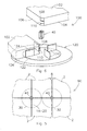
- fig. 1 shows a partly exploded perspective view of a first embodiment of an assembly according to the present invention;
- fig. 2 shows a detail of the embodiment of fig. 1 with a stabilizing element in a first position of use;
- fig. 3 shows a perspective view of a stabilizing element according to the present invention in a second position of use;
- fig. 4 shows a cross-sectional side view of an embodiment of a stabilizing element according to the invention;
- fig. 5 shows a schematic top view of an assembly according to the present invention;
- fig. 6 is a partly exploded perspective view of a second embodiment of an assembly according to the present invention;
- fig. 7 is a partly exploded perspective view of a third embodiment of an assembly according to the present invention; and
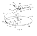
- fig. 8 shows a clarification in detail of the embodiment of fig. 1.
- As shown in fig. 1, an
assembly 1 for forming a floor according to the present invention comprises one ormore tiles 2.Tiles 2 can have any desired shape and dimension. In the embodiment shown in fig. 1 the tiles are elongate or square and provided withside walls Tile 2 is provided at a corner withchamfered part 8. The tiles are arranged in a plane and have a flat top side and/or underside. - An adjusting
element 10 is arranged under the corner of the tile. Adjustingelement 10 comprises a quarter disc-shapedplate 12 which is provided on the straight sides withupright walls upright walls upright walls adjacent tiles 2 is thus determined by the thickness of upright walls 14-20. Adjustingelement 10 is provided at a corner with aupright strip 22. Aconcave recess 24 is arranged in the upright strip. The concave recess is concave in height direction of the upright strip, i.e. transversely of the plane of the tiles. On the rounded side theplate 12 of adjustingelement 10 is provided withprotrusions 26.Protrusions 26 are arranged onplate 12 with some mutual spacing opposite the side where walls 14-20 andstrip 22 extend. The mutual spacing between the protrusions serves, among other purposes, for the drainage of rainwater during storage of the tiles. The protrusions serve here to fix a support element. - Adjusting
elements 10 are for instance arranged on the underside of the corners oftiles 2 by means of glueing. Upright walls 14-20 herein connect toside walls tiles 2. Upright strips 22 connect to chamferedparts 8 oftiles 2. Adjustingelements 10 withtiles 2 thereon are arranged on a disc-shapedsupport element 30.Support element 30 is preferably of an elastic material, such as rubber or an elastic plastic, in order to damp vibrations.Protrusions 26 connect to aside edge 32 of the support element and thus fix the support element. - A
coupling element 40 is arranged connecting to upright strips 22. As shown more clearly in fig. 2 and 3,coupling element 40 comprises an elastic, beam-likemiddle part 42 which is enclosed between twoharder clamping parts 44, 46 (fig. 3). Abolt 48 is arranged throughcoupling element 40 and has ascrew head 50 which can be reached above clampingpart 44. - Coupling
part 40 can be compressed by means ofcotter bolt 48.Middle part 42 can expand correspondingly, wherein side walls ofmiddle part 42 connect toupright strips 22 and therecesses 24 arranged therein. - As shown in fig. 4, an embodiment of a
coupling part 60 comprises anelastic body 62 of a suitable material such as rubber or plastic. Elastomers of polyurethane (PU) will for instance suffice as plastic.Body 62 is for instance tubular, cylindrical or beam-like. An elongate, continuous opening is arranged inbody 62. Expanding elements, such as a (cotter)bolt 66, are arranged in the opening ofbody 62.Cotter bolt 66 comprises abolt 68 at a first outer end and anut 70 at the opposite outer end.Nut 70 is embedded in a clampingpart 74 which is provided with anelongate opening 72 and has a T-shaped cross-section.Outer end 76 of clampingpart 74 is tapering. The taperingend 76 is for instance pyramid-shaped or conical. A clampingpart 80 of T-shaped cross-section is arranged at the end ofcoupling element 60 opposite clampingpart 74. Clampingpart 80 is provided with anouter end 82 which is provided with an opening for receiving the taperingouter end 76. The opening ofouter end 82 for instance takes the form of an inverted pyramid or cone.Flexible body 62 is arranged between the T-parts and round outer ends 76, 82 of clampingpart 74 and clampingpart 80.Tiles 2 with theirrecesses 24 are also shown. - A
floor 90 assembled from the above described components is shown in fig. 5.Tiles 2 are roughly square withchamfered corners 8. The intermediate distance betweenadjacent tiles 2 is determined by the thickness of upright walls 14-20. The corners oftiles 2 rest onsupport elements 30. Couplingelements 40 are arranged between the corners. Couplingelements 40 are compressed bycotter bolt 48 such thatmiddle part 42 has expanded intorecesses 24. - In another embodiment, shown in fig. 6, an
assembly 100 for forming a floor comprises one ormore tiles 102. The tiles are provided withside walls Tiles 102 are provided at a corner with achamfered part 108. Aconcave recess 110 is arranged roughly in the centre ofchamfered part 108. -
Tiles 102 are arranged with their corners onpositioning element 120.Positioning element 120 comprises a disc-shapedplate 122 which is provided on the top side withupright walls 124. Sincetiles 102 are square or elongate in the shown embodiment,plate 122 is provided with fourupright walls 124. If other tile shapes are used with more or fewer side walls, more or fewerupright walls 124 can likewise be provided.Side walls 124position tiles 102 in the correct manner and the thickness ofupright walls 124 provides for a desired mutual spacing between the tiles. -
Plate 122 is arranged in a circular recess in a top side ofsupport element 126. The circular recess is arranged such that the top side ofplate 122 is roughly flush with the top side ofsupport element 126. -
Plate 122,upright walls 124 and/orsupport element 126 are preferably flexible. A suitable material is for instance natural or synthetic rubber.Upright walls 124 have a height which is in the order of the height ofside walls - In a practical embodiment the
support element 126 has a diameter in the order of 400 mm and a thickness of about 30 mm.Plate 122 has a diameter in the order of 200 mm and a thickness of about 2 mm.Walls 124 have for instance a thickness in the order of 2 mm. - At the position where the corners of
tiles 102 come together, acoupling element 40 is arranged therebetween. Couplingelement 40 is otherwise the same as the coupling element shown in fig. 1-3. The coupling element shown in fig. 4 can also be used. A convex outer wall ofcoupling element 40 engages in theconcave recess 110 oftiles 102 for fixing thereof in vertical and horizontal direction. - In top view a floor assembled from
tiles 102 and supportelements 120 appears substantially the same as the assembly shown in fig. 5. - Variations in thickness of
tiles 102 are absorbed by grindingtiles 102 to the desired thickness, at least at their corners. For this purpose thetiles 102 are for instance manufactured from slightly damp concrete. A variation in the thickness of the tiles in the order of +/-0.5 mm can be achieved after grinding. Height adjustment during laying the floor is thus unnecessary, so that the floor can be laid relatively quickly. - Owing to the relatively strong type of concrete, relatively large tiles can be manufactured with dimensions greater than 1 m x 1 m and a weight above 200 kg. The hollow sound is likewise prevented by the great weight.
- In the embodiment shown in fig. 7 the assembly 150 comprises
tiles 152 provided withside walls tiles 152 are provided with achamfered part 158. A quarter-circular recess 162 is arranged on the underside oftiles 152 at the corners of the tiles. - The corners of
tiles 152 are arranged ontensioning element 170. Tensioningelement 170 comprises a disc-shapedpart 172 which is provided on a top side with for instance fourupright walls 174.Upright walls 174 have a thickness which defines the mutual spacing between adjacent tiles. The corners oftiles 152 are arranged between and connect to two of theupright walls 174. Disc-shapedpart 172 has a shape corresponding to recess 162 on the underside of the tiles. Roughly parallel to its central axis the tensioning element is provided with a threadedhole 176. - A
support element 180 is arranged undertensioning element 170.Support element 180 is preferably disc-shaped and flexible, i.e. manufactured from an elastic material so as to damp vibrations. - For renovation and fixing of tiles a
coupling element 182 is arranged betweenchamfered parts 158 of the corners ofadjacent tiles 152. Couplingelement 182 comprises acontinuous bolt 184 which is provided with aprotruding part 186. With the exception of protrudingpart 186,coupling element 182 is the same ascoupling element 40 shown in fig. 1-3.Bolt 184 is fastened in threadedhole 176 oftensioning element 170 usingprotruding part 186. - In the manufacture of
floor 90 as shown in fig. 5 using an assembly as shown in fig. 1,tiles 2 are produced and cured. The production takes place for instance by pressing concrete in a mould. The thickness oftiles 2 is measured at the corners thereof. - Adjusting
elements 10 are available in a number of variants, whereinplate 12 always has a different thickness. The thickness ofplates 12 varies in steps, which are small enough to keep the variation in thickness of the tiles within a predetermined range. That is, variations in thickness can be limited to within a desired range in efficient and cost-effective manner by applyingplates 12 of a varying thickness. The chosen adjustingelements 10 are then arranged on the underside of the corners oftiles 2. - During laying of
floor 90support elements 32 are for instance arranged on a substrate at predetermined intermediate distances.Tiles 2 provided with adjustingelements 10 are arranged on the respective support elements, whereinprotrusions 26 connect to the edges of the support elements. - Coupling
elements 40 are then arranged between the corners ofadjacent tiles 2.Screw head 50 ofcotter bolt 48 is then tightened for the purpose of compressing and expandingmiddle part 42. The outer walls of the middle part here take on a convex form.Screw head 50 is now tightened until the outer wall ofmiddle part 42 fits ontoconcave recess 24. A fixation oftiles 2 thus results in both horizontal and vertical direction. This fixation prevents rattling oftiles 2. - The application of a
coupling element 60 as shown in fig. 4 takes place in similar manner. - When laying a floor using the embodiment as shown in figure 6,
tiles 102 are produced and cured. - The thickness of (the corners of)
tiles 102 is then measured. The thickness oftiles 102 is modified, for instance by grinding, such that the variation in thickness of the tiles falls within a predetermined range. This range is for instance in the order of +/- 0.5 mm.Concave recesses 110 are also arranged. - Grinding the corner of the tiles to thickness takes place for instance by creating a quarter-circular recess with a radius in the order of that of
support element 126. The corner ground to thickness thus provides for fixation of the support element. - During laying of the floor the
support elements 126 withpositioning elements 120 thereon are arranged at predetermined intermediate distances on a substrate.Tiles 102 are arranged on the respective support elements, whereinside walls tiles 102 connect toupright walls 124 of the positioning elements. - Coupling
elements adjacent tiles 102.Screw head 50 ofcotter bolt 48 is then tightened so as to compress and expandmiddle part 42. The outer walls of the middle part herein take on a convex form.Screw head 50 is now tightened until the outer wall ofmiddle part 42 fits ontoconcave recess 110. A fixation oftiles 102 is thus created in both horizontal and vertical direction. -
Tiles 152 of the embodiment shown in fig. 7 are moulded in a formwork and removed therefrom after curing. To enable removal of curedtiles 152 from the formwork, the round walls ofrecesses 162 are tapering. That is, the radius ofrecess 162 becomes greater in the direction of the underside oftiles 152 to be placed onsupport elements 180. - During laying of the floor the
support elements 180 with tensioningelements 170 thereon are arranged on a substrate at predetermined intermediate distances.Tiles 152 are arranged on the respective tensioning elements, whereinside walls tiles 152 connect toupright walls 174 of the tensioning elements. - For renovation of the thus formed floor and for fixation of tiles in vertical direction, the
coupling elements 182 are arranged betweenchamfered parts 158 of the corners ofadjacent tiles 152.Cotter bolt 184 is now tightened until the convex outer wall ofmiddle part 42 of the coupling element fits firmly ontochamfered part 158. - In a practical embodiment the dimensions of
coupling element 182 can be varied more than the diameter oftensioning element 170. Where tensioningelement 170 has a diameter which can be increased by about 4 mm,coupling element 182 has a cross-sectional dimension which can be varied by 8 to 10 mm by tightening the cotter bolt. Shifting of the coupling element in vertical direction is prevented here in that theprotruding part 186 is arranged in threadedhole 176. - A floor formed in one of the above described ways is shown in top view in fig. 5. At the outermost edges such a floor connects with for instance an intermediate space to walls or an outer wall of a building (not shown). The floors formed according to the present invention are provided for this purpose with a so-called edge enclosure. The edge enclosure is a mixture which is arranged in the intermediate space between the outermost edges of the floor and the walls of the building. The mixture comprises for instance rubber granulate, alumina silicate and/or a binder. The alumina silicate is black and comprises for
instance 1/3 part grains. The binder is for instance polyurethane glue (PU). The mixture is prepared in situ when laying the floor, and arranged in the intermediate space which is in the order of 4 to 6 cm wide. - In a practical embodiment the tiles of the different embodiments have for instance a length and width of 90 cm x 90 cm, with a weight in the order of 150 kg. In another embodiment the tiles have a length and a width in the order of 110 cm x 110 cm, with a weight in the order of 250 kg.
- Concrete is recommended as material for the tiles. In one embodiment slightly damp concrete is applied. The fluctuation in the thickness of the tiles is for instance in the order of +/- 2 mm. When slightly damp concrete is used, the fluctuation in thickness after grinding is for instance in the order of +/- 0.5 mm.
- Upright walls 14-20 of the adjusting elements have for instance a thickness in the order of 2 mm. The adjusting elements are for instance manufactured from polystyrene (PS). In order to compensate variations in thickness in the tiles,
plates 12 of the adjusting elements are applied in different thicknesses. Five, six or ten different plates can for instance thus be available, with thicknesses varying in steps in the order of 1 mm. The average thickness ofplates 12 lies for instance in a range of 1 to 10 mm, depending on mutual variation of the tiles. The effective variation in thickness between adjacent corners of tiles can thus be limited to for instance a maximum of +/- 0.5 mm in relatively simple and inexpensive manner. - The overall thickness, which consists of the thickness of a corner of a tile plus the thickness of the plate of an adjusting element arranged under the corner, can thus be corrected to a determined accuracy. The accuracy is determined by adapting the thickness of the plate of the adjusting element so as to approach as well as possible a desired overall thickness.
- Adjusting elements 10 (fig. 1) are for instance connected to the tiles by means of glueing. In an embodiment use is made for glueing purposes of a glue comprising polyurethane (PU). This glue can withstand shear forces up to for instance 1200 kg. If vehicles such as cars with a weight in the order of 3500 kg drive over a floor, shear forces of up to about 500 kg are caused. The assembly according to the present invention is therefore highly suitable for forming a floor over which cars drive, such as on the various floors of multi-storey car parks or on roof car parks.
- The side walls of the different tiles are for instance provided with recesses (not shown) for passage of rainwater.
- In a practical embodiment the
recesses - Fig. 1 and 6 show an example of a single-
curve recess - An example of a two-curve recess is shown in fig. 8. The assembly shown in fig. 8 is a detail of the embodiment of fig. 1 and corresponds therewith, with the exception of the recess.
Recess 24 curves in two directions. That is, the form of the recess forms a part of the surface of animaginary egg 25. The thickness d1 in the centre of the recess is smaller than thickness d2 on the side surface of the strip. Thickness d2 is for instance in the order of 2 to 5 mm, for instance 3 mm. Owing to the two-curve form,recess 24 connects better to the outer surface ofcoupling element 40. In addition, the upright strip has a higher bending stiffness at the position of the recess than in the case of a single-curve recess. - Other forms of the recess with a gradually sloping wall can be envisaged.
- The height of
recess element Recesses - The depth of the recess is always small in relation to the height. The force of coupling element exerted in vertical direction on the recess thus increases gradually with an increasing vertical displacement, such as when load increases. The depth of
recess Recesses - When the bolt is tightened in
tensioning element recess - The outer side of the tensioning element protrudes for instance about 2% to 20% of the height of the tensioning element, or for instance about 1, 2, 3, 4 or 5 mm.
- When they are tightened,
coupling elements recesses - Under heavy load the tiles can compress the flexible body of the coupling element. When the load ceases, the flexible body of the coupling element will push the tiles back again into their original position due to the resilience of the material from which it is made.
- Rattling of the tiles relative to each other is thus prevented.
- The expansion of the coupling elements and their possible co-action with
recesses recess - Fluctuations in thickness of the tiles can here be compensated by the assembly according to the invention. A cost-saving is achieved by compensating the fluctuation in thickness by using adjusting elements of differing thickness. This is because the adjusting elements are made of a cheaper material, and one or more steps of processing the material of the tiles - which is relatively hard and difficult to process - are omitted.
- The advantages of the recess and the adjusting elements can be combined, as shown in Fig. 1. Adjusting
element 10 makes it possible to compensate fluctuations in thickness, wherein adapting the thickness of the concrete oftiles 2 is unnecessary.Recess 24 is herein arranged inupright strip 22, which connects to the chamferedside 8 oftile 2. Processing of the chamfered side for the purpose of arranging a recess (such asrecess 110 in Fig. 6) is thus also unnecessary. Since the concrete is a relatively hard material, the omission of steps for processing the concrete results in a cost advantage and a time saving. - In addition, a chamber arranged in a side wall of a tile, as described in
EP-0203226-A1 , is precluded from the definition ofconcave recess EP-0203226-A1 comprises three wall parts, i.e. a cylindrical middle wall part which connects at the top and bottom to a conical upper and lower wall part. The upper wall part and the lower wall part connect to the middle wall part at an acute angle, as shown in cross-section in figure 6 ofEP-0203226-A1 . Since a system according toEP-0203226-A1 as used in practice applies cylindrical coupling elements with a diameter of about 10 cm, the cylindrical wall part of the chambers would have a radius of about 5 cm. - The above described embodiments serve only as example. Many modifications thereof are possible within the scope of the appended claims. Features and elements of individually described embodiments can for instance be applied in combination.
wherein the engaging surface comprises a recess with a gradually sloping wall for producing, in co-action with the coupling element, a force transversely of the plane of the tiles which gradually increases as load increases.
wherein the second clamping part has a T-shaped cross-section and wherein an outer end of the second clamping part is provided with an opening for receiving the tapering end of the first clamping part; and
wherein the flexible middle part is arranged between the T-parts and round the tapering end of the first clamping part and the outer end of the second clamping part.
Claims (16)
- Assembly for forming a floor on a substrate, comprising:- a number of tiles arranged substantially in a plane and having a top side, a bottom side and side surfaces;- a coupling element arranged between adjacent tiles and having a dimension which is variable in the direction of the plane,wherein the coupling element is adapted to engage on an engaging surface coupled to the side surface of a tile, and
wherein the engaging surface comprises a recess with a gradually sloping wall for producing, in co-action with the coupling element, a force transversely of the plane of the tiles which gradually increases as load increases. - Assembly as claimed in claim 1, wherein the wall of the recess is curved substantially in a single direction or in two directions.
- Assembly as claimed in claim 1 or 2, wherein a wall of the recess has a continuous progression.
- Assembly as claimed in any of the claims 1-3, wherein the recess has a depth in the range of about 5% to 25% of the height of the recess.
- Assembly as claimed in any of the claims 1-4, wherein the recess is about 1 to 5 mm deep.
- Assembly as claimed in any of the claims 1-5, wherein the height of the recess is about 20% to 50% of the height of the tiles or of the height of the coupling element.
- Assembly as claimed in any of the claims 1-6, wherein corners of the tiles are provided with a chamfered part, and
wherein the recess is arranged in the chamfered part of the tile. - Assembly as claimed in any of the claims 1-6,
wherein each corner of the tiles is provided with a separate adjusting element,
wherein each adjusting element is provided with an upright strip connecting to the respective corner of the tile for the purpose of forming the engaging surface,
wherein the recess is arranged in the upright strip. - Assembly as claimed in claim 8,
wherein the adjusting element comprises a plate which has a thickness,
wherein the overall thickness, which consists of the thickness of a corner of a tile plus the thickness of the plate of an adjusting element arranged under the corner, can be corrected with a determined accuracy to a predetermined thickness by adapting the thickness of the plate of the adjusting element. - Assembly as claimed in claim 9, wherein the thicknesses of the plates of different adjusting elements vary in steps in the order of 1 mm.
- Assembly as claimed in claim 9 or 10, wherein the plate of the adjusting element is provided on the side opposite the upright strip with protrusions which connect to a support element arranged under the plate.
- Assembly as claimed in any of the foregoing claims,
wherein the coupling element comprises:- a first clamping part;- a second clamping part;- a flexible middle part arranged between the first clamping part and the second clamping part;- a bolt arranged through the clamping parts and the middle part for varying the diameter of the middle part,wherein the first clamping part has a T-shaped cross-section and a tapering end;
wherein the second clamping part has a T-shaped cross-section and wherein an outer end of the second clamping part is provided with an opening for receiving the tapering end of the first clamping part; and
wherein the flexible middle part is arranged between the T-parts and round the tapering end of the first clamping part and the outer end of the second clamping part. - Assembly as claimed in claim 12,
wherein the coupling element is arranged on a tensioning element,
wherein the bolt is longer than the coupling element, and
wherein the part of the bolt protruding from the coupling element is arranged in the tensioning element. - Adjusting element for an assembly as claimed in any of the claims 1-13, comprising:- a plate to be arranged under a corner of a tile;- an upright strip connected to the plate and connectable to the corner of the tile;wherein in the upright strip is arranged a recess which is concave in a direction transversely of the plane of the tile and which has for instance substantially the shape of an ellipse or of an ellipsoid.
- Coupling element for an assembly as claimed in any of the claims 1-13, comprising:- a first clamping part which has a T-shaped cross-section and a tapering end;- a second clamping part which has a T-shaped cross-section and wherein an outer end of the second clamping part is provided with an opening for receiving the tapering end of the first clamping part;- a flexible middle part arranged between the first clamping part and the second clamping part;- a bolt arranged through the clamping parts and the middle part for varying the diameter of the middle part,wherein the flexible middle part is arranged between the T-parts and round the tapering end of the first clamping part and the outer end of the second clamping part.
- Method for forming a floor on a substrate, comprising of:- arranging substantially in a plane a number of tiles with a top side, a bottom side and side surfaces;- arranging a coupling element with a variable diameter between adjacent tiles,wherein the coupling element is adapted to engage in a recess arranged on one or more of the side surfaces of the tiles, which recess comprises a gradually sloping wall for producing, in co-action with the coupling element, a force transversely of the plane of the tiles which gradually increases as load increases.
Applications Claiming Priority (1)
| Application Number | Priority Date | Filing Date | Title |
|---|---|---|---|
| NL1032369A NL1032369C2 (en) | 2006-08-25 | 2006-08-25 | Assembly and method for forming a floor. |
Publications (3)
| Publication Number | Publication Date |
|---|---|
| EP1897994A2 true EP1897994A2 (en) | 2008-03-12 |
| EP1897994A3 EP1897994A3 (en) | 2013-02-27 |
| EP1897994B1 EP1897994B1 (en) | 2017-11-01 |
Family
ID=38042585
Family Applications (1)
| Application Number | Title | Priority Date | Filing Date |
|---|---|---|---|
| EP07075731.5A Active EP1897994B1 (en) | 2006-08-25 | 2007-08-27 | Assembly and method for forming a floor |
Country Status (2)
| Country | Link |
|---|---|
| EP (1) | EP1897994B1 (en) |
| NL (1) | NL1032369C2 (en) |
Cited By (5)
| Publication number | Priority date | Publication date | Assignee | Title |
|---|---|---|---|---|
| WO2018044158A1 (en) | 2016-08-31 | 2018-03-08 | Zoontjens Beton B.V. | System and method for forming a tiled floor |
| FR3090016A1 (en) | 2018-12-17 | 2020-06-19 | Dalles de France | Prefabricated concrete slab device suitable for vehicles up to 3.5 tonnes whose weight is less than 50 kg per slab |
| EP3851580A1 (en) | 2020-01-20 | 2021-07-21 | Zoontjens International B.V. | Rooftop paving assembly for cars |
| WO2021259946A1 (en) * | 2020-06-25 | 2021-12-30 | QiR² international GmbH | Connecting element for floor covering bodies, and cross spacer |
| WO2024197346A1 (en) * | 2023-03-28 | 2024-10-03 | Elmich Pte Ltd | Concealed paver retainer |
Family Cites Families (4)
| Publication number | Priority date | Publication date | Assignee | Title |
|---|---|---|---|---|
| EP0203226B1 (en) * | 1985-05-29 | 1990-03-21 | Anjap N.V. | Tile element fixing means and tile element covering provided with such tile element fixing means |
| DE29918998U1 (en) * | 1999-10-28 | 2000-03-30 | Steffens, Sandra, 21465 Reinbek | Device for aligning and / or bracing building boards |
| WO2001090497A1 (en) * | 2000-05-25 | 2001-11-29 | John Repasky | Ballast block deck system and pedestal assembly therefor |
| DE10155980A1 (en) * | 2001-11-14 | 2003-05-22 | Dietrich Poburski | baseplate |
-
2006
- 2006-08-25 NL NL1032369A patent/NL1032369C2/en active Search and Examination
-
2007
- 2007-08-27 EP EP07075731.5A patent/EP1897994B1/en active Active
Non-Patent Citations (1)
| Title |
|---|
| None |
Cited By (7)
| Publication number | Priority date | Publication date | Assignee | Title |
|---|---|---|---|---|
| WO2018044158A1 (en) | 2016-08-31 | 2018-03-08 | Zoontjens Beton B.V. | System and method for forming a tiled floor |
| NL2017397B1 (en) * | 2016-08-31 | 2018-03-08 | Zoontjens Beton B V | System for forming a tiled floor on an outdoor subsurface, combination of a tile and a corner element, tiled floor, method for assembling a tiled floor |
| FR3090016A1 (en) | 2018-12-17 | 2020-06-19 | Dalles de France | Prefabricated concrete slab device suitable for vehicles up to 3.5 tonnes whose weight is less than 50 kg per slab |
| EP3851580A1 (en) | 2020-01-20 | 2021-07-21 | Zoontjens International B.V. | Rooftop paving assembly for cars |
| NL2024710B1 (en) | 2020-01-20 | 2021-09-08 | Zoontjens Int B V | Rooftop Paving Assembly For Cars |
| WO2021259946A1 (en) * | 2020-06-25 | 2021-12-30 | QiR² international GmbH | Connecting element for floor covering bodies, and cross spacer |
| WO2024197346A1 (en) * | 2023-03-28 | 2024-10-03 | Elmich Pte Ltd | Concealed paver retainer |
Also Published As
| Publication number | Publication date |
|---|---|
| EP1897994B1 (en) | 2017-11-01 |
| NL1032369C2 (en) | 2008-02-26 |
| EP1897994A3 (en) | 2013-02-27 |
Similar Documents
| Publication | Publication Date | Title |
|---|---|---|
| EP1897994B1 (en) | Assembly and method for forming a floor | |
| CN100424268C (en) | Track noise control device and sound absorption flat plate used in same | |
| US6230460B1 (en) | Resilient flooring system | |
| JP3046566U (en) | Hollow floor | |
| US20060201092A1 (en) | Carrier tile consisting of film-like plastic | |
| CA2668169C (en) | Sub-floor assemblies for sports flooring systems | |
| HU227768B1 (en) | Fixing device for a laminated wall element | |
| KR101517119B1 (en) | Lower support of sectional dome structure | |
| KR101972320B1 (en) | A assembly type versatile sidewalk block | |
| CN102216544A (en) | Sub-floor assemblies for sports flooring systems | |
| JP7319152B2 (en) | cushioning material | |
| AU2009101012B4 (en) | Expansion joints and formwork for concrete | |
| CN211850588U (en) | Assembled ground plate structure | |
| KR101105627B1 (en) | Floor shock sound blocking structure of building | |
| CN208899319U (en) | A kind of comb-tooth bridge expansion device | |
| NL2024710B1 (en) | Rooftop Paving Assembly For Cars | |
| KR102638574B1 (en) | Floor structure for preventing noise between floors | |
| KR101983692B1 (en) | Shock and noise diminution device, manufacturing method thereof, and floating floor system in apartment house using the same | |
| JP5863132B1 (en) | Method for forming joints between concrete precast blocks | |
| KR100609309B1 (en) | Artificial stone board for building and exterior | |
| KR200347584Y1 (en) | Articial stone plate for interior outside a structure | |
| SU1629435A1 (en) | Retained formwork | |
| JPH11100976A (en) | Heat insulation double-floor unit and floor panel with heat insulation material and execution for the floor | |
| EP1621673B1 (en) | Floor construction | |
| JP3673439B2 (en) | Elastic joint material |
Legal Events
| Date | Code | Title | Description |
|---|---|---|---|
| PUAI | Public reference made under article 153(3) epc to a published international application that has entered the european phase |
Free format text: ORIGINAL CODE: 0009012 |
|
| AK | Designated contracting states |
Kind code of ref document: A2 Designated state(s): AT BE BG CH CY CZ DE DK EE ES FI FR GB GR HU IE IS IT LI LT LU LV MC MT NL PL PT RO SE SI SK TR |
|
| AX | Request for extension of the european patent |
Extension state: AL BA HR MK YU |
|
| PUAL | Search report despatched |
Free format text: ORIGINAL CODE: 0009013 |
|
| AK | Designated contracting states |
Kind code of ref document: A3 Designated state(s): AT BE BG CH CY CZ DE DK EE ES FI FR GB GR HU IE IS IT LI LT LU LV MC MT NL PL PT RO SE SI SK TR |
|
| AX | Request for extension of the european patent |
Extension state: AL BA HR MK RS |
|
| RIC1 | Information provided on ipc code assigned before grant |
Ipc: E01C 5/00 20060101AFI20130118BHEP |
|
| 17P | Request for examination filed |
Effective date: 20130826 |
|
| RBV | Designated contracting states (corrected) |
Designated state(s): AT BE BG CH CY CZ DE DK EE ES FI FR GB GR HU IE IS IT LI LT LU LV MC MT NL PL PT RO SE SI SK TR |
|
| AKX | Designation fees paid |
Designated state(s): AT BE BG CH CY CZ DE DK EE ES FI FR GB GR HU IE IS IT LI LT LU LV MC MT NL PL PT RO SE SI SK TR |
|
| 17Q | First examination report despatched |
Effective date: 20150904 |
|
| STAA | Information on the status of an ep patent application or granted ep patent |
Free format text: STATUS: EXAMINATION IS IN PROGRESS |
|
| GRAP | Despatch of communication of intention to grant a patent |
Free format text: ORIGINAL CODE: EPIDOSNIGR1 |
|
| STAA | Information on the status of an ep patent application or granted ep patent |
Free format text: STATUS: GRANT OF PATENT IS INTENDED |
|
| INTG | Intention to grant announced |
Effective date: 20170606 |
|
| GRAS | Grant fee paid |
Free format text: ORIGINAL CODE: EPIDOSNIGR3 |
|
| GRAA | (expected) grant |
Free format text: ORIGINAL CODE: 0009210 |
|
| STAA | Information on the status of an ep patent application or granted ep patent |
Free format text: STATUS: THE PATENT HAS BEEN GRANTED |
|
| AK | Designated contracting states |
Kind code of ref document: B1 Designated state(s): AT BE BG CH CY CZ DE DK EE ES FI FR GB GR HU IE IS IT LI LT LU LV MC MT NL PL PT RO SE SI SK TR |
|
| REG | Reference to a national code |
Ref country code: GB Ref legal event code: FG4D |
|
| REG | Reference to a national code |
Ref country code: AT Ref legal event code: REF Ref document number: 942153 Country of ref document: AT Kind code of ref document: T Effective date: 20171115 Ref country code: CH Ref legal event code: EP |
|
| REG | Reference to a national code |
Ref country code: IE Ref legal event code: FG4D |
|
| REG | Reference to a national code |
Ref country code: DE Ref legal event code: R096 Ref document number: 602007052858 Country of ref document: DE |
|
| REG | Reference to a national code |
Ref country code: NL Ref legal event code: FP |
|
| REG | Reference to a national code |
Ref country code: LT Ref legal event code: MG4D |
|
| REG | Reference to a national code |
Ref country code: AT Ref legal event code: MK05 Ref document number: 942153 Country of ref document: AT Kind code of ref document: T Effective date: 20171101 |
|
| PG25 | Lapsed in a contracting state [announced via postgrant information from national office to epo] |
Ref country code: SE Free format text: LAPSE BECAUSE OF FAILURE TO SUBMIT A TRANSLATION OF THE DESCRIPTION OR TO PAY THE FEE WITHIN THE PRESCRIBED TIME-LIMIT Effective date: 20171101 Ref country code: FI Free format text: LAPSE BECAUSE OF FAILURE TO SUBMIT A TRANSLATION OF THE DESCRIPTION OR TO PAY THE FEE WITHIN THE PRESCRIBED TIME-LIMIT Effective date: 20171101 Ref country code: LT Free format text: LAPSE BECAUSE OF FAILURE TO SUBMIT A TRANSLATION OF THE DESCRIPTION OR TO PAY THE FEE WITHIN THE PRESCRIBED TIME-LIMIT Effective date: 20171101 Ref country code: ES Free format text: LAPSE BECAUSE OF FAILURE TO SUBMIT A TRANSLATION OF THE DESCRIPTION OR TO PAY THE FEE WITHIN THE PRESCRIBED TIME-LIMIT Effective date: 20171101 |
|
| PG25 | Lapsed in a contracting state [announced via postgrant information from national office to epo] |
Ref country code: BG Free format text: LAPSE BECAUSE OF FAILURE TO SUBMIT A TRANSLATION OF THE DESCRIPTION OR TO PAY THE FEE WITHIN THE PRESCRIBED TIME-LIMIT Effective date: 20180201 Ref country code: AT Free format text: LAPSE BECAUSE OF FAILURE TO SUBMIT A TRANSLATION OF THE DESCRIPTION OR TO PAY THE FEE WITHIN THE PRESCRIBED TIME-LIMIT Effective date: 20171101 Ref country code: GR Free format text: LAPSE BECAUSE OF FAILURE TO SUBMIT A TRANSLATION OF THE DESCRIPTION OR TO PAY THE FEE WITHIN THE PRESCRIBED TIME-LIMIT Effective date: 20180202 Ref country code: IS Free format text: LAPSE BECAUSE OF FAILURE TO SUBMIT A TRANSLATION OF THE DESCRIPTION OR TO PAY THE FEE WITHIN THE PRESCRIBED TIME-LIMIT Effective date: 20180301 Ref country code: LV Free format text: LAPSE BECAUSE OF FAILURE TO SUBMIT A TRANSLATION OF THE DESCRIPTION OR TO PAY THE FEE WITHIN THE PRESCRIBED TIME-LIMIT Effective date: 20171101 |
|
| PG25 | Lapsed in a contracting state [announced via postgrant information from national office to epo] |
Ref country code: SK Free format text: LAPSE BECAUSE OF FAILURE TO SUBMIT A TRANSLATION OF THE DESCRIPTION OR TO PAY THE FEE WITHIN THE PRESCRIBED TIME-LIMIT Effective date: 20171101 Ref country code: CZ Free format text: LAPSE BECAUSE OF FAILURE TO SUBMIT A TRANSLATION OF THE DESCRIPTION OR TO PAY THE FEE WITHIN THE PRESCRIBED TIME-LIMIT Effective date: 20171101 Ref country code: CY Free format text: LAPSE BECAUSE OF FAILURE TO SUBMIT A TRANSLATION OF THE DESCRIPTION OR TO PAY THE FEE WITHIN THE PRESCRIBED TIME-LIMIT Effective date: 20171101 Ref country code: EE Free format text: LAPSE BECAUSE OF FAILURE TO SUBMIT A TRANSLATION OF THE DESCRIPTION OR TO PAY THE FEE WITHIN THE PRESCRIBED TIME-LIMIT Effective date: 20171101 Ref country code: DK Free format text: LAPSE BECAUSE OF FAILURE TO SUBMIT A TRANSLATION OF THE DESCRIPTION OR TO PAY THE FEE WITHIN THE PRESCRIBED TIME-LIMIT Effective date: 20171101 |
|
| REG | Reference to a national code |
Ref country code: DE Ref legal event code: R097 Ref document number: 602007052858 Country of ref document: DE |
|
| REG | Reference to a national code |
Ref country code: FR Ref legal event code: PLFP Year of fee payment: 12 |
|
| PG25 | Lapsed in a contracting state [announced via postgrant information from national office to epo] |
Ref country code: PL Free format text: LAPSE BECAUSE OF FAILURE TO SUBMIT A TRANSLATION OF THE DESCRIPTION OR TO PAY THE FEE WITHIN THE PRESCRIBED TIME-LIMIT Effective date: 20171101 Ref country code: RO Free format text: LAPSE BECAUSE OF FAILURE TO SUBMIT A TRANSLATION OF THE DESCRIPTION OR TO PAY THE FEE WITHIN THE PRESCRIBED TIME-LIMIT Effective date: 20171101 |
|
| PLBE | No opposition filed within time limit |
Free format text: ORIGINAL CODE: 0009261 |
|
| STAA | Information on the status of an ep patent application or granted ep patent |
Free format text: STATUS: NO OPPOSITION FILED WITHIN TIME LIMIT |
|
| 26N | No opposition filed |
Effective date: 20180802 |
|
| PG25 | Lapsed in a contracting state [announced via postgrant information from national office to epo] |
Ref country code: SI Free format text: LAPSE BECAUSE OF FAILURE TO SUBMIT A TRANSLATION OF THE DESCRIPTION OR TO PAY THE FEE WITHIN THE PRESCRIBED TIME-LIMIT Effective date: 20171101 |
|
| PG25 | Lapsed in a contracting state [announced via postgrant information from national office to epo] |
Ref country code: MC Free format text: LAPSE BECAUSE OF FAILURE TO SUBMIT A TRANSLATION OF THE DESCRIPTION OR TO PAY THE FEE WITHIN THE PRESCRIBED TIME-LIMIT Effective date: 20171101 |
|
| REG | Reference to a national code |
Ref country code: CH Ref legal event code: PL |
|
| PG25 | Lapsed in a contracting state [announced via postgrant information from national office to epo] |
Ref country code: LI Free format text: LAPSE BECAUSE OF NON-PAYMENT OF DUE FEES Effective date: 20180831 Ref country code: CH Free format text: LAPSE BECAUSE OF NON-PAYMENT OF DUE FEES Effective date: 20180831 |
|
| PG25 | Lapsed in a contracting state [announced via postgrant information from national office to epo] |
Ref country code: MT Free format text: LAPSE BECAUSE OF NON-PAYMENT OF DUE FEES Effective date: 20180827 |
|
| PG25 | Lapsed in a contracting state [announced via postgrant information from national office to epo] |
Ref country code: TR Free format text: LAPSE BECAUSE OF FAILURE TO SUBMIT A TRANSLATION OF THE DESCRIPTION OR TO PAY THE FEE WITHIN THE PRESCRIBED TIME-LIMIT Effective date: 20171101 |
|
| PG25 | Lapsed in a contracting state [announced via postgrant information from national office to epo] |
Ref country code: HU Free format text: LAPSE BECAUSE OF FAILURE TO SUBMIT A TRANSLATION OF THE DESCRIPTION OR TO PAY THE FEE WITHIN THE PRESCRIBED TIME-LIMIT; INVALID AB INITIO Effective date: 20070827 Ref country code: PT Free format text: LAPSE BECAUSE OF FAILURE TO SUBMIT A TRANSLATION OF THE DESCRIPTION OR TO PAY THE FEE WITHIN THE PRESCRIBED TIME-LIMIT Effective date: 20171101 |
|
| PG25 | Lapsed in a contracting state [announced via postgrant information from national office to epo] |
Ref country code: IE Free format text: LAPSE BECAUSE OF NON-PAYMENT OF DUE FEES Effective date: 20180827 |
|
| REG | Reference to a national code |
Ref country code: NL Ref legal event code: HC Owner name: ZOONTJENS INTERNATIONAL B.V.; NL Free format text: DETAILS ASSIGNMENT: CHANGE OF OWNER(S), CHANGE OF OWNER(S) NAME; FORMER OWNER NAME: ZOONTJENS BETON B.V. Effective date: 20200706 |
|
| REG | Reference to a national code |
Ref country code: LU Ref legal event code: HC Owner name: ZOONTJENS INTERNATIONAL B.V.; NL Free format text: FORMER OWNER: ZOONTJENS BETON B.V. Effective date: 20200728 |
|
| REG | Reference to a national code |
Ref country code: BE Ref legal event code: HC Owner name: ZOONTJENS INTERNATIONAL B.V.; NL Free format text: DETAILS ASSIGNMENT: CHANGE OF OWNER(S), CHANGEMENT DE NOM DU PROPRIETAIRE Effective date: 20200722 |
|
| P01 | Opt-out of the competence of the unified patent court (upc) registered |
Effective date: 20230425 |
|
| PGFP | Annual fee paid to national office [announced via postgrant information from national office to epo] |
Ref country code: LU Payment date: 20250804 Year of fee payment: 19 Ref country code: NL Payment date: 20250807 Year of fee payment: 19 |
|
| PGFP | Annual fee paid to national office [announced via postgrant information from national office to epo] |
Ref country code: DE Payment date: 20250804 Year of fee payment: 19 |
|
| PGFP | Annual fee paid to national office [announced via postgrant information from national office to epo] |
Ref country code: IT Payment date: 20250804 Year of fee payment: 19 |
|
| PGFP | Annual fee paid to national office [announced via postgrant information from national office to epo] |
Ref country code: BE Payment date: 20250804 Year of fee payment: 19 Ref country code: GB Payment date: 20250804 Year of fee payment: 19 |
|
| PGFP | Annual fee paid to national office [announced via postgrant information from national office to epo] |
Ref country code: FR Payment date: 20250804 Year of fee payment: 19 |