EP1897794A1 - Straddle-type vehicle - Google Patents
Straddle-type vehicle Download PDFInfo
- Publication number
- EP1897794A1 EP1897794A1 EP07017689A EP07017689A EP1897794A1 EP 1897794 A1 EP1897794 A1 EP 1897794A1 EP 07017689 A EP07017689 A EP 07017689A EP 07017689 A EP07017689 A EP 07017689A EP 1897794 A1 EP1897794 A1 EP 1897794A1
- Authority
- EP
- European Patent Office
- Prior art keywords
- catalyst
- exhaust pipe
- straddle
- engine
- type vehicle
- Prior art date
- Legal status (The legal status is an assumption and is not a legal conclusion. Google has not performed a legal analysis and makes no representation as to the accuracy of the status listed.)
- Granted
Links
Images


Classifications
-
- B—PERFORMING OPERATIONS; TRANSPORTING
- B62—LAND VEHICLES FOR TRAVELLING OTHERWISE THAN ON RAILS
- B62K—CYCLES; CYCLE FRAMES; CYCLE STEERING DEVICES; RIDER-OPERATED TERMINAL CONTROLS SPECIALLY ADAPTED FOR CYCLES; CYCLE AXLE SUSPENSIONS; CYCLE SIDECARS, FORECARS, OR THE LIKE
- B62K11/00—Motorcycles, engine-assisted cycles or motor scooters with one or two wheels
- B62K11/02—Frames
- B62K11/04—Frames characterised by the engine being between front and rear wheels
-
- F—MECHANICAL ENGINEERING; LIGHTING; HEATING; WEAPONS; BLASTING
- F01—MACHINES OR ENGINES IN GENERAL; ENGINE PLANTS IN GENERAL; STEAM ENGINES
- F01N—GAS-FLOW SILENCERS OR EXHAUST APPARATUS FOR MACHINES OR ENGINES IN GENERAL; GAS-FLOW SILENCERS OR EXHAUST APPARATUS FOR INTERNAL-COMBUSTION ENGINES
- F01N13/00—Exhaust or silencing apparatus characterised by constructional features
- F01N13/009—Exhaust or silencing apparatus characterised by constructional features having two or more separate purifying devices arranged in series
-
- F—MECHANICAL ENGINEERING; LIGHTING; HEATING; WEAPONS; BLASTING
- F01—MACHINES OR ENGINES IN GENERAL; ENGINE PLANTS IN GENERAL; STEAM ENGINES
- F01N—GAS-FLOW SILENCERS OR EXHAUST APPARATUS FOR MACHINES OR ENGINES IN GENERAL; GAS-FLOW SILENCERS OR EXHAUST APPARATUS FOR INTERNAL-COMBUSTION ENGINES
- F01N13/00—Exhaust or silencing apparatus characterised by constructional features
- F01N13/08—Other arrangements or adaptations of exhaust conduits
-
- F—MECHANICAL ENGINEERING; LIGHTING; HEATING; WEAPONS; BLASTING
- F01—MACHINES OR ENGINES IN GENERAL; ENGINE PLANTS IN GENERAL; STEAM ENGINES
- F01N—GAS-FLOW SILENCERS OR EXHAUST APPARATUS FOR MACHINES OR ENGINES IN GENERAL; GAS-FLOW SILENCERS OR EXHAUST APPARATUS FOR INTERNAL-COMBUSTION ENGINES
- F01N13/00—Exhaust or silencing apparatus characterised by constructional features
- F01N13/14—Exhaust or silencing apparatus characterised by constructional features having thermal insulation
-
- F—MECHANICAL ENGINEERING; LIGHTING; HEATING; WEAPONS; BLASTING
- F01—MACHINES OR ENGINES IN GENERAL; ENGINE PLANTS IN GENERAL; STEAM ENGINES
- F01N—GAS-FLOW SILENCERS OR EXHAUST APPARATUS FOR MACHINES OR ENGINES IN GENERAL; GAS-FLOW SILENCERS OR EXHAUST APPARATUS FOR INTERNAL-COMBUSTION ENGINES
- F01N2260/00—Exhaust treating devices having provisions not otherwise provided for
- F01N2260/20—Exhaust treating devices having provisions not otherwise provided for for heat or sound protection, e.g. using a shield or specially shaped outer surface of exhaust device
-
- F—MECHANICAL ENGINEERING; LIGHTING; HEATING; WEAPONS; BLASTING
- F01—MACHINES OR ENGINES IN GENERAL; ENGINE PLANTS IN GENERAL; STEAM ENGINES
- F01N—GAS-FLOW SILENCERS OR EXHAUST APPARATUS FOR MACHINES OR ENGINES IN GENERAL; GAS-FLOW SILENCERS OR EXHAUST APPARATUS FOR INTERNAL-COMBUSTION ENGINES
- F01N2340/00—Dimensional characteristics of the exhaust system, e.g. length, diameter or volume of the exhaust apparatus; Spatial arrangements of exhaust apparatuses
- F01N2340/04—Arrangement of the exhaust system relative to a vehicle or parts thereof
-
- F—MECHANICAL ENGINEERING; LIGHTING; HEATING; WEAPONS; BLASTING
- F01—MACHINES OR ENGINES IN GENERAL; ENGINE PLANTS IN GENERAL; STEAM ENGINES
- F01N—GAS-FLOW SILENCERS OR EXHAUST APPARATUS FOR MACHINES OR ENGINES IN GENERAL; GAS-FLOW SILENCERS OR EXHAUST APPARATUS FOR INTERNAL-COMBUSTION ENGINES
- F01N2560/00—Exhaust systems with means for detecting or measuring exhaust gas components or characteristics
- F01N2560/02—Exhaust systems with means for detecting or measuring exhaust gas components or characteristics the means being an exhaust gas sensor
- F01N2560/025—Exhaust systems with means for detecting or measuring exhaust gas components or characteristics the means being an exhaust gas sensor for measuring or detecting O2, e.g. lambda sensors
-
- F—MECHANICAL ENGINEERING; LIGHTING; HEATING; WEAPONS; BLASTING
- F01—MACHINES OR ENGINES IN GENERAL; ENGINE PLANTS IN GENERAL; STEAM ENGINES
- F01N—GAS-FLOW SILENCERS OR EXHAUST APPARATUS FOR MACHINES OR ENGINES IN GENERAL; GAS-FLOW SILENCERS OR EXHAUST APPARATUS FOR INTERNAL-COMBUSTION ENGINES
- F01N2590/00—Exhaust or silencing apparatus adapted to particular use, e.g. for military applications, airplanes, submarines
- F01N2590/04—Exhaust or silencing apparatus adapted to particular use, e.g. for military applications, airplanes, submarines for motorcycles
Definitions
- the present invention relates to a straddle-type vehicle, in particular a motorcycle, in which an exhaust pipe passes on a side of an engine, and a catalyst is disposed in the exhaust pipe to purify exhaust gas.
- Exhaust purifying devices for motorcycles in which a main catalyst is disposed in a silencer and a pre-catalyst is disposed in an exhaust pipe are known. Exhaust gas can be purified when it passes through the main catalyst and the pre-catalyst. (See Patent Document 1, for example.)
- Patent Document 1 discloses an exhaust purifying device for a motorcycle including: an exhaust pipe extending forward from an exhaust opening of an engine and extending downward and further extending rearward; and a pre-catalyst disposed in the exhaust pipe.
- the exhaust pipe passes by one side of a cylinder body.
- the pre-catalyst is positioned on the one side of the cylinder body.
- Patent Document 1 JP-A-2006-9648 (page 6 and FIG. 3)
- the sole use of the main catalyst installed in the muffler is often insufficient for the purification of exhaust gas due to a lower temperature. This is because the main catalyst is usually far away from the exhaust opening, so that the temperature of exhaust gas will lower by the time the exhaust gas reaches the catalyst.
- the additional use of the pre-catalyst aims at smooth purification of exhaust gas. However, efficient purification of exhaust gas will not be achieved if the temperature of exhaust gas does not increase. Meanwhile, the pre-catalyst will typically have high interior temperatures of 800 to 900°C, for example. It is thus critical to protect rider's leg against radiation heat from a portion of the exhaust pipe where the pre-catalyst is installed.
- the pre-catalyst is arranged near the cylinder body for earlier activation of exhaust gas. As a result, the pre-catalyst will be disposed proximate to rider's leg. Thus, measures must be taken against damage due to heat.
- the pre-catalyst is installed in a rear part of the exhaust pipe (a position closer to the silencer), efficient purification will not be achieved.
- a heat insulating plate is provided on the outside of the exhaust pipe, the insulating plate itself may become very hot, or in some cases, melt depending on the material used.
- a straddle-type vehicle in particular a motorcycle, in which a pre-catalyst is disposed in an exhaust pipe to purify exhaust gas, and the pre-catalyst is installed away from rider's leg.
- a straddle-type vehicle in particular a motorcycle, comprising: a main frame extending longitudinally of the vehicle; an engine mounted on the main frame, and having an exhaust opening disposed therein; an exhaust pipe extending forward from the exhaust opening and being curved and further extending rearward; and a catalyst being disposed in the exhaust pipe, wherein the exhaust pipe is positioned between the engine and the main frame, as seen from above.
- the catalyst is positioned at an inside of the main frame.
- the engine has a crankcase on one side in a vehicle width direction, and the catalyst is positioned above the crankcase.
- the catalyst is positioned adjacent to the crankcase.
- the catalyst is positioned rearwardly of a lateral side end of the engine and by the inside of the main frame.
- the straddle-type vehicle further comprises an oxygen concentration sensor installed in the exhaust pipe, wherein the catalyst is installed forwardly of the oxygen concentration sensor.
- the exhaust pipe may be positioned by the side of the engine so as to extend rearwardly and inwardly.
- the exhaust pipe passing around the engine is located such that its center axis is inclined to the inside at an angle relative to the traveling direction of the vehicle.
- the straddle-type vehicle further comprises an outer pipe covering the periphery of a portion of the exhaust pipe where the catalyst is installed.
- a heat shield plate is disposed on the outside in a vehicle width direction of a portion of the exhaust pipe where the catalyst is installed.
- the heat shield plate may shield the outer pipe.
- the heat shield plate may be attached to the main frame.
- the straddle-type vehicle further comprises a silencer connected to a rear end of the exhaust pipe, wherein the catalyst includes a pre-catalyst for raising the temperature of exhaust gas; and a main catalyst positioned downstream of the pre-catalyst for purifying the exhaust gas, and wherein the pre-catalyst is disposed in the exhaust pipe, and the main catalyst is disposed in the silencer.
- FIG. 1 is a side view illustrating the general structure of a motorcycle in accordance with an embodiment.
- a motorcycle 10 includes a head pipe 14 below handlebars 48, and a pair of left and right main frames 12 extending from the head pipe 14 longitudinally of the vehicle.
- head pipe 14 To the head pipe 14, front forks 16 are attached in a manner to steer to the left and right.
- a front wheel 18 is attached to lower parts of the front forks 16.
- an engine 20 To the main frame 12, an engine 20 is mounted.
- the engine 20 has an exhaust pipe 24 attached thereto through which exhaust gas can flow into a silencer 22.
- each main frame 12 From a middle portion of each main frame 12, a seat rail 31 and a backstay 33 extend upward and rearward. The middle portion of the main frame 12, the seat rail 31, and the backstay 33 are coupled together to form a generally triangular framework. From a lower part of the main frame 12, a rear arm 34 extends. The rear arm 34 is attached for up-and-down pivotal movement about a pivot shaft 32 via a rear cushion 30. A rear wheel 36 is attached to a rear part of the rear arm 34.
- a fuel tank 26 and a seat 28 are attached in a manner to be supported with the main frames 12 and the seat rails 31.
- the engine 20 includes a crankcase 38 and a cylinder body 40.
- the engine 20 is secured to the main frames 12 with securing means such as bolts.
- the engine 20 is a four-stroke engine.
- the engine 20 has an exhaust opening 42 in a front part of the engine 20.
- the exhaust pipe 24 is attached to the exhaust opening 42.
- the exhaust pipe 24 extends forward from the exhaust opening 42 and is curved and further extends rearward. As seen from above, the exhaust pipe 24 is positioned between the engine 20 and the main frame 12.
- the silencer 22 is connected to an outlet of the exhaust pipe 24 in front of the rear wheel 36 and below the seat 28.
- the exhaust pipe 24 and the silencer 22 respectively have protectors 27, 29 attached thereto which prevent dissipation of heat from exhaust gas.
- An air cleaner 46 is disposed behind the engine 20 and below the seat 28.
- the exhaust pipe 24 is attached to the exhaust opening 42 of the engine 20.
- the silencer 22 is secured to the backstay 33 with a bolt.
- a front turn signal 50 is provided below the handlebars 48.
- a front fender 52 is attached to the insides of the left and right front forks 16.
- a rear fender 54 and a rear turn signal 56 are provided in an upper rear portion of the vehicle.
- a chain (not shown) is wound to transmit power.
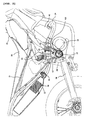
- FIG. 2 is an enlarged side view of a portion including the engine 20 and the exhaust pipe 24 of the motorcycle 10.
- FIG. 3 is a schematic plan view corresponding to FIG. 2, and
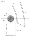
- FIG. 4 is a cross sectional view taken along the line IV-IV in FIG. 3.
- the exhaust pipe 24 includes a first exhaust pipe 124, a second exhaust pipe 224, and a third exhaust pipe 324 connected together. Through the first exhaust pipe 124 to third exhaust pipe 324, exhaust gas will be delivered from the engine 20 to the silencer 22. To facilitate the gas delivery through a predetermined route, these exhaust pipes each have a certain radius of curvature.
- the first exhaust pipe 124 is connected to the exhaust opening 42 of the engine at the inlet of the exhaust pipe 124 and extends forward, and is curved and further extends rearward.
- the second exhaust pipe 224 is connected to an outlet of the first exhaust pipe 124 and extends rearward.
- a middle portion of the second exhaust pipe 224 has a larger diameter.
- the third exhaust pipe 324 is connected to an outlet of the second exhaust pipe 224 and extends rearward.
- An outlet of the third exhaust pipe 324 is connected to an inlet of the silencer 22.
- first exhaust pipe 124, second exhaust pipe 224, and third exhaust pipe 324 can be formed together into a single piece.
- the motorcycle in accordance with this embodiment further includes a silencer 22 connected to a rear end of the third exhaust pipe 324.
- a main catalyst 58 is disposed for purifying exhaust gas.
- a pre-catalyst 60 is disposed for raising the temperature of exhaust gas.
- the pre-catalyst 60 is positioned forwardly of the main catalyst 58.
- the main catalyst 58 is a known device for purifying exhaust gas. Since the sole use of the main catalyst 58 results in insufficient purification of exhaust gas, the pre-catalyst 60 is provided additionally.
- the pre-catalyst 60 uses a catalyst reducing device including platinum, rhodium or the like to deoxidize or oxidize toxic substances contained in exhaust gas.
- the pre-catalyst 60 exhibits low reducing ability at ambient temperatures. Specifically, immediately after the start of the engine 20, it exhibits substantially no reducing ability. Hence, the pre-catalyst 60 is positioned closer to the exhaust opening 42 of the engine 20 to thereby raise the temperature of exhaust gas.
- the exhaust pipe 24 is positioned by the side of the engine 20 so as to extend rearward and inward, and passes between the engine 20 and the main frame 12.
- the pre-catalyst 60 is disposed in a portion of the exhaust pipe 24 on the vehicle side of the main frame 12.
- the exhaust pipe 24 extends forward from the exhaust opening 42 of the engine 20 and is curved and further extends rearward.
- the exhaust pipe 24 passes above the crankcase 38 of the engine 20 and by the inside of the main frame 12.
- the exhaust pipe 24 further passes between the inside of the main frame 12 and the rear cushion 30 and extends rearward.
- the exhaust pipe 24 is positioned by the side of the engine 20 and extends from the front side of the vehicle toward the rear to be inclined to the inside. More specifically, the exhaust pipe 24 passing around the engine 20 is located such that its center axis "A" is inclined to the inside at an angle of ⁇ relative to the direction of axis "B" in which the vehicle travels (see FIG. 3). This aims at separating the exhaust pipe 24 at high temperatures as far away from rider's leg (calf) 100 as possible.
- the pre-catalyst 60 is disposed adjacent to the crankcase 38 and in a portion of the exhaust pipe 24 above and closely behind the crankcase 38 (see FIG. 4). As a result, the pre-catalyst 60 will be positioned rearwardly of a lateral side end of the engine 20 and by the inside of the main frame 12.
- the pre-catalyst 60 since the pre-catalyst 60 is positioned proximate to the exhaust opening 42 in the exhaust pipe 24, the temperature of the pre-catalyst 60 will rise quickly. This achieves efficient purification of exhaust gas.
- the pre-catalyst 60 is positioned inside of an outside end of the main frame 12 (see FIG. 3) to be apart from the rider's leg 100. Thus, damage due to heat from the pre-catalyst 60 at high temperatures can be prevented.
- a portion of the exhaust pipe where the pre-catalyst 60 is disposed has a double-pipe structure.
- the second exhaust pipe 224 has the pre-catalyst 60 disposed therein.
- An outer pipe 25 is attached so as to cover the periphery of the second exhaust pipe 224.
- the outer pipe 25 is disposed around the second exhaust pipe 224 to define a heat insulating space 35 therebetween.
- a front end and a rear end of the outer pipe 25 are in sealing contact with the periphery of the second exhaust pipe 224.
- the heat insulating space 35 is an enclosed space.
- the air in the enclosed space will exert a heat insulation effect to insulate radiation heat from the pre-catalyst 60 at high temperatures (e.g., 900°C).
- the pre-catalyst 60 at high temperatures may cause a change in color or rust on the second exhaust pipe 224.
- the outer pipe 25 also serves to hide the second exhaust pipe 224 subjected to such change in color or the like.
- a heat shield plate 62 is attached so as to shield the outer pipe 25 described above.
- the heat shield plate 62 is composed of synthetic resin, and is secured to the main frame 12 with a bolt 64.
- the heat shield plate 62 can thus be easily attached.
- the heat shield plate 62 can be composed of any material other than synthetic resin, e.g., metal sheet.
- the heat shield plate 62 is disposed on the outside in the vehicle width direction of a portion of the exhaust pipe 24 where the pre-catalyst 60 is installed. A heat insulating space 37 is thereby defined between the exhaust pipe 24 and the heat shield plate 62. Damage due to heat from the exhaust pipe 24 can thus be prevented.
- the periphery of the pre-catalyst 60 is covered by the outer pipe 25, which is in turn shielded by the heat shield plate 62, as described above. Therefore, damage due to heat from the pre-catalyst 60 can be prevented.
- an oxygen concentration sensor 66 is installed in a portion of the exhaust pipe 24 passing through the inside of the main frame 12 (see FIG. 1).
- the pre-catalyst 60 is installed forwardly of the oxygen concentration sensor 66 in the exhaust pipe 24.
- the oxygen concentration sensor 66 detects the concentration of oxygen in exhaust gas. The detection value from the sensor 66 is used to control a mixture ratio.
- the exhaust pipe 24 is positioned between the engine 20 and the main frame 12, as seen from above.
- the catalyst (pre-catalyst 60) is positioned inside of the outside end of the main frame 12. Accordingly, the catalyst (pre-catalyst 60) is apart from rider's leg, so that damage due to heat from the exhaust pipe 24 can be prevented.
- the engine 20 has the crankcase 38 on a side in the vehicle width direction. Since the catalyst (pre-catalyst 60) is positioned above the crankcase 38, the projection of the catalyst (pre-catalyst 60) beyond an outside end of the crankcase 38 can be reduced. Thus, damage due to heat from the catalyst (pre-catalyst 60) can be prevented, and efficient purification of exhaust gas can be achieved.
- the catalyst (pre-catalyst 60) is positioned adjacent to the crankcase 38, thereby disposing the catalyst (pre-catalyst 60) closer to the exhaust opening 42.
- the temperature of the catalyst (pre-catalyst 60) will thus rise quickly.
- the motorcycle in accordance with this embodiment includes the oxygen concentration sensor 66 installed in the exhaust pipe 24.
- the catalyst (pre-catalyst 60) is installed forwardly of the oxygen concentration sensor 66.
- the catalyst (pre-catalyst 60) can be disposed closer to the exhaust opening 42.
- the temperature of the catalyst (pre-catalyst 60) will rise quickly, which achieves efficient purification of exhaust gas.
- the exhaust pipe 24 is positioned by the side of the engine 20 so as to extend rearward and inward.
- the catalyst pre-catalyst 60 is thereby apart from rider's leg, so that damage due to heat from the exhaust pipe 24 can be prevented.
- the motorcycle in accordance with this embodiment includes the outer pipe 25 covering the periphery of a portion of the exhaust pipe 24 where the catalyst (pre-catalyst 60) is installed. As a result, the heat insulating space 35 is defined between the exhaust pipe 24 and the outer pipe 25. Damage due to heat from the exhaust pipe 24 can thus be prevented.
- the heat shield plate 62 is arranged on the outside in the vehicle width direction of a portion of the exhaust pipe 24 where the catalyst (pre-catalyst 60) is installed. As a result, the heat insulating space 37 is defined between the exhaust pipe 24 and the heat shield plate 62. Damage due to heat from the exhaust pipe 24 can thus be prevented.
- the motorcycle in accordance with this embodiment further includes the outer pipe 25 covering the periphery of a portion of the exhaust pipe 24 where the catalyst (pre-catalyst 60) is installed.
- the outer pipe 25 is in turn shielded by the heat shield plate 62. Thus, damage due to heat from the exhaust pipe 24 can be prevented.
- the heat shield plate 62 is attached to the main frame 12. This facilitates the attachment of the heat shield plate 62.
- the catalyst includes the pre-catalyst 60 for raising the temperature of exhaust gas, and the main catalyst 58 positioned downstream of the pre-catalyst 60 for purifying the exhaust gas.
- the pre-catalyst 60 is disposed in the exhaust pipe 24, and the main catalyst 58 is disposed in the silencer 22.
- the temperature of exhaust gas can be raised through the pre-catalyst 60, and purification of exhaust gas can be credibly achieved through the main catalyst 58.
- a first embodiment providing a motorcycle including: a main frame extending longitudinally of the vehicle; an engine mounted to the main frame and having an exhaust opening disposed therein; an exhaust pipe extending forward from the exhaust opening and being curved and further extending rearward; and a catalyst disposed in the exhaust pipe, in which the exhaust pipe is positioned between the engine and the main frame, as seen from above, and the catalyst is positioned inside of an outside end of the main frame.
- the engine has a crankcase on one side in a vehicle width direction, and the catalyst is positioned above the crankcase.
- the catalyst is positioned adjacent to the crankcase.
- an oxygen concentration sensor is provided which is installed in the exhaust pipe, and in which the catalyst is installed forwardly of the oxygen concentration sensor.
- the exhaust pipe is positioned by the side of the engine so as to extend rearward and inward.
- an outer pipe is provided which covers the periphery of a portion of the exhaust pipe where the catalyst is installed.
- a heat shield plate is disposed on the outside in a vehicle width direction of a portion of the exhaust pipe where the catalyst is installed.
- an outer pipe is provided which covers the periphery of the portion of the exhaust pipe where the catalyst is installed, in which the heat shield plate shields the outer pipe.
- the heat shield plate is attached to the main frame.
- a silencer which is connected to a rear end of the exhaust pipe, wherein the catalyst includes: a pre-catalyst for raising the temperature of exhaust gas; and a main catalyst positioned downstream of the pre-catalyst for purifying the exhaust gas, in which the pre-catalyst is disposed in the exhaust pipe, and the main catalyst is disposed in the silencer.
- a pre-catalyst is disposed in an exhaust pipe to purify exhaust gas. Further, the pre-catalyst is apart from rider's leg, so that damage due to heat from the exhaust pipe can be prevented.
- a motorcycle comprising: a main frame extending longitudinally of the vehicle; an engine mounted on the main frame and having an exhaust opening disposed therein; an exhaust pipe extending forward from the exhaust opening and being curved and further extending rearward; and a catalyst disposed in the exhaust pipe, wherein the exhaust pipe is positioned between the engine and the main frame, as seen from above, and the catalyst is positioned inside of an outside end of the main frame.
- the engine has a crankcase on one side in a vehicle width direction, and the catalyst is positioned above the crankcase.
- the catalyst is positioned adjacent to the crankcase.
- the motorcycle may further comprise an oxygen concentration sensor installed in the exhaust pipe, wherein the catalyst is installed forwardly of the oxygen concentration sensor.
- the exhaust pipe may be positioned by the side of the engine so as to extend rearward and inward.
- the motorcycle may further comprise an outer pipe covering the periphery of a portion of the exhaust pipe where the catalyst is installed.
- a heat shield plate is disposed on the outside in a vehicle width direction of a portion of the exhaust pipe where the catalyst is installed.
- the motorcycle may further comprise an outer pipe covering the periphery of the portion of the exhaust pipe where the catalyst is installed, wherein the heat shield plate shields the outer pipe.
- the heat shield plate is attached to the main frame.
- the motorcycle further comprises a silencer connected to a rear end of the exhaust pipe, wherein the catalyst includes: a pre-catalyst for raising the temperature of exhaust gas; and a main catalyst positioned downstream of the pre-catalyst for purifying the exhaust gas, wherein the pre-catalyst is disposed in the exhaust pipe, and the main catalyst is disposed in the silencer.
- the catalyst includes: a pre-catalyst for raising the temperature of exhaust gas; and a main catalyst positioned downstream of the pre-catalyst for purifying the exhaust gas, wherein the pre-catalyst is disposed in the exhaust pipe, and the main catalyst is disposed in the silencer.
- a motorcycle 10 which includes a main frame 12 extending longitudinally of the vehicle; an engine 20 mounted on the main frame 12 and having an exhaust opening 42 disposed therein; an exhaust pipe 24 extending forward from the exhaust opening 42 and being curved and further extending rearward; and a pre-catalyst 60 disposed in the exhaust pipe 24.
- the exhaust pipe 24 is positioned between the engine 20 and the main frame 12, as seen from above.
- the pre-catalyst 60 is positioned inside of an outside end of the main frame 12.
Landscapes
- Engineering & Computer Science (AREA)
- Mechanical Engineering (AREA)
- Chemical & Material Sciences (AREA)
- Combustion & Propulsion (AREA)
- General Engineering & Computer Science (AREA)
- Exhaust Silencers (AREA)
- Exhaust Gas After Treatment (AREA)
- Automatic Cycles, And Cycles In General (AREA)
- Filters For Electric Vacuum Cleaners (AREA)
- Cleaning Of Streets, Tracks, Or Beaches (AREA)
- Glass Compositions (AREA)
- Exhaust Gas Treatment By Means Of Catalyst (AREA)
Abstract
Description
- The present invention relates to a straddle-type vehicle, in particular a motorcycle, in which an exhaust pipe passes on a side of an engine, and a catalyst is disposed in the exhaust pipe to purify exhaust gas.
- Exhaust purifying devices for motorcycles in which a main catalyst is disposed in a silencer and a pre-catalyst is disposed in an exhaust pipe are known. Exhaust gas can be purified when it passes through the main catalyst and the pre-catalyst. (See Patent Document 1, for example.)
- Patent Document 1 discloses an exhaust purifying device for a motorcycle including: an exhaust pipe extending forward from an exhaust opening of an engine and extending downward and further extending rearward; and a pre-catalyst disposed in the exhaust pipe. The exhaust pipe passes by one side of a cylinder body. The pre-catalyst is positioned on the one side of the cylinder body.
Patent Document 1:JP-A-2006-9648 - The sole use of the main catalyst installed in the muffler is often insufficient for the purification of exhaust gas due to a lower temperature. This is because the main catalyst is usually far away from the exhaust opening, so that the temperature of exhaust gas will lower by the time the exhaust gas reaches the catalyst. The additional use of the pre-catalyst aims at smooth purification of exhaust gas. However, efficient purification of exhaust gas will not be achieved if the temperature of exhaust gas does not increase. Meanwhile, the pre-catalyst will typically have high interior temperatures of 800 to 900°C, for example. It is thus critical to protect rider's leg against radiation heat from a portion of the exhaust pipe where the pre-catalyst is installed.
- Unfortunately, according to Patent Document 1, the pre-catalyst is arranged near the cylinder body for earlier activation of exhaust gas. As a result, the pre-catalyst will be disposed proximate to rider's leg. Thus, measures must be taken against damage due to heat. When the pre-catalyst is installed in a rear part of the exhaust pipe (a position closer to the silencer), efficient purification will not be achieved. When a heat insulating plate is provided on the outside of the exhaust pipe, the insulating plate itself may become very hot, or in some cases, melt depending on the material used.
- Therefore, it is the objective of the present invention to provide a straddle-type vehicle, in particular a motorcycle, in which a pre-catalyst is disposed in an exhaust pipe to purify exhaust gas, and the pre-catalyst is installed away from rider's leg.
- This objective is solved in an inventive manner by a straddle-type vehicle, in particular a motorcycle, comprising: a main frame extending longitudinally of the vehicle; an engine mounted on the main frame, and having an exhaust opening disposed therein; an exhaust pipe extending forward from the exhaust opening and being curved and further extending rearward; and a catalyst being disposed in the exhaust pipe, wherein the exhaust pipe is positioned between the engine and the main frame, as seen from above.
- Preferably, the catalyst is positioned at an inside of the main frame.
- Further, preferably the engine has a crankcase on one side in a vehicle width direction, and the catalyst is positioned above the crankcase.
- Still further, preferably the catalyst is positioned adjacent to the crankcase.
- Yet further, preferably the catalyst is positioned rearwardly of a lateral side end of the engine and by the inside of the main frame.
- According to a further preferred embodiment, the straddle-type vehicle further comprises an oxygen concentration sensor installed in the exhaust pipe, wherein the catalyst is installed forwardly of the oxygen concentration sensor.
- Furthermore, the exhaust pipe may be positioned by the side of the engine so as to extend rearwardly and inwardly.
- Beneficially, the exhaust pipe passing around the engine is located such that its center axis is inclined to the inside at an angle relative to the traveling direction of the vehicle.
- Further, beneficially the straddle-type vehicle further comprises an outer pipe covering the periphery of a portion of the exhaust pipe where the catalyst is installed.
- Yet further, beneficially a heat shield plate is disposed on the outside in a vehicle width direction of a portion of the exhaust pipe where the catalyst is installed.
- Therein, the heat shield plate may shield the outer pipe.
- Likewise, the heat shield plate may be attached to the main frame.
- According to a further preferred embodiment, the straddle-type vehicle further comprises a silencer connected to a rear end of the exhaust pipe, wherein the catalyst includes a pre-catalyst for raising the temperature of exhaust gas; and a main catalyst positioned downstream of the pre-catalyst for purifying the exhaust gas, and wherein the pre-catalyst is disposed in the exhaust pipe, and the main catalyst is disposed in the silencer.
- In the following, the present invention is explained in greater detail with respect to several embodiments thereof in conjunction with the accompanying drawings, wherein:
- FIG. 1
- is a schematic side view illustrating the general structure of a motorcycle to which the present teaching is applied,
- FIG. 2
- is an enlarged view of a portion of FIG. 1,
- FIG. 3
- is a plan view of a portion including an engine and an exhaust pipe of the motorcycle shown in FIG. 1, and
- FIG. 4
- is a cross sectional view taken along the line IV-IV of FIG. 3.
-
- 1: motorcycle
- 12: main frame
- 14: head pipe
- 16: front fork
- 18: front wheel
- 20: engine
- 22: silencer
- 24: exhaust pipe
- 25: outer pipe
- 26: fuel tank
- 28: seat
- 30: rear cushion
- 31: seat rail
- 32: pivot shaft
- 33: backstay
- 34: rear arm
- 38: crankcase
- 40: cylinder body
- 42: exhaust opening
- 48: handlebar
- 58: main catalyst
- 60: pre-catalyst
- 62: heat shield plate
- 100: rider's leg
- 124: first exhaust pipe
- 224: second exhaust pipe
- 324: third exhaust pipe
- An embodiment embodying the present teaching will be described below with reference to the drawings.
- FIG. 1 is a side view illustrating the general structure of a motorcycle in accordance with an embodiment.
- A
motorcycle 10 includes ahead pipe 14 belowhandlebars 48, and a pair of left and rightmain frames 12 extending from thehead pipe 14 longitudinally of the vehicle. To thehead pipe 14,front forks 16 are attached in a manner to steer to the left and right. Afront wheel 18 is attached to lower parts of thefront forks 16. To themain frame 12, anengine 20 is mounted. Theengine 20 has anexhaust pipe 24 attached thereto through which exhaust gas can flow into asilencer 22. - From a middle portion of each
main frame 12, aseat rail 31 and abackstay 33 extend upward and rearward. The middle portion of themain frame 12, theseat rail 31, and thebackstay 33 are coupled together to form a generally triangular framework. From a lower part of themain frame 12, arear arm 34 extends. Therear arm 34 is attached for up-and-down pivotal movement about apivot shaft 32 via arear cushion 30. Arear wheel 36 is attached to a rear part of therear arm 34. - On a generally central upper portion of the vehicle, a
fuel tank 26 and aseat 28 are attached in a manner to be supported with themain frames 12 and the seat rails 31. - The
engine 20 includes acrankcase 38 and acylinder body 40. Theengine 20 is secured to themain frames 12 with securing means such as bolts. Theengine 20 is a four-stroke engine. Theengine 20 has anexhaust opening 42 in a front part of theengine 20. Theexhaust pipe 24 is attached to theexhaust opening 42. - The
exhaust pipe 24 extends forward from theexhaust opening 42 and is curved and further extends rearward. As seen from above, theexhaust pipe 24 is positioned between theengine 20 and themain frame 12. Thesilencer 22 is connected to an outlet of theexhaust pipe 24 in front of therear wheel 36 and below theseat 28. Theexhaust pipe 24 and thesilencer 22 respectively haveprotectors engine 20, there is disposed aradiator 44. Anair cleaner 46 is disposed behind theengine 20 and below theseat 28. - The
exhaust pipe 24 is attached to theexhaust opening 42 of theengine 20. Thesilencer 22 is secured to thebackstay 33 with a bolt. In a front portion of the vehicle, afront turn signal 50 is provided below the handlebars 48. Afront fender 52 is attached to the insides of the left and rightfront forks 16. In an upper rear portion of the vehicle, there are provided arear fender 54 and arear turn signal 56. - Around an output shaft of the
engine 20 and therear wheel 36, a chain (not shown) is wound to transmit power. - FIG. 2 is an enlarged side view of a portion including the
engine 20 and theexhaust pipe 24 of themotorcycle 10. FIG. 3 is a schematic plan view corresponding to FIG. 2, and FIG. 4 is a cross sectional view taken along the line IV-IV in FIG. 3. - The
exhaust pipe 24 includes afirst exhaust pipe 124, asecond exhaust pipe 224, and athird exhaust pipe 324 connected together. Through thefirst exhaust pipe 124 tothird exhaust pipe 324, exhaust gas will be delivered from theengine 20 to thesilencer 22. To facilitate the gas delivery through a predetermined route, these exhaust pipes each have a certain radius of curvature. - The
first exhaust pipe 124 is connected to theexhaust opening 42 of the engine at the inlet of theexhaust pipe 124 and extends forward, and is curved and further extends rearward. Thesecond exhaust pipe 224 is connected to an outlet of thefirst exhaust pipe 124 and extends rearward. A middle portion of thesecond exhaust pipe 224 has a larger diameter. Thethird exhaust pipe 324 is connected to an outlet of thesecond exhaust pipe 224 and extends rearward. An outlet of thethird exhaust pipe 324 is connected to an inlet of thesilencer 22. - It is understood that the
first exhaust pipe 124,second exhaust pipe 224, andthird exhaust pipe 324 can be formed together into a single piece. - The motorcycle in accordance with this embodiment further includes a
silencer 22 connected to a rear end of thethird exhaust pipe 324. In thesilencer 22, amain catalyst 58 is disposed for purifying exhaust gas. In thesecond exhaust pipe 224, a pre-catalyst 60 is disposed for raising the temperature of exhaust gas. The pre-catalyst 60 is positioned forwardly of themain catalyst 58. Themain catalyst 58 is a known device for purifying exhaust gas. Since the sole use of themain catalyst 58 results in insufficient purification of exhaust gas, the pre-catalyst 60 is provided additionally. - Description will now be given to the pre-catalyst 60.
- The pre-catalyst 60 uses a catalyst reducing device including platinum, rhodium or the like to deoxidize or oxidize toxic substances contained in exhaust gas. The pre-catalyst 60 exhibits low reducing ability at ambient temperatures. Specifically, immediately after the start of the
engine 20, it exhibits substantially no reducing ability. Hence, the pre-catalyst 60 is positioned closer to theexhaust opening 42 of theengine 20 to thereby raise the temperature of exhaust gas. - In this embodiment, the
exhaust pipe 24 is positioned by the side of theengine 20 so as to extend rearward and inward, and passes between theengine 20 and themain frame 12. The pre-catalyst 60 is disposed in a portion of theexhaust pipe 24 on the vehicle side of themain frame 12. - As shown in FIGs. 2 and 3, the
exhaust pipe 24 extends forward from theexhaust opening 42 of theengine 20 and is curved and further extends rearward. Theexhaust pipe 24 passes above thecrankcase 38 of theengine 20 and by the inside of themain frame 12. Theexhaust pipe 24 further passes between the inside of themain frame 12 and therear cushion 30 and extends rearward. - The
exhaust pipe 24 is positioned by the side of theengine 20 and extends from the front side of the vehicle toward the rear to be inclined to the inside. More specifically, theexhaust pipe 24 passing around theengine 20 is located such that its center axis "A" is inclined to the inside at an angle of θ relative to the direction of axis "B" in which the vehicle travels (see FIG. 3). This aims at separating theexhaust pipe 24 at high temperatures as far away from rider's leg (calf) 100 as possible. - The pre-catalyst 60 is disposed adjacent to the
crankcase 38 and in a portion of theexhaust pipe 24 above and closely behind the crankcase 38 (see FIG. 4). As a result, the pre-catalyst 60 will be positioned rearwardly of a lateral side end of theengine 20 and by the inside of themain frame 12. - In this embodiment, since the pre-catalyst 60 is positioned proximate to the
exhaust opening 42 in theexhaust pipe 24, the temperature of the pre-catalyst 60 will rise quickly. This achieves efficient purification of exhaust gas. In addition, the pre-catalyst 60 is positioned inside of an outside end of the main frame 12 (see FIG. 3) to be apart from the rider'sleg 100. Thus, damage due to heat from the pre-catalyst 60 at high temperatures can be prevented. - In this embodiment, a portion of the exhaust pipe where the pre-catalyst 60 is disposed has a double-pipe structure.
- As shown in FIG. 3, the
second exhaust pipe 224 has the pre-catalyst 60 disposed therein. Anouter pipe 25 is attached so as to cover the periphery of thesecond exhaust pipe 224. Theouter pipe 25 is disposed around thesecond exhaust pipe 224 to define aheat insulating space 35 therebetween. A front end and a rear end of theouter pipe 25 are in sealing contact with the periphery of thesecond exhaust pipe 224. Thus, theheat insulating space 35 is an enclosed space. - Due to this
outer pipe 25, the air in the enclosed space will exert a heat insulation effect to insulate radiation heat from the pre-catalyst 60 at high temperatures (e.g., 900°C). The pre-catalyst 60 at high temperatures may cause a change in color or rust on thesecond exhaust pipe 224. Theouter pipe 25 also serves to hide thesecond exhaust pipe 224 subjected to such change in color or the like. - In this embodiment, a
heat shield plate 62 is attached so as to shield theouter pipe 25 described above. Specifically, theheat shield plate 62 is composed of synthetic resin, and is secured to themain frame 12 with abolt 64. Theheat shield plate 62 can thus be easily attached. Theheat shield plate 62 can be composed of any material other than synthetic resin, e.g., metal sheet. - The
heat shield plate 62 is disposed on the outside in the vehicle width direction of a portion of theexhaust pipe 24 where the pre-catalyst 60 is installed. Aheat insulating space 37 is thereby defined between theexhaust pipe 24 and theheat shield plate 62. Damage due to heat from theexhaust pipe 24 can thus be prevented. - The periphery of the pre-catalyst 60 is covered by the
outer pipe 25, which is in turn shielded by theheat shield plate 62, as described above. Therefore, damage due to heat from the pre-catalyst 60 can be prevented. - In this embodiment, an
oxygen concentration sensor 66 is installed in a portion of theexhaust pipe 24 passing through the inside of the main frame 12 (see FIG. 1). The pre-catalyst 60 is installed forwardly of theoxygen concentration sensor 66 in theexhaust pipe 24. - The
oxygen concentration sensor 66 detects the concentration of oxygen in exhaust gas. The detection value from thesensor 66 is used to control a mixture ratio. - As described above, in this embodiment, the
exhaust pipe 24 is positioned between theengine 20 and themain frame 12, as seen from above. The catalyst (pre-catalyst 60) is positioned inside of the outside end of themain frame 12. Accordingly, the catalyst (pre-catalyst 60) is apart from rider's leg, so that damage due to heat from theexhaust pipe 24 can be prevented. - The
engine 20 has thecrankcase 38 on a side in the vehicle width direction. Since the catalyst (pre-catalyst 60) is positioned above thecrankcase 38, the projection of the catalyst (pre-catalyst 60) beyond an outside end of thecrankcase 38 can be reduced. Thus, damage due to heat from the catalyst (pre-catalyst 60) can be prevented, and efficient purification of exhaust gas can be achieved. - The catalyst (pre-catalyst 60) is positioned adjacent to the
crankcase 38, thereby disposing the catalyst (pre-catalyst 60) closer to theexhaust opening 42. The temperature of the catalyst (pre-catalyst 60) will thus rise quickly. - The motorcycle in accordance with this embodiment includes the
oxygen concentration sensor 66 installed in theexhaust pipe 24. The catalyst (pre-catalyst 60) is installed forwardly of theoxygen concentration sensor 66. Thus, the catalyst (pre-catalyst 60) can be disposed closer to theexhaust opening 42. Thus, the temperature of the catalyst (pre-catalyst 60) will rise quickly, which achieves efficient purification of exhaust gas. - The
exhaust pipe 24 is positioned by the side of theengine 20 so as to extend rearward and inward. The catalyst (pre-catalyst 60) is thereby apart from rider's leg, so that damage due to heat from theexhaust pipe 24 can be prevented. - The motorcycle in accordance with this embodiment includes the
outer pipe 25 covering the periphery of a portion of theexhaust pipe 24 where the catalyst (pre-catalyst 60) is installed. As a result, theheat insulating space 35 is defined between theexhaust pipe 24 and theouter pipe 25. Damage due to heat from theexhaust pipe 24 can thus be prevented. - The
heat shield plate 62 is arranged on the outside in the vehicle width direction of a portion of theexhaust pipe 24 where the catalyst (pre-catalyst 60) is installed. As a result, theheat insulating space 37 is defined between theexhaust pipe 24 and theheat shield plate 62. Damage due to heat from theexhaust pipe 24 can thus be prevented. - The motorcycle in accordance with this embodiment further includes the
outer pipe 25 covering the periphery of a portion of theexhaust pipe 24 where the catalyst (pre-catalyst 60) is installed. Theouter pipe 25 is in turn shielded by theheat shield plate 62. Thus, damage due to heat from theexhaust pipe 24 can be prevented. - The
heat shield plate 62 is attached to themain frame 12. This facilitates the attachment of theheat shield plate 62. - The catalyst includes the pre-catalyst 60 for raising the temperature of exhaust gas, and the
main catalyst 58 positioned downstream of the pre-catalyst 60 for purifying the exhaust gas. The pre-catalyst 60 is disposed in theexhaust pipe 24, and themain catalyst 58 is disposed in thesilencer 22. Thus, the temperature of exhaust gas can be raised through the pre-catalyst 60, and purification of exhaust gas can be credibly achieved through themain catalyst 58. - The description above discloses (amongst others), in order to achieve the foregoing object, a first embodiment providing a motorcycle including: a main frame extending longitudinally of the vehicle; an engine mounted to the main frame and having an exhaust opening disposed therein; an exhaust pipe extending forward from the exhaust opening and being curved and further extending rearward; and a catalyst disposed in the exhaust pipe, in which the exhaust pipe is positioned between the engine and the main frame, as seen from above, and the catalyst is positioned inside of an outside end of the main frame.
- Further, according to a second embodiment, the engine has a crankcase on one side in a vehicle width direction, and the catalyst is positioned above the crankcase.
- Further, according to a third embodiment, the catalyst is positioned adjacent to the crankcase.
- Further, according to a fourth embodiment, an oxygen concentration sensor is provided which is installed in the exhaust pipe, and in which the catalyst is installed forwardly of the oxygen concentration sensor.
- Further, according to a fifth embodiment, the exhaust pipe is positioned by the side of the engine so as to extend rearward and inward.
- Further, according to a sixth embodiment, an outer pipe is provided which covers the periphery of a portion of the exhaust pipe where the catalyst is installed.
- Further, according to a seventh embodiment, a heat shield plate is disposed on the outside in a vehicle width direction of a portion of the exhaust pipe where the catalyst is installed.
- Further, according to an eighth embodiment, an outer pipe is provided which covers the periphery of the portion of the exhaust pipe where the catalyst is installed, in which the heat shield plate shields the outer pipe.
- Further, according to a ninth embodiment, the heat shield plate is attached to the main frame.
- Further, according to a tenth embodiment, a silencer is provided which is connected to a rear end of the exhaust pipe, wherein the catalyst includes: a pre-catalyst for raising the temperature of exhaust gas; and a main catalyst positioned downstream of the pre-catalyst for purifying the exhaust gas, in which the pre-catalyst is disposed in the exhaust pipe, and the main catalyst is disposed in the silencer.
- According to the present effect of the present teaching, a pre-catalyst is disposed in an exhaust pipe to purify exhaust gas. Further, the pre-catalyst is apart from rider's leg, so that damage due to heat from the exhaust pipe can be prevented.
- The description above further discloses, according to a preferred first aspect, a motorcycle comprising: a main frame extending longitudinally of the vehicle; an engine mounted on the main frame and having an exhaust opening disposed therein; an exhaust pipe extending forward from the exhaust opening and being curved and further extending rearward; and a catalyst disposed in the exhaust pipe, wherein the exhaust pipe is positioned between the engine and the main frame, as seen from above, and the catalyst is positioned inside of an outside end of the main frame.
- Further, according to a preferred second aspect, the engine has a crankcase on one side in a vehicle width direction, and the catalyst is positioned above the crankcase.
- Further, according to a preferred third aspect, the catalyst is positioned adjacent to the crankcase.
- Further, according to a preferred fourth aspect, the motorcycle may further comprise an oxygen concentration sensor installed in the exhaust pipe, wherein the catalyst is installed forwardly of the oxygen concentration sensor.
- Further, according to a preferred fifth aspect, the exhaust pipe may be positioned by the side of the engine so as to extend rearward and inward.
- Further, according to a preferred sixth aspect, the motorcycle may further comprise an outer pipe covering the periphery of a portion of the exhaust pipe where the catalyst is installed.
- Further, according to a preferred seventh aspect, a heat shield plate is disposed on the outside in a vehicle width direction of a portion of the exhaust pipe where the catalyst is installed.
- Further, according to a preferred eighth aspect, the motorcycle may further comprise an outer pipe covering the periphery of the portion of the exhaust pipe where the catalyst is installed, wherein the heat shield plate shields the outer pipe.
- Further, according to a preferred ninth aspect, the heat shield plate is attached to the main frame.
- Further, according to a preferred tenth aspect, the motorcycle further comprises a silencer connected to a rear end of the exhaust pipe, wherein the catalyst includes: a pre-catalyst for raising the temperature of exhaust gas; and a main catalyst positioned downstream of the pre-catalyst for purifying the exhaust gas, wherein the pre-catalyst is disposed in the exhaust pipe, and the main catalyst is disposed in the silencer.
- Further, according to a particularly preferred embodiment, in order to provide a motorcycle in which a pre-catalyst is disposed in an exhaust pipe to purify exhaust gas, and the pre-catalyst is installed away from rider's leg, there is disclosed a
motorcycle 10 which includes amain frame 12 extending longitudinally of the vehicle; anengine 20 mounted on themain frame 12 and having anexhaust opening 42 disposed therein; anexhaust pipe 24 extending forward from theexhaust opening 42 and being curved and further extending rearward; and a pre-catalyst 60 disposed in theexhaust pipe 24. Theexhaust pipe 24 is positioned between theengine 20 and themain frame 12, as seen from above. The pre-catalyst 60 is positioned inside of an outside end of themain frame 12.
Claims (13)
- Straddle-type vehicle, in particular motorcycle (10) comprising:a main frame (12) extending longitudinally of the vehicle;an engine (20) mounted on the main frame (12), and having an exhaust opening (42) disposed therein;an exhaust pipe (24) extending forward from the exhaust opening (42) and being curved and further extending rearward; anda catalyst (60) being disposed in the exhaust pipe (24),wherein the exhaust pipe is positioned between the engine (20) and the main frame (12), as seen from above.
- Straddle-type vehicle according to claim 1, wherein the catalyst (60) is positioned at an inside of the main frame.
- Straddle-type vehicle according to claim 1 or 2, wherein the engine (20) has a crankcase (38) on one side in a vehicle width direction, and the catalyst (60) is positioned above the crankcase (38).
- Straddle-type vehicle according to claim 3, wherein the catalyst (60) is positioned adjacent to the crankcase (38).
- Straddle-type vehicle according to claim 3 or 4, wherein the catalyst (60) is positioned rearwardly of a lateral side end of the engine (20) and by the inside of the main frame (12).
- Straddle-type vehicle according to one of the claims 1 to 5, further comprising an oxygen concentration sensor (66) installed in the exhaust pipe (24); wherein the catalyst (60) is installed forwardly of the oxygen concentration sensor (66).
- Straddle-type vehicle according to one of the claims 1 to 6, wherein the exhaust pipe (24) is positioned by the side of the engine (20) so as to extend rearwardly and inwardly.
- Straddle-type vehicle according to claim 7, wherein the exhaust pipe (24) passing around the engine (20) is located such that its center axis (A) is inclined to the inside at an angle (θ) relative to the traveling direction (B) of the vehicle.
- Straddle-type vehicle according to one of the claims 1 to 8, further comprising an outer pipe (25) covering the periphery of a portion of the exhaust pipe (24) where the catalyst (60) is installed.
- Straddle-type vehicle according to one of the claims 1 to 9, wherein a heat shield plate (62) is disposed on the outside in a vehicle width direction of a portion of the exhaust pipe (24) where the catalyst (60) is installed.
- Straddle-type vehicle according to claim 10, wherein the heat shield plate (62) shields the outer pipe (25).
- Straddle-type vehicle according to claim 10 or 11, wherein the heat shield plate (62) is attached to the main frame (12).
- Straddle-type vehicle according to one of the claims 1 to 12, further comprising a silencer (22) connected to a rear end of the exhaust pipe (24), wherein the catalyst includes a pre-catalyst (60) for raising the temperature of exhaust gas; and a main catalyst positioned downstream of the pre-catalyst (60) for purifying the exhaust gas, and wherein the pre-catalyst (60) is disposed in the exhaust pipe (24), and the main catalyst is disposed in the silencer (22).
Applications Claiming Priority (1)
| Application Number | Priority Date | Filing Date | Title |
|---|---|---|---|
| JP2006245349A JP2008064068A (en) | 2006-09-11 | 2006-09-11 | Motorcycle |
Publications (2)
| Publication Number | Publication Date |
|---|---|
| EP1897794A1 true EP1897794A1 (en) | 2008-03-12 |
| EP1897794B1 EP1897794B1 (en) | 2009-06-10 |
Family
ID=38834974
Family Applications (1)
| Application Number | Title | Priority Date | Filing Date |
|---|---|---|---|
| EP07017689A Active EP1897794B1 (en) | 2006-09-11 | 2007-09-10 | Straddle-type vehicle |
Country Status (6)
| Country | Link |
|---|---|
| US (1) | US20080060864A1 (en) |
| EP (1) | EP1897794B1 (en) |
| JP (1) | JP2008064068A (en) |
| AT (1) | ATE433409T1 (en) |
| DE (1) | DE602007001267D1 (en) |
| ES (1) | ES2327073T3 (en) |
Cited By (3)
| Publication number | Priority date | Publication date | Assignee | Title |
|---|---|---|---|---|
| EP1980737A1 (en) | 2007-04-09 | 2008-10-15 | Yamaha Hatsudoki Kabushiki Kaisha | Vehicle |
| CN110816733A (en) * | 2018-08-08 | 2020-02-21 | 铃木株式会社 | Motorcycle with a motorcycle body |
| EP3947932A2 (en) * | 2019-03-25 | 2022-02-09 | TVS Motor Company Limited | A motor vehicle comprising a combustion engine and exhaust system |
Families Citing this family (13)
| Publication number | Priority date | Publication date | Assignee | Title |
|---|---|---|---|---|
| US20080296878A1 (en) * | 2007-06-01 | 2008-12-04 | John Doug Pruit | Motorcycle Exhaust Pipe Guard and Mounting Bracket |
| JP2009051323A (en) * | 2007-08-24 | 2009-03-12 | Yamaha Motor Co Ltd | Motorcycle |
| JP5093668B2 (en) * | 2008-03-18 | 2012-12-12 | 本田技研工業株式会社 | Exhaust structure of motorcycle |
| JP5142781B2 (en) * | 2008-03-27 | 2013-02-13 | 本田技研工業株式会社 | Motorcycle |
| JP5147498B2 (en) * | 2008-03-31 | 2013-02-20 | 本田技研工業株式会社 | Motorcycle body frame |
| EP2211036B1 (en) * | 2009-01-26 | 2011-05-04 | Yamaha Motor Europe N.V. | Motorcycle equipped with an exhaust gas purifying apparatus with improved layout |
| JP5406064B2 (en) * | 2010-01-29 | 2014-02-05 | 本田技研工業株式会社 | Exhaust system for motorcycles |
| JP6031244B2 (en) * | 2012-03-28 | 2016-11-24 | 本田技研工業株式会社 | Exhaust device for saddle riding type vehicle |
| JP7338145B2 (en) * | 2018-11-26 | 2023-09-05 | スズキ株式会社 | straddle-type vehicle |
| WO2020217661A1 (en) * | 2019-04-24 | 2020-10-29 | ヤマハ発動機株式会社 | Saddle-type vehicle |
| JP6982033B2 (en) * | 2019-09-12 | 2021-12-17 | 本田技研工業株式会社 | Saddle-type vehicle |
| JP7601045B2 (en) * | 2022-04-05 | 2024-12-17 | トヨタ自動車株式会社 | Catalytic converter |
| JP7819572B2 (en) | 2022-05-02 | 2026-02-25 | スズキ株式会社 | Saddle-type vehicle |
Citations (5)
| Publication number | Priority date | Publication date | Assignee | Title |
|---|---|---|---|---|
| US4881614A (en) * | 1987-02-16 | 1989-11-21 | Honda Giken Kogyo Kabushiki Kaisha | Motorcycle |
| JPH03237212A (en) * | 1990-02-14 | 1991-10-23 | Suzuki Motor Corp | Heat shielding cover for exhaust pipe and muffler of engine |
| JPH0932547A (en) * | 1995-07-21 | 1997-02-04 | Suzuki Motor Corp | Exhaust pipe cover structure for motorcycles |
| JP2002303132A (en) * | 2001-03-30 | 2002-10-18 | Suzuki Motor Corp | Motorcycle |
| EP1744025A2 (en) * | 2005-07-12 | 2007-01-17 | Yamaha Hatsudoki Kabushiki Kaisha | Saddle-type vehicle |
Family Cites Families (29)
| Publication number | Priority date | Publication date | Assignee | Title |
|---|---|---|---|---|
| JPS5793616A (en) * | 1980-12-03 | 1982-06-10 | Honda Motor Co Ltd | Exhaust purifier for internal combustion engine |
| US4475622A (en) * | 1981-11-25 | 1984-10-09 | Honda Giken Kogyo Kabushiki Kaisha | Exhaust system for motor vehicles |
| US4437306A (en) * | 1981-11-25 | 1984-03-20 | Honda Giken Kogyo Kabushiki Kaisha | Exhaust gas cleaning device of internal combustion engine |
| US4553388A (en) * | 1981-11-30 | 1985-11-19 | Honda Giken Kogyo Kabushiki Kaisha | Exhaust gas purification apparatus for an internal combustion engine |
| JPS58106120A (en) * | 1981-12-18 | 1983-06-24 | Honda Motor Co Ltd | Exhaust gas purification device for internal combustion engines in motorcycles |
| US4632073A (en) * | 1984-05-16 | 1986-12-30 | Yamaha Hatsudoki Kabushiki Kaisha | Camshaft mounting mechanism for DOHC engine of motorcyle |
| JP3008488B2 (en) * | 1990-11-22 | 2000-02-14 | スズキ株式会社 | Secondary air supply for two-stroke engine |
| JP2966554B2 (en) * | 1991-02-22 | 1999-10-25 | ヤマハ発動機株式会社 | O2 sensor arrangement structure for exhaust system for motorcycle |
| JP3046435B2 (en) * | 1991-09-11 | 2000-05-29 | ヤマハ発動機株式会社 | Motorcycle oxygen sensor protection device |
| JP3314241B2 (en) * | 1992-04-06 | 2002-08-12 | ヤマハ発動機株式会社 | Exhaust gas purification device for motorcycle engine |
| IT1267642B1 (en) * | 1993-12-09 | 1997-02-07 | Honda Motor Co Ltd | DISCHARGE DEVICE |
| JP3257906B2 (en) * | 1994-09-05 | 2002-02-18 | 本田技研工業株式会社 | Engine exhaust purification device |
| US6141958A (en) * | 1998-12-31 | 2000-11-07 | Voss; Randy E. | Exhaust cooling system for vehicles |
| JP2000345837A (en) * | 1999-06-01 | 2000-12-12 | Honda Motor Co Ltd | Arrangement structure of exhaust pipe in vehicle |
| JP4149152B2 (en) * | 2001-09-17 | 2008-09-10 | 本田技研工業株式会社 | Arrangement structure of engine accessories in motorcycle |
| JP4057384B2 (en) * | 2002-09-26 | 2008-03-05 | 本田技研工業株式会社 | Engine mounting structure for low floor vehicles |
| US6946013B2 (en) * | 2002-10-28 | 2005-09-20 | Geo2 Technologies, Inc. | Ceramic exhaust filter |
| JP2004249774A (en) * | 2003-02-18 | 2004-09-09 | Yamaha Motor Co Ltd | Motorcycle |
| US7032563B2 (en) * | 2003-03-31 | 2006-04-25 | Honda Motor Co., Ltd. | Intake apparatus for engine |
| JP2005016511A (en) * | 2003-06-03 | 2005-01-20 | Yamaha Motor Co Ltd | Engine balancer structure |
| MY141622A (en) * | 2003-06-19 | 2010-05-31 | Yamaha Motor Co Ltd | Exhaust system for an engine |
| JP4163585B2 (en) * | 2003-09-30 | 2008-10-08 | 本田技研工業株式会社 | Motorcycle body structure |
| US7510050B2 (en) * | 2004-01-27 | 2009-03-31 | Emler Don R | Vehicle exhaust systems |
| JP2006009648A (en) * | 2004-06-24 | 2006-01-12 | Honda Motor Co Ltd | Motorcycle exhaust purification system |
| US7263826B2 (en) * | 2004-07-13 | 2007-09-04 | Sentec E&E Co., Ltd. | Muffler device with catalysts for improving purifying exhaust gas of nitrogen oxides within a motorcycle exhaust pipe |
| JP4655743B2 (en) * | 2005-04-27 | 2011-03-23 | スズキ株式会社 | Motorcycle exhaust system |
| US7334402B2 (en) * | 2005-06-17 | 2008-02-26 | Kawasaki Jukogyo Kabushiki Kaisha | Exhaust system with catalytic converter and motorcycle using the same |
| US7216612B2 (en) * | 2005-08-05 | 2007-05-15 | Yamaha Hatsudoki Kabushiki Kaisha | Internal combustion engine having cylinder formed with water jacket and vehicle provided with the same |
| JP4309876B2 (en) * | 2005-08-09 | 2009-08-05 | 川崎重工業株式会社 | Motorcycle |
-
2006
- 2006-09-11 JP JP2006245349A patent/JP2008064068A/en active Pending
-
2007
- 2007-08-30 US US11/848,067 patent/US20080060864A1/en not_active Abandoned
- 2007-09-10 DE DE602007001267T patent/DE602007001267D1/en active Active
- 2007-09-10 ES ES07017689T patent/ES2327073T3/en active Active
- 2007-09-10 EP EP07017689A patent/EP1897794B1/en active Active
- 2007-09-10 AT AT07017689T patent/ATE433409T1/en not_active IP Right Cessation
Patent Citations (5)
| Publication number | Priority date | Publication date | Assignee | Title |
|---|---|---|---|---|
| US4881614A (en) * | 1987-02-16 | 1989-11-21 | Honda Giken Kogyo Kabushiki Kaisha | Motorcycle |
| JPH03237212A (en) * | 1990-02-14 | 1991-10-23 | Suzuki Motor Corp | Heat shielding cover for exhaust pipe and muffler of engine |
| JPH0932547A (en) * | 1995-07-21 | 1997-02-04 | Suzuki Motor Corp | Exhaust pipe cover structure for motorcycles |
| JP2002303132A (en) * | 2001-03-30 | 2002-10-18 | Suzuki Motor Corp | Motorcycle |
| EP1744025A2 (en) * | 2005-07-12 | 2007-01-17 | Yamaha Hatsudoki Kabushiki Kaisha | Saddle-type vehicle |
Cited By (4)
| Publication number | Priority date | Publication date | Assignee | Title |
|---|---|---|---|---|
| EP1980737A1 (en) | 2007-04-09 | 2008-10-15 | Yamaha Hatsudoki Kabushiki Kaisha | Vehicle |
| CN110816733A (en) * | 2018-08-08 | 2020-02-21 | 铃木株式会社 | Motorcycle with a motorcycle body |
| CN110816733B (en) * | 2018-08-08 | 2021-11-05 | 铃木株式会社 | Motorcycle with a motorcycle body |
| EP3947932A2 (en) * | 2019-03-25 | 2022-02-09 | TVS Motor Company Limited | A motor vehicle comprising a combustion engine and exhaust system |
Also Published As
| Publication number | Publication date |
|---|---|
| ATE433409T1 (en) | 2009-06-15 |
| EP1897794B1 (en) | 2009-06-10 |
| US20080060864A1 (en) | 2008-03-13 |
| ES2327073T3 (en) | 2009-10-23 |
| JP2008064068A (en) | 2008-03-21 |
| DE602007001267D1 (en) | 2009-07-23 |
Similar Documents
| Publication | Publication Date | Title |
|---|---|---|
| EP1897794B1 (en) | Straddle-type vehicle | |
| JP3046435B2 (en) | Motorcycle oxygen sensor protection device | |
| JP5879064B2 (en) | Saddle riding vehicle | |
| JP4661472B2 (en) | Motorcycle cowling | |
| EP2557290B1 (en) | Exhaust pipe structure of internal combustion engine | |
| EP2463187B1 (en) | Saddle riding type vehicle | |
| US8322479B2 (en) | Covering for motorcycle exhaust tube | |
| EP1900624B1 (en) | Motorcycle with exhaust pipe comprising an oxygen concentration sensor | |
| US8783024B2 (en) | Exhaust chamber in motorcycle exhaust system | |
| CN106536885A (en) | Saddle-driven vehicle and single-cylinder 4-stroke engine unit | |
| JP5820443B2 (en) | Scooter type vehicle | |
| EP2562069B1 (en) | Saddle-riding type automotive vehicle | |
| EP2031200B1 (en) | An exhaust gas purifying apparatus for a motorcycle, a motorcycle comprising an exhaust gas purifying apparatus | |
| CN211343074U (en) | Motorcycle with a motorcycle body | |
| JP2007085235A (en) | Motorcycle exhaust muffler | |
| CN112351935B (en) | Oxygen sensor configuration structure of motorcycle | |
| JP4871107B2 (en) | Saddle riding | |
| JP6610438B2 (en) | Exhaust gas sensor layout | |
| JP3151233U (en) | Motorcycle | |
| JP2006044633A (en) | Saddle riding vehicle | |
| JP5950215B2 (en) | Exhaust gas sensor mounting structure for saddle-ride type vehicles | |
| WO2023189962A1 (en) | Saddle riding-type vehicle | |
| JP5932382B2 (en) | Saddle riding vehicle | |
| US8875832B2 (en) | Straddle-type vehicle | |
| US20120227387A1 (en) | Exhaust emission control system for engine |
Legal Events
| Date | Code | Title | Description |
|---|---|---|---|
| PUAI | Public reference made under article 153(3) epc to a published international application that has entered the european phase |
Free format text: ORIGINAL CODE: 0009012 |
|
| AK | Designated contracting states |
Kind code of ref document: A1 Designated state(s): AT BE BG CH CY CZ DE DK EE ES FI FR GB GR HU IE IS IT LI LT LU LV MC MT NL PL PT RO SE SI SK TR |
|
| AX | Request for extension of the european patent |
Extension state: AL BA HR MK YU |
|
| 17P | Request for examination filed |
Effective date: 20080211 |
|
| 17Q | First examination report despatched |
Effective date: 20080417 |
|
| AKX | Designation fees paid |
Designated state(s): AT BE BG CH CY CZ DE DK EE ES FI FR GB GR HU IE IS IT LI LT LU LV MC MT NL PL PT RO SE SI SK TR |
|
| GRAP | Despatch of communication of intention to grant a patent |
Free format text: ORIGINAL CODE: EPIDOSNIGR1 |
|
| GRAS | Grant fee paid |
Free format text: ORIGINAL CODE: EPIDOSNIGR3 |
|
| GRAA | (expected) grant |
Free format text: ORIGINAL CODE: 0009210 |
|
| AK | Designated contracting states |
Kind code of ref document: B1 Designated state(s): AT BE BG CH CY CZ DE DK EE ES FI FR GB GR HU IE IS IT LI LT LU LV MC MT NL PL PT RO SE SI SK TR |
|
| REG | Reference to a national code |
Ref country code: GB Ref legal event code: FG4D |
|
| REG | Reference to a national code |
Ref country code: CH Ref legal event code: EP |
|
| REG | Reference to a national code |
Ref country code: IE Ref legal event code: FG4D |
|
| REF | Corresponds to: |
Ref document number: 602007001267 Country of ref document: DE Date of ref document: 20090723 Kind code of ref document: P |
|
| REG | Reference to a national code |
Ref country code: ES Ref legal event code: FG2A Ref document number: 2327073 Country of ref document: ES Kind code of ref document: T3 |
|
| PG25 | Lapsed in a contracting state [announced via postgrant information from national office to epo] |
Ref country code: LT Free format text: LAPSE BECAUSE OF FAILURE TO SUBMIT A TRANSLATION OF THE DESCRIPTION OR TO PAY THE FEE WITHIN THE PRESCRIBED TIME-LIMIT Effective date: 20090610 Ref country code: FI Free format text: LAPSE BECAUSE OF FAILURE TO SUBMIT A TRANSLATION OF THE DESCRIPTION OR TO PAY THE FEE WITHIN THE PRESCRIBED TIME-LIMIT Effective date: 20090610 Ref country code: AT Free format text: LAPSE BECAUSE OF FAILURE TO SUBMIT A TRANSLATION OF THE DESCRIPTION OR TO PAY THE FEE WITHIN THE PRESCRIBED TIME-LIMIT Effective date: 20090610 |
|
| NLV1 | Nl: lapsed or annulled due to failure to fulfill the requirements of art. 29p and 29m of the patents act | ||
| PG25 | Lapsed in a contracting state [announced via postgrant information from national office to epo] |
Ref country code: PL Free format text: LAPSE BECAUSE OF FAILURE TO SUBMIT A TRANSLATION OF THE DESCRIPTION OR TO PAY THE FEE WITHIN THE PRESCRIBED TIME-LIMIT Effective date: 20090610 Ref country code: LV Free format text: LAPSE BECAUSE OF FAILURE TO SUBMIT A TRANSLATION OF THE DESCRIPTION OR TO PAY THE FEE WITHIN THE PRESCRIBED TIME-LIMIT Effective date: 20090610 Ref country code: SI Free format text: LAPSE BECAUSE OF FAILURE TO SUBMIT A TRANSLATION OF THE DESCRIPTION OR TO PAY THE FEE WITHIN THE PRESCRIBED TIME-LIMIT Effective date: 20090610 Ref country code: SE Free format text: LAPSE BECAUSE OF FAILURE TO SUBMIT A TRANSLATION OF THE DESCRIPTION OR TO PAY THE FEE WITHIN THE PRESCRIBED TIME-LIMIT Effective date: 20090910 Ref country code: NL Free format text: LAPSE BECAUSE OF FAILURE TO SUBMIT A TRANSLATION OF THE DESCRIPTION OR TO PAY THE FEE WITHIN THE PRESCRIBED TIME-LIMIT Effective date: 20090610 |
|
| PG25 | Lapsed in a contracting state [announced via postgrant information from national office to epo] |
Ref country code: IS Free format text: LAPSE BECAUSE OF FAILURE TO SUBMIT A TRANSLATION OF THE DESCRIPTION OR TO PAY THE FEE WITHIN THE PRESCRIBED TIME-LIMIT Effective date: 20091010 Ref country code: RO Free format text: LAPSE BECAUSE OF FAILURE TO SUBMIT A TRANSLATION OF THE DESCRIPTION OR TO PAY THE FEE WITHIN THE PRESCRIBED TIME-LIMIT Effective date: 20090610 Ref country code: EE Free format text: LAPSE BECAUSE OF FAILURE TO SUBMIT A TRANSLATION OF THE DESCRIPTION OR TO PAY THE FEE WITHIN THE PRESCRIBED TIME-LIMIT Effective date: 20090610 Ref country code: CZ Free format text: LAPSE BECAUSE OF FAILURE TO SUBMIT A TRANSLATION OF THE DESCRIPTION OR TO PAY THE FEE WITHIN THE PRESCRIBED TIME-LIMIT Effective date: 20090610 |
|
| PG25 | Lapsed in a contracting state [announced via postgrant information from national office to epo] |
Ref country code: BE Free format text: LAPSE BECAUSE OF FAILURE TO SUBMIT A TRANSLATION OF THE DESCRIPTION OR TO PAY THE FEE WITHIN THE PRESCRIBED TIME-LIMIT Effective date: 20090610 Ref country code: SK Free format text: LAPSE BECAUSE OF FAILURE TO SUBMIT A TRANSLATION OF THE DESCRIPTION OR TO PAY THE FEE WITHIN THE PRESCRIBED TIME-LIMIT Effective date: 20090610 |
|
| PG25 | Lapsed in a contracting state [announced via postgrant information from national office to epo] |
Ref country code: BG Free format text: LAPSE BECAUSE OF FAILURE TO SUBMIT A TRANSLATION OF THE DESCRIPTION OR TO PAY THE FEE WITHIN THE PRESCRIBED TIME-LIMIT Effective date: 20090910 Ref country code: PT Free format text: LAPSE BECAUSE OF FAILURE TO SUBMIT A TRANSLATION OF THE DESCRIPTION OR TO PAY THE FEE WITHIN THE PRESCRIBED TIME-LIMIT Effective date: 20091010 |
|
| PLBE | No opposition filed within time limit |
Free format text: ORIGINAL CODE: 0009261 |
|
| STAA | Information on the status of an ep patent application or granted ep patent |
Free format text: STATUS: NO OPPOSITION FILED WITHIN TIME LIMIT |
|
| PG25 | Lapsed in a contracting state [announced via postgrant information from national office to epo] |
Ref country code: MC Free format text: LAPSE BECAUSE OF NON-PAYMENT OF DUE FEES Effective date: 20090930 Ref country code: DK Free format text: LAPSE BECAUSE OF FAILURE TO SUBMIT A TRANSLATION OF THE DESCRIPTION OR TO PAY THE FEE WITHIN THE PRESCRIBED TIME-LIMIT Effective date: 20090610 |
|
| 26N | No opposition filed |
Effective date: 20100311 |
|
| PG25 | Lapsed in a contracting state [announced via postgrant information from national office to epo] |
Ref country code: IE Free format text: LAPSE BECAUSE OF NON-PAYMENT OF DUE FEES Effective date: 20090910 |
|
| PG25 | Lapsed in a contracting state [announced via postgrant information from national office to epo] |
Ref country code: GR Free format text: LAPSE BECAUSE OF FAILURE TO SUBMIT A TRANSLATION OF THE DESCRIPTION OR TO PAY THE FEE WITHIN THE PRESCRIBED TIME-LIMIT Effective date: 20090911 |
|
| PG25 | Lapsed in a contracting state [announced via postgrant information from national office to epo] |
Ref country code: LU Free format text: LAPSE BECAUSE OF NON-PAYMENT OF DUE FEES Effective date: 20090910 Ref country code: MT Free format text: LAPSE BECAUSE OF FAILURE TO SUBMIT A TRANSLATION OF THE DESCRIPTION OR TO PAY THE FEE WITHIN THE PRESCRIBED TIME-LIMIT Effective date: 20090610 |
|
| PG25 | Lapsed in a contracting state [announced via postgrant information from national office to epo] |
Ref country code: HU Free format text: LAPSE BECAUSE OF FAILURE TO SUBMIT A TRANSLATION OF THE DESCRIPTION OR TO PAY THE FEE WITHIN THE PRESCRIBED TIME-LIMIT Effective date: 20091211 |
|
| PG25 | Lapsed in a contracting state [announced via postgrant information from national office to epo] |
Ref country code: TR Free format text: LAPSE BECAUSE OF FAILURE TO SUBMIT A TRANSLATION OF THE DESCRIPTION OR TO PAY THE FEE WITHIN THE PRESCRIBED TIME-LIMIT Effective date: 20090610 |
|
| PG25 | Lapsed in a contracting state [announced via postgrant information from national office to epo] |
Ref country code: CY Free format text: LAPSE BECAUSE OF FAILURE TO SUBMIT A TRANSLATION OF THE DESCRIPTION OR TO PAY THE FEE WITHIN THE PRESCRIBED TIME-LIMIT Effective date: 20090610 |
|
| REG | Reference to a national code |
Ref country code: CH Ref legal event code: PL |
|
| PG25 | Lapsed in a contracting state [announced via postgrant information from national office to epo] |
Ref country code: LI Free format text: LAPSE BECAUSE OF NON-PAYMENT OF DUE FEES Effective date: 20110930 Ref country code: CH Free format text: LAPSE BECAUSE OF NON-PAYMENT OF DUE FEES Effective date: 20110930 |
|
| REG | Reference to a national code |
Ref country code: FR Ref legal event code: PLFP Year of fee payment: 10 |
|
| REG | Reference to a national code |
Ref country code: FR Ref legal event code: PLFP Year of fee payment: 11 |
|
| REG | Reference to a national code |
Ref country code: FR Ref legal event code: PLFP Year of fee payment: 12 |
|
| P01 | Opt-out of the competence of the unified patent court (upc) registered |
Effective date: 20230526 |
|
| PGFP | Annual fee paid to national office [announced via postgrant information from national office to epo] |
Ref country code: DE Payment date: 20240918 Year of fee payment: 18 |
|
| PGFP | Annual fee paid to national office [announced via postgrant information from national office to epo] |
Ref country code: GB Payment date: 20240919 Year of fee payment: 18 |
|
| PGFP | Annual fee paid to national office [announced via postgrant information from national office to epo] |
Ref country code: FR Payment date: 20240924 Year of fee payment: 18 |
|
| PGFP | Annual fee paid to national office [announced via postgrant information from national office to epo] |
Ref country code: IT Payment date: 20240924 Year of fee payment: 18 |
|
| PGFP | Annual fee paid to national office [announced via postgrant information from national office to epo] |
Ref country code: ES Payment date: 20241025 Year of fee payment: 18 |