EP1897699A2 - Verfahren sowie Vorrichtung zur Herstellung eines Polyethylen-Gegenstands mit einer maschinenlesbar codierten Informationsmarkierung - Google Patents
Verfahren sowie Vorrichtung zur Herstellung eines Polyethylen-Gegenstands mit einer maschinenlesbar codierten Informationsmarkierung Download PDFInfo
- Publication number
- EP1897699A2 EP1897699A2 EP07010434A EP07010434A EP1897699A2 EP 1897699 A2 EP1897699 A2 EP 1897699A2 EP 07010434 A EP07010434 A EP 07010434A EP 07010434 A EP07010434 A EP 07010434A EP 1897699 A2 EP1897699 A2 EP 1897699A2
- Authority
- EP
- European Patent Office
- Prior art keywords
- marking
- laser radiation
- article
- laser
- coating
- Prior art date
- Legal status (The legal status is an assumption and is not a legal conclusion. Google has not performed a legal analysis and makes no representation as to the accuracy of the status listed.)
- Granted
Links
- 239000004698 Polyethylene Substances 0.000 title claims abstract description 23
- 229920000573 polyethylene Polymers 0.000 title claims abstract description 23
- -1 polyethylene Polymers 0.000 title claims abstract description 12
- 238000000034 method Methods 0.000 title claims description 15
- 238000004519 manufacturing process Methods 0.000 title claims description 13
- 230000005855 radiation Effects 0.000 claims abstract description 40
- 238000000576 coating method Methods 0.000 claims description 36
- 239000011248 coating agent Substances 0.000 claims description 35
- 238000010330 laser marking Methods 0.000 claims description 24
- 238000001514 detection method Methods 0.000 claims description 14
- 238000001125 extrusion Methods 0.000 claims description 10
- 229910010413 TiO 2 Inorganic materials 0.000 claims description 4
- 239000000049 pigment Substances 0.000 claims description 3
- 230000001953 sensory effect Effects 0.000 claims 2
- 239000003550 marker Substances 0.000 abstract description 3
- 239000000463 material Substances 0.000 description 12
- 238000006073 displacement reaction Methods 0.000 description 3
- 238000007493 shaping process Methods 0.000 description 3
- 239000003651 drinking water Substances 0.000 description 2
- 235000020188 drinking water Nutrition 0.000 description 2
- 238000010438 heat treatment Methods 0.000 description 2
- 230000003993 interaction Effects 0.000 description 2
- 239000011159 matrix material Substances 0.000 description 2
- 241000284466 Antarctothoa delta Species 0.000 description 1
- 238000010521 absorption reaction Methods 0.000 description 1
- 238000004026 adhesive bonding Methods 0.000 description 1
- 229920003020 cross-linked polyethylene Polymers 0.000 description 1
- 230000000694 effects Effects 0.000 description 1
- 239000000835 fiber Substances 0.000 description 1
- 238000012544 monitoring process Methods 0.000 description 1
- 230000003287 optical effect Effects 0.000 description 1
- 230000035515 penetration Effects 0.000 description 1
- 239000004717 peroxide crosslinked polyethylene Substances 0.000 description 1
- 150000002978 peroxides Chemical class 0.000 description 1
- 238000003908 quality control method Methods 0.000 description 1
- 230000035945 sensitivity Effects 0.000 description 1
- 238000003466 welding Methods 0.000 description 1
Images

Classifications
-
- B—PERFORMING OPERATIONS; TRANSPORTING
- B41—PRINTING; LINING MACHINES; TYPEWRITERS; STAMPS
- B41M—PRINTING, DUPLICATING, MARKING, OR COPYING PROCESSES; COLOUR PRINTING
- B41M5/00—Duplicating or marking methods; Sheet materials for use therein
- B41M5/26—Thermography ; Marking by high energetic means, e.g. laser otherwise than by burning, and characterised by the material used
- B41M5/267—Marking of plastic artifacts, e.g. with laser
-
- B—PERFORMING OPERATIONS; TRANSPORTING
- B29—WORKING OF PLASTICS; WORKING OF SUBSTANCES IN A PLASTIC STATE IN GENERAL
- B29C—SHAPING OR JOINING OF PLASTICS; SHAPING OF MATERIAL IN A PLASTIC STATE, NOT OTHERWISE PROVIDED FOR; AFTER-TREATMENT OF THE SHAPED PRODUCTS, e.g. REPAIRING
- B29C48/00—Extrusion moulding, i.e. expressing the moulding material through a die or nozzle which imparts the desired form; Apparatus therefor
- B29C48/03—Extrusion moulding, i.e. expressing the moulding material through a die or nozzle which imparts the desired form; Apparatus therefor characterised by the shape of the extruded material at extrusion
- B29C48/07—Flat, e.g. panels
- B29C48/08—Flat, e.g. panels flexible, e.g. films
-
- B—PERFORMING OPERATIONS; TRANSPORTING
- B29—WORKING OF PLASTICS; WORKING OF SUBSTANCES IN A PLASTIC STATE IN GENERAL
- B29C—SHAPING OR JOINING OF PLASTICS; SHAPING OF MATERIAL IN A PLASTIC STATE, NOT OTHERWISE PROVIDED FOR; AFTER-TREATMENT OF THE SHAPED PRODUCTS, e.g. REPAIRING
- B29C48/00—Extrusion moulding, i.e. expressing the moulding material through a die or nozzle which imparts the desired form; Apparatus therefor
- B29C48/15—Extrusion moulding, i.e. expressing the moulding material through a die or nozzle which imparts the desired form; Apparatus therefor incorporating preformed parts or layers, e.g. extrusion moulding around inserts
- B29C48/151—Coating hollow articles
-
- B—PERFORMING OPERATIONS; TRANSPORTING
- B44—DECORATIVE ARTS
- B44C—PRODUCING DECORATIVE EFFECTS; MOSAICS; TARSIA WORK; PAPERHANGING
- B44C1/00—Processes, not specifically provided for elsewhere, for producing decorative surface effects
- B44C1/22—Removing surface-material, e.g. by engraving, by etching
- B44C1/228—Removing surface-material, e.g. by engraving, by etching by laser radiation
-
- B—PERFORMING OPERATIONS; TRANSPORTING
- B29—WORKING OF PLASTICS; WORKING OF SUBSTANCES IN A PLASTIC STATE IN GENERAL
- B29C—SHAPING OR JOINING OF PLASTICS; SHAPING OF MATERIAL IN A PLASTIC STATE, NOT OTHERWISE PROVIDED FOR; AFTER-TREATMENT OF THE SHAPED PRODUCTS, e.g. REPAIRING
- B29C48/00—Extrusion moulding, i.e. expressing the moulding material through a die or nozzle which imparts the desired form; Apparatus therefor
- B29C48/15—Extrusion moulding, i.e. expressing the moulding material through a die or nozzle which imparts the desired form; Apparatus therefor incorporating preformed parts or layers, e.g. extrusion moulding around inserts
-
- B—PERFORMING OPERATIONS; TRANSPORTING
- B29—WORKING OF PLASTICS; WORKING OF SUBSTANCES IN A PLASTIC STATE IN GENERAL
- B29C—SHAPING OR JOINING OF PLASTICS; SHAPING OF MATERIAL IN A PLASTIC STATE, NOT OTHERWISE PROVIDED FOR; AFTER-TREATMENT OF THE SHAPED PRODUCTS, e.g. REPAIRING
- B29C48/00—Extrusion moulding, i.e. expressing the moulding material through a die or nozzle which imparts the desired form; Apparatus therefor
- B29C48/16—Articles comprising two or more components, e.g. co-extruded layers
- B29C48/18—Articles comprising two or more components, e.g. co-extruded layers the components being layers
- B29C48/19—Articles comprising two or more components, e.g. co-extruded layers the components being layers the layers being joined at their edges
-
- B—PERFORMING OPERATIONS; TRANSPORTING
- B29—WORKING OF PLASTICS; WORKING OF SUBSTANCES IN A PLASTIC STATE IN GENERAL
- B29C—SHAPING OR JOINING OF PLASTICS; SHAPING OF MATERIAL IN A PLASTIC STATE, NOT OTHERWISE PROVIDED FOR; AFTER-TREATMENT OF THE SHAPED PRODUCTS, e.g. REPAIRING
- B29C48/00—Extrusion moulding, i.e. expressing the moulding material through a die or nozzle which imparts the desired form; Apparatus therefor
- B29C48/16—Articles comprising two or more components, e.g. co-extruded layers
- B29C48/18—Articles comprising two or more components, e.g. co-extruded layers the components being layers
- B29C48/20—Articles comprising two or more components, e.g. co-extruded layers the components being layers one of the layers being a strip, e.g. a partially embedded strip
-
- B—PERFORMING OPERATIONS; TRANSPORTING
- B29—WORKING OF PLASTICS; WORKING OF SUBSTANCES IN A PLASTIC STATE IN GENERAL
- B29L—INDEXING SCHEME ASSOCIATED WITH SUBCLASS B29C, RELATING TO PARTICULAR ARTICLES
- B29L2017/00—Carriers for sound or information
Definitions
- the invention relates to a method and an apparatus for producing a polyethylene (PE) article with a machine-readable coded information mark.
- PE polyethylene
- the marking of the object can be integrated efficiently into the production process of the object.
- plain text can also be applied online by means of laser marking.
- the information mark which is z. B. can be a bar code or a two-dimensional data matrix code, can be applied very durable to the object. A change of the kind of the applied information marking is easily possible by correspondingly changing the marking control data.
- a feed override according to claims 2 to 4 provides the possibility to compensate for fluctuations in the extrusion feed.
- the deflection feed can be so much faster than the extrusion feed that fluctuations in the extrusion feed are no longer required.
- the extrusion feed is then used primarily to create spaces between the information marks applied along the article.
- the generation of the deflection feed by a deflection mirror and / or a bundle-shaping lens has proven to be advantageous.
- a feed override according to claim 5 also allows the application of information marks, in which the marking in a small space requires a relatively long time.
- a coating according to claim 6 reduces the demands placed on the performance of the laser beam source to produce the mark on the polyethylene article.
- the information mark is generated on the coating where the laser radiation provides for a defined color change. Since the coating reacts sensitively to the laser radiation with a color change, only a small energy requirement is required for the laser. In addition, high marking speeds can be realized.
- the coating may in particular be designed so that it has a high absorption for the wavelength of the laser radiation.
- the result is a low penetration depth of the laser radiation in the coating, so that the article material under the coating of laser radiation is practically not penetrated, so that damage to the other article material is excluded by the laser radiation.
- the high color change sensitivity enables the creation of high contrast markers. The marking is therefore for both a user's eye and a reading machine, z. B. a scanner, easy to read.
- the surface of the coating that is exposed to the laser radiation can remain smooth.
- Coating longitudinal strips according to claim 7 may be designed so that their relative proportion of the volume of the entire article is negligibly small. Such coatings can also be used where it is sensitive to the material composition of the article, z. B. in gas pipes, drinking water pipes, pressure drainage or district heating pipes. Alternatively, it is also possible to use a coating which completely covers the object surface to be marked. The longitudinal coating strips are also well suited as an optical product marking. The longitudinal strips can be applied to the article so that at least one longitudinal strip is visible, regardless of which direction the article is viewed from.
- a detection according to claim 8 facilitates marking when using a longitudinal strip coating, as can be dispensed with a special alignment of the tube to the laser. Rather, the laser is aligned with the tube.
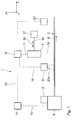
- the apparatus 1 has an extruder 4 for extruding the article 2.
- the extruder 4 For applying a coating 5 (see Fig. 3) to be described by coextrusion, the extruder 4 has a schematically indicated coating device 6.
- FIGS. 1 and 2 a Cartesian xyz coordinate system is shown in FIGS. 1 and 2.
- the x-direction extends to the right, the y-direction perpendicular to the plane of the drawing, and the z-direction to the top. The same applies to FIG. 2.
- the laser marking device 7 is connected to a tracking device 17.
- the mechanical connection 16 is a linear guide. With the entrainment device 17, a displacement of the laser marking device 7 along the x-direction is possible, as indicated by a double arrow 18.
- the marking control device 12 is in signal connection with a detection device 20.
- the latter has a line camera 20a whose line extends parallel to the y-direction and which detects a section of the object surface 8 to be marked.
- a digital camera, an area camera or another type of sensor can also be used.
- the laser beam source 21 used is an Nd: YAG laser. It is a pulsed laser with a pulse frequency of 20 kHz.
- the laser wavelength is 1064 nm.
- the laser has an average power of 50 W.
- the individual laser pulses have a pulse duration of about 130 ns.
- the single pulse energy is about 2.1 mJ.
- the laser can also be operated with a pulse frequency of 10 kHz.
- the individual pulses then have a duration of about 100 ns and an energy of about 4mJ.
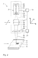
- the resonator of the laser beam source 21 has a highly reflective first resonator mirror 22 shown in FIG. 2 above and, forming the other end of the resonator, a partially reflecting second resonator mirror 23.
- the laser radiation 10 generated by the laser beam source 21 initially passes after exiting the resonator a deflection device 26. With the aid of this, the laser radiation 10 in two mutually perpendicular deflection directions, namely in the x and y directions, perpendicular to the beam direction of the laser radiation 10 are distracted.
- the laser marking device 7 is translationally displaceable in the x-, y- and z-direction by means of a drive, not shown, wherein in rotationally symmetrical components, a displacement advantageously takes place in polar coordinates.
- a signal line 30 indicated by dashed lines the laser marking device 7 is in signal connection with a focal position control device 31.
- the focal position control device 31 in turn is connected to the marking control device 12 via a signal line 32, and the marking control device 12 is connected via a signal line 33 to the deflection device 26 and via a signal line 34 to the laser beam source 21 in signal connection.
- the signal lines 32 to 34 are sub-lines of the signal line 11.
- the coating device 6 already mentioned above serves to apply the coating 5 which is color-shift-sensitive to the laser radiation 10 on the object surface 8 to be marked. This is described by way of example of a gas pipe as object 2, which is shown in cross-section in FIG.
- the coating device 6 generates by coextrusion a total of five longitudinal strips 35, which together form the coating 5.
- the longitudinal strips 35 are extruded on the outer circumference of the gas pipe 2 and are equally distributed in the circumferential direction, that is offset by 72 ° to each other.
- the individual longitudinal strips 35 are greatly exaggerated in their thickness in FIG. In fact, each longitudinal strip 35 has a layer thickness of about 0.15 mm.
- the longitudinal strips 35 are also made of a PE-containing base material, which in contrast to the other gas tube 2 TiO 2 -containing.
- the width of each longitudinal strip 35 is at least as large as the width of the marking field 9.
- the article 2 having the cross section of FIG. 3 is extruded.
- the detection device 20 detects with the line camera 20a the position of the laser marking device 7 next facing longitudinal strip 35.
- the line camera 20a detects the border areas between the present in the detection area longitudinal strip 35 and surrounding this other object 2. This color difference results from the fact that the Longitudinal stripes 35 z.
- Fig. 3 is shown in cross-section of the gas pipe 2 at the top of the longitudinal strips 35 drawn through in the ideal position for marking. Dashed in the circumferential direction by 36 ° clockwise an alternative position of the longitudinal strip 35 is shown.
- the information mark 3 is applied to the longitudinal strips 35.
- the x-feed takes place during marking by superposition of the extrusion feed with the x feed of the laser marking device 7.
- the latter can be generated by an x-feed of the deflection device 26 and / or by carrying the laser marking device 7 with the object 2 by means of the entrainment device 17 ,
- the article 2 with the information mark 3, without providing the coating 5.
- This increases the demands placed on the laser marking device 7.
- the detection device 20 is omitted in the case of the device 1, and accordingly a calibration of the laser marking device 7 is omitted, which concerns the values ⁇ y and ⁇ F.
- an unevenness of the object surface 8 the z. B. can be caused by an ovality of a tubular tube or even by other unevenness of an article surface, a .DELTA.F correction may still require.
- a device 20 'comparable to the detection device 20 can monitor the quality of the applied information mark 3 by optically scanning it.
- Such a device 20 ' is shown in FIG. 1 by dashed lines over the object 2, which has already passed the laser marking device 7.
- the device 20 'can also serve for quality control and for the control or regulation of the laser marking device 7.
- laser marking devices 7 can be used, for.
- the coating 5 may be colored and in particular have a similar color as the other object color.
- the coating 5 by printing, by gluing, z. B. in the form of a film, or by welding. It is also possible to provide the article surface 8 to be marked completely with the coating 5. This can be z. B. done in the form of a vacuum jacket. For this purpose, the z. B. in the form of a tube coating applied by vacuum on the object 2.
- the PE material is highly transparent to the laser radiation 10, so that more than 90% of the laser radiation 10 is not absorbed by the article material. Thus, a self-limitation of the laser effects on the thickness of the coating 5 is achieved.
- the pigment doping provides for the marking contrast.
- the residual interaction of the article material with the high-intensity laser radiation 10 is sufficient to produce a sufficient marking contrast.
Landscapes
- Physics & Mathematics (AREA)
- Optics & Photonics (AREA)
- Engineering & Computer Science (AREA)
- Mechanical Engineering (AREA)
- Health & Medical Sciences (AREA)
- General Health & Medical Sciences (AREA)
- Toxicology (AREA)
- Thermal Transfer Or Thermal Recording In General (AREA)
- Laser Beam Processing (AREA)
- Extrusion Moulding Of Plastics Or The Like (AREA)
Abstract
Description
- Die Erfindung betrifft ein Verfahren sowie eine Vorrichtung zur Herstellung eines Polyethylen-(PE)-Gegenstands mit einer maschinenlesbar codierten Informationsmarkierung.
- Ein derartiges Verfahren sowie eine Vorrichtung hierzu sind durch offenkundige Vorbenutzung bekannt. Hierbei werden auf den Gegenstand Etikettenaufkleber aufgebracht, die die Informationsmarkierung oder -signierung tragen. Dieses Verfahren hat als Hauptnachteil die geringe Haltbarkeit der Etiketten auf dem Rohr. Ein weiterer Nachteil ist, dass auch die Signierung selbst auf den Etiketten oftmals nicht ausreichend haftet.
- Es ist daher eine Aufgabe der vorliegenden Erfindung, ein Verfahren der eingangs genannten Art sowie eine Vorrichtung hierfür derart weiterzubilden, dass ein dauerhaftes und möglichst unaufwändiges Aufbringen der Informationsmarkierung auf den Gegenstand gewährleistet ist.
- Diese Aufgabe ist, was das Verfahren angeht, erfindungsgemäß gelöst durch ein Verfahren mit den im Anspruch 1 angegebenen Merkmalen.
- Überraschend hat sich herausgestellt, dass auch PE-Gegenstände einer Lasermarkierung zugänglich sind. Dies war bisher nicht in Betracht gezogen worden, da PE für die Wellenlängen der typischen Markierlaser, die insbesondere im Bereich von 1 µm liegen, im Wesentlichen transparent ist. Es findet daher im Polyethylen kaum eine Wechselwirkung des Materials mit der Laserstrahlung statt, so dass nicht zu erwarten war, dass eine Lasermarkierung bzw. -signierung von Polyethylen möglich ist. Erfindungsgemäß wurde erkannt, dass eine Lasermarkierung von Polyethylen möglich ist, wenn eine Laserstrahlquelle sehr hoher mittlerer Leistung eingesetzt wird. Eine Laserstrahlquelle mit einer mittleren Leistung von mindestens 10 W, insbesondere mit einer mittleren Leistung von mehr als 50 W hat sich als für das Markieren von Polyethylen geeignet herausgestellt.
- Dadurch, dass als Markiervorschub zumindest teilweise der Extrusionsvorschub genutzt wird, kann das Markieren des Gegenstands effizient in den Herstellprozess des Gegenstandes integriert werden. Neben der codierten Informationsmarkierung kann online auch Klartext mittels Lasermarkieren aufgebracht werden. Die Informationsmarkierung, bei der es sich z. B. um einen Barcode oder um einen zweidimensionalen Data-Matrix-Code handeln kann, lässt sich sehr gut haltbar auf den Gegenstand aufbringen. Ein Wechsel der Art der aufgebrachten Informationsmarkierung ist durch entsprechendes Ändern der Markier-Ansteuerdaten einfach möglich.
- Eine Vorschubüberlagerung nach den Ansprüchen 2 bis 4 schafft die Möglichkeit, Schwankungen im Extrusionsvorschub auszugleichen. Der Ablenkvorschub kann insbesondere so viel schneller sein als der Extrusionsvorschub, dass es auf Schwankungen im Extrusionsvorschub überhaupt nicht mehr ankommt. Der Extrusionsvorschub wird dann hauptsächlich dazu genutzt, Abstände zwischen den längs des Gegenstands aufgebrachten Informationsmarkierungen zu schaffen. Je nach den Anforderungen an den Laseraufbau und an die Bündelführung hat sich das Erzeugen des Ablenkvorschubs durch einen Ablenkspiegel und/oder eine Bündelformungslinse als vorteilhaft herausgestellt.
- Eine Vorschubüberlagerung nach Anspruch 5 ermöglicht auch das Aufbringen von Informationsmarkierungen, bei denen das Markieren auf kleinem Raum relativ viel Zeit erfordert. Eine Beschichtung nach Anspruch 6 verringert die Anforderungen, die an die Leistungsfähigkeit der Laserstrahlquelle zur Erzeugung der Markierung auf dem Polyethylen-Gegenstand gestellt werden. Die Informationsmarkierung wird auf der Beschichtung erzeugt, wo die Laserstrahlung für einen definierten Farbumschlag sorgt. Da die Beschichtung sensitiv auf die Laserstrahlung mit einem Farbumschlag reagiert, ist nur ein geringer Energiebedarf beim Laser erforderlich. Zudem sind hohe Markiergeschwindigkeiten realisierbar. Die Beschichtung kann insbesondere so ausgelegt sein, dass sie eine hohe Absorption für die Wellenlänge der Laserstrahlung hat. Es resultiert eine geringe Eindringtiefe der Laserstrahlung in der Beschichtung, so dass das Gegenstandsmaterial unter der Beschichtung von Laserstrahlung praktisch nicht durchdrungen wird, so dass eine Schädigung des sonstigen Gegenstandsmaterials durch die Laserstrahlung ausgeschlossen ist. Die hohe Farbumschlagssensitivität ermöglicht die Erzeugung von Markierungen mit hohem Kontrast. Die Markierung ist daher sowohl für ein Benutzerauge als auch für eine Lesemaschine, z. B. einen Scanner, gut lesbar.
- Da wenig Energie in die Beschichtung eingetragen werden muss, um den Farbumschlag zu erzeugen, kann die von der Laserstrahlung beaufschlagte Oberfläche der Beschichtung glatt bleiben.
- Beschichtungs-Längsstreifen nach Anspruch 7 können so ausgestaltet sein, dass ihr relativer Anteil am Volumen des gesamten Gegenstands vernachlässigbar gering ist. Derartige Beschichtungen können auch dort eingesetzt werden, wo es sensibel auf die Materialzusammensetzung des Gegenstands ankommt, z. B. bei Gasrohren, Trinkwasserrohren, Druckentwässerungen oder bei Fernwärmeleitungen. Alternativ kann auch eine die zu markierende Gegenstandsoberfläche vollständig abdeckende Beschichtung eingesetzt werden. Die Beschichtungs-Längsstreifen eignen sich zudem gut als optische Produktkennzeichnung. Die Längsstreifen können dabei so auf den Gegenstand aufgebracht sein, dass mindestens ein Längsstreifen sichtbar ist, unabhängig davon, aus welcher Richtung der Gegenstand betrachtet wird.
- Eine Erfassung nach Anspruch 8 erleichtert das Markieren bei Einsatz einer Längsstreifen-Beschichtung, da auf ein spezielles Ausrichten des Rohrs zum Laser verzichtet werden kann. Es wird vielmehr der Laser zum Rohr ausgerichtet.
- Eine Fokalebenen-Nachstellung nach Anspruch 9 gewährleistet eine definierte Bündelung der Laserstrahlung auf die zu markierende Gegenstandsobenfläche.
- Die eingangs genannte Aufgabe ist, was die Vorrichtung angeht, gelöst durch eine Herstellungsvorrichtung mit den im Anspruch 10 angegebenen Merkmalen.
- Die Vorteile der Herstellungsvorrichtung entsprechen denen, die vorstehend im Zusammenhang mit dem Herstellungsverfahren schon diskutiert wurden.
- Eine Zeilenkamera nach Anspruch 17 gewährleistet eine sichere und hochgenaue Erfassung des Beschichtungs-Längsstreifens. Alternativ kann auch eine Digitalkamera, eine Flächenkamera oder ein anderer Typ eines Sensors zum Einsatz kommen.
- Ein Ausführungsbeispiel der Erfindung wird nachfolgend anhand der Zeichnung näher erläutert. In dieser zeigen:
- Fig. 1
- schematisch eine Vorrichtung zur Herstellung eines Polyethylen-Gegenstands mit einer maschinenlesbar markierten Informationsmarkierung;
- Fig. 2
- schematisch aber stärker im Detail eine Laserstrahlmarkiereinrichtung der Herstellungsvorrichtung nach Fig. 1 beim Markieren des Gegenstands; und
- Fig. 3
- einen Querschnitt durch einen alternativen Gegenstand mit einer farbumschlagssensitiven Beschichtung in Form mehrerer Längsstreifen.
- Eine Vorrichtung 1 zur Herstellung eines Polyethylen-(PE)-Gegenstands 2 mit einer maschinenlesbar codierten Informationsmarkierung 3 ist schematisch mit ihren Hauptkomponenten in der Fig. 1 dargestellt. Ein Beispiel für die Informationsmarkierung 3, nämlich einen Barcode, zeigt die Fig. 2, auf die später noch eingegangen wird. Alternativ zu einem Barcode sind auch andere maschinenlesbar codierte Informationsmarkierungen mit der Vorrichtung 1 herstellbar, z. B. ein zweidimensionaler Data-Matrix-Code.
- Bei dem Gegenstand 2 handelt es sich um ein Gasrohr aus dem Material PE 80. Auch andere Gegenstände 2 sind möglich, beispielsweise die Materialien PE 100 oder PE-X, insbesondere PE-Xa, d. h. peroxidisch vernetztes PE. Es können auch Gegenstände für andere Anwendungen hergestellt werden, z. B. Trinkwasserrohre, Rohre zur Druckentwässerung oder Fernwärmerohre. Auch die Herstellung von nicht rohrförmigen Gegenständen 2, z. B. von Platten, ist möglich.
- Der Barcode 3 trägt als Informationsinhalt den Hersteller des Gegenstandes 2, das Material des Gegenstandes 2, die Norm oder die Normen, die vom Gegenstand 2 erfüllt werden, Dimensionsdaten zum Gegenstand 2, Produktionsdaten zum Gegenstand 2, insbesondere Daten, welche Rückschlüsse auf die individuelle Herstellungsvorrichtung 1 zulassen, sowie das Produktionsdatum und den laufenden Produktionsmeter des Gegenstands 2.
- Die Vorrichtung 1 hat einen Extruder 4 zum Extrudieren des Gegenstands 2. Zum Aufbringen einer noch zu beschreibenden Beschichtung 5 (vgl. Fig. 3) durch Koextrusion hat der Extruder 4 eine schematisch angedeutete Beschichtungseinrichtung 6.
- Zur Erzeugung der Informationsmarkierung 3 auf dem Gegenstand 2 hat die Vorrichtung 1 eine Lasermarkiervorrichtung 7. Letztere beaufschlagt eine zu markierende Gegenstandsoberfläche 8 innerhalb eines Markierfeldes 9 (vgl. Fig. 2) mit gebündelter Laserstrahlung 10. Das Markierfeld 9 hat eine Breite im Bereich einiger 10 mm. Über eine Signalleitung 11 steht die Lasermarkiervorrichtung 7 mit einer Markiersteuereinrichtung 12 in Signalverbindung. Über eine Signalleitung 13 steht die Markiersteuereinrichtung 12 mit einer Extruder-Steuereinrichtung 14 in Verbindung, die wiederum über eine Signalleitung 15 mit dem Extruder 4 verbunden ist.
- Zur Verständniserleichterung ist in den Fig. 1 und 2 ein kartesisches xyz-Koordinatensystem eingezeichnet. In der Fig. 1 verläuft die x-Richtung nach rechts, die y-Richtung senkrecht in die Zeichenebene hinein und die z-Richtung nach oben. Entsprechendes gilt für die Fig. 2.
- Über eine in der Fig. 1 angedeutete mechanische Verbindung 16 steht die Lasermarkiervorrichtung 7 mit einer Mitführeinrichtung 17 in Verbindung. Bei der mechanischen Verbindung 16 handelt es sich um eine Linearführung. Mit der Mitführeinrichtung 17 ist eine Verlagerung der Lasermarkiervorrichtung 7 längs der x-Richtung möglich, wie durch einen Doppelpfeil 18 angedeutet.
- Über eine weitere Signalleitung 19 steht die Markiersteuereinrichtung 12 mit einer Erfassungseinrichtung 20 in Signalverbindung. Letztere weist eine Zeilenkamera 20a auf, deren Zeile sich parallel zur y-Richtung erstreckt und die einen Ausschnitt der zu markierenden Gegenstandsoberfläche 8 erfasst. Alternativ zur Zeilenkamera 20a kann auch eine Digitalkamera, eine Flächenkamera oder ein anderer Typ eines Sensors eingesetzt sein.
- Details der Lasermarkiervorrichtung 7 zeigt Fig. 2. Als Laserstrahlquelle 21 dient ein Nd:YAG-Laser. Es handelt sich um einen gepulsten Laser mit einer Pulsfrequenz von 20 kHz. Die Laserwellenlänge beträgt 1064 nm. Der Laser hat eine mittlere Leistung von 50 W. Die einzelnen Laserpulse haben eine Pulsdauer von ca. 130 ns. Die Einzelimpulsenergie beträgt etwa 2,1 mJ. Alternativ kann der Laser auch mit einer Pulsfrequenz von 10 kHz betrieben werden. Die Einzelimpulse haben dann eine Dauer von ca. 100 ns und eine Energie von etwa 4mJ. Der Resonator der Laserstrahlquelle 21 hat einen in der Fig. 2 oben dargestellten hochreflektierenden ersten Resonatorspiegel 22 und, das andere Ende des Resonators bildend, einen teilreflektierenden zweiten Resonatorspiegel 23.
- Zwischen den Resonatorspiegeln 22, 23 ist ein Nd:YAG-Lasermedium 24 angeordnet. Zwischen dem Lasermedium 24 und dem ersten Resonatorspiegel 22 ist noch ein Pulsmodulator 25 angedeutet.
- Die von der Laserstrahlquelle 21 erzeugte Laserstrahlung 10 passiert nach dem Austreten aus dem Resonator zunächst eine Ablenkeinrichtung 26. Mit Hilfe von dieser kann die Laserstrahlung 10 in zwei zueinander senkrechten Ablenkrichtungen, nämlich in x- und y-Richtung, die senkrecht auf der Strahlrichtung der Laserstrahlung 10 liegen, abgelenkt werden.
- Die Vorschubgeschwindigkeit des Gegenstands 2, also des Extrudats, in x-Richtung beträgt einige m/min.
- Die Ablenkeinrichtung 26 hat zwei in der Fig. 2 schematisch dargestellte Ablenkspiegel 27, 28, die als um zueinander senkrechte Achsen galvanisch verkippbare Spiegel gebildet sind. Der erste Ablenkspiegel 27 dient beispielsweise der x-Ablenkung und der zweite Ablenkspiegel 28 der y-Ablenkung der Laserstrahlung 10.
- Nach Durchtreten der Ablenkeinrichtung 26 durchtritt die Laserstrahlung 10 eine Bündelformungseinrichtung 29, z. B. eine Plankonvexlinse.
- Die Lasermarkiervorrichtung 7 ist mit Hilfe eines nicht dargestellten Antriebs translatorisch in x-, y- und z-Richtung verlagerbar, wobei bei rotationssymmetrischen Bauteilen eine Verlagerung vorteilhafterweise in polaren Koordinaten erfolgt. Über eine gestrichelt angedeutete Signalleitung 30 steht die Lasermarkiervorrichtung 7 mit einer Fokalpositions-Regeleinrichtung 31 in Signalverbindung. Die Fokalpositions-Regeleinrichtung 31 wiederum steht über eine Signalleitung 32 mit der Markiersteuereinrichtung 12 und die Markiersteuereinrichtung 12 steht über eine Signalleitung 33 mit der Ablenkeinrichtung 26 und über eine Signalleitung 34 mit der Laserstrahlquelle 21 in Signalverbindung. Die Signalleitungen 32 bis 34 sind Teilleitungen der Signalleitung 11.
- Die oben schon erwähnte Beschichtungseinrichtung 6 dient zum Aufbringen der für die Laserstrahlung 10 farbumschlagssensitiven Beschichtung 5 auf der zu markierenden Gegenstandsoberfläche 8. Dies ist am Beispiel eines Gasrohrs als Gegenstand 2 beschrieben, welches in der Fig. 3 im Querschnitt dargestellt ist.
- Die Beschichtungseinrichtung 6 erzeugt mittels Koextrusion insgesamt fünf Längsstreifen 35, die zusammen die Beschichtung 5 ergeben. Die Längsstreifen 35 sind am äußeren Umfang des Gasrohrs 2 anextrudiert und liegen in Umfangsrichtung gleich verteilt vor, sind also um jeweils 72° zueinander versetzt. Die einzelnen Längsstreifen 35 sind in ihrer Dicke in der Fig. 3 stark übertrieben dargestellt. Tatsächlich hat jeder Längsstreifen 35 eine Schichtdicke von etwa 0,15 mm. Die Längsstreifen 35 sind ebenfalls aus einem PE-haltigen Grundmaterial, welches im Unterschied zum sonstigen Gasrohr 2 TiO2-haltig ist. Die Breite jedes Längsstreifens 35 ist mindestens so groß wie die Breite des Markierfelds 9.
- Nachfolgend wird ein Verfahren zum Herstellen des die Informationsmarkierung 3 aufweisenden Gegenstands 2 beschrieben: Zunächst wird mit dem Extruder 4 der Gegenstand 2 mit dem Querschnitt nach Fig. 3 extrudiert. Die Erfassungseinrichtung 20 erfasst dann mit der Zeilenkamera 20a die Lage des der Lasermarkiervorrichtung 7 nächst zugewandten Längsstreifens 35. Hierzu erfasst die Zeilenkamera 20a die Grenzbereiche zwischen dem im Erfassungsbereich vorliegenden Längsstreifen 35 und dem diesen umgebenden sonstigen Gegenstand 2. Dieser Farbunterschied ergibt sich dadurch, dass die Längsstreifen 35 z. B. etwas heller ausgeführt sind als das sonstige Gasrohr 2. In der Fig. 3 ist im Querschnitt des Gasrohrs 2 ganz oben der Längsstreifen 35 durchgezogen in der Idealposition zum Markieren dargestellt. In Umfangsrichtung um 36° im Uhrzeigersinn versetzt gestrichelt ist eine alternative Lage des Längsstreifens 35 dargestellt. Die Erfassungseinrichtung 20 erfasst die y-Abweichung Δy des Längsstreifens 35, mit der eine z-Abweichung ΔF einhergeht. Beide Werte Δy und ΔF gibt die Erfassungseinrichtung 20 an die Markiersteuereinrichtung 12 weiter. Entsprechend der y-Abweichung wird die Ablenkeinrichtung 26 und/oder die Lasermarkiervorrichtung 7 voreingestellt, so dass die Laserstrahlung 10 auf den Längsstreifen 35 in der von der Erfassungseinrichtung 20 erfassten Position trifft. Auch die Lage der durch die Bündelformungseinrichtung 29 erzeugten Fokalebene wird, insbesondere durch z-Verlagerung der Lasermarkiervorrichtung 7 entsprechend dem Wert ΔF eingestellt. Eine weitere ΔF-Korrektur kann sich z. B. durch eine Ovalität der Querschnittsgeometrie des Gasrohrs 2 ergeben. Die ΔF-Korrektur wird durchgeführt, indem die Markiersteuereinrichtung 12 entsprechend die Fokalpositions-Regeleinrichtung 31 mit Informationen versorgt.
- Nach der Lageerfassung des Längsstrahls 35 und einer entsprechenden Kalibrierung der Lasermarkiervorrichtung 7 wird auf den Längsstreifen 35 die Informationsmarkierung 3 aufgebracht.
- Hierzu rastert die Laserstrahlung 10 das Markierfeld 9 mit einer voreingestellten Rasterbreite sowie mit einem voreingestellten Rasterabstand ab. Die Rasterbreite kann z. B. der Breite des Längsstreifens 35 entsprechen. Der Rasterabstand, also der Abstand zweier Zeilen des Rasters sowie der Abstand zweier Punkte innerhalb einer Rasterzeile beträgt 0,1 bis 0,2 mm. Auch kleine Zeilenabstände, z. B. 80 µm, sind möglich. Auch kleine Punktabstände innerhalb einer Zeile, z. B. 20 µm, sind möglich. Die Laserstrahlung 10 wird auf dem Gegenstand 2 mit einer Ablenkgeschwindigkeit von 2.600 mm/sec mittels der Ablenkeinrichtung 26 abgelenkt. Beim Auftreffen der Laserstrahlung 10 auf den TiO2-dotierten Längsstreifen 35 erfolgt ein Farbumschlag, z. B. eine Schwärzung des Materials des Längsstreifens 35 dort, wo die Laserstrahlung aufgetroffen ist. Auf diese Weise entsteht die Markierung 3, z. B. ein Barcode, mit hohem Kontrast. Der x-Vorschub geschieht beim Markieren durch eine Überlagerung des Extrusionsvorschubs mit dem x-Vorschub der Lasermarkiervorrichtung 7. Letztere kann erzeugt werden durch einen x-Vorschub der Ablenkeinrichtung 26 und/oder durch Mitführen der Lasermarkiervorrichtung 7 mit dem Gegenstand 2 mit Hilfe der Mitführeinrichtung 17.
- Prinzipiell ist es auch möglich, den Gegenstand 2 mit der Informationsmarkierung 3 zu versehen, ohne die Beschichtung 5 vorzusehen. Dies erhöht die Anforderungen, die an die Lasermarkiervorrichtung 7 gestellt werden. Soweit keine Beschichtung 5 erforderlich ist, entfällt bei der Vorrichtung 1 die Erfassungseinrichtung 20 und entsprechend entfällt eine Kalibrierung der Lasermarkiervorrichtung 7, was die Werte Δy und ΔF angeht. Allenfalls eine Unebenheit der Gegenstandsoberfläche 8, die z. B. durch eine Ovalität eines rohrförmigen Rohres oder aber auch durch andere Unebenheiten einer Gegenstandsoberfläche hervorgerufen werden kann, kann eine ΔF-Korrektur noch erfordern.
- Eine der Erfassungseinrichtung 20 vergleichbare Einrichtung 20' kann die Qualität der aufgebrachten Informationsmarkierung 3 durch optisches Abtasten von dieser überwachen. Eine derartige Einrichtung 20' ist in der Fig. 1 gestrichelt über dem Gegenstand 2, welches die Lasermarkiervorrichtung 7 bereits passiert hat, angeordnet. Neben der Überwachung kann die Einrichtung 20' auch der Qualitätskontrolle sowie der Steuerung bzw. Regelung der Lasermarkiervorrichtung 7 dienen.
- Auch andere Lasermarkiervorrichtungen 7 können zum Einsatz kommen, z. B. ein Faserlaser mit einer Leistung > 10 W, vorzugsweise > 50 W.
- Anstelle von TiO2 können auch andere laseraktive Pigmente zudotiert werden. Die Beschichtung 5 kann eingefärbt sein und insbesondere eine ähnliche Farbe aufweisen wie die sonstige Gegenstandsfarbe.
- Anstelle durch Koextrusion kann die Beschichtung 5 auch durch Aufdrucken, durch Aufkleben, z. B. in Form einer Folie, oder durch Aufschweißen erfolgen. Es ist auch möglich, die zu markierende Gegenstandsoberfläche 8 vollständig mit der Beschichtung 5 zu versehen. Dies kann z. B. in Form einer Vakuumummantelung geschehen. Hierzu wird die z. B. in Form eines Schlauchs vorliegende Beschichtung durch Vakuum auf den Gegenstand 2 aufgezogen.
- Mit dieser Vorrichtung ist es auch möglich die Informationsmarkierung 3 durch Abtragen von Teilbereichen der Beschichtung 5 des Gegenstands 2 herzustellen. Diese Ausführung ist besonders vorteilhaft, wenn der Kontrast zwischen Gegenstand 2 und Beschichtung 5 für eine Lesbarkeit ausreicht.
- Das PE-Material ist für die Laserstrahlung 10 hochtransparent, so dass mehr als 90% der Laserstrahlung 10 nicht vom Gegenstandsmaterial absorbiert werden. Somit wird eine Selbstbegrenzung der Lasereffekte auf die Dicke der Beschichtung 5 erreicht. Im Falle des die Beschichtung 5 aufweisenden Gegenstands 2 sorgt die Pigmentdotierung für den Markierkontrast. Bei unbeschichteten Gegenständen 2 genügt die Rest-Wechselwirkung des Gegenstandsmaterials mit der hochintensiven Laserstrahlung 10, um einen ausreichenden Markierkontrast zu erzeugen.
Claims (16)
- Verfahren zur Herstellung eines Polyethylen-(PE)-Gegenstands (2) mit einer maschinenlesbar codierten Informationsmarkierung (3) mit folgenden Verfahrensschritten:- Extrudieren des Gegenstands (2),- Aufbringen der Markierung (3) durch Beaufschlagen eines Markierfeldes (9) auf der zu markierenden Gegenstandsoberfläche (8) mit gebündelter Laserstrahlung (10) einer Laserstrahlquelle (21) hoher Leistung und einer Wellenlänge, für die der Gegenstand eine hohe Transparenz hat,- wobei ein Markiervorschub längs des Gegenstands (2) zumindest teilweise durch einen Extrusionsvorschub erfolgt.
- Verfahren nach Anspruch 1, gekennzeichnet durch ein Ablenken der Laserstrahlung (10) zum Führen innerhalb des Markierfeldes (9) auf der Gegenstandsoberfläche (8) während des Markierens, wobei ein Ablenkvorschub längs des Gegenstands (2) dem Extrusionsvorschub überlagert wird.
- Verfahren nach Anspruch 2, dadurch gekennzeichnet, dass die Vorschubüberlagerung durch Verlagern mindestens eines Ablenkspiegels (27, 28) für die Laserstrahlung (10) erfolgt.
- Verfahren nach Anspruch 2 oder 3, dadurch gekennzeichnet, dass die Vorschubüberlagerung durch Verlagern der Lasermarkiervorrichtung (7) erfolgt.
- Verfahren nach einem der Ansprüche 1 bis 4, gekennzeichnet durch ein Aufbringen einer für die Laserstrahlung (10) farbumschlagssensitiven, insbesondere pigmenthaltigen, vorzugsweise TiO2-haltigen Beschichtung (5) auf der zu markierenden Gegenstandsoberfläche (8).
- Verfahren nach Anspruch 5, dadurch gekennzeichnet, dass die Beschichtung (5) in Form mindestens eines Längsstreifens (35) auf die zu markierende Gegenstandsoberfläche (8) aufgebracht wird, dessen Breite mindestens so groß ist wie die Breite des Markierfeldes (9).
- Verfahren nach Anspruch 6 zum Aufbringen der Informationsmarkierung (3) auf ein Rohr als Gegenstand (2), dadurch gekennzeichnet, dass die Umfangsposition des mindestens einen Längsstreifens (35) sensorisch erfasst wird und anhand der Informationen der sensorischen Erfassung ein Nachführen der Laserstrahlung (10) erfolgt.
- Verfahren nach einem der Ansprüche 1 bis 7, dadurch gekennzeichnet, dass abhängig vom Abstand der Laserstrahlquelle (21) zum Markierfeld (9) und/oder abhängig von der Umfangs-Nachführung der Laserstrahlung (10) die Lage der Fokalebene der Laserstrahlung (10) relativ zur Lage des Markierfeldes (9) nachgestellt wird.
- Vorrichtung (1) zur Herstellung eines Polyethylen-(PE)-Gegenstands (2) mit einer maschinenlesbar codierten Informationsmarkierung (3) mit- einem Extruder (4) zum Extrudieren des Gegenstands (2),- einer Laserstrahlquelle (21) zum Aufbringen der Markierung (3) durch Beaufschlagen eines Markierfeldes (9) auf der zu markierenden Gegenstandsoberfläche (8) mit gebündelter Laserstrahlung (10) hoher Leistung und einer Wellenlänge, für die der Gegenstand (2) eine hohe Transparenz hat,- wobei eine Markiersteuereinrichtung (12) mit einer Extruder-Steuereinrichtung (14) derart zusammenwirkt, dass ein Markiervorschub längs des Gegenstands (2) zumindest teilweise durch einen Extrusionsvorschub erfolgt.
- Vorrichtung nach Anspruch 9, gekennzeichnet durch eine Ablenkeinrichtung (26; 29) zum Ablenken der Laserstrahlung (10) zum Führen innerhalb des Markierfeldes (9) auf der Gegenstandsoberfläche (8) während des Markierens, wobei ein Ablenkvorschub längs des Gegenstands (2) dem Extrusionsvorschub überlagert wird.
- Vorrichtung nach Anspruch 10, gekennzeichnet durch mindestens einen gesteuert verlagerbaren Ablenkspiegel (27, 28) für die Laserstrahlung (10) als Teil der Ablenkeinrichtung (26, 29).
- Vorrichtung nach einem der Ansprüche 9 bis 11, gekennzeichnet durch eine Mitführeinrichtung (17) zum Mitführen der Lasermarkiervorrichtung (7) mit dem Gegenstand (2).
- Vorrichtung nach einem der Ansprüche 9 bis 12, gekennzeichnet durch eine Beschichtungseinrichtung (6) zum Aufbringen einer für die Laserstrahlung (10) farbumschlagssensitiven Beschichtung (5) auf der zu markierenden Gegenstandsoberfläche (8), insbesondere in Form mindestens eines Längsstreifens (35), dessen Breite mindestens so groß ist wie die Breite des Markierfeldes (9).
- Vorrichtung nach einem der Ansprüche 9 bis 13, dadurch gekennzeichnet, dass der Extruder (4) zum Extrudieren eines Rohrs als Gegenstand (2) und die Beschichtungseinrichtung (6) zum Aufbringen der Längsstreifen (35) ausgebildet sind, wobei eine Erfassungseinrichtung (20) vorgesehen ist, die die Umfangsposition des mindestens einen Längsstreifens (35) sensorisch erfasst und derart ausgebildet ist, dass sie diese Information an die Markiersteuereinrichtung (12) zum Nachführen der Laserstrahlung (10) weitergibt.
- Vorrichtung nach Anspruch 14, dadurch gekennzeichnet, dass die Erfassungseinrichtung (20) eine Zeilenkamera (20a) aufweist.
- Vorrichtung nach einem der Ansprüche 9 bis 15, gekennzeichnet durch eine Fokalpositions-Regeleinrichtung (31), welche abhängig vom Abstand der Laserstrahlquelle (21) zum Markierfeld (9) und/oder abhängig von der Umfangs-Nachführung der Laserstrahlung (10) die Lage einer Fokalebene der Laserstrahlung (10) relativ zur Lage des Markierfeldes (9) nachfährt.
Priority Applications (2)
| Application Number | Priority Date | Filing Date | Title |
|---|---|---|---|
| PL07010434T PL1897699T3 (pl) | 2006-06-07 | 2007-05-25 | Sposób oraz urządzenie do wytwarzania przedmiotu polietylenowego z oznakowaniem informacyjnym zakodowanym do odczytu maszynowego |
| SI200731490T SI1897699T1 (sl) | 2006-06-07 | 2007-05-25 | Postopek in naprava za izdelavo polietilenskega predmeta s kodirano podatkovno oznako, ki je strojno berljiva |
Applications Claiming Priority (1)
| Application Number | Priority Date | Filing Date | Title |
|---|---|---|---|
| DE102006026790A DE102006026790A1 (de) | 2006-06-07 | 2006-06-07 | Verfahren sowie Vorrichtung zur Herstellung eines Polyethylen-Gegenstands mit einer maschinenlesbar codierten Informationsmarkierung |
Publications (3)
| Publication Number | Publication Date |
|---|---|
| EP1897699A2 true EP1897699A2 (de) | 2008-03-12 |
| EP1897699A3 EP1897699A3 (de) | 2011-06-01 |
| EP1897699B1 EP1897699B1 (de) | 2014-04-30 |
Family
ID=38663745
Family Applications (1)
| Application Number | Title | Priority Date | Filing Date |
|---|---|---|---|
| EP07010434.4A Not-in-force EP1897699B1 (de) | 2006-06-07 | 2007-05-25 | Verfahren sowie Vorrichtung zur Herstellung eines Polyethylen-Gegenstands mit einer maschinenlesbar codierten Informationsmarkierung |
Country Status (5)
| Country | Link |
|---|---|
| EP (1) | EP1897699B1 (de) |
| DE (1) | DE102006026790A1 (de) |
| DK (1) | DK1897699T3 (de) |
| PL (1) | PL1897699T3 (de) |
| SI (1) | SI1897699T1 (de) |
Cited By (1)
| Publication number | Priority date | Publication date | Assignee | Title |
|---|---|---|---|---|
| DE202011050031U1 (de) | 2011-05-04 | 2011-07-28 | Dipl.-Ing. Dr. Ernst Vogelsang Gmbh & Co Kg | Kabelführungsrohr |
Families Citing this family (4)
| Publication number | Priority date | Publication date | Assignee | Title |
|---|---|---|---|---|
| DE102007024546A1 (de) * | 2007-05-24 | 2008-11-27 | Nwl Lasertechnologie Gmbh | Verfahren zum Kennzeichnen extrudierter Kunststoffprofile |
| DE102008006276A1 (de) * | 2008-01-25 | 2009-07-30 | Gerhardt Friedel | Verfahren zur Herstellung eines porösen Schlauchs |
| US20090266804A1 (en) * | 2008-04-24 | 2009-10-29 | Costin Darryl J | Combination extrusion and laser-marking system, and related method |
| DE102023125108A1 (de) * | 2023-09-18 | 2025-03-20 | Khs Gmbh | Vorrichtung und Verfahren zum Markieren von Verpackungen |
Citations (1)
| Publication number | Priority date | Publication date | Assignee | Title |
|---|---|---|---|---|
| EP0415674A2 (de) | 1989-09-01 | 1991-03-06 | AT&T Corp. | Markierter Gegenstand und Verfahren zu seiner Herstellung |
Family Cites Families (7)
| Publication number | Priority date | Publication date | Assignee | Title |
|---|---|---|---|---|
| EP0710570A1 (de) * | 1994-11-04 | 1996-05-08 | Quantum Chemical Corporation | Polymerzusammensetzung und Verfahren zur Beschriftung der Oberfläche dieser Zusammensetzung durch Laser |
| US5855969A (en) * | 1996-06-10 | 1999-01-05 | Infosight Corp. | CO2 laser marking of coated surfaces for product identification |
| US5977514A (en) * | 1997-06-13 | 1999-11-02 | M.A. Hannacolor | Controlled color laser marking of plastics |
| RU2268904C2 (ru) * | 2000-11-21 | 2006-01-27 | Тайко Электроникс Корпорейшн | Пигменты и композиции для использования в лазерной маркировке |
| DK1368200T4 (da) * | 2001-03-16 | 2011-10-10 | Datalase Ltd | Lasermærkningssammensætninger og laserafbildningsfremgangsmåde |
| DE102004027622B4 (de) * | 2004-06-05 | 2009-08-20 | Rehau Ag + Co | Laserstrahlmarkierverfahren |
| GB2421221B (en) * | 2004-12-20 | 2007-11-28 | Uponor Innovation Ab | Marking of pipes |
-
2006
- 2006-06-07 DE DE102006026790A patent/DE102006026790A1/de not_active Withdrawn
-
2007
- 2007-05-25 PL PL07010434T patent/PL1897699T3/pl unknown
- 2007-05-25 EP EP07010434.4A patent/EP1897699B1/de not_active Not-in-force
- 2007-05-25 SI SI200731490T patent/SI1897699T1/sl unknown
- 2007-05-25 DK DK07010434.4T patent/DK1897699T3/da active
Patent Citations (1)
| Publication number | Priority date | Publication date | Assignee | Title |
|---|---|---|---|---|
| EP0415674A2 (de) | 1989-09-01 | 1991-03-06 | AT&T Corp. | Markierter Gegenstand und Verfahren zu seiner Herstellung |
Cited By (1)
| Publication number | Priority date | Publication date | Assignee | Title |
|---|---|---|---|---|
| DE202011050031U1 (de) | 2011-05-04 | 2011-07-28 | Dipl.-Ing. Dr. Ernst Vogelsang Gmbh & Co Kg | Kabelführungsrohr |
Also Published As
| Publication number | Publication date |
|---|---|
| PL1897699T3 (pl) | 2014-10-31 |
| EP1897699B1 (de) | 2014-04-30 |
| DE102006026790A1 (de) | 2007-12-13 |
| SI1897699T1 (sl) | 2014-09-30 |
| EP1897699A3 (de) | 2011-06-01 |
| DK1897699T3 (da) | 2014-07-21 |
Similar Documents
| Publication | Publication Date | Title |
|---|---|---|
| DE2719275C2 (de) | ||
| EP1366890B1 (de) | Verfahren und Vorrichtung zum Verbinden von Kunststoffmaterialien mit hoher Schweissgeschwindigkeit | |
| EP2144728B1 (de) | Verfahren zum einbringen einer struktur in eine oberfläche eines transparenten werkstücks | |
| EP1904312B1 (de) | Datenträger und verfahren zu seiner herstellung | |
| DE69606644T2 (de) | Tintenstrahldrucker mit vorrichtung zum trocknen der tinte und dessen betriebsverfahren | |
| EP1897699B1 (de) | Verfahren sowie Vorrichtung zur Herstellung eines Polyethylen-Gegenstands mit einer maschinenlesbar codierten Informationsmarkierung | |
| EP2189057A1 (de) | Verfahren zum Herstellen von Tropfbewässerungsrohren | |
| EP1525102A1 (de) | Wertdokument | |
| EP2941355B1 (de) | Verfahren zum herstellen eines sicherheitselements mit einer lasersensitiven aufzeichnungsschicht | |
| EP3554846B1 (de) | Verfahren zum herstellen eines sicherheitselements mit einem linsenrasterbild | |
| EP3900944B1 (de) | Verfahren zum markieren mittels laserpulsen | |
| DE10234002B4 (de) | Verfahren zum Markieren von Glas | |
| DE102019116560A1 (de) | Vorrichtung und Verfahren zum Trennen einer Verbundsicherheitsglastafel | |
| WO2018054824A1 (de) | Vorrichtung zur beaufschlagung eines arbeitsbereichs mit laserstrahlung, insbesondere 3d-druck-vorrichtung | |
| EP2284015A1 (de) | Sicherheitselement und Verfahren zu seiner Herstellung | |
| EP3718777A1 (de) | Vorrichtung zum härten von uv-tinte auf einem bedruckstoff | |
| WO2021255022A1 (de) | Verfahren und vorrichtung zur bereichsweise unterschiedlichen oberflächenmattierung von strahlungshärtenden polymerschichten | |
| EP2792499A1 (de) | Verfahren zur Beschriftung eines Bauteils | |
| EP1225535B1 (de) | Verfahren zur Bearbeitung einer Materialbahn | |
| DE29807638U1 (de) | Prägefolie mit individualisiert gekennzeichneten Sicherheitsmerkmalen | |
| DE60027350T2 (de) | Laser-Mikroperforation von thermoplastischen oder cellulosischen Filmen mittels optischer Fasern | |
| EP2539155B1 (de) | Markierungsvorrichtung und verfahren zum markieren von wert- oder sicherheitsdokumenten mit hoher auflösung | |
| EP1995073A2 (de) | Verfahren zum Kennzeichnen extrudierter Kunststoffprofile | |
| EP3986660A1 (de) | Verfahren zum bearbeiten mindestens eines werkstücks mit eine modulierung der energie des laserstrales in die prozesszone | |
| DE202011050031U1 (de) | Kabelführungsrohr |
Legal Events
| Date | Code | Title | Description |
|---|---|---|---|
| PUAI | Public reference made under article 153(3) epc to a published international application that has entered the european phase |
Free format text: ORIGINAL CODE: 0009012 |
|
| AK | Designated contracting states |
Kind code of ref document: A2 Designated state(s): AT BE BG CH CY CZ DE DK EE ES FI FR GB GR HU IE IS IT LI LT LU LV MC MT NL PL PT RO SE SI SK TR |
|
| AX | Request for extension of the european patent |
Extension state: AL BA HR MK YU |
|
| PUAL | Search report despatched |
Free format text: ORIGINAL CODE: 0009013 |
|
| AK | Designated contracting states |
Kind code of ref document: A3 Designated state(s): AT BE BG CH CY CZ DE DK EE ES FI FR GB GR HU IE IS IT LI LT LU LV MC MT NL PL PT RO SE SI SK TR |
|
| AX | Request for extension of the european patent |
Extension state: AL BA HR MK RS |
|
| 17P | Request for examination filed |
Effective date: 20111122 |
|
| AKX | Designation fees paid |
Designated state(s): AT BE BG CH CY CZ DE DK EE ES FI FR GB GR HU IE IS IT LI LT LU LV MC MT NL PL PT RO SE SI SK TR |
|
| GRAP | Despatch of communication of intention to grant a patent |
Free format text: ORIGINAL CODE: EPIDOSNIGR1 |
|
| INTG | Intention to grant announced |
Effective date: 20140116 |
|
| GRAS | Grant fee paid |
Free format text: ORIGINAL CODE: EPIDOSNIGR3 |
|
| GRAA | (expected) grant |
Free format text: ORIGINAL CODE: 0009210 |
|
| AK | Designated contracting states |
Kind code of ref document: B1 Designated state(s): AT BE BG CH CY CZ DE DK EE ES FI FR GB GR HU IE IS IT LI LT LU LV MC MT NL PL PT RO SE SI SK TR |
|
| REG | Reference to a national code |
Ref country code: GB Ref legal event code: FG4D Free format text: NOT ENGLISH Ref country code: CH Ref legal event code: EP |
|
| REG | Reference to a national code |
Ref country code: AT Ref legal event code: REF Ref document number: 664839 Country of ref document: AT Kind code of ref document: T Effective date: 20140515 |
|
| REG | Reference to a national code |
Ref country code: IE Ref legal event code: FG4D Free format text: LANGUAGE OF EP DOCUMENT: GERMAN |
|
| REG | Reference to a national code |
Ref country code: DE Ref legal event code: R096 Ref document number: 502007013030 Country of ref document: DE Effective date: 20140612 |
|
| REG | Reference to a national code |
Ref country code: SE Ref legal event code: TRGR |
|
| REG | Reference to a national code |
Ref country code: DK Ref legal event code: T3 Effective date: 20140716 |
|
| REG | Reference to a national code |
Ref country code: NL Ref legal event code: T3 |
|
| PGFP | Annual fee paid to national office [announced via postgrant information from national office to epo] |
Ref country code: SE Payment date: 20140612 Year of fee payment: 8 Ref country code: CH Payment date: 20140612 Year of fee payment: 8 Ref country code: FR Payment date: 20140611 Year of fee payment: 8 Ref country code: AT Payment date: 20140611 Year of fee payment: 8 |
|
| REG | Reference to a national code |
Ref country code: LT Ref legal event code: MG4D |
|
| REG | Reference to a national code |
Ref country code: GR Ref legal event code: EP Ref document number: 20140401348 Country of ref document: GR Effective date: 20140901 |
|
| PG25 | Lapsed in a contracting state [announced via postgrant information from national office to epo] |
Ref country code: BG Free format text: LAPSE BECAUSE OF FAILURE TO SUBMIT A TRANSLATION OF THE DESCRIPTION OR TO PAY THE FEE WITHIN THE PRESCRIBED TIME-LIMIT Effective date: 20140730 Ref country code: IS Free format text: LAPSE BECAUSE OF FAILURE TO SUBMIT A TRANSLATION OF THE DESCRIPTION OR TO PAY THE FEE WITHIN THE PRESCRIBED TIME-LIMIT Effective date: 20140830 Ref country code: FI Free format text: LAPSE BECAUSE OF FAILURE TO SUBMIT A TRANSLATION OF THE DESCRIPTION OR TO PAY THE FEE WITHIN THE PRESCRIBED TIME-LIMIT Effective date: 20140430 Ref country code: CY Free format text: LAPSE BECAUSE OF FAILURE TO SUBMIT A TRANSLATION OF THE DESCRIPTION OR TO PAY THE FEE WITHIN THE PRESCRIBED TIME-LIMIT Effective date: 20140430 Ref country code: LT Free format text: LAPSE BECAUSE OF FAILURE TO SUBMIT A TRANSLATION OF THE DESCRIPTION OR TO PAY THE FEE WITHIN THE PRESCRIBED TIME-LIMIT Effective date: 20140430 |
|
| PGFP | Annual fee paid to national office [announced via postgrant information from national office to epo] |
Ref country code: DK Payment date: 20140711 Year of fee payment: 8 Ref country code: CZ Payment date: 20140527 Year of fee payment: 8 Ref country code: NL Payment date: 20140630 Year of fee payment: 8 Ref country code: GR Payment date: 20140722 Year of fee payment: 8 |
|
| REG | Reference to a national code |
Ref country code: PL Ref legal event code: T3 |
|
| REG | Reference to a national code |
Ref country code: SK Ref legal event code: T3 Ref document number: E 16885 Country of ref document: SK |
|
| PG25 | Lapsed in a contracting state [announced via postgrant information from national office to epo] |
Ref country code: LV Free format text: LAPSE BECAUSE OF FAILURE TO SUBMIT A TRANSLATION OF THE DESCRIPTION OR TO PAY THE FEE WITHIN THE PRESCRIBED TIME-LIMIT Effective date: 20140430 Ref country code: ES Free format text: LAPSE BECAUSE OF FAILURE TO SUBMIT A TRANSLATION OF THE DESCRIPTION OR TO PAY THE FEE WITHIN THE PRESCRIBED TIME-LIMIT Effective date: 20140430 |
|
| PGFP | Annual fee paid to national office [announced via postgrant information from national office to epo] |
Ref country code: SK Payment date: 20140527 Year of fee payment: 8 Ref country code: SI Payment date: 20140523 Year of fee payment: 8 Ref country code: PL Payment date: 20140522 Year of fee payment: 8 |
|
| PG25 | Lapsed in a contracting state [announced via postgrant information from national office to epo] |
Ref country code: PT Free format text: LAPSE BECAUSE OF FAILURE TO SUBMIT A TRANSLATION OF THE DESCRIPTION OR TO PAY THE FEE WITHIN THE PRESCRIBED TIME-LIMIT Effective date: 20140901 |
|
| PG25 | Lapsed in a contracting state [announced via postgrant information from national office to epo] |
Ref country code: RO Free format text: LAPSE BECAUSE OF FAILURE TO SUBMIT A TRANSLATION OF THE DESCRIPTION OR TO PAY THE FEE WITHIN THE PRESCRIBED TIME-LIMIT Effective date: 20140430 Ref country code: MC Free format text: LAPSE BECAUSE OF FAILURE TO SUBMIT A TRANSLATION OF THE DESCRIPTION OR TO PAY THE FEE WITHIN THE PRESCRIBED TIME-LIMIT Effective date: 20140430 Ref country code: EE Free format text: LAPSE BECAUSE OF FAILURE TO SUBMIT A TRANSLATION OF THE DESCRIPTION OR TO PAY THE FEE WITHIN THE PRESCRIBED TIME-LIMIT Effective date: 20140430 |
|
| REG | Reference to a national code |
Ref country code: DE Ref legal event code: R097 Ref document number: 502007013030 Country of ref document: DE |
|
| REG | Reference to a national code |
Ref country code: IE Ref legal event code: MM4A |
|
| PLBE | No opposition filed within time limit |
Free format text: ORIGINAL CODE: 0009261 |
|
| STAA | Information on the status of an ep patent application or granted ep patent |
Free format text: STATUS: NO OPPOSITION FILED WITHIN TIME LIMIT |
|
| GBPC | Gb: european patent ceased through non-payment of renewal fee |
Effective date: 20140730 |
|
| PG25 | Lapsed in a contracting state [announced via postgrant information from national office to epo] |
Ref country code: IT Free format text: LAPSE BECAUSE OF FAILURE TO SUBMIT A TRANSLATION OF THE DESCRIPTION OR TO PAY THE FEE WITHIN THE PRESCRIBED TIME-LIMIT Effective date: 20140430 |
|
| 26N | No opposition filed |
Effective date: 20150202 |
|
| PG25 | Lapsed in a contracting state [announced via postgrant information from national office to epo] |
Ref country code: IE Free format text: LAPSE BECAUSE OF NON-PAYMENT OF DUE FEES Effective date: 20140525 |
|
| REG | Reference to a national code |
Ref country code: DE Ref legal event code: R097 Ref document number: 502007013030 Country of ref document: DE Effective date: 20150202 |
|
| PG25 | Lapsed in a contracting state [announced via postgrant information from national office to epo] |
Ref country code: GB Free format text: LAPSE BECAUSE OF NON-PAYMENT OF DUE FEES Effective date: 20140730 |
|
| REG | Reference to a national code |
Ref country code: DK Ref legal event code: EBP Effective date: 20150531 |
|
| REG | Reference to a national code |
Ref country code: CH Ref legal event code: PL |
|
| REG | Reference to a national code |
Ref country code: AT Ref legal event code: MM01 Ref document number: 664839 Country of ref document: AT Kind code of ref document: T Effective date: 20150525 |
|
| PG25 | Lapsed in a contracting state [announced via postgrant information from national office to epo] |
Ref country code: CH Free format text: LAPSE BECAUSE OF NON-PAYMENT OF DUE FEES Effective date: 20150531 Ref country code: LI Free format text: LAPSE BECAUSE OF NON-PAYMENT OF DUE FEES Effective date: 20150531 Ref country code: GR Free format text: LAPSE BECAUSE OF NON-PAYMENT OF DUE FEES Effective date: 20151208 |
|
| REG | Reference to a national code |
Ref country code: SK Ref legal event code: MM4A Ref document number: E 16885 Country of ref document: SK Effective date: 20150525 |
|
| REG | Reference to a national code |
Ref country code: NL Ref legal event code: MM Effective date: 20150601 |
|
| REG | Reference to a national code |
Ref country code: FR Ref legal event code: ST Effective date: 20160129 |
|
| PG25 | Lapsed in a contracting state [announced via postgrant information from national office to epo] |
Ref country code: AT Free format text: LAPSE BECAUSE OF NON-PAYMENT OF DUE FEES Effective date: 20150525 Ref country code: CZ Free format text: LAPSE BECAUSE OF NON-PAYMENT OF DUE FEES Effective date: 20150525 Ref country code: SK Free format text: LAPSE BECAUSE OF NON-PAYMENT OF DUE FEES Effective date: 20150525 Ref country code: SE Free format text: LAPSE BECAUSE OF NON-PAYMENT OF DUE FEES Effective date: 20150526 Ref country code: SI Free format text: LAPSE BECAUSE OF NON-PAYMENT OF DUE FEES Effective date: 20150526 |
|
| REG | Reference to a national code |
Ref country code: SI Ref legal event code: KO00 Effective date: 20160112 |
|
| REG | Reference to a national code |
Ref country code: GR Ref legal event code: ML Ref document number: 20140401348 Country of ref document: GR Effective date: 20151208 |
|
| PG25 | Lapsed in a contracting state [announced via postgrant information from national office to epo] |
Ref country code: MT Free format text: LAPSE BECAUSE OF FAILURE TO SUBMIT A TRANSLATION OF THE DESCRIPTION OR TO PAY THE FEE WITHIN THE PRESCRIBED TIME-LIMIT Effective date: 20140430 |
|
| PG25 | Lapsed in a contracting state [announced via postgrant information from national office to epo] |
Ref country code: DK Free format text: LAPSE BECAUSE OF NON-PAYMENT OF DUE FEES Effective date: 20150531 Ref country code: NL Free format text: LAPSE BECAUSE OF NON-PAYMENT OF DUE FEES Effective date: 20150601 |
|
| PG25 | Lapsed in a contracting state [announced via postgrant information from national office to epo] |
Ref country code: FR Free format text: LAPSE BECAUSE OF NON-PAYMENT OF DUE FEES Effective date: 20150601 |
|
| PG25 | Lapsed in a contracting state [announced via postgrant information from national office to epo] |
Ref country code: LU Free format text: LAPSE BECAUSE OF NON-PAYMENT OF DUE FEES Effective date: 20140525 Ref country code: HU Free format text: LAPSE BECAUSE OF FAILURE TO SUBMIT A TRANSLATION OF THE DESCRIPTION OR TO PAY THE FEE WITHIN THE PRESCRIBED TIME-LIMIT; INVALID AB INITIO Effective date: 20070525 Ref country code: BE Free format text: LAPSE BECAUSE OF FAILURE TO SUBMIT A TRANSLATION OF THE DESCRIPTION OR TO PAY THE FEE WITHIN THE PRESCRIBED TIME-LIMIT Effective date: 20140531 |
|
| PG25 | Lapsed in a contracting state [announced via postgrant information from national office to epo] |
Ref country code: PL Free format text: LAPSE BECAUSE OF NON-PAYMENT OF DUE FEES Effective date: 20150525 |
|
| PG25 | Lapsed in a contracting state [announced via postgrant information from national office to epo] |
Ref country code: TR Free format text: LAPSE BECAUSE OF NON-PAYMENT OF DUE FEES Effective date: 20150525 |
|
| PGFP | Annual fee paid to national office [announced via postgrant information from national office to epo] |
Ref country code: DE Payment date: 20190531 Year of fee payment: 13 |
|
| REG | Reference to a national code |
Ref country code: DE Ref legal event code: R119 Ref document number: 502007013030 Country of ref document: DE |
|
| PG25 | Lapsed in a contracting state [announced via postgrant information from national office to epo] |
Ref country code: DE Free format text: LAPSE BECAUSE OF NON-PAYMENT OF DUE FEES Effective date: 20201201 |