EP1897669A1 - Die for injection compression molding - Google Patents
Die for injection compression molding Download PDFInfo
- Publication number
- EP1897669A1 EP1897669A1 EP06767157A EP06767157A EP1897669A1 EP 1897669 A1 EP1897669 A1 EP 1897669A1 EP 06767157 A EP06767157 A EP 06767157A EP 06767157 A EP06767157 A EP 06767157A EP 1897669 A1 EP1897669 A1 EP 1897669A1
- Authority
- EP
- European Patent Office
- Prior art keywords
- die
- compression
- injection
- molding
- ejector
- Prior art date
- Legal status (The legal status is an assumption and is not a legal conclusion. Google has not performed a legal analysis and makes no representation as to the accuracy of the status listed.)
- Granted
Links
Images



Classifications
-
- B—PERFORMING OPERATIONS; TRANSPORTING
- B29—WORKING OF PLASTICS; WORKING OF SUBSTANCES IN A PLASTIC STATE IN GENERAL
- B29C—SHAPING OR JOINING OF PLASTICS; SHAPING OF MATERIAL IN A PLASTIC STATE, NOT OTHERWISE PROVIDED FOR; AFTER-TREATMENT OF THE SHAPED PRODUCTS, e.g. REPAIRING
- B29C45/00—Injection moulding, i.e. forcing the required volume of moulding material through a nozzle into a closed mould; Apparatus therefor
- B29C45/17—Component parts, details or accessories; Auxiliary operations
- B29C45/46—Means for plasticising or homogenising the moulding material or forcing it into the mould
- B29C45/56—Means for plasticising or homogenising the moulding material or forcing it into the mould using mould parts movable during or after injection, e.g. injection-compression moulding
-
- B—PERFORMING OPERATIONS; TRANSPORTING
- B29—WORKING OF PLASTICS; WORKING OF SUBSTANCES IN A PLASTIC STATE IN GENERAL
- B29C—SHAPING OR JOINING OF PLASTICS; SHAPING OF MATERIAL IN A PLASTIC STATE, NOT OTHERWISE PROVIDED FOR; AFTER-TREATMENT OF THE SHAPED PRODUCTS, e.g. REPAIRING
- B29C45/00—Injection moulding, i.e. forcing the required volume of moulding material through a nozzle into a closed mould; Apparatus therefor
- B29C45/14—Injection moulding, i.e. forcing the required volume of moulding material through a nozzle into a closed mould; Apparatus therefor incorporating preformed parts or layers, e.g. injection moulding around inserts or for coating articles
- B29C45/14065—Positioning or centering articles in the mould
-
- B—PERFORMING OPERATIONS; TRANSPORTING
- B29—WORKING OF PLASTICS; WORKING OF SUBSTANCES IN A PLASTIC STATE IN GENERAL
- B29C—SHAPING OR JOINING OF PLASTICS; SHAPING OF MATERIAL IN A PLASTIC STATE, NOT OTHERWISE PROVIDED FOR; AFTER-TREATMENT OF THE SHAPED PRODUCTS, e.g. REPAIRING
- B29C45/00—Injection moulding, i.e. forcing the required volume of moulding material through a nozzle into a closed mould; Apparatus therefor
- B29C45/14—Injection moulding, i.e. forcing the required volume of moulding material through a nozzle into a closed mould; Apparatus therefor incorporating preformed parts or layers, e.g. injection moulding around inserts or for coating articles
-
- B—PERFORMING OPERATIONS; TRANSPORTING
- B29—WORKING OF PLASTICS; WORKING OF SUBSTANCES IN A PLASTIC STATE IN GENERAL
- B29C—SHAPING OR JOINING OF PLASTICS; SHAPING OF MATERIAL IN A PLASTIC STATE, NOT OTHERWISE PROVIDED FOR; AFTER-TREATMENT OF THE SHAPED PRODUCTS, e.g. REPAIRING
- B29C45/00—Injection moulding, i.e. forcing the required volume of moulding material through a nozzle into a closed mould; Apparatus therefor
- B29C45/14—Injection moulding, i.e. forcing the required volume of moulding material through a nozzle into a closed mould; Apparatus therefor incorporating preformed parts or layers, e.g. injection moulding around inserts or for coating articles
- B29C45/14008—Inserting articles into the mould
- B29C45/14016—Intermittently feeding endless articles, e.g. transfer films, to the mould
-
- B—PERFORMING OPERATIONS; TRANSPORTING
- B29—WORKING OF PLASTICS; WORKING OF SUBSTANCES IN A PLASTIC STATE IN GENERAL
- B29C—SHAPING OR JOINING OF PLASTICS; SHAPING OF MATERIAL IN A PLASTIC STATE, NOT OTHERWISE PROVIDED FOR; AFTER-TREATMENT OF THE SHAPED PRODUCTS, e.g. REPAIRING
- B29C45/00—Injection moulding, i.e. forcing the required volume of moulding material through a nozzle into a closed mould; Apparatus therefor
- B29C45/14—Injection moulding, i.e. forcing the required volume of moulding material through a nozzle into a closed mould; Apparatus therefor incorporating preformed parts or layers, e.g. injection moulding around inserts or for coating articles
- B29C45/14778—Injection moulding, i.e. forcing the required volume of moulding material through a nozzle into a closed mould; Apparatus therefor incorporating preformed parts or layers, e.g. injection moulding around inserts or for coating articles the article consisting of a material with particular properties, e.g. porous, brittle
- B29C45/14811—Multilayered articles
-
- B—PERFORMING OPERATIONS; TRANSPORTING
- B29—WORKING OF PLASTICS; WORKING OF SUBSTANCES IN A PLASTIC STATE IN GENERAL
- B29C—SHAPING OR JOINING OF PLASTICS; SHAPING OF MATERIAL IN A PLASTIC STATE, NOT OTHERWISE PROVIDED FOR; AFTER-TREATMENT OF THE SHAPED PRODUCTS, e.g. REPAIRING
- B29C45/00—Injection moulding, i.e. forcing the required volume of moulding material through a nozzle into a closed mould; Apparatus therefor
- B29C45/17—Component parts, details or accessories; Auxiliary operations
- B29C45/26—Moulds
- B29C45/27—Sprue channels ; Runner channels or runner nozzles
-
- B—PERFORMING OPERATIONS; TRANSPORTING
- B29—WORKING OF PLASTICS; WORKING OF SUBSTANCES IN A PLASTIC STATE IN GENERAL
- B29C—SHAPING OR JOINING OF PLASTICS; SHAPING OF MATERIAL IN A PLASTIC STATE, NOT OTHERWISE PROVIDED FOR; AFTER-TREATMENT OF THE SHAPED PRODUCTS, e.g. REPAIRING
- B29C45/00—Injection moulding, i.e. forcing the required volume of moulding material through a nozzle into a closed mould; Apparatus therefor
- B29C45/17—Component parts, details or accessories; Auxiliary operations
- B29C45/40—Removing or ejecting moulded articles
-
- B—PERFORMING OPERATIONS; TRANSPORTING
- B29—WORKING OF PLASTICS; WORKING OF SUBSTANCES IN A PLASTIC STATE IN GENERAL
- B29C—SHAPING OR JOINING OF PLASTICS; SHAPING OF MATERIAL IN A PLASTIC STATE, NOT OTHERWISE PROVIDED FOR; AFTER-TREATMENT OF THE SHAPED PRODUCTS, e.g. REPAIRING
- B29C45/00—Injection moulding, i.e. forcing the required volume of moulding material through a nozzle into a closed mould; Apparatus therefor
- B29C45/17—Component parts, details or accessories; Auxiliary operations
- B29C45/40—Removing or ejecting moulded articles
- B29C45/4005—Ejector constructions; Ejector operating mechanisms
-
- B—PERFORMING OPERATIONS; TRANSPORTING
- B29—WORKING OF PLASTICS; WORKING OF SUBSTANCES IN A PLASTIC STATE IN GENERAL
- B29C—SHAPING OR JOINING OF PLASTICS; SHAPING OF MATERIAL IN A PLASTIC STATE, NOT OTHERWISE PROVIDED FOR; AFTER-TREATMENT OF THE SHAPED PRODUCTS, e.g. REPAIRING
- B29C45/00—Injection moulding, i.e. forcing the required volume of moulding material through a nozzle into a closed mould; Apparatus therefor
- B29C45/17—Component parts, details or accessories; Auxiliary operations
- B29C45/46—Means for plasticising or homogenising the moulding material or forcing it into the mould
- B29C45/56—Means for plasticising or homogenising the moulding material or forcing it into the mould using mould parts movable during or after injection, e.g. injection-compression moulding
- B29C45/561—Injection-compression moulding
-
- B—PERFORMING OPERATIONS; TRANSPORTING
- B29—WORKING OF PLASTICS; WORKING OF SUBSTANCES IN A PLASTIC STATE IN GENERAL
- B29C—SHAPING OR JOINING OF PLASTICS; SHAPING OF MATERIAL IN A PLASTIC STATE, NOT OTHERWISE PROVIDED FOR; AFTER-TREATMENT OF THE SHAPED PRODUCTS, e.g. REPAIRING
- B29C45/00—Injection moulding, i.e. forcing the required volume of moulding material through a nozzle into a closed mould; Apparatus therefor
- B29C45/14—Injection moulding, i.e. forcing the required volume of moulding material through a nozzle into a closed mould; Apparatus therefor incorporating preformed parts or layers, e.g. injection moulding around inserts or for coating articles
- B29C45/14065—Positioning or centering articles in the mould
- B29C2045/14155—Positioning or centering articles in the mould using vacuum or suction
-
- B—PERFORMING OPERATIONS; TRANSPORTING
- B29—WORKING OF PLASTICS; WORKING OF SUBSTANCES IN A PLASTIC STATE IN GENERAL
- B29K—INDEXING SCHEME ASSOCIATED WITH SUBCLASSES B29B, B29C OR B29D, RELATING TO MOULDING MATERIALS OR TO MATERIALS FOR MOULDS, REINFORCEMENTS, FILLERS OR PREFORMED PARTS, e.g. INSERTS
- B29K2995/00—Properties of moulding materials, reinforcements, fillers, preformed parts or moulds
- B29K2995/0018—Properties of moulding materials, reinforcements, fillers, preformed parts or moulds having particular optical properties, e.g. fluorescent or phosphorescent
- B29K2995/002—Coloured
Definitions
- the present invention relates to a die for injection-compression molding, and particularly relates to a die for decoration simultaneous with injection-compression molding whereby an article is decorated simultaneously with injection-compression molding, has excellent optical characteristics, and does not need post-processing.
- Conventional methods for decorating the surface of a resin molding include an injection-molding-simultaneous decoration method that utilizes a transfer material, an IMD (registered trademark: Nissha Printing Co., Ltd.) foil, or other decoration sheet.
- the range of utilization of the injection-molding-simultaneous decoration method has significantly increased in recent years.
- This injection-molding-simultaneous decoration method is also applied to products such as mobile telephone window panels in which a transparent portion extends over a wide range of the surface of a molded article. In this case, good optical characteristics must be provided in order for an internal liquid crystal panel to show through the transparent portion.
- An injection-compression molding method can produce enhanced transfer properties, reduced weld lines, reduced shrinkage, reduced deformation, and enhanced optical characteristics compared to the usual injection molding method. This method has therefore been utilized for molding precision components, manufacturing optical lenses, CDs, and DVDs, and other products.
- Patent Document 1 is a technique relating to an injection-molding-simultaneous decoration method for producing a mobile telephone window panel or other thin-walled molded article.
- the die described in Patent Document 2 is a technique relating to an injection-compression molding method.
- Patent Document 1 Japanese Laid-open Patent Application No. 2004-314611
- Patent Document 2 Japanese Laid-open Patent Application No. 11-179769
- a molding space formed by a first die and a second die comprises a product molding space, a molding space for resin injection, and a molding space for resin discharge. Resin is therefore molded not only in the product molding space, but also in the molding space for resin discharge. Consequently, in order to obtain the desired molding, the unnecessary portions molded on the periphery of the product must be cut off in post-processing.
- a side-gate system is employed by a gate unit used for injecting the molding resin. Consequently, traces of the side gate must be cut from the product in order to obtain the desired molding.
- the product In a pin-gate or hot-runner-valve-gate die, the product is generally ejected after die opening by an ejector pin pushing on the surface of the product.
- these systems are applied to an injection-compression molding die in the same manner as a conventional die, a state occurs after molding of the injection-compression molded article in which the internal volume of the molding space is increased by the withdrawal of the compression block. At this time, the injection-compression-molded article moves in conjunction with the withdrawal of the compression block.
- there is a risk that excessive force will be applied to the external periphery of the injection-compression-molded article, that damage will occur on the surface of the injection-compression-molded article, and that the injection-compression-molded article will be deformed.
- a decoration sheet 3 is disposed between a first die 1 and a second die 2, and a molding resin 31 is loaded between the decoration sheet 3 and the second die 2 from a gate unit 41.
- the second die 2 has a compression block 12 for reducing the volume of a molding space 30 and compressing the loaded molding resin 31, an external peripheral plate 11 positioned on the periphery of the compression block 12, and ejector pins 24 for ejecting the simultaneously injection-compression molded and decorated article from the second die 2.
- the ejector pins 24 are fixedly supported by an ejector plate 21 disposed so as to be able to move back and forth in a working space 60 inside the second die 2.
- the ejector pins 24 are provided so as to move integrally with the compression block 12 when the positions of the compression block 12 and the external peripheral plate 11 change relative to each other.
- the compression block 12 is withdrawn, and the positional relationship of the compression block 12 relative to the external peripheral plate 11 is changed.
- the ejector pins 24 move integrally with the compression block 12 at this time, and the ejector pins 24 separate from the simultaneously injection-compression molded and decorated article.
- the simultaneously injection-compression molded and decorated article therefore becomes able to move inside the molding space 30, and its position becomes unstable.
- An object of the present invention is to provide a die for injection-compression molding that is capable of maintaining the position of the injection-compression molded article inside the molding space after molding.
- the inventors developed the present invention as a result of conducting further research in view of the foregoing drawbacks, and investigating the use of a method for compression molding whereby the compression block is advanced so as to reduce the volume inside the molding space while the external periphery of the product is enclosed by an external peripheral plate.
- the present invention is configured as described below in order to achieve the aforementioned objects.
- the injection-compression molding die for obtaining an injection-compression molded article by loading molten molding resin into a molding space, formed by a first die and a second die that face each other, through a molding resin injection gate unit provided to the second die, and then reducing the volume of the molding space to compress the loaded molding resin, and curing the molding resin
- the injection-compression molding die is configured so that a compression block for reducing the volume of the molding space and compressing the loaded molding resin, and an external peripheral plate positioned on the external periphery of the compression block are provided to the first die or the second die; and the positional relationship between the compression block and the external peripheral plate can be varied without changing the positional relationship between the external peripheral plate and an ejector pin for ejecting the injection-compression molded article from the first die or the second die.
- the ejector pin is disposed so as to partially protrude into the molding space during loading of the molding resin.
- the compression block, the external peripheral plate, and the ejector pin is provided to the second die, and the ejector pin is provided so as to penetrate the compression block.
- the second die has an internally disposed working space;
- the front-side barrier wall constituting a portion of the working space has an ejector pin insertion hole and an insertion hole for the ejector plate fixing pin;
- the compression block is fixedly supported on the outside of the front-side barrier wall;
- the compression block has an ejector pin insertion hole communicated with the ejector pin insertion hole of the front-side barrier wall;
- the external peripheral plate capable of separating from and contacting the front-side barrier wall is disposed on the external periphery of the compression block and can slide relative to the compression block;
- an ejector plate is disposed in the working space so as to be able to move forward and backward;
- the ejector pin fixedly supported by the ejector plate is placed through the ejector pin insertion hole of the front-side barrier wall and the ejector pin insertion hole of the compression block;
- ejector plate fixing pin having an anti-disconnect head at the back thereof is
- the second die further comprises a hole-forming bushing that passes through the compression block; and the positional relationship between the compression block and the external peripheral plate can be varied without changing the positional relationship between the external peripheral plate, the ejector pin, and the hole-forming bushing.
- the first die comprises suction means for drawing in a decoration sheet disposed between the first die and the second die.
- the first die and the second die close across a gap that corresponds to the thickness of the decoration sheet in a state in which the decoration sheet is disposed between the first die and the second die that face each other.
- the positional relationship between the compression block and the external peripheral plate can be varied without changing the positional relationship between the external peripheral plate and the ejector pin, particularly when the compression block is withdrawn after compression of the molding resin.
- a state in which the injection-compression molded article is retained by the ejector pin can therefore be maintained even when the compression block is withdrawn and the volume of the molding space is increased.
- the desired position can be maintained without movement of the injection-compression molded article inside the molding space.
- the gate unit is provided to the compression block, the gate unit and the transfer film are separated from each other at a distance of about 1.5 mm during injection of the molding resin when the decoration sheet is disposed between the first die and the second die. The risk of defects occurring due to ink flow is therefore reduced even when the injection-compression molded article has a small wall thickness of about 1 mm.
- a configuration is adopted whereby the ejector pin partially protrude into the molding space during loading of the molding resin.
- the compression block can be pushed in with respect to the external peripheral plate without changing the positional relationship between the external peripheral plate and the ejector pin.
- An injection-compression molded article can therefore be molded in a state in which portions of the ejector pin is buried.
- the compression block is subsequently withdrawn, only the compression block moves with respect to the external peripheral plate, and the positional relationship between the external peripheral plate and the ejector pin is unchanged. A portion of the ejector pin is therefore buried in the injection-compression molded article, and the article can be reliably retained by the ejector pin.
- the side on which the compression block compresses and the ejector pin protrudes constitutes the side of the injection-compression molded article that faces the second die.
- the injection-compression molded article can therefore be molded without damaging the side of the article that faces the first die.
- the simultaneously injection-compression molded and decorated article can be molded without damage to the decoration sheet by placing the decoration sheet closer to the first die than to the loaded molding resin.
- the ejector pin is fixedly supported by the ejector plate, and ejector plate fixing pin having an anti-disconnect head at the back thereof are inserted into the insertion holes for the ejector plate fixing pin, the distal ends thereof being fixedly supported by the external peripheral plate.
- the positional relationship between the compression block and the external peripheral plate can therefore be varied without changing the positional relationship between the external peripheral plate and the ejector pin.
- a state in which the injection-compression molded article is retained by the ejector pin can therefore be maintained even when the compression block is withdrawn and the volume of the molding space is increased, and the desired position can be maintained without movement of the injection-compression molded article inside the molding space.
- an injection-compression molded article having a hole portion can be obtained by further providing a hole-forming bushing whereby the second die penetrates the compression block.
- the hole-forming bushing is disposed so that a portion thereof protrudes into the molding space during loading of the molding resin.
- the positional relationship between the compression block and the external peripheral plate can be varied without changing the positional relationship between the external peripheral plate and the hole-forming bushing during compression of the molding resin.
- An injection-compression molded article can therefore be molded in a state in which a portion of the hole-forming bushing is buried.
- the compression block when the compression block is withdrawn, only the compression block moves with respect to the external peripheral plate, and the positional relationship between the external peripheral plate and the hole-forming bushing is unchanged.
- the article can therefore be retained by the hole-forming bushing in addition to the ejector pin.
- the injection-compression molded article can be stably fixed in position inside the molding space.
- the decoration sheet can be retained in a state of conformity with the first die by using the suction means to draw in the decoration sheet. Deformation of the decoration sheet during loading of the molding resin can therefore be minimized, and a satisfactory simultaneously injection-compression molded and decorated article can be molded.
- a gap corresponding to the thickness of the decoration sheet can be provided between the first die and the second die during loading of the molding resin and compression of the molding resin. Gas can therefore be released from the gap between the first die and the second die during loading and compression of the molding resin, and a satisfactory simultaneously injection-compression molded and decorated article can be molded.
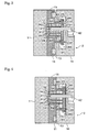
- FIG. 1 is a schematic sectional view showing a state in which the die is opened.
- the first die 1 is formed in a rectangular or other shape in the same manner as a conventional die, and a shape for forming the surface of the injection-compression molded article is carved into the surface of the first die 1 facing the second die 2.
- the second die 2 is formed as a rectangle or other shape whose width and height correspond to the first die 1.
- a compression block 12 in which a shape is carved for forming the back surface of the injection-compression molded article is attached to the surface of the second die 2 facing the first die 1.
- An external peripheral plate 11 for forming the external peripheral shape of the injection-compression molded article is provided to the external periphery of the compression block 12.
- the external peripheral plate 11 is formed as a rectangle or other shape whose width and height correspond to the first die 1, in the same manner as the second die 2.
- the compression block 12 forms the entire back surface of the injection-compression molded article.
- the compression block 12 may partially form the back surface of the injection-compression molded article, and the remaining portion may be formed by the external peripheral plate 11.
- a working space 60 is present inside a second die body 14.
- the front-side barrier wall 61 constituting a portion of the working space 60 has ejector pin insertion holes 62 and insertion holes 63 for the ejector plate fixing pins.
- the compression block 12 is fixedly supported on the outside of the front-side barrier wall 61.
- the compression block 12 has ejector pin insertion holes 64 communicated with the ejector pin insertion holes 62 of the front-side barrier wall 61.
- the external peripheral plate 11 capable of separating from and contacting the front-side barrier wall 61 is disposed on the external periphery of the compression block 12 and can slide relative to the compression block 12.
- An ejector plate 21 is disposed in the working space 60 so as to be able to move forward and backward.
- Ejector pins 24 fixedly supported by the ejector plate 21 are placed through the ejector pin insertion holes 62 of the front-side barrier wall 61 and the ejector pin insertion holes 64 of the compression block 12.
- Ejector plate fixing pins 22 having anti-disconnect heads 65 at the backs thereof are inserted into the insertion holes 63 for the ejector plate fixing pins, and the distal ends thereof are fixedly supported by the external peripheral plate 11.
- Springs 23 wound on the ejector plate fixing pins 22 are provided between the ejector plate 21 and the front-side barrier wall 61.
- the external peripheral plate 11 and the second die body 14 are separated from each other at a prescribed distance of approximately 0.5 mm, for example, by an elastic body 13.
- FIG. 2 is a schematic sectional view showing the state immediately after the die is closed.
- the molding space 30 is formed by the first die 1, the external peripheral plate 11, and the compression block 12.
- the molding space 30 is formed by the first die 1 and the second die 2.
- the molding space 30 accommodates the ejector pins 24 for ejecting the injection-compression molded article from the second die 2, and a hole-forming bushing 25 for forming a hole in the injection-compression molded article.
- the ejector pins 24 and the hole-forming bushing 25 are disposed so as to partially protrude into the molding space 30.
- the external peripheral plate 11, the ejector pins 24, and the hole-forming bushing 25 are connected to each other, whereby the positional relationship of these three components to each other does not change when the positional relationship between the compression block 12 and the external peripheral plate 11 changes.
- a configuration is adopted whereby the positional relationship between the compression block 12 and the external peripheral plate 11 can change without a change in the positional relationship between the external peripheral plate 11, the ejector pins 24, and the hole-forming bushing 25.
- the upper surface of the hole-forming bushing 25 is in contact with the first die 1.
- FIG. 3 is a schematic sectional view showing the manner in which the molding resin is injected into the die.
- the molding resin 31 is injected into the molding space 30 through a gate unit 41 provided to the compression block 12.
- the gate unit 41 herein is composed of a valve gate (not shown in the drawing) of a hot runner 42. After the molding resin 31 is injected, the valve gate is closed.
- the gate unit 41 may be a pin gate of a cold runner. In the case of a valve gate of a hot runner 42, there is no backflow of resin through the gate during compression. This configuration is preferred since better compression molding effects can be obtained.
- the molding resin 31 may be a polystyrene-based resin, polyolefin-based resin, acrylonitrile/butadiene/styrene resin, acrylic resin, or other multi-purpose resin. These resins are not limiting, and it is also possible to use polyphenylene oxide/polystyrene resin, polycarbonate-based resin, polyacetal-based resin, polycarbonate-modified polyphenylene ether resin, polybutylene terephthalate resin, and other multi-purpose engineering resins, as well as polysulfone resin, polyphenylene sulfide-based resin, polyphenylene oxide-based resin, polyarylate resin, polyether imide resin, polyimide resin, liquid crystal polyester resin, polyallyl-based heat-resistant resin, and other super engineering resins.
- FIG. 4 is a schematic sectional view showing the manner in which the molding resin is compressed after being injected.
- the external peripheral plate 11 and the second die body 14 were until now separated by the expansion force of the elastic body 13.
- the elastic body 13 is compressed, and the external peripheral plate 11 and the second die body 14 are brought into contact with each other.
- the positional relationship between the external peripheral plate 11 and the compression block 12 therefore changes, and the molding resin 31 loaded into the molding space 30 is compressed by the compression block 12.
- the amount of compression created by the compression block 12 herein is commensurate with the distance by which the external peripheral plate 11 and the second die body 14 are separated from each other.
- a thin spacer/shim or other component not shown in the drawing may be used for fine adjustment of this distance.
- FIG. 5 is a schematic sectional view showing a state in which the compression block is withdrawn after the molding resin is compressed.
- the system changes from a state in which the external peripheral plate 11 and the second die body 14 are in contact with each other to a state in which the external peripheral plate 11 and the second die body 14 are again separated from each other by the expansion force of the elastic body 13.
- the relationship between the expansion force T1 of the elastic body 13 and the expansion force T2 of the spring 23 must be set so as to satisfy the relation T1 > T2 in order to establish a state in which the external peripheral plate 11 and the second die body 14 are again separated from each other.
- the volume of the molding space 30 is increased by the withdrawal of the compression block 12. At this time, the injection-compression molded article is fixed in position in the inside the molding space 30 by the ejector pins 24 and the hole-forming bushing 25.
- the ejector pins 24 and the compression block 12 are disposed so as to partially protrude into the molding space 30 as shown in FIG. 3 .
- the compression block 12 advances forward, the positional relationship between the compression block 12 and the external peripheral plate 11 can be varied without any change in the positional relationship between the external peripheral plate 11, the ejector pins 24, and the hole-forming bushing 25, as shown in FIG. 4 .
- the injection-compression molded article can therefore be molded in a state in which the ejector pins 24 and hole-forming bushing 25 are partially buried therein.
- the positional relationship between the compression block 12 and the external peripheral plate 11 can be varied without any change in the positional relationship between the external peripheral plate 11, the ejector pins 24, and the hole-forming bushing 25, as shown in FIG. 5 .
- the position of the injection-compression molded article inside the molding space 30 can therefore be accurately fixed by the ejector pins 24 and the hole-forming bushing 25 when the compression block 12 is withdrawn.
- the ejector pins 24 are provided at a distance in the vertical direction. The position of the injection-compression molded article can therefore be stably maintained.
- FIG. 6 is a schematic sectional view showing a state in which the die is opened after the compression block is withdrawn.
- FIG. 6 shows the manner in which the injection-compression molded article is retained by the ejector pins 24 and the hole-forming bushing 25.
- FIG. 7 is a schematic sectional view showing a state in which the injection-compression molded article is ejected by the ejector pins 24 after the die is opened.
- the ejector plate 21 is moved towards the first die 1 by an ejector plate operating mechanism (not shown in the drawing).
- Methods of operation such as operation by an air cylinder or operation by an ejector rod connected to the first die 1, for example, may be selected for the ejector plate operating mechanism.
- the spring 23 is contracted at this time, but the positions of the ejector plate fixing pins 22 and the external peripheral plate 11 are still maintained with respect to the second die body 14.
- the injection-compression molded article is ejected by the ejector pins 24 and the hole-forming bushing 25.
- the injection-compression molded article may then be obtained by an attraction method that uses suction from a product extraction robot, or by a capturing method or other existing means.
- This second embodiment uses the injection-compression molding die according to the present invention as a die for decoration performed simultaneously with injection-compression molding.
- the die for simultaneous injection-compression molding and decoration according the second embodiment will be described hereinafter based on the drawings. Structural aspects that are the same as those of the abovementioned first embodiment will not be described.
- FIG. 8 is a schematic sectional view showing a state in which the die is opened.
- a decoration sheet 3 is disposed between a first die 1 and a second die 2 that face each other.
- This decoration sheet 3 is formed from a base sheet 51, a decoration layer 50, and other components.
- the decoration layer 50 is composed of a design layer 52, an adhesive layer 53, and other layers (see FIG. 15 ), and is used when transfer of only the decoration layer 50 to the molding resin 31 is desired.
- FIG. 9 is a schematic sectional view showing the state immediately after the die is closed.
- the molding space 30 is formed by the first die 1, the decoration sheet 3 disposed in the first die 1, and the second die 2.
- the ejector pins 24 and the hole-forming bushing 25 are disposed so as to partially protrude into the molding space 30.
- FIG. 10 is a schematic sectional view showing the manner in which the molding resin is injected into the die.
- the molding resin 31 is loaded from the gate unit 41 into the molding space 30 enclosed by the decoration sheet 3, the external peripheral plate 11, and the compression block 12.
- the first die 1 and the second die 2 close across a gap P that corresponds to the thickness of the decoration sheet 3. Gas can therefore be released through the gap P during loading of the molding resin 31.
- FIG. 11 is a schematic sectional view showing the manner in which the molding resin is compressed after being injected.
- the volume inside the molding space 30 is reduced by the operation of the compression block 12.
- a state is maintained in which the ejector pins 24 and hole-forming bushing 25 do not move but partially protrude into the molding space 30. Gas can also be released during compression of the molding resin 31 through the gap P between the first die 1 and the second die 2.
- FIG. 12 is a schematic sectional view showing a state in which the compression block is withdrawn after the molding resin is compressed.
- the volume of the molding space 30 is increased by the withdrawal of the compression block 12.
- a state is maintained in which the ejector pins 24 and hole-forming bushing 25 do not move but partially protrude into the molding space 30.
- the simultaneously injection-compression molded and decorated article thus molded is therefore fixed in position inside the molding space 30 by the ejector pins 24 and the hole-forming bushing 25.
- FIG. 13 is a schematic sectional view showing a state in which the die is opened after the compression block is withdrawn.
- FIG. 13 shows the manner in which the simultaneously injection-compression molded and decorated article is retained by the ejector pins 24 and the hole-forming bushing 25 in a state in which the decoration layer 50 of the decoration sheet 3 is peeled from the base sheet 51 and transferred to the molding resin 31.
- FIG. 14 is a schematic sectional view showing a state in which the simultaneously injection-compression molded and decorated article is ejected by the ejector pins 24 after the die is opened.
- the ejector plate 21 is moved towards the first die 1 by an ejector plate operating mechanism (not shown in the drawing). As the ejector plate 21 moves, the simultaneously injection-compression molded and decorated article is ejected by the ejector pins 24 and the hole-forming bushing 25.
- FIG. 15 is a schematic sectional view showing the structure of the transfer film as the decoration sheet 3 used in the die according to the second embodiment.
- PET polyethylene terephthalate
- PET polyethylene terephthalate
- a single-layer film selected from polycarbonate resin, polyamide resin, polyimide resin, polyester resin, acrylic resin, olefin resin, urethane resin, acrylonitrile butadiene styrene resin, vinyl chloride resin, and the like. It is also possible to use a laminate film or copolymer film composed of two or more types of resin selected from the resins mentioned above.
- a base sheet 51 having a thickness of 5 to 500 ⁇ m may be used.
- a base sheet 51 having a thickness of 25 to 75 ⁇ m is preferred when ease of handling is considered.
- a base sheet 51 having a thickness of 38 to 50 ⁇ m is preferably used when molding stability is considered.
- the peeling layer 54 becomes the outermost surface when the base sheet 51 is peeled off after the design is transferred, and functions as a protective layer for the design.
- Materials used for this peeling layer 54 include acrylic-based resin, soluble-cotton-based resin, polyurethane-based resin, chlorinated-rubber-based resin, vinyl chloride-vinyl acetate copolymer-based resin, polyamide-based resin, polyester-based resin, epoxy-based resin, polycarbonate-based resin, olefin-based resin, acrylonitrile butadiene styrene resin, and the like.
- the film thickness of the peeling layer 54 is preferably 0.5 to 50 ⁇ m.
- the release layer 55 is a surface-treated layer on the base sheet 51. This release layer 55 is provided to facilitate peeling of the peeling layer 54 from the base sheet 51. Therefore, this release layer 55 may be omitted when peeling can be accomplished using only the base sheet 51 and the peeling layer 54. The same material as the peeling layer 54 may be used to form the release layer 55.
- the design layer 52 that includes letters, symbols, designs, coated patterns, and the like is sealed between the peeling layer 54 and the adhesive layer 53.
- Materials used for this design layer 52 may include acrylic-based resin, soluble-cotton-based resin, polyurethane-based resin, chlorinated-rubber-based resin, vinyl chloride-vinyl acetate copolymer-based resin, polyamide-based resin, polyester-based resin, epoxy-based resin, and the like.
- the design layer 52 may also be formed from aluminum, chromium, copper, nickel, indium, tin, silicon oxide, or another metal film layer, for example, by vacuum deposition, plating, or another method.
- the film thickness of the design layer 52 is preferably set to a range of 0.5 ⁇ m to 50 ⁇ m in order to obtain adequate design properties.
- a thickness of 50 ⁇ to 1200 ⁇ is preferred.
- the adhesive layer 53 is provided to bond the design layer 52 to the surface of the molded article.
- the material used therein may include acrylic-based resin, soluble-cotton-based resin, polyurethane-based resin, chlorinated-rubber-based resin, vinyl chloride-vinyl acetate copolymer-based resin, polyamide-based resin, polyester-based resin, epoxy-based resin, polycarbonate-based resin, olefin-based resin, acrylonitrile butadiene styrene resin, or the like.
- the thickness of this adhesive layer 53 is preferably 0.5 to 50 ⁇ m.
- decoration was performed using a transfer film, but a decoration film may also be used.
- a decoration film a design layer is formed directly on a base film without using a peeling layer. After decoration, the base film is integrated with the simultaneously injection-compression molded and decorated article.
- a decoration film base sheet 51 having a thickness of 25 to 1000 ⁇ m may be used.
- a decoration film base sheet 51 having a thickness of 50 to 600 ⁇ m is preferably used when handling properties are considered.
- a decoration film base sheet 51 having a thickness of 100 to 500 ⁇ m is preferably used.
- a mobile telephone part that is made of acrylic resin has an outside longitudinal dimension of approximately 50 mm, a transverse dimension of approximately 40 mm, and an average thickness of approximately 0.8 mm, and is provided with a hole near the bottom of the product was formed using the die for simultaneous injection-compression molding and decoration according to the second embodiment.
- the amount of compression produced by the compression block operation of this die was approximately 0.5 mm, and the gate unit was a hot runner valve gate.
- This third embodiment is a modification of the abovementioned second embodiment.
- the die for simultaneous injection-compression molding and decoration according to the third embodiment will be described hereinafter based on the drawings. Structural aspects that are the same as those of the abovementioned second embodiment will not be described.
- FIG. 16 is a schematic sectional view showing a state in which the die is opened.
- the first die 1 is provided with a suction means 70 for drawing in the decoration sheet 3 disposed between the first die 1 and the second die 2.
- the suction means 70 is composed of a communicating portion 71 that is communicated with a die cavity 1a for the molding space formed in the first die 1, and a suction device 72 for drawing in air through the communicating portion 71.
- the suction means 70 draws in the decoration sheet 3, whereby the decoration sheet 3 can be maintained in a state of conformity to the die cavity 1a.
- the decoration sheet 3 can therefore be prevented from deforming during loading of the molding resin 31.
- the present invention may be applied to various types of injection-compression molding dies for obtaining an injection-compression molded article by loading molten molding resin from a gate unit into a molding space formed by a first die and a second die that face each other, and then reducing the volume of the molding space to compress the loaded molding resin, and curing the molding resin.
Landscapes
- Engineering & Computer Science (AREA)
- Manufacturing & Machinery (AREA)
- Mechanical Engineering (AREA)
- Moulds For Moulding Plastics Or The Like (AREA)
- Injection Moulding Of Plastics Or The Like (AREA)
Abstract
Description
- The present invention relates to a die for injection-compression molding, and particularly relates to a die for decoration simultaneous with injection-compression molding whereby an article is decorated simultaneously with injection-compression molding, has excellent optical characteristics, and does not need post-processing.
- Conventional methods for decorating the surface of a resin molding include an injection-molding-simultaneous decoration method that utilizes a transfer material, an IMD (registered trademark: Nissha Printing Co., Ltd.) foil, or other decoration sheet. The range of utilization of the injection-molding-simultaneous decoration method has significantly increased in recent years. This injection-molding-simultaneous decoration method is also applied to products such as mobile telephone window panels in which a transparent portion extends over a wide range of the surface of a molded article. In this case, good optical characteristics must be provided in order for an internal liquid crystal panel to show through the transparent portion.
- With recent demand for reduced wall thickness (1 mm or less, for example) of molded articles, it is becoming difficult to adapt the usual injection-molding-simultaneous decoration method in use until now. There is therefore a desire for the establishment of a production method in which an injection-molding-simultaneous decoration method is combined with an injection-compression molding method. An injection-compression molding method can produce enhanced transfer properties, reduced weld lines, reduced shrinkage, reduced deformation, and enhanced optical characteristics compared to the usual injection molding method. This method has therefore been utilized for molding precision components, manufacturing optical lenses, CDs, and DVDs, and other products.
- The die described in
Patent Document 1 is a technique relating to an injection-molding-simultaneous decoration method for producing a mobile telephone window panel or other thin-walled molded article. The die described inPatent Document 2 is a technique relating to an injection-compression molding method. - [Patent Document 1]
Japanese Laid-open Patent Application No. 2004-314611
[Patent Document 2]Japanese Laid-open Patent Application No. 11-179769 - In the die described in
Patent Document 1, a molding space formed by a first die and a second die comprises a product molding space, a molding space for resin injection, and a molding space for resin discharge. Resin is therefore molded not only in the product molding space, but also in the molding space for resin discharge. Consequently, in order to obtain the desired molding, the unnecessary portions molded on the periphery of the product must be cut off in post-processing.
In the die described inPatent Document 2, a side-gate system is employed by a gate unit used for injecting the molding resin. Consequently, traces of the side gate must be cut from the product in order to obtain the desired molding.
The dies according toPatent Document 1 andPatent Document 2 as described above have drawbacks of impracticality due to manufacturing cost. - Noting that the drawbacks of the die described in
Patent Document 2 are caused by the side-gate system, the inventors investigated the possibility of changing to another gate system, such as a pin gate system or a hot runner valve gate system, for example, but encountered the drawbacks described below. - In a pin-gate or hot-runner-valve-gate die, the product is generally ejected after die opening by an ejector pin pushing on the surface of the product. When these systems are applied to an injection-compression molding die in the same manner as a conventional die, a state occurs after molding of the injection-compression molded article in which the internal volume of the molding space is increased by the withdrawal of the compression block. At this time, the injection-compression-molded article moves in conjunction with the withdrawal of the compression block. As a result, there is a risk that excessive force will be applied to the external periphery of the injection-compression-molded article, that damage will occur on the surface of the injection-compression-molded article, and that the injection-compression-molded article will be deformed.
- The abovementioned drawbacks will be described using an example of a case in which an injection-compression molding die is used as a die for simultaneous injection-compression molding and decoration, as shown in
FIG. 17 .
Adecoration sheet 3 is disposed between afirst die 1 and asecond die 2, and amolding resin 31 is loaded between thedecoration sheet 3 and thesecond die 2 from agate unit 41. Thesecond die 2 has acompression block 12 for reducing the volume of amolding space 30 and compressing the loadedmolding resin 31, an externalperipheral plate 11 positioned on the periphery of thecompression block 12, andejector pins 24 for ejecting the simultaneously injection-compression molded and decorated article from thesecond die 2. Theejector pins 24 are fixedly supported by anejector plate 21 disposed so as to be able to move back and forth in a workingspace 60 inside thesecond die 2. Theejector pins 24 are provided so as to move integrally with thecompression block 12 when the positions of thecompression block 12 and the externalperipheral plate 11 change relative to each other.
After themolding resin 31 is compressed by thecompression block 12, and the simultaneously injection-compression molded and decorated article is molded, thecompression block 12 is withdrawn, and the positional relationship of thecompression block 12 relative to the externalperipheral plate 11 is changed. Theejector pins 24 move integrally with thecompression block 12 at this time, and theejector pins 24 separate from the simultaneously injection-compression molded and decorated article. The simultaneously injection-compression molded and decorated article therefore becomes able to move inside themolding space 30, and its position becomes unstable. - An object of the present invention is to provide a die for injection-compression molding that is capable of maintaining the position of the injection-compression molded article inside the molding space after molding.
- The inventors developed the present invention as a result of conducting further research in view of the foregoing drawbacks, and investigating the use of a method for compression molding whereby the compression block is advanced so as to reduce the volume inside the molding space while the external periphery of the product is enclosed by an external peripheral plate.
Specifically, the present invention is configured as described below in order to achieve the aforementioned objects. - According to a first aspect of the present invention, in an injection-compression molding die for obtaining an injection-compression molded article by loading molten molding resin into a molding space, formed by a first die and a second die that face each other, through a molding resin injection gate unit provided to the second die, and then reducing the volume of the molding space to compress the loaded molding resin, and curing the molding resin, the injection-compression molding die is configured so that a compression block for reducing the volume of the molding space and compressing the loaded molding resin, and an external peripheral plate positioned on the external periphery of the compression block are provided to the first die or the second die; and the positional relationship between the compression block and the external peripheral plate can be varied without changing the positional relationship between the external peripheral plate and an ejector pin for ejecting the injection-compression molded article from the first die or the second die.
- According to a second aspect of the present invention, the ejector pin is disposed so as to partially protrude into the molding space during loading of the molding resin.
- According to a third aspect of the present invention, the compression block, the external peripheral plate, and the ejector pin is provided to the second die, and the ejector pin is provided so as to penetrate the compression block.
- According to a fourth aspect of the present invention, the second die has an internally disposed working space; the front-side barrier wall constituting a portion of the working space has an ejector pin insertion hole and an insertion hole for the ejector plate fixing pin; the compression block is fixedly supported on the outside of the front-side barrier wall; the compression block has an ejector pin insertion hole communicated with the ejector pin insertion hole of the front-side barrier wall; the external peripheral plate capable of separating from and contacting the front-side barrier wall is disposed on the external periphery of the compression block and can slide relative to the compression block; an ejector plate is disposed in the working space so as to be able to move forward and backward; the ejector pin fixedly supported by the ejector plate is placed through the ejector pin insertion hole of the front-side barrier wall and the ejector pin insertion hole of the compression block; ejector plate fixing pin having an anti-disconnect head at the back thereof is inserted into the ejector plate fixing pin insertion hole, the distal end thereof being fixedly supported by the external peripheral plate; and springs wound on the ejector plate fixing pin is provided between the ejector plate and the front-side barrier wall.
- According to a fifth aspect of the present invention, the second die further comprises a hole-forming bushing that passes through the compression block; and the positional relationship between the compression block and the external peripheral plate can be varied without changing the positional relationship between the external peripheral plate, the ejector pin, and the hole-forming bushing.
- According to a sixth aspect of the present invention, the first die comprises suction means for drawing in a decoration sheet disposed between the first die and the second die.
- According to a seventh aspect of the present invention, the first die and the second die close across a gap that corresponds to the thickness of the decoration sheet in a state in which the decoration sheet is disposed between the first die and the second die that face each other.
- According to the first aspect of the present invention, the positional relationship between the compression block and the external peripheral plate can be varied without changing the positional relationship between the external peripheral plate and the ejector pin, particularly when the compression block is withdrawn after compression of the molding resin. A state in which the injection-compression molded article is retained by the ejector pin can therefore be maintained even when the compression block is withdrawn and the volume of the molding space is increased. As a result, the desired position can be maintained without movement of the injection-compression molded article inside the molding space.
In a case in which the gate unit is provided to the compression block, the gate unit and the transfer film are separated from each other at a distance of about 1.5 mm during injection of the molding resin when the decoration sheet is disposed between the first die and the second die. The risk of defects occurring due to ink flow is therefore reduced even when the injection-compression molded article has a small wall thickness of about 1 mm. - According to the second aspect of the present invention, a configuration is adopted whereby the ejector pin partially protrude into the molding space during loading of the molding resin. During compression of the molding resin, the compression block can be pushed in with respect to the external peripheral plate without changing the positional relationship between the external peripheral plate and the ejector pin. An injection-compression molded article can therefore be molded in a state in which portions of the ejector pin is buried. When the compression block is subsequently withdrawn, only the compression block moves with respect to the external peripheral plate, and the positional relationship between the external peripheral plate and the ejector pin is unchanged. A portion of the ejector pin is therefore buried in the injection-compression molded article, and the article can be reliably retained by the ejector pin.
- According to the third aspect of the present invention, the side on which the compression block compresses and the ejector pin protrudes constitutes the side of the injection-compression molded article that faces the second die. The injection-compression molded article can therefore be molded without damaging the side of the article that faces the first die. When a simultaneously injection-compression molded and decorated article is molded using a decoration sheet, the simultaneously injection-compression molded and decorated article can be molded without damage to the decoration sheet by placing the decoration sheet closer to the first die than to the loaded molding resin.
- According to the fourth aspect of the present invention, the ejector pin is fixedly supported by the ejector plate, and ejector plate fixing pin having an anti-disconnect head at the back thereof are inserted into the insertion holes for the ejector plate fixing pin, the distal ends thereof being fixedly supported by the external peripheral plate. The positional relationship between the compression block and the external peripheral plate can therefore be varied without changing the positional relationship between the external peripheral plate and the ejector pin. As a result, a state in which the injection-compression molded article is retained by the ejector pin can therefore be maintained even when the compression block is withdrawn and the volume of the molding space is increased, and the desired position can be maintained without movement of the injection-compression molded article inside the molding space.
- According to the fifth aspect of the present invention, an injection-compression molded article having a hole portion can be obtained by further providing a hole-forming bushing whereby the second die penetrates the compression block. The hole-forming bushing is disposed so that a portion thereof protrudes into the molding space during loading of the molding resin. The positional relationship between the compression block and the external peripheral plate can be varied without changing the positional relationship between the external peripheral plate and the hole-forming bushing during compression of the molding resin. An injection-compression molded article can therefore be molded in a state in which a portion of the hole-forming bushing is buried. Then, when the compression block is withdrawn, only the compression block moves with respect to the external peripheral plate, and the positional relationship between the external peripheral plate and the hole-forming bushing is unchanged. The article can therefore be retained by the hole-forming bushing in addition to the ejector pin. As a result, the injection-compression molded article can be stably fixed in position inside the molding space.
- According to the sixth aspect of the present invention, the decoration sheet can be retained in a state of conformity with the first die by using the suction means to draw in the decoration sheet. Deformation of the decoration sheet during loading of the molding resin can therefore be minimized, and a satisfactory simultaneously injection-compression molded and decorated article can be molded.
- According to the seventh aspect of the present invention, a gap corresponding to the thickness of the decoration sheet can be provided between the first die and the second die during loading of the molding resin and compression of the molding resin. Gas can therefore be released from the gap between the first die and the second die during loading and compression of the molding resin, and a satisfactory simultaneously injection-compression molded and decorated article can be molded.
- Embodiments of the injection-compression molding die according to the present invention will be described hereinafter.
- The injection-compression molding die according to a first embodiment will first be described based on the drawings.
FIG. 1 is a schematic sectional view showing a state in which the die is opened.
InFIG. 1 , thefirst die 1 is formed in a rectangular or other shape in the same manner as a conventional die, and a shape for forming the surface of the injection-compression molded article is carved into the surface of thefirst die 1 facing thesecond die 2. - The
second die 2 is formed as a rectangle or other shape whose width and height correspond to thefirst die 1. Acompression block 12 in which a shape is carved for forming the back surface of the injection-compression molded article is attached to the surface of thesecond die 2 facing thefirst die 1. An externalperipheral plate 11 for forming the external peripheral shape of the injection-compression molded article is provided to the external periphery of thecompression block 12. The externalperipheral plate 11 is formed as a rectangle or other shape whose width and height correspond to thefirst die 1, in the same manner as thesecond die 2. In this drawing, thecompression block 12 forms the entire back surface of the injection-compression molded article. Thecompression block 12 may partially form the back surface of the injection-compression molded article, and the remaining portion may be formed by the externalperipheral plate 11. - The structure of the
second die 2 will be described in further detail. A workingspace 60 is present inside asecond die body 14. The front-side barrier wall 61 constituting a portion of the workingspace 60 has ejector pin insertion holes 62 and insertion holes 63 for the ejector plate fixing pins. Thecompression block 12 is fixedly supported on the outside of the front-side barrier wall 61. Thecompression block 12 has ejector pin insertion holes 64 communicated with the ejector pin insertion holes 62 of the front-side barrier wall 61. The externalperipheral plate 11 capable of separating from and contacting the front-side barrier wall 61 is disposed on the external periphery of thecompression block 12 and can slide relative to thecompression block 12. Anejector plate 21 is disposed in the workingspace 60 so as to be able to move forward and backward. Ejector pins 24 fixedly supported by theejector plate 21 are placed through the ejector pin insertion holes 62 of the front-side barrier wall 61 and the ejector pin insertion holes 64 of thecompression block 12. Ejector plate fixing pins 22 having anti-disconnect heads 65 at the backs thereof are inserted into the insertion holes 63 for the ejector plate fixing pins, and the distal ends thereof are fixedly supported by the externalperipheral plate 11.Springs 23 wound on the ejector plate fixing pins 22 are provided between theejector plate 21 and the front-side barrier wall 61. The externalperipheral plate 11 and thesecond die body 14 are separated from each other at a prescribed distance of approximately 0.5 mm, for example, by anelastic body 13. -
FIG. 2 is a schematic sectional view showing the state immediately after the die is closed.
InFIG. 2 , themolding space 30 is formed by thefirst die 1, the externalperipheral plate 11, and thecompression block 12. Specifically, themolding space 30 is formed by thefirst die 1 and thesecond die 2. Themolding space 30 accommodates the ejector pins 24 for ejecting the injection-compression molded article from thesecond die 2, and a hole-formingbushing 25 for forming a hole in the injection-compression molded article. Specifically, the ejector pins 24 and the hole-formingbushing 25 are disposed so as to partially protrude into themolding space 30. The externalperipheral plate 11, the ejector pins 24, and the hole-formingbushing 25 are connected to each other, whereby the positional relationship of these three components to each other does not change when the positional relationship between thecompression block 12 and the externalperipheral plate 11 changes. Specifically, a configuration is adopted whereby the positional relationship between thecompression block 12 and the externalperipheral plate 11 can change without a change in the positional relationship between the externalperipheral plate 11, the ejector pins 24, and the hole-formingbushing 25. The upper surface of the hole-formingbushing 25 is in contact with thefirst die 1. -
FIG. 3 is a schematic sectional view showing the manner in which the molding resin is injected into the die.
InFIG. 3 , themolding resin 31 is injected into themolding space 30 through agate unit 41 provided to thecompression block 12. Thegate unit 41 herein is composed of a valve gate (not shown in the drawing) of ahot runner 42. After themolding resin 31 is injected, the valve gate is closed. - The
gate unit 41 may be a pin gate of a cold runner. In the case of a valve gate of ahot runner 42, there is no backflow of resin through the gate during compression. This configuration is preferred since better compression molding effects can be obtained. - The
molding resin 31 may be a polystyrene-based resin, polyolefin-based resin, acrylonitrile/butadiene/styrene resin, acrylic resin, or other multi-purpose resin. These resins are not limiting, and it is also possible to use polyphenylene oxide/polystyrene resin, polycarbonate-based resin, polyacetal-based resin, polycarbonate-modified polyphenylene ether resin, polybutylene terephthalate resin, and other multi-purpose engineering resins, as well as polysulfone resin, polyphenylene sulfide-based resin, polyphenylene oxide-based resin, polyarylate resin, polyether imide resin, polyimide resin, liquid crystal polyester resin, polyallyl-based heat-resistant resin, and other super engineering resins. -
FIG. 4 is a schematic sectional view showing the manner in which the molding resin is compressed after being injected.
InFIG. 4 , the externalperipheral plate 11 and thesecond die body 14 were until now separated by the expansion force of theelastic body 13. As a die-closing force larger than this expansion force is applied, theelastic body 13 is compressed, and the externalperipheral plate 11 and thesecond die body 14 are brought into contact with each other. The positional relationship between the externalperipheral plate 11 and thecompression block 12 therefore changes, and themolding resin 31 loaded into themolding space 30 is compressed by thecompression block 12. - The amount of compression created by the
compression block 12 herein is commensurate with the distance by which the externalperipheral plate 11 and thesecond die body 14 are separated from each other. For example, a thin spacer/shim or other component not shown in the drawing may be used for fine adjustment of this distance. - There is no change in the positional relationship between the external
peripheral plate 11, the ejector pins 24 passed through thecompression block 12 and fixed to theejector plate 21, and the hole-formingbushing 25. This is because the positional relationship between the externalperipheral plate 11 and theejector plate 21 is maintained by the ejector plate fixing pins 22 and the expansion force of thespring 23 even when there is only a small distance between the externalperipheral plate 11 and thesecond die body 14.
Specifically, the volume inside themolding space 30 is reduced by the operation of thecompression block 12, but the ejector pins 24 and the hole-formingbushing 25 can be considered unmoved. Therefore, the application of excessive force to the injection-compression molded article by the movement of the ejector pins 24 can be prevented with essentially no change in the positional relationship between themolding resin 31 and the ejector pins 24, and a satisfactory injection-compression molded article can be obtained. -
FIG. 5 is a schematic sectional view showing a state in which the compression block is withdrawn after the molding resin is compressed.
InFIG. 5 , when the die-opening operation of the molding machine (not shown in the drawing) is performed, the system changes from a state in which the externalperipheral plate 11 and thesecond die body 14 are in contact with each other to a state in which the externalperipheral plate 11 and thesecond die body 14 are again separated from each other by the expansion force of theelastic body 13. - In this arrangement, the relationship between the expansion force T1 of the
elastic body 13 and the expansion force T2 of thespring 23 must be set so as to satisfy the relation T1 > T2 in order to establish a state in which the externalperipheral plate 11 and thesecond die body 14 are again separated from each other. - As the state occurs in which the external
peripheral plate 11 and thesecond die body 14 are separated from each other, the positional relationship between the externalperipheral plate 11 and thecompression block 12 changes. The positional relationship between the externalperipheral plate 11 and theejector plate 21 is not changed at this time by the ejector plate fixing pins 22 and the expansion force of thespring 23. There is therefore also no change in the positional relationship between the externalperipheral plate 11, the ejector pins 24, and the hole-formingbushing 25. - The volume of the
molding space 30 is increased by the withdrawal of thecompression block 12. At this time, the injection-compression molded article is fixed in position in the inside themolding space 30 by the ejector pins 24 and the hole-formingbushing 25. - The movement of the ejector pins 24 and the
compression block 12 relative to each other will be further described.
During loading of themolding resin 31, the ejector pins 24 and the hole-formingbushing 25 are disposed so as to partially protrude into themolding space 30 as shown inFIG. 3 . When thecompression block 12 advances forward, the positional relationship between thecompression block 12 and the externalperipheral plate 11 can be varied without any change in the positional relationship between the externalperipheral plate 11, the ejector pins 24, and the hole-formingbushing 25, as shown inFIG. 4 . The injection-compression molded article can therefore be molded in a state in which the ejector pins 24 and hole-formingbushing 25 are partially buried therein. When thecompression block 12 is withdrawn, the positional relationship between thecompression block 12 and the externalperipheral plate 11 can be varied without any change in the positional relationship between the externalperipheral plate 11, the ejector pins 24, and the hole-formingbushing 25, as shown inFIG. 5 . The position of the injection-compression molded article inside themolding space 30 can therefore be accurately fixed by the ejector pins 24 and the hole-formingbushing 25 when thecompression block 12 is withdrawn. The ejector pins 24 are provided at a distance in the vertical direction. The position of the injection-compression molded article can therefore be stably maintained. -
FIG. 6 is a schematic sectional view showing a state in which the die is opened after the compression block is withdrawn.
FIG. 6 shows the manner in which the injection-compression molded article is retained by the ejector pins 24 and the hole-formingbushing 25. -
FIG. 7 is a schematic sectional view showing a state in which the injection-compression molded article is ejected by the ejector pins 24 after the die is opened.
InFIG. 7 , theejector plate 21 is moved towards thefirst die 1 by an ejector plate operating mechanism (not shown in the drawing). Methods of operation such as operation by an air cylinder or operation by an ejector rod connected to thefirst die 1, for example, may be selected for the ejector plate operating mechanism.
Thespring 23 is contracted at this time, but the positions of the ejector plate fixing pins 22 and the externalperipheral plate 11 are still maintained with respect to thesecond die body 14. - As the
ejector plate 21 moves, the injection-compression molded article is ejected by the ejector pins 24 and the hole-formingbushing 25. The injection-compression molded article may then be obtained by an attraction method that uses suction from a product extraction robot, or by a capturing method or other existing means. - This second embodiment uses the injection-compression molding die according to the present invention as a die for decoration performed simultaneously with injection-compression molding. The die for simultaneous injection-compression molding and decoration according the second embodiment will be described hereinafter based on the drawings. Structural aspects that are the same as those of the abovementioned first embodiment will not be described.
-
FIG. 8 is a schematic sectional view showing a state in which the die is opened.
InFIG. 8 , adecoration sheet 3 is disposed between afirst die 1 and asecond die 2 that face each other. Thisdecoration sheet 3 is formed from abase sheet 51, adecoration layer 50, and other components. Thedecoration layer 50 is composed of adesign layer 52, anadhesive layer 53, and other layers (seeFIG. 15 ), and is used when transfer of only thedecoration layer 50 to themolding resin 31 is desired. -
FIG. 9 is a schematic sectional view showing the state immediately after the die is closed.
InFIG. 9 , themolding space 30 is formed by thefirst die 1, thedecoration sheet 3 disposed in thefirst die 1, and thesecond die 2. The ejector pins 24 and the hole-formingbushing 25 are disposed so as to partially protrude into themolding space 30. -
FIG. 10 is a schematic sectional view showing the manner in which the molding resin is injected into the die.
InFIG. 10 , themolding resin 31 is loaded from thegate unit 41 into themolding space 30 enclosed by thedecoration sheet 3, the externalperipheral plate 11, and thecompression block 12. Thefirst die 1 and thesecond die 2 close across a gap P that corresponds to the thickness of thedecoration sheet 3. Gas can therefore be released through the gap P during loading of themolding resin 31. -
FIG. 11 is a schematic sectional view showing the manner in which the molding resin is compressed after being injected.
InFIG. 11 , the volume inside themolding space 30 is reduced by the operation of thecompression block 12. At this time, a state is maintained in which the ejector pins 24 and hole-formingbushing 25 do not move but partially protrude into themolding space 30. Gas can also be released during compression of themolding resin 31 through the gap P between thefirst die 1 and thesecond die 2. -
FIG. 12 is a schematic sectional view showing a state in which the compression block is withdrawn after the molding resin is compressed.
InFIG. 12 , the volume of themolding space 30 is increased by the withdrawal of thecompression block 12. At this time, a state is maintained in which the ejector pins 24 and hole-formingbushing 25 do not move but partially protrude into themolding space 30. The simultaneously injection-compression molded and decorated article thus molded is therefore fixed in position inside themolding space 30 by the ejector pins 24 and the hole-formingbushing 25. -
FIG. 13 is a schematic sectional view showing a state in which the die is opened after the compression block is withdrawn.
FIG. 13 shows the manner in which the simultaneously injection-compression molded and decorated article is retained by the ejector pins 24 and the hole-formingbushing 25 in a state in which thedecoration layer 50 of thedecoration sheet 3 is peeled from thebase sheet 51 and transferred to themolding resin 31. -
FIG. 14 is a schematic sectional view showing a state in which the simultaneously injection-compression molded and decorated article is ejected by the ejector pins 24 after the die is opened.
InFIG. 14 , theejector plate 21 is moved towards thefirst die 1 by an ejector plate operating mechanism (not shown in the drawing). As theejector plate 21 moves, the simultaneously injection-compression molded and decorated article is ejected by the ejector pins 24 and the hole-formingbushing 25. -
FIG. 15 is a schematic sectional view showing the structure of the transfer film as thedecoration sheet 3 used in the die according to the second embodiment. - PET (polyethylene terephthalate) having excellent heat resistance is preferably used as the material of the
base sheet 51. It is possible to use a single-layer film selected from polycarbonate resin, polyamide resin, polyimide resin, polyester resin, acrylic resin, olefin resin, urethane resin, acrylonitrile butadiene styrene resin, vinyl chloride resin, and the like. It is also possible to use a laminate film or copolymer film composed of two or more types of resin selected from the resins mentioned above.
Abase sheet 51 having a thickness of 5 to 500 µm may be used. Abase sheet 51 having a thickness of 25 to 75 µm is preferred when ease of handling is considered. Abase sheet 51 having a thickness of 38 to 50 µm is preferably used when molding stability is considered. - The
peeling layer 54 becomes the outermost surface when thebase sheet 51 is peeled off after the design is transferred, and functions as a protective layer for the design.
Materials used for thispeeling layer 54 include acrylic-based resin, soluble-cotton-based resin, polyurethane-based resin, chlorinated-rubber-based resin, vinyl chloride-vinyl acetate copolymer-based resin, polyamide-based resin, polyester-based resin, epoxy-based resin, polycarbonate-based resin, olefin-based resin, acrylonitrile butadiene styrene resin, and the like. The film thickness of thepeeling layer 54 is preferably 0.5 to 50 µm. - The
release layer 55 is a surface-treated layer on thebase sheet 51. Thisrelease layer 55 is provided to facilitate peeling of thepeeling layer 54 from thebase sheet 51. Therefore, thisrelease layer 55 may be omitted when peeling can be accomplished using only thebase sheet 51 and thepeeling layer 54. The same material as thepeeling layer 54 may be used to form therelease layer 55. - The
design layer 52 that includes letters, symbols, designs, coated patterns, and the like is sealed between the peelinglayer 54 and theadhesive layer 53. Materials used for thisdesign layer 52 may include acrylic-based resin, soluble-cotton-based resin, polyurethane-based resin, chlorinated-rubber-based resin, vinyl chloride-vinyl acetate copolymer-based resin, polyamide-based resin, polyester-based resin, epoxy-based resin, and the like. - The
design layer 52 may also be formed from aluminum, chromium, copper, nickel, indium, tin, silicon oxide, or another metal film layer, for example, by vacuum deposition, plating, or another method. The film thickness of thedesign layer 52 is preferably set to a range of 0.5 µm to 50 µm in order to obtain adequate design properties. When thedesign layer 52 is formed from a metal film layer, a thickness of 50 Å to 1200 Å is preferred. - The
adhesive layer 53 is provided to bond thedesign layer 52 to the surface of the molded article. The material used therein may include acrylic-based resin, soluble-cotton-based resin, polyurethane-based resin, chlorinated-rubber-based resin, vinyl chloride-vinyl acetate copolymer-based resin, polyamide-based resin, polyester-based resin, epoxy-based resin, polycarbonate-based resin, olefin-based resin, acrylonitrile butadiene styrene resin, or the like. The thickness of thisadhesive layer 53 is preferably 0.5 to 50 µm. - In this second embodiment, decoration was performed using a transfer film, but a decoration film may also be used. In a decoration film, a design layer is formed directly on a base film without using a peeling layer. After decoration, the base film is integrated with the simultaneously injection-compression molded and decorated article.
- A decoration
film base sheet 51 having a thickness of 25 to 1000 µm may be used. A decorationfilm base sheet 51 having a thickness of 50 to 600 µm is preferably used when handling properties are considered. When molding stability is considered, a decorationfilm base sheet 51 having a thickness of 100 to 500 µm is preferably used. - A mobile telephone part that is made of acrylic resin, has an outside longitudinal dimension of approximately 50 mm, a transverse dimension of approximately 40 mm, and an average thickness of approximately 0.8 mm, and is provided with a hole near the bottom of the product was formed using the die for simultaneous injection-compression molding and decoration according to the second embodiment. The amount of compression produced by the compression block operation of this die was approximately 0.5 mm, and the gate unit was a hot runner valve gate.
- There was no variation in the dimensions of the molded article continuously molded using a product extraction robot, and the ability to consistently produce a molded article was confirmed. There was, of course, no need to perform post-processing that involved gate cutting for the external periphery of the molded article.
- Ink flow did not occur near the gate unit of this molded article, and there were no problems related to the appearance of the product. Even when the transparent window portion of the molded article was observed through a polarizing plate, internal stress usually seen near the gate unit was not observed, and superior optical characteristics were confirmed.
- This third embodiment is a modification of the abovementioned second embodiment. The die for simultaneous injection-compression molding and decoration according to the third embodiment will be described hereinafter based on the drawings. Structural aspects that are the same as those of the abovementioned second embodiment will not be described.
-
FIG. 16 is a schematic sectional view showing a state in which the die is opened.
InFIG. 16 , thefirst die 1 is provided with a suction means 70 for drawing in thedecoration sheet 3 disposed between thefirst die 1 and thesecond die 2. The suction means 70 is composed of a communicatingportion 71 that is communicated with adie cavity 1a for the molding space formed in thefirst die 1, and asuction device 72 for drawing in air through the communicatingportion 71. The suction means 70 draws in thedecoration sheet 3, whereby thedecoration sheet 3 can be maintained in a state of conformity to thedie cavity 1a. Thedecoration sheet 3 can therefore be prevented from deforming during loading of themolding resin 31. - [Other Embodiments]
- (1) In the first through third embodiments described above, the
compression block 12, externalperipheral plate 11, and ejector pins 24 are provided to thesecond die 2. Instead of this configuration, thecompression block 12, externalperipheral plate 11, and ejector pins 24 may be provided to thefirst die 1. -
- (2) In the first through third embodiments described above, ejector pins 24 are provided at a distance in the vertical direction, but the number of ejector pins 24 may be appropriately changed. The position in which the ejector pins 24 are disposed may also be appropriately changed. For example, the ejector pins 24 may be provided at a distance in the horizontal direction.
- [Industrial Applicability]
- The present invention may be applied to various types of injection-compression molding dies for obtaining an injection-compression molded article by loading molten molding resin from a gate unit into a molding space formed by a first die and a second die that face each other, and then reducing the volume of the molding space to compress the loaded molding resin, and curing the molding resin.
-
-
FIG. 1 is a schematic sectional view showing a state in which the die according to the first embodiment is opened; -
FIG. 2 is a schematic sectional view showing the state immediately after the die according to the first embodiment is closed; -
FIG. 3 is a schematic sectional view showing the manner in which the molding resin is injected into the die according to the first embodiment; -
FIG. 4 is a schematic sectional view showing the manner in which the molding resin is compressed after being injected according to the first embodiment; -
FIG. 5 is a schematic sectional view showing a state in which the compression block is withdrawn after the molding resin is compressed according to the first embodiment; -
FIG. 6 is a schematic sectional view showing a state in which the die is opened after the compression block is withdrawn according to the first embodiment; -
FIG. 7 is a schematic sectional view showing a state in which the injection-compression molded article is ejected by the ejector pins after the die is opened according the first embodiment; -
FIG. 8 is a schematic sectional view showing a state in which the die according to the second embodiment is opened; -
FIG. 9 is a schematic sectional view showing the state immediately after the die according to the second embodiment is closed; -
FIG. 10 is a schematic sectional view showing the manner in which the molding resin is injected into the die according to the second embodiment; -
FIG. 11 is a schematic sectional view showing the manner in which the molding resin is compressed after being injected according to the second embodiment; -
FIG. 12 is a schematic sectional view showing a state in which the compression block is withdrawn after the molding resin is compressed according to the second embodiment; -
FIG. 13 is a schematic sectional view showing a state in which the die is opened after the compression block is withdrawn according to the second embodiment; -
FIG. 14 is a schematic sectional view showing a state in which the simultaneously injection-compression molded and decorated article is ejected by the ejector pins after the die is opened according to the second embodiment; -
FIG. 15 is a schematic sectional view showing the structure of the transfer film used in the die according to the second embodiment; -
FIG. 16 is a schematic sectional view showing a state in which the die is opened according to the third embodiment; and -
FIG. 17 is a schematic diagram showing a state in which the simultaneously injection-compression molded and decorated article is separated from the ejector pins and is unstably positioned in the molding space in the conventional die. -
- 1
- first die
- 2
- second die
- 3
- decoration sheet (transfer film)
- 11
- external peripheral plate
- 12
- compression block
- 13
- elastic body
- 14
- second die body
- 21
- ejector plate
- 22
- ejector plate fixing pin
- 23
- spring
- 24
- ejector pin
- 25
- hole-forming bushing
- 30
- molding space
- 31
- molding resin
- 41
- gate unit
- 42
- hot runner
- 50
- decoration layer
- 51
- base sheet
- 52
- design layer
- 53
- adhesive layer
- 54
- peeling layer
- 55
- release layer
- 60
- working space
- 61
- front-side barrier wall
- 62
- ejector pin insertion hole
- 63
- insertion hole for ejector plate fixing pin
- 64
- ejector pin insertion hole
- 65
- anti-disconnect head
- 70
- suction means
Claims (7)
- An injection-compression molding die for obtaining an injection-compression molded article by loading molten molding resin into a molding space, formed by a first die and a second die that face each other, through a molding resin injection gate unit provided to said second die, and then reducing the volume of said molding space to compress said loaded molding resin, and curing said molding resin; wherein said injection-compression molding die is configured so that
a compression block for reducing the volume of said molding space and compressing said loaded molding resin, and an external peripheral plate positioned on the external periphery of said compression block are provided to said first die or said second die; and
the positional relationship between said compression block and said external peripheral plate can be varied without changing the positional relationship between said external peripheral plate and an ejector pin for ejecting said injection-compression molded article from said first die or said second die. - The injection-compression molding die according to claim 1, wherein said ejector pin is disposed so as to partially protrude into said molding space during loading of said molding resin.
- The injection-compression molding die according to claim 1, wherein
said compression block, said external peripheral plate, and said ejector pin is provided to said second die; and
said ejector pin is provided so as to penetrate said compression block. - The injection-compression molding die according to claim 3, wherein said second die has an internally disposed working space;
a front-side barrier wall constituting a portion of said working space has an ejector pin insertion hole and an insertion hole for the ejector plate fixing pin;
said compression block is fixedly supported on the outside of said front-side barrier wall;
said compression block has an ejector pin insertion hole communicated with said ejector pin insertion hole of said front-side barrier wall;
said external peripheral plate capable of separating from and contacting said front-side barrier wall is disposed on the external periphery of said compression block and can slide relative to the compression block;
an ejector plate is disposed in said working space so as to be able to move forward and backward;
said ejector pin fixedly supported by said ejector plate is placed through the ejector pin insertion holes of said front-side barrier wall and the ejector pin insertion holes of said compression block;
an ejector plate fixing pin having an anti-disconnect head at the back thereof is inserted into said insertion hole for the ejector plate fixing pin, the distal end thereof being fixedly supported by said external peripheral plate; and
springs wound on said ejector plate fixing pin is provided between said ejector plate and said front-side barrier wall. - The injection-compression molding die according to claim 4, wherein
said second die further comprises a hole-forming bushing that passes through said compression block; and
the positional relationship between said compression block and said external peripheral plate can be varied without changing the positional relationship between said external peripheral plate, said ejector pin, and said hole-forming bushing. - The injection-compression molding die according to claim 1, wherein said first die comprises suction means for drawing in a decoration sheet disposed between said first die and said second die.
- The injection-compression molding die according to claim 1, configured so that said first die and said second die close across a gap that corresponds to the thickness of said decoration sheet in a state in which the decoration sheet is disposed between said first die and said second die that face each other.
Applications Claiming Priority (2)
| Application Number | Priority Date | Filing Date | Title |
|---|---|---|---|
| JP2005190467 | 2005-06-29 | ||
| PCT/JP2006/312499 WO2007000930A1 (en) | 2005-06-29 | 2006-06-22 | Die for injection compression molding |
Publications (3)
| Publication Number | Publication Date |
|---|---|
| EP1897669A1 true EP1897669A1 (en) | 2008-03-12 |
| EP1897669A4 EP1897669A4 (en) | 2010-09-01 |
| EP1897669B1 EP1897669B1 (en) | 2018-08-15 |
Family
ID=37595184
Family Applications (1)
| Application Number | Title | Priority Date | Filing Date |
|---|---|---|---|
| EP06767157.8A Ceased EP1897669B1 (en) | 2005-06-29 | 2006-06-22 | Die for injection compression molding |
Country Status (9)
| Country | Link |
|---|---|
| EP (1) | EP1897669B1 (en) |
| JP (1) | JP4809836B2 (en) |
| KR (1) | KR101318458B1 (en) |
| CN (1) | CN101218084B (en) |
| BR (1) | BRPI0613506A2 (en) |
| MY (1) | MY150110A (en) |
| RU (1) | RU2410238C2 (en) |
| TW (1) | TW200722269A (en) |
| WO (1) | WO2007000930A1 (en) |
Cited By (10)
| Publication number | Priority date | Publication date | Assignee | Title |
|---|---|---|---|---|
| EP2295219A1 (en) * | 2009-09-10 | 2011-03-16 | Research In Motion Limited | Method and system for injection molding |
| CN102528971A (en) * | 2010-12-23 | 2012-07-04 | 欣旺达电子股份有限公司 | Elastic demolding device |
| DE102011102830A1 (en) * | 2011-05-30 | 2012-12-06 | Hbw-Gubesch Kunststoff-Engineering Gmbh | Production of foil-decorated plastic parts with openings or deep cuts by means of IMD injection molding |
| CN103786310A (en) * | 2012-11-02 | 2014-05-14 | 佛山市王土汇铿印刷有限公司 | IMD (In-Mold Decoration) material pressing and molding mould |
| US20140151932A1 (en) * | 2012-12-04 | 2014-06-05 | Wistron Corporation | Modeling apparatus and operation method thereof |
| US10464280B2 (en) | 2011-08-30 | 2019-11-05 | Shanghai Yanfeng Jinqiao Automotive Trim Systems Co. Ltd. | Trim component for vehicle interior |
| US10507609B2 (en) | 2011-08-30 | 2019-12-17 | Shanghai Yanfeng Jianqiao Automotive Trim Systems Co. Ltd. | Vehicle trim component |
| US10981532B2 (en) | 2018-06-28 | 2021-04-20 | Shanghai Yanfeng Jinqiao Automotive Trim Systems Co. Ltd. | Vehicle trim component |
| US11090846B2 (en) | 2016-06-29 | 2021-08-17 | Nissha Co., Ltd. | Method for manufacturing decorative molding and mold for the method |
| US20220234264A1 (en) * | 2017-03-17 | 2022-07-28 | Rehrig Pacific Company | Injection molded component and method of injection molding |
Families Citing this family (11)
| Publication number | Priority date | Publication date | Assignee | Title |
|---|---|---|---|---|
| JP5456548B2 (en) * | 2010-04-12 | 2014-04-02 | 住友重機械工業株式会社 | Resin molding mold and injection molding method |
| JP5875411B2 (en) * | 2012-03-06 | 2016-03-02 | 株式会社足立ライト工業所 | Injection compression molding method and injection compression mold |
| JP5925601B2 (en) * | 2012-05-30 | 2016-05-25 | 株式会社足立ライト工業所 | Injection molding method and injection mold |
| FR3018472B1 (en) * | 2014-03-17 | 2017-01-06 | Snecma | MOLD, PARTICULARLY INJECTION MOLD AND INJECTION MOLDING METHOD USING SUCH MOLD |
| KR102280117B1 (en) * | 2014-04-04 | 2021-07-20 | 닛샤 가부시키가이샤 | Injection molding die and method for manufacturing resin molding |
| RU2596748C2 (en) * | 2014-05-12 | 2016-09-10 | Государственное научное учреждение "Институт механики металлополимерных систем имени В.А. Белого Национальной академии наук Беларуси" (ИММС НАН Беларуси) | Hot-runner mould for injection moulding of large-sized cylindrical articles |
| JP6617501B2 (en) * | 2015-09-30 | 2019-12-11 | 大日本印刷株式会社 | Manufacturing method of decorative resin molded products |
| CN110406022A (en) * | 2018-04-27 | 2019-11-05 | 扬明光学股份有限公司 | Injection molding mold, injection molding apparatus using the same, and optical element manufacturing method |
| WO2020162865A1 (en) * | 2019-02-04 | 2020-08-13 | Hewlett-Packard Development Company, L.P. | Molding objects |
| KR102460193B1 (en) * | 2020-10-19 | 2022-10-31 | 미주정밀 주식회사 | Injection mold in which resin is pressed and spreaded with apparatus for ejecting product |
| KR20230114695A (en) * | 2022-01-25 | 2023-08-01 | 김혁중 | A Gate Type Hot Runner Valve System on Pressure Equilibrium |
Family Cites Families (7)
| Publication number | Priority date | Publication date | Assignee | Title |
|---|---|---|---|---|
| JPH0234315A (en) * | 1988-07-25 | 1990-02-05 | Toshiba Corp | Disc molding mold |
| JP3160888B2 (en) * | 1996-03-11 | 2001-04-25 | 三菱マテリアル株式会社 | Mold equipment for injection molding |
| JPH10235703A (en) * | 1997-02-26 | 1998-09-08 | Isuzu Motors Ltd | Molding method for injection compression molding die and synthetic resin laminated panel |
| MXPA03006664A (en) * | 2001-01-26 | 2004-10-15 | Coraltech Ltd | Mould and method for injection-compression moulding. |
| JP3534714B2 (en) * | 2001-04-20 | 2004-06-07 | 一郎 大島 | Injection compression molding mold and injection compression molding method for synthetic resin products |
| RU2194428C1 (en) * | 2002-02-28 | 2002-12-20 | Маркин Сергей Евгеньевич | Method for manufacture of plastic furniture pieces covered with polymeric sheet coat |
| JP2005238669A (en) * | 2004-02-26 | 2005-09-08 | Matsushita Electric Ind Co Ltd | Mold apparatus for molding, molding apparatus and molding method |
-
2006
- 2006-06-22 EP EP06767157.8A patent/EP1897669B1/en not_active Ceased
- 2006-06-22 WO PCT/JP2006/312499 patent/WO2007000930A1/en not_active Ceased
- 2006-06-22 RU RU2008103267/05A patent/RU2410238C2/en not_active IP Right Cessation
- 2006-06-22 CN CN2006800232816A patent/CN101218084B/en active Active
- 2006-06-22 JP JP2007523419A patent/JP4809836B2/en active Active
- 2006-06-22 BR BRPI0613506-4A patent/BRPI0613506A2/en not_active IP Right Cessation
- 2006-06-22 KR KR1020087001671A patent/KR101318458B1/en active Active
- 2006-06-23 TW TW095122798A patent/TW200722269A/en unknown
- 2006-06-23 MY MYPI20062989A patent/MY150110A/en unknown
Cited By (16)
| Publication number | Priority date | Publication date | Assignee | Title |
|---|---|---|---|---|
| EP2295219A1 (en) * | 2009-09-10 | 2011-03-16 | Research In Motion Limited | Method and system for injection molding |
| US8100682B2 (en) | 2009-09-10 | 2012-01-24 | Research In Motion Limited | System for injection molding |
| CN102528971A (en) * | 2010-12-23 | 2012-07-04 | 欣旺达电子股份有限公司 | Elastic demolding device |
| DE102011102830A1 (en) * | 2011-05-30 | 2012-12-06 | Hbw-Gubesch Kunststoff-Engineering Gmbh | Production of foil-decorated plastic parts with openings or deep cuts by means of IMD injection molding |
| WO2012163502A1 (en) | 2011-05-30 | 2012-12-06 | Hbw-Gubesch Kunststoff-Engineering Gmbh | Method and tool for producing foil-decorated plastic parts with apertures or deep incisions by means of imd injection molding |
| DE102011102830B4 (en) * | 2011-05-30 | 2014-11-13 | Hbw-Gubesch Kunststoff-Engineering Gmbh | Production of foil-decorated plastic parts with openings or deep cuts by means of IMD injection molding |
| US10507609B2 (en) | 2011-08-30 | 2019-12-17 | Shanghai Yanfeng Jianqiao Automotive Trim Systems Co. Ltd. | Vehicle trim component |
| US10464280B2 (en) | 2011-08-30 | 2019-11-05 | Shanghai Yanfeng Jinqiao Automotive Trim Systems Co. Ltd. | Trim component for vehicle interior |
| CN103786310B (en) * | 2012-11-02 | 2016-05-18 | 佛山市王土汇铿印刷有限公司 | A kind of IMD binder shaping mould |
| CN103786310A (en) * | 2012-11-02 | 2014-05-14 | 佛山市王土汇铿印刷有限公司 | IMD (In-Mold Decoration) material pressing and molding mould |
| US9403307B2 (en) | 2012-12-04 | 2016-08-02 | Wistron Corporation | Modeling apparatus and operation method thereof |
| US20140151932A1 (en) * | 2012-12-04 | 2014-06-05 | Wistron Corporation | Modeling apparatus and operation method thereof |
| US11090846B2 (en) | 2016-06-29 | 2021-08-17 | Nissha Co., Ltd. | Method for manufacturing decorative molding and mold for the method |
| US20220234264A1 (en) * | 2017-03-17 | 2022-07-28 | Rehrig Pacific Company | Injection molded component and method of injection molding |
| US11766815B2 (en) * | 2017-03-17 | 2023-09-26 | Rehrig Pacific Company | Injection molded component and method of injection molding |
| US10981532B2 (en) | 2018-06-28 | 2021-04-20 | Shanghai Yanfeng Jinqiao Automotive Trim Systems Co. Ltd. | Vehicle trim component |
Also Published As
| Publication number | Publication date |
|---|---|
| EP1897669A4 (en) | 2010-09-01 |
| JP4809836B2 (en) | 2011-11-09 |
| KR101318458B1 (en) | 2013-10-16 |
| TW200722269A (en) | 2007-06-16 |
| TWI376303B (en) | 2012-11-11 |
| JPWO2007000930A1 (en) | 2009-01-22 |
| KR20080041629A (en) | 2008-05-13 |
| BRPI0613506A2 (en) | 2011-01-11 |
| EP1897669B1 (en) | 2018-08-15 |
| RU2410238C2 (en) | 2011-01-27 |
| MY150110A (en) | 2013-11-29 |
| WO2007000930A1 (en) | 2007-01-04 |
| RU2008103267A (en) | 2009-08-10 |
| CN101218084B (en) | 2011-05-25 |
| CN101218084A (en) | 2008-07-09 |
Similar Documents
| Publication | Publication Date | Title |
|---|---|---|
| EP1897669B1 (en) | Die for injection compression molding | |
| JP4579781B2 (en) | Compression molding method and apparatus | |
| CN102470588A (en) | Mold for injection molding and manufacturing method of composite product | |
| KR20090068113A (en) | Molding method of light guide plate and molding method of light guide plate | |
| US20090160087A1 (en) | In-mold decoration method & apparatus | |
| CN201120704Y (en) | An injection mold with an ejection mechanism in the mold | |
| JPWO2015152131A1 (en) | Injection mold and method for producing resin molded product | |
| CN102514144B (en) | Resin molding apparatus, resin molding method and multi-layer molded articles | |
| JP3762923B2 (en) | Manufacturing method of insert molded product | |
| JP4472548B2 (en) | Mold for simultaneous double-sided decorative molding and manufacturing method for double-sided decorative molded product | |
| JP5583173B2 (en) | In-mold molding method and in-mold apparatus | |
| WO2024206420A1 (en) | In-mold feature forming | |
| MX2007016255A (en) | Die for injection compression molding. | |
| JP2008049602A (en) | Method for producing multilayer molded article and multilayer molded article obtained thereby | |
| JP5416401B2 (en) | Injection mold and method for producing resin molded product | |
| KR100240831B1 (en) | Mold die of plastic case having leather surface and method for making the case | |
| JP4346398B2 (en) | Method for manufacturing injection-molded decorative product and injection-molding mold | |
| WO2009123226A1 (en) | Mold for injection molding and process for producing molded resin using the same | |
| JP5165486B2 (en) | Injection mold and method of manufacturing resin molded product using the same | |
| CN210257089U (en) | Sliding block core pulling mechanism | |
| JP4596656B2 (en) | Method for manufacturing protective panel for electronic device display window | |
| JP2000135724A (en) | Manufacture of simultaneously molded film laminate product and simultaneously molded film laminating mold | |
| JP2025058621A (en) | Two-color molding device and method of manufacturing two-color molded product | |
| JP2001096633A (en) | Method for manufacturing hollow double-layer molding, and mold assembly for molding hollow double-layer | |
| JPH04356243A (en) | Manufacture of resin molding |
Legal Events
| Date | Code | Title | Description |
|---|---|---|---|
| PUAI | Public reference made under article 153(3) epc to a published international application that has entered the european phase |
Free format text: ORIGINAL CODE: 0009012 |
|
| 17P | Request for examination filed |
Effective date: 20071222 |
|
| AK | Designated contracting states |
Kind code of ref document: A1 Designated state(s): DE FI HU |
|
| DAX | Request for extension of the european patent (deleted) | ||
| DAX | Request for extension of the european patent (deleted) | ||
| RBV | Designated contracting states (corrected) |
Designated state(s): DE FI HU |
|
| A4 | Supplementary search report drawn up and despatched |
Effective date: 20100730 |
|
| 17Q | First examination report despatched |
Effective date: 20160525 |
|
| STAA | Information on the status of an ep patent application or granted ep patent |
Free format text: STATUS: EXAMINATION IS IN PROGRESS |
|
| GRAP | Despatch of communication of intention to grant a patent |
Free format text: ORIGINAL CODE: EPIDOSNIGR1 |
|
| STAA | Information on the status of an ep patent application or granted ep patent |
Free format text: STATUS: GRANT OF PATENT IS INTENDED |
|
| INTG | Intention to grant announced |
Effective date: 20180328 |
|
| GRAS | Grant fee paid |
Free format text: ORIGINAL CODE: EPIDOSNIGR3 |
|
| GRAA | (expected) grant |
Free format text: ORIGINAL CODE: 0009210 |
|
| STAA | Information on the status of an ep patent application or granted ep patent |
Free format text: STATUS: THE PATENT HAS BEEN GRANTED |
|
| AK | Designated contracting states |
Kind code of ref document: B1 Designated state(s): DE FI HU |
|
| REG | Reference to a national code |
Ref country code: DE Ref legal event code: R096 Ref document number: 602006056097 Country of ref document: DE |
|
| PG25 | Lapsed in a contracting state [announced via postgrant information from national office to epo] |
Ref country code: FI Free format text: LAPSE BECAUSE OF FAILURE TO SUBMIT A TRANSLATION OF THE DESCRIPTION OR TO PAY THE FEE WITHIN THE PRESCRIBED TIME-LIMIT Effective date: 20180815 |
|
| REG | Reference to a national code |
Ref country code: DE Ref legal event code: R097 Ref document number: 602006056097 Country of ref document: DE |
|
| PLBE | No opposition filed within time limit |
Free format text: ORIGINAL CODE: 0009261 |
|
| STAA | Information on the status of an ep patent application or granted ep patent |
Free format text: STATUS: NO OPPOSITION FILED WITHIN TIME LIMIT |
|
| 26N | No opposition filed |
Effective date: 20190516 |
|
| PG25 | Lapsed in a contracting state [announced via postgrant information from national office to epo] |
Ref country code: HU Free format text: LAPSE BECAUSE OF FAILURE TO SUBMIT A TRANSLATION OF THE DESCRIPTION OR TO PAY THE FEE WITHIN THE PRESCRIBED TIME-LIMIT; INVALID AB INITIO Effective date: 20060622 |
|
| PGFP | Annual fee paid to national office [announced via postgrant information from national office to epo] |
Ref country code: DE Payment date: 20240619 Year of fee payment: 19 |
|
| REG | Reference to a national code |
Ref country code: DE Ref legal event code: R119 Ref document number: 602006056097 Country of ref document: DE |
|
| PG25 | Lapsed in a contracting state [announced via postgrant information from national office to epo] |
Ref country code: DE Free format text: LAPSE BECAUSE OF NON-PAYMENT OF DUE FEES Effective date: 20260101 |