EP1896710B1 - Regeneration control method for a particle filter - Google Patents
Regeneration control method for a particle filter Download PDFInfo
- Publication number
- EP1896710B1 EP1896710B1 EP06778960A EP06778960A EP1896710B1 EP 1896710 B1 EP1896710 B1 EP 1896710B1 EP 06778960 A EP06778960 A EP 06778960A EP 06778960 A EP06778960 A EP 06778960A EP 1896710 B1 EP1896710 B1 EP 1896710B1
- Authority
- EP
- European Patent Office
- Prior art keywords
- inst
- filter
- gtemp
- time
- temperature
- Prior art date
- Legal status (The legal status is an assumption and is not a legal conclusion. Google has not performed a legal analysis and makes no representation as to the accuracy of the status listed.)
- Not-in-force
Links
Images

Classifications
-
- F—MECHANICAL ENGINEERING; LIGHTING; HEATING; WEAPONS; BLASTING
- F01—MACHINES OR ENGINES IN GENERAL; ENGINE PLANTS IN GENERAL; STEAM ENGINES
- F01N—GAS-FLOW SILENCERS OR EXHAUST APPARATUS FOR MACHINES OR ENGINES IN GENERAL; GAS-FLOW SILENCERS OR EXHAUST APPARATUS FOR INTERNAL COMBUSTION ENGINES
- F01N9/00—Electrical control of exhaust gas treating apparatus
- F01N9/002—Electrical control of exhaust gas treating apparatus of filter regeneration, e.g. detection of clogging
-
- F—MECHANICAL ENGINEERING; LIGHTING; HEATING; WEAPONS; BLASTING
- F01—MACHINES OR ENGINES IN GENERAL; ENGINE PLANTS IN GENERAL; STEAM ENGINES
- F01N—GAS-FLOW SILENCERS OR EXHAUST APPARATUS FOR MACHINES OR ENGINES IN GENERAL; GAS-FLOW SILENCERS OR EXHAUST APPARATUS FOR INTERNAL COMBUSTION ENGINES
- F01N11/00—Monitoring or diagnostic devices for exhaust-gas treatment apparatus, e.g. for catalytic activity
- F01N11/002—Monitoring or diagnostic devices for exhaust-gas treatment apparatus, e.g. for catalytic activity the diagnostic devices measuring or estimating temperature or pressure in, or downstream of the exhaust apparatus
-
- F—MECHANICAL ENGINEERING; LIGHTING; HEATING; WEAPONS; BLASTING
- F01—MACHINES OR ENGINES IN GENERAL; ENGINE PLANTS IN GENERAL; STEAM ENGINES
- F01N—GAS-FLOW SILENCERS OR EXHAUST APPARATUS FOR MACHINES OR ENGINES IN GENERAL; GAS-FLOW SILENCERS OR EXHAUST APPARATUS FOR INTERNAL COMBUSTION ENGINES
- F01N9/00—Electrical control of exhaust gas treating apparatus
- F01N9/005—Electrical control of exhaust gas treating apparatus using models instead of sensors to determine operating characteristics of exhaust systems, e.g. calculating catalyst temperature instead of measuring it directly
-
- F—MECHANICAL ENGINEERING; LIGHTING; HEATING; WEAPONS; BLASTING
- F01—MACHINES OR ENGINES IN GENERAL; ENGINE PLANTS IN GENERAL; STEAM ENGINES
- F01N—GAS-FLOW SILENCERS OR EXHAUST APPARATUS FOR MACHINES OR ENGINES IN GENERAL; GAS-FLOW SILENCERS OR EXHAUST APPARATUS FOR INTERNAL COMBUSTION ENGINES
- F01N9/00—Electrical control of exhaust gas treating apparatus
- F01N9/007—Storing data relevant to operation of exhaust systems for later retrieval and analysis, e.g. to research exhaust system malfunctions
-
- F—MECHANICAL ENGINEERING; LIGHTING; HEATING; WEAPONS; BLASTING
- F02—COMBUSTION ENGINES; HOT-GAS OR COMBUSTION-PRODUCT ENGINE PLANTS
- F02D—CONTROLLING COMBUSTION ENGINES
- F02D41/00—Electrical control of supply of combustible mixture or its constituents
- F02D41/02—Circuit arrangements for generating control signals
- F02D41/021—Introducing corrections for particular conditions exterior to the engine
- F02D41/0235—Introducing corrections for particular conditions exterior to the engine in relation with the state of the exhaust gas treating apparatus
- F02D41/024—Introducing corrections for particular conditions exterior to the engine in relation with the state of the exhaust gas treating apparatus to increase temperature of the exhaust gas treating apparatus
-
- F—MECHANICAL ENGINEERING; LIGHTING; HEATING; WEAPONS; BLASTING
- F02—COMBUSTION ENGINES; HOT-GAS OR COMBUSTION-PRODUCT ENGINE PLANTS
- F02D—CONTROLLING COMBUSTION ENGINES
- F02D41/00—Electrical control of supply of combustible mixture or its constituents
- F02D41/02—Circuit arrangements for generating control signals
- F02D41/021—Introducing corrections for particular conditions exterior to the engine
- F02D41/0235—Introducing corrections for particular conditions exterior to the engine in relation with the state of the exhaust gas treating apparatus
- F02D41/027—Introducing corrections for particular conditions exterior to the engine in relation with the state of the exhaust gas treating apparatus to purge or regenerate the exhaust gas treating apparatus
- F02D41/029—Introducing corrections for particular conditions exterior to the engine in relation with the state of the exhaust gas treating apparatus to purge or regenerate the exhaust gas treating apparatus the exhaust gas treating apparatus being a particulate filter
-
- F—MECHANICAL ENGINEERING; LIGHTING; HEATING; WEAPONS; BLASTING
- F02—COMBUSTION ENGINES; HOT-GAS OR COMBUSTION-PRODUCT ENGINE PLANTS
- F02D—CONTROLLING COMBUSTION ENGINES
- F02D41/00—Electrical control of supply of combustible mixture or its constituents
- F02D41/02—Circuit arrangements for generating control signals
- F02D41/14—Introducing closed-loop corrections
- F02D41/1438—Introducing closed-loop corrections using means for determining characteristics of the combustion gases; Sensors therefor
- F02D41/1444—Introducing closed-loop corrections using means for determining characteristics of the combustion gases; Sensors therefor characterised by the characteristics of the combustion gases
- F02D41/1446—Introducing closed-loop corrections using means for determining characteristics of the combustion gases; Sensors therefor characterised by the characteristics of the combustion gases the characteristics being exhaust temperatures
-
- F—MECHANICAL ENGINEERING; LIGHTING; HEATING; WEAPONS; BLASTING
- F01—MACHINES OR ENGINES IN GENERAL; ENGINE PLANTS IN GENERAL; STEAM ENGINES
- F01N—GAS-FLOW SILENCERS OR EXHAUST APPARATUS FOR MACHINES OR ENGINES IN GENERAL; GAS-FLOW SILENCERS OR EXHAUST APPARATUS FOR INTERNAL COMBUSTION ENGINES
- F01N2560/00—Exhaust systems with means for detecting or measuring exhaust gas components or characteristics
- F01N2560/06—Exhaust systems with means for detecting or measuring exhaust gas components or characteristics the means being a temperature sensor
-
- F—MECHANICAL ENGINEERING; LIGHTING; HEATING; WEAPONS; BLASTING
- F01—MACHINES OR ENGINES IN GENERAL; ENGINE PLANTS IN GENERAL; STEAM ENGINES
- F01N—GAS-FLOW SILENCERS OR EXHAUST APPARATUS FOR MACHINES OR ENGINES IN GENERAL; GAS-FLOW SILENCERS OR EXHAUST APPARATUS FOR INTERNAL COMBUSTION ENGINES
- F01N2900/00—Details of electrical control or of the monitoring of the exhaust gas treating apparatus
- F01N2900/06—Parameters used for exhaust control or diagnosing
- F01N2900/14—Parameters used for exhaust control or diagnosing said parameters being related to the exhaust gas
-
- F—MECHANICAL ENGINEERING; LIGHTING; HEATING; WEAPONS; BLASTING
- F02—COMBUSTION ENGINES; HOT-GAS OR COMBUSTION-PRODUCT ENGINE PLANTS
- F02D—CONTROLLING COMBUSTION ENGINES
- F02D2200/00—Input parameters for engine control
- F02D2200/02—Input parameters for engine control the parameters being related to the engine
- F02D2200/08—Exhaust gas treatment apparatus parameters
- F02D2200/0802—Temperature of the exhaust gas treatment apparatus
-
- Y—GENERAL TAGGING OF NEW TECHNOLOGICAL DEVELOPMENTS; GENERAL TAGGING OF CROSS-SECTIONAL TECHNOLOGIES SPANNING OVER SEVERAL SECTIONS OF THE IPC; TECHNICAL SUBJECTS COVERED BY FORMER USPC CROSS-REFERENCE ART COLLECTIONS [XRACs] AND DIGESTS
- Y02—TECHNOLOGIES OR APPLICATIONS FOR MITIGATION OR ADAPTATION AGAINST CLIMATE CHANGE
- Y02T—CLIMATE CHANGE MITIGATION TECHNOLOGIES RELATED TO TRANSPORTATION
- Y02T10/00—Road transport of goods or passengers
- Y02T10/10—Internal combustion engine [ICE] based vehicles
- Y02T10/12—Improving ICE efficiencies
-
- Y—GENERAL TAGGING OF NEW TECHNOLOGICAL DEVELOPMENTS; GENERAL TAGGING OF CROSS-SECTIONAL TECHNOLOGIES SPANNING OVER SEVERAL SECTIONS OF THE IPC; TECHNICAL SUBJECTS COVERED BY FORMER USPC CROSS-REFERENCE ART COLLECTIONS [XRACs] AND DIGESTS
- Y02—TECHNOLOGIES OR APPLICATIONS FOR MITIGATION OR ADAPTATION AGAINST CLIMATE CHANGE
- Y02T—CLIMATE CHANGE MITIGATION TECHNOLOGIES RELATED TO TRANSPORTATION
- Y02T10/00—Road transport of goods or passengers
- Y02T10/10—Internal combustion engine [ICE] based vehicles
- Y02T10/40—Engine management systems
Definitions
- the present invention generally relates to a particulate filter regeneration control method.
- a regeneration control method of the previously defined type, allowing such a regeneration control is for example described in the patent document.
- This document presents a method for controlling filter regeneration during which it calculates a parameter inst (t) variable in time and representative of the amount of energy produced by regeneration.
- This parameter d inst ( t ) consists of a ratio between the calculated soot combustion rate V r ( t ) in burnt soot mass per second, divided by the exhaust gas flow rate Q m ( t ) in mass of gas exhaust.
- V r ( t ) the faster the combustion rate V r ( t ) and the greater the amount of energy produced, at a given instant t, by the combustion of soot will be important.
- the higher the flow rate Q m ( t ) of the exhaust gas is higher and the energy of combustion of soot is removed quickly.
- the present invention aims to provide a regeneration control method to reduce the risk of damage to the particulate filter during its regeneration.
- the regeneration control method of the invention is essentially characterized in that it comprises a step of calculating a weighted parameter D inst pond ( t ), this weighted parameter being at least partially defined by the function of d inst ( t ) * Gtemp (t) where Gtemp (t) is variable in time (t) as a function of said representative temperature T (t) ).
- This parameter d inst ( t ) is particularly indicated in combination with the function Gtemp (t) to observe the evolution of the regeneration and anticipates the behavior.
- Gtemp makes it possible to evaluate Gtemp as a function of a temperature representative of the evolution of the temperature inside the filter at a given instant t.
- the representative temperature may be Te which is the temperature of the gases upstream of the particulate filter, that is to say at its inlet or Ti which is the temperature of the gases inside the filter or Ts which is the temperature of the gases to the kind of the filter.
- inst ( t ) is equal to the derivative in time t of inst ( t ) * Gtemp (t).
- the method includes a regeneration stopping step of interrupting the regeneration if the calculated weighted parameter D inst ( t ) is greater than a predetermined stopping threshold value.
- This predetermined stopping threshold value is preferably between the first and second threshold values and may be equal to the first threshold value.
- This feature reduces the risk of degradation of the particulate filter by a loss of control regeneration which results in overheating and / or a sudden and uncontrollable increase in pressure / temperature inside the filter.
- This memorization makes it possible to have a history representative of the operation of the particulate filter.
- Such history provides an indication of the level particulate filter wear and possibly on the average time of use of the filter before malfunction.
- the exhaust line 2 is connected to a motor (not shown) which supplies the burned gas line 5.
- the filter 1 is gradually loaded into particles 3 carried with the flue gases.
- a calculator 4 is connected to sensors making it possible to collect data on the particle filter 1.
- the measured data are the inlet temperature of the gases downstream of the filter, the internal temperature Ti of the gases in the filter and the temperature output of the filter Ts gas. These temperature parameters are collected by three separate sensors connected to the computer 4.
- Such parameters measured or estimated are the mass flow rate of gas exhaust from the engine, the partial pressure of oxygen, the mass of soot in the particulate filter.
- the computer uses these parameters to generate a parameter of inst ( t ) which is representative of the evolution of the regeneration.
- This parameter d inst ( t ) is a ratio at each instant t of Vr (t) combustion rate of the soot which is the mass of soot burnt at a time t (for example grams per second or moles per second) divided by the mass flow Q m ( t ) of burnt gases from the engine and passing through the filter.
- Q m ( t ) is generally estimated from a measurement of the amount of air admitted at a time t into the engine and from the amount of fuel injected into the engine.
- the unit of Q m ( t ) is the mass of soot burned per unit time, ie Kg / s.
- This ratio d inst ( t ) thus makes it possible to indicate what is the heat evacuation capacity out of the filter at a time t.
- this ratio is weighted by calculating a weighted parameter D inst pond ( t ), defined by the function of d inst ( t ) * Gtemp (t) where Gtemp (t) is variable in time (t) as a function of the representative temperature T (t), this representative temperature being, for example, the gas inlet temperature of the filter Te and / or the temperature Ti of the gases in the filter and / or the outlet temperature of the gases of the filter Ts.
- ⁇ is the partial order of reaction of the soot and is obtained by laboratory tests.
- k 0 is the frequency factor or constant pre-exponential factor.
- E a is the activation energy which is a function of the catalytic activity of the system. This energy represents the temperature sensitivity of the carbon + oxygen ⁇ CO2 reaction.
- E a is expressed in Joules per mole of soot.
- R is the perfect gas constant which is about 8.314.
- T ( t ) is the temperature in the filter at time t in Kelvins. This temperature T (t) is the internal temperature also called Ti.
- P O 2 (t) is the partial pressure of the oxygen at time t and represents the amount of oxygen in the flue gas at the inlet of the filter. This quantity is measured by a sensor or estimated from the motor parameters.
- ⁇ is a partial reaction order for 1'-oxygen.
- inst inst ( t ) d inst ( t ) * Ti (t) where Ti is the internal temperature of the gas in the filter.
- the figure 2 illustrated the evolution of parameters in the case of a controlled regeneration.
- d inst ( t ) remains equal to 0 until the regeneration is triggered.
- inst ( t ) increases until it reaches a maximum value of 0.0016.
- This increase of d inst ( t ) occurs over a time interval of nearly 150 seconds and this maximum value of d inst ( t ) indicates that the regeneration is controlled.
- the outlet temperature of the filter gases increases by nearly 100 ° Celsius until reaching 660 ° C. Over the same time interval the differential pressure between the inlet and the outlet of the filter expressed in millibars as the volume of gas flowing through the filter increases. This last point indicates that the filter is gradually decalcified.
Landscapes
- Engineering & Computer Science (AREA)
- Chemical & Material Sciences (AREA)
- Combustion & Propulsion (AREA)
- Mechanical Engineering (AREA)
- General Engineering & Computer Science (AREA)
- Chemical Kinetics & Catalysis (AREA)
- Analytical Chemistry (AREA)
- Processes For Solid Components From Exhaust (AREA)
- Filtering Of Dispersed Particles In Gases (AREA)
- Transition And Organic Metals Composition Catalysts For Addition Polymerization (AREA)
Abstract
Description
La présente invention concerne, de façon générale, un procédé de contrôle de régénération de filtre à particules.The present invention generally relates to a particulate filter regeneration control method.
Plus particulièrement, l'invention concerne un procédé de contrôle de régénération d'un filtre à particules appartenant à une ligne d'échappement d'un moteur à combustion, comprenant :
- la détermination de donnés de fonctionnement du filtre à particules, ces données étant au moins une température représentative T(t) de la température à l'intérieur du filtre à un instant t ;
- une étape de régénération du filtre consistant à élever la température dudit filtre au-delà d'un premier seuil de température de combustion de suies contenues dans ledit filtre ;
- un calcul d'un paramètre dinst (t) variable dans le temps et représentatif de la quantité d'énergie produite à un instant t par le processus de la régénération.
- determining operating data of the particulate filter, these data being at least a representative temperature T (t) of the temperature inside the filter at a time t;
- a filter regeneration step of raising the temperature of said filter past a first soot combustion temperature threshold contained in said filter;
- a calculation of a parameter of inst ( t ) variable in time and representative of the quantity of energy produced at a time t by the process of regeneration.
Afin de diminuer la quantité de particules émises dans l'atmosphère par les moteurs à combustion, il est connu de disposer un filtre à particules sur la ligne d'échappement des gaz brûlés du moteur. Ce filtre à particules doit être régénéré pour conserver ses caractéristiques de filtration, une telle régénération consiste à augmenter la température à l'intérieur du filtre pour entraîner la combustion des suies contenues dans le filtre.In order to reduce the amount of particles emitted into the atmosphere by combustion engines, it is known to have a particulate filter on the engine exhaust gas exhaust line. This particulate filter must be regenerated to maintain its filtration characteristics, such regeneration is to increase the temperature inside the filter to cause the combustion of soot contained in the filter.
Il a été remarqué que la régénération d'un filtre peut endommager le filtre à particules et être néfaste pour sa longévité.It has been noticed that the regeneration of a filter can damage the particle filter and be harmful for its longevity.
C'est la raison pour laquelle de nombreux fabricantes de moteurs à explosions équipés d'une ligne d'échappement équipée d'un filtre à particules ont développé diverses solutions visant à contrôleur le processus de régénération du filtre.This is the reason why many explosion engine manufacturers equipped with an exhaust line equipped with a particulate filter have developed various solutions to control the process of regeneration of the filter.
Un procédé de contrôle de régénération du type précédemment défini, permettant un tel contrôle de régénération, est par exemple décrit dans le document brevet
Ce document présente un procédé de contrôle la régénération du filtre durant lequel on calcule un paramètre dinst (t) variable dans le temps et représentatif de la quantité d'énergie produite par la régénération. Ce paramètre dinst (t) consiste en un rapport entre la vitesse calculée de combustion des suies Vr (t) en masse de suie brûlée par seconde, divisée par le débit des gaz d'échappement Qm(t) en masse de gaz d'échappement. En effet plus la vitesse de combustion Vr (t) est rapide et plus la quantité d'énergie produite, à un instant donné t, par la combustion de la suie sera importante. Egalement plus le débit Qm(t) de gaz à l'échappement est important et plus l'énergie de combustion des suies est évacuée rapidement.This document presents a method for controlling filter regeneration during which it calculates a parameter inst (t) variable in time and representative of the amount of energy produced by regeneration. This parameter d inst ( t ) consists of a ratio between the calculated soot combustion rate V r ( t ) in burnt soot mass per second, divided by the exhaust gas flow rate Q m ( t ) in mass of gas exhaust. Indeed, the faster the combustion rate V r ( t ) and the greater the amount of energy produced, at a given instant t, by the combustion of soot will be important. Also the higher the flow rate Q m ( t ) of the exhaust gas is higher and the energy of combustion of soot is removed quickly.
Ainsi l'évolution de ce paramètre calculé dinst (t) est observée pour déterminer s'il est nécessaire ou non d'interrompre le déroulement de la régénération pour éviter un risque de dégradation du filtre.Thus the evolution of this calculated parameter d inst ( t ) is observed to determine whether it is necessary or not to interrupt the course of the regeneration to avoid a risk of degradation of the filter.
Dans ce contexte, la présente invention a pour but de proposer un procédé de contrôlé de régénération permettant de réduire le risque d'endommagement du filtre à particules lors de sa régénération.In this context, the present invention aims to provide a regeneration control method to reduce the risk of damage to the particulate filter during its regeneration.
A cette fin, le procédé de contrôle de régénération de l'invention, par ailleurs conforme à la définition générique qu'en donne le préambule défini précédemment, est essentiellement caractérisé en ce qu'il comporte une étape de calcul d'un paramètre pondéré Dinstpond(t), ce paramètre pondéré étant au moins partiellement défini par la fonction de dinst (t) * Gtemp (t) où Gtemp (t) est variable dans le temps (t) en fonction de ladite température représentative T(t).To this end, the regeneration control method of the invention, moreover in conformity with the generic definition given in the preamble defined above, is essentially characterized in that it comprises a step of calculating a weighted parameter D inst pond ( t ), this weighted parameter being at least partially defined by the function of d inst ( t ) * Gtemp (t) where Gtemp (t) is variable in time (t) as a function of said representative temperature T (t) ).
Le fait de calculer un paramètre pondéré Dinstpond(t) en multipliant le paramètre dinst (t) par une fonction de Gtemp(t) qui est une fonction variable avec la température représentative T(t) permet de mieux évaluer l'évolution de la régénération pour par exemple prévenir des risques d'endommagement du filtre. En effet la pondération de dinst (t) en fonction de la température T(t) permet de mieux tenir compte de la quantité de calories réellement évaluable du filtre par le débit de gaz.The fact of calculating a weighted parameter D inst pond ( t ) by multiplying the parameter d inst ( t ) by a function of Gtemp (t) which is a variable function with the representative temperature T (t) makes it possible to better evaluate the evolution regeneration for example to prevent the risk of damage to the filter. In fact, the weighting of d inst ( t ) as a function of the temperature T (t) makes it possible to better take into account the quantity of calories actually evaluable by the filter by the gas flow rate.
On peut par exemple faire en sorte que le paramètre dinst (t) soit obtenu par la formule : 
où Vr (t) est la vitesse de combustion de suies contenues dans le filtre à particules à l'instant t et Qm (t) est un débit massique des gaz d'échappement estimé ou mesuré à l'instant t. Ce paramètre dinst (t) est particulièrement indiqué en combinaison avec la fonction Gtemp (t) pour observer l'évolution de la régénération et en anticipe le comportement.For example, it is possible for the parameter d inst ( t ) to be obtained by the formula:
where V r ( t ) is the soot combustion rate contained in the particulate filter at time t and Q m ( t ) is an estimated or measured mass flow rate of the exhaust gas at time t. This parameter d inst ( t ) is particularly indicated in combination with the function Gtemp (t) to observe the evolution of the regeneration and anticipates the behavior.
On peut également faire en sorte que dinst (t) soit obtenu par la formule : 
où :
- msuie (t) est une estimation de la masse de suie contenue dans le filtre à un instant t ;
- β est un ordre partiel de réaction de combustion de la suie ;
- k 0 est un facteur de fréquence constant ;
- Ea est une énergie d'activation fonction de l'activité catalytique du système, cette énergie d'activation représentant la sensibilité à la température de la réaction de combustion de suies dans le filtré
- R est la constante des gaz parfais
- P O2(t) est une pression partielle d'oxygène à l'instant t exprimée en unité de pression d'oxygène dans le gaz contenu dans le filtre, c'est-à-dire que P02(t) = PT × X02 où PT est la pression totale et X02 est la faction molaire d'oxygène ;
- et α est un ordre partiel de réaction pour l'oxygène.
or :
- m soot ( t ) is an estimate of the soot mass contained in the filter at time t;
- β is a partial order of combustion reaction of the soot;
- k 0 is a constant frequency factor;
- E a is an activation energy dependent on the catalytic activity of the system, this activation energy representing the temperature sensitivity of the soot combustion reaction in the filtered
- R is the constant of perfect gases
- P O 2 (t) is a partial pressure of oxygen at time t expressed in units of oxygen pressure in the gas contained in the filter, that is to say that P 02 ( t ) = P T × X 02 where P T is the total pressure and X 02 is the molar fraction of oxygen;
- and α is a partial reaction order for oxygen.
On peut également faire en sorte que que Gtem (t) soit obtenu par l'une quelconque des formules appartenant au groupe constitué de :
-

- *

- *

- * Gtemp= (1 / Te2) ;
- * Gtemp= 1/Ti où Ti est une température interne du filtre à un instant t ;
- * Gtemp= 1/Ti2 .
-
- *
- *
- * Gtemp = (1 / Te 2 );
- * Gtemp = 1 / Ti where Ti is an internal temperature of the filter at a time t;
- * Gtemp = 1 / Ti 2 .
L'ensemble de -ces expressions de Gtemp permet d'évaluer Gtemp en fonction d'une température représentative de l'évolution de la température à l'intérieur du filtre à un instant donné t.The set of these expressions of Gtemp makes it possible to evaluate Gtemp as a function of a temperature representative of the evolution of the temperature inside the filter at a given instant t.
Ainsi, la température représentative peut être Te qui est la température des gaz en amont du filtre à particules, c'est-à-dire à son entré ou Ti qui est la température des gaz à l'intérieur du filtre ou encore Ts qui est la température des gaz à la sorte du filtre.Thus, the representative temperature may be Te which is the temperature of the gases upstream of the particulate filter, that is to say at its inlet or Ti which is the temperature of the gases inside the filter or Ts which is the temperature of the gases to the kind of the filter.
Dans le cas où ![]()
![]()
Dans le cas de ![]()
![]()
Dans le -cas où l'on utilise Ti comme dénominateur dans la fonction représentative Gtemp alors on prend en compte d'une part la chaleur produite par le moteur et d'autre part la chaleur produit par la combustion des suies lors de la régénération.In the case where Ti is used as the denominator in the representative function Gtemp, the heat produced by the engine and the heat produced by the combustion of the soot during regeneration are taken into account.
On peut également faire en sorte que Dinstpond(t) = dinst (t) * Gtemp (t). Dans ce cas, seuls dinst (t) et Gtemp (t) sont pris en compte pour observer l'évolution de la régénération.We can also make sure that inst inst ( t ) = d inst ( t ) * Gtemp (t). In this case, only inst ( t ) and Gtemp (t) are taken into account to observe the evolution of the regeneration.
On peut également faire en sorte que ![]()
![]()
Grâce à cette fonction on prend en compte l'évolution dans le temps de dinst (t) et de Gtemp(t) en calculant la somme de leurs produits instantanés à des instants t sur un intervalle de temps compris entre t1 et t2 où t1 et t2 sont des valeurs glissantes.Thanks to this function we take into account the evolution over time of d inst ( t ) and Gtemp (t) by calculating the sum of their instantaneous products at times t over a time interval between t1 and t2 where t1 and t2 are slippery values.
On peut également faire en sorte que Dinstpond(t) soit égal à la dérivée dans le temps t de dinst (t)*Gtemp(t).We can also make sure that inst ( t ) is equal to the derivative in time t of inst ( t ) * Gtemp (t).
Dans ce cas on calcul la pente dans le temps de la courbe définie par dinst (t)*Gtemp(t). Plus cette pente est importante et plus le risque d'endommager le filtre est important car cela veut dire qu'il est soumis à des variations de chaleur et de température importantes sur des intervalles de temps très courts.In this case we calculate the slope in time of the curve defined by d inst ( t ) * Gtemp (t). The higher this slope, the greater the risk of damaging the filter, because it means that it is subject to large variations in heat and temperature over very short time intervals.
On peut également faire en sorte que si le paramètre pondéré calculé Dinstpond(t) est :
- inférieur à une première valeur seuil, on émet un signal de régénération contrôlée et/ou ;
- supérieur à ladite première valeur seuil et inférieur à une seconde valeur seuil, on émet un premier signal de risque de dégradation du filtre et/ou ;
- supérieur à ladite seconde valeur seuil, on émet un signal régénération non contrôlée.
- lower than a first threshold value, a controlled regeneration signal and / or;
- greater than said first threshold value and less than a second threshold value, a first signal of risk of degradation of the filter and / or;
- greater than said second threshold value, an uncontrolled regeneration signal is emitted.
En fixant des valeurs seuls prédéfinies et en comparant à ces valeurs avec le cratère Dinst pond(t) calculé tel que décrit précédemment, on peut alors émettre un signal indiquant de façon schématique s'il y a un risque plus ou moins important d'endommagement du filtre.By setting only predefined values and comparing these values with the crater D inst pond ( t ) calculated as described above, it is then possible to emit a signal indicating schematically whether there is a greater or lesser risk of damage to the filter.
On peut également faire en sorte que le procédé comporte une étape d'arrêt de la régénération consistant à interrompre la régénération si le paramètre pondéré calculé Dinstpond(t) est supérieur à une valeur seuil d'arrêt prédéterminée.It can also be arranged that the method includes a regeneration stopping step of interrupting the regeneration if the calculated weighted parameter D inst ( t ) is greater than a predetermined stopping threshold value.
Cette valeur seuil d'arrêt prédéterminée est préférentiellement comprise entre les première et seconde valeurs seuils et peut être égale à la première valeur seuil.This predetermined stopping threshold value is preferably between the first and second threshold values and may be equal to the first threshold value.
Cette caractéristique permet de réduire le risque de dégradation du filtre à particules par une perte de contrôle de la régénération qui se traduit par une surchauffe et/ou une augmentation brutale et non contrôlable de pression/température à l'intérieur du filtre.This feature reduces the risk of degradation of the particulate filter by a loss of control regeneration which results in overheating and / or a sudden and uncontrollable increase in pressure / temperature inside the filter.
On peut également faire en sorte que l'on mémorise dans une mémoire des valeurs prises dans le temps t par le paramètre pondéré calculé Dinstpond(t).It is also possible to store values taken in time t by the calculated weighted parameter D inst pond ( t ) in a memory.
Cette mémorisation permet d'avoir un historique représentatif du fonctionnement du filtre à particules. Un tel historique permet d'avoir une indication sur le niveau d'usure du filtre à particules et éventuellement sur le temps moyen d'utilisation du filtre avant dysfonctionnement.This memorization makes it possible to have a history representative of the operation of the particulate filter. Such history provides an indication of the level particulate filter wear and possibly on the average time of use of the filter before malfunction.
D'autres caractéristiques et avantages de l'invention ressortiront clairement de la description qui en est faite ci-après, à titre indicatif et nullement limitatif, en référence aux dessins annexés, dans lesquels:
- la
figure 1 représente un dispositif adapté pour la mise en oeuvre du procédé de l'invention ; - les
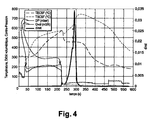
figures 2 à 4 représentant des graphiques d'évolution de paramètres de la ligne d'échappement en fonction du temps, lafigure 2 correspondant à une régénération normale, lafigure 3 représentant une régénération de transition et lafigure 4 représentant une régénération incontrôlée avec risque d'endommagement du filtre à particules.
- the
figure 1 represents a device adapted for implementing the method of the invention; - the
Figures 2 to 4 representing graphs of evolution of exhaust line parameters as a function of time, thefigure 2 corresponding to a normal regeneration, thefigure 3 representing a transitional regeneration and thefigure 4 representing an uncontrolled regeneration with risk of damage to the particulate filter.
En référence à la
Le filtre 1 est chargé progressivement en particules 3 portées avec les gaz brûlés.The filter 1 is gradually loaded into
Un calculateur 4 est relié à des capteurs permettant de collecter des données sur le filtre à particules 1. Ici, les données mesurées sont la température d'entrée des gaz en aval du filtre, la température interne Ti des gaz dans le filtre et la température de sortie des gaz du filtre Ts. Ces paramètres de températures sont collectés par trois capteurs distincts reliés au calculateur 4.A
D'autres paramètres sont également mesurés ou estimés et sont transmis au calculateur 4. De tels paramètres mesurés ou estimés sont le débit massique de gaz d'échappement provenant du moteur, la pression partielle en oxygène, la masse de suie dans le filtre à particules.Other parameters are also measured or estimated and are transmitted to the
A l'aide de ces paramètres, le calculateur génère un paramètre dinst (t)qui est représentatif de l'évolution de la régénération.Using these parameters, the computer generates a parameter of inst ( t ) which is representative of the evolution of the regeneration.
Ce paramètre dinst (t) est un rapport à chaque instant t de Vr(t) vitesse de combustion de la suie qui est la masse de suie brûlée à un instant t (par exemple des grammes par seconde ou des moles par seconde) divisé par le débit massique Qm(t) de gaz brûlés provenant du moteur et transitant par le filtre.This parameter d inst ( t ) is a ratio at each instant t of Vr (t) combustion rate of the soot which is the mass of soot burnt at a time t (for example grams per second or moles per second) divided by the mass flow Q m ( t ) of burnt gases from the engine and passing through the filter.
Plus la quantité de gaz brûlés circulait est importante et plus la quantité de chaleur pouvant être évacuée du filtre sera importante, le paramètre dinst (t) est donc minimisé par le débit massique Qm(t).The greater the amount of flue gas circulating, the greater the amount of heat that can be removed from the filter, the parameter d inst ( t ) is minimized by the mass flow Q m ( t ).
Qm(t) est généralement estimé à partir d'une mesure de la quantité d'air admise à un instant t dans le moteur et à partir de la quantité de carburant injectée dans le moteur. L'unité de Qm(t) est la masse de suie brûlée par unité de temps soit le Kg/s.Q m ( t ) is generally estimated from a measurement of the amount of air admitted at a time t into the engine and from the amount of fuel injected into the engine. The unit of Q m ( t ) is the mass of soot burned per unit time, ie Kg / s.
Ce ratio dinst (t) permet donc d'indiquer quelle est la capacité d'évacuation de chaleur hors du filtre à un instant t.This ratio d inst ( t ) thus makes it possible to indicate what is the heat evacuation capacity out of the filter at a time t.
Grâce à l'invention, ce ratio est pondéré en calculant un paramètre pondéré Dinstpond(t), défini par la fonction de dinst (t) * Gtemp (t) où Gtemp (t) est variable dans le temps (t) en fonction de la température représentative T(t), cette température représentative étant par exemple la température d'entrée des gaz du filtre Te et/ou la température Ti des gaz dans le filtre et/ou la température de sortie des gaz du filtre Ts.Thanks to the invention, this ratio is weighted by calculating a weighted parameter D inst pond ( t ), defined by the function of d inst ( t ) * Gtemp (t) where Gtemp (t) is variable in time (t) as a function of the representative temperature T (t), this representative temperature being, for example, the gas inlet temperature of the filter Te and / or the temperature Ti of the gases in the filter and / or the outlet temperature of the gases of the filter Ts.
En effet la pondération de dinst (t) à un instant t en fonction d'un paramètre de température permet de mieux visualiser l'évolution de la régénération du filtre.Indeed the weighting of d inst ( t ) at a time t as a function of a temperature parameter makes it possible to better visualize the evolution of the regeneration of the filter.
Pour ce calcul de paramètre pondéré Dinstpond(t), on utilise la formule : ![]()
où Cpex est la -capacité calorifique des gaz d'échappement exprimée en Kelvins par moles et ΔH est l'enthalpie massique de combustion des suies exprimée en joules par kelvin par mole de suie.
On utilise également la formules : 
où K est une constante.
et 
ici la masse de suie dans le filtre msuie (t) est exprimée en g et est une valeur estimée par le calculateur 4. Cette masse peut être estimée par :
- l'analyse de la quantité de carburant consommée par le moteur, et/ou
- par l'analyse de la contre pression aux bornes du filtre qui est une indication sur le colmatage du filtre par la suie et donc une estimation indirecte de la masse de suie dans le filtre.
where Cp ex is the heat capacity of exhaust gases expressed in Kelvins per mole and ΔH is the mass enthalpy of soot combustion expressed in joules per kelvin per mole of soot.
We also use the formulas:
where K is a constant.
and
here the mass of soot in the filter m soot ( t ) is expressed in g and is a value estimated by the
- analyzing the amount of fuel consumed by the engine, and / or
- by the analysis of the counter pressure at the terminals of the filter which is an indication on the clogging of the filter by the soot and therefore an indirect estimate of the mass of soot in the filter.
β est l'ordre partial de réaction de la suie et est obtenu par essais en laboratoire.β is the partial order of reaction of the soot and is obtained by laboratory tests.
k 0 est le facteur de fréquence ou facteur pré exponentiel constant. k 0 is the frequency factor or constant pre-exponential factor.
Ea est l'énergie d'activation qui est fonction de l'activité catalytique du système. Cette énergie représente la sensibilité à la températures de la réaction carbone + oxygène → CO2. E a is the activation energy which is a function of the catalytic activity of the system. This energy represents the temperature sensitivity of the carbon + oxygen → CO2 reaction.
Ea est exprimée en Joules par mole de suie. E a is expressed in Joules per mole of soot.
R est la constante des gaz parfait qui est d'environ 8.314. R is the perfect gas constant which is about 8.314.
T(t) est la température dans le filtre à l'instant t en Kelvins. Cette température T(t) est la température interne aussi appelée Ti. T ( t ) is the temperature in the filter at time t in Kelvins. This temperature T (t) is the internal temperature also called Ti.
P O2 (t) est la pression partielle de l'oxygène à l'instant t et représente la quantité d'oxygène dans les gaz brûlés 5 à l'entrée du filtre. Cette quantité est mesurée par un capteur ou estimé à partir des paramètres moteur. P O 2 (t) is the partial pressure of the oxygen at time t and represents the amount of oxygen in the flue gas at the inlet of the filter. This quantity is measured by a sensor or estimated from the motor parameters.
α est un ordre partiel de réaction pour 1'-oxygène.α is a partial reaction order for 1'-oxygen.
Pour calculer Dinstpond(t), on utilise une fonction dans laquelle Dinstpond(t) est exprimé à l'aide de dinst (t) et Gtemp (t).To calculate D inst pond ( t ), we use a function in which D inst ( t ) is expressed using d inst ( t ) and Gtemp (t).
Pour cela, Gtemp (t) est choisi parmi :
- *

- *

- *

- * Gtemp= (1 / Te2) ou ;
- * Gtemp= 1/Ti où Ti est une température interne du filtre à un instant t, ou ;
- * Gtemp= 1/Ti2 .
Dinstpond(t) peut être calculé :- soit par Dinstpond(t) = dinst (t) * Gtemp (t) ;
- soit par

- soit par la dérivée dans le temps t de dinst (t)*Gtemp(t).
- *
- *
- *
- * Gtemp = (1 / Te 2 ) or;
- * Gtemp = 1 / Ti where Ti is an internal temperature of the filter at a time t, or;
- * Gtemp = 1 / Ti 2 .
D inst pond ( t ) can be calculated:- either by inst inst ( t ) = d inst ( t ) * Gtemp (t);
- either by
- either by the derivative in time t of inst ( t ) * Gtemp (t).
Préférentiellement on exprimée Dinstpond(t) = dinst (t) * Ti (t) où Ti est la température interne du gaz dans le filtre.Preferably, we express inst inst ( t ) = d inst ( t ) * Ti (t) where Ti is the internal temperature of the gas in the filter.
En effet, ce dernier paramètre pondère est extrêmement représentatif des conditions de fonctionnement du filtre.Indeed, this last weighted parameter is extremely representative of the operating conditions of the filter.
La
Ici, dinst (t) reste égal à 0 tant que la régénération n'est pas déclenchée. Une fois la régénération déclenchée, dinst (t) augmente jusqu'à atteindre une valeur maximale de 0.0016. Cette augmentation de dinst (t) se produite sur un intervalle de temps de près de 150 seconde et cette valeur maximale de dinst (t) indique que la régénération est contrôlée. Dans le même temps la température de sortie des gaz du filtre augmente de près de 100° Celsius jusqu'à atteindre 660°C. Sur ce même intervalle de temps la pression différentielle entre l'entrée et la sortie du filtre exprimée en millibars chute, alors que le volume débit de gaz circulant dans le filtre augmente. Ce dernier point indique que le filtre se dé colmate progressivement.The
Here, d inst ( t ) remains equal to 0 until the regeneration is triggered. Once the regeneration is triggered, inst ( t ) increases until it reaches a maximum value of 0.0016. This increase of d inst ( t ) occurs over a time interval of nearly 150 seconds and this maximum value of d inst ( t ) indicates that the regeneration is controlled. At the same time, the outlet temperature of the filter gases increases by nearly 100 ° Celsius until reaching 660 ° C. Over the same time interval the differential pressure between the inlet and the outlet of the filter expressed in millibars as the volume of gas flowing through the filter increases. This last point indicates that the filter is gradually decalcified.
Tant que les valeurs de dinst (t) sont inférieures à 0.02, ce qui est ici le cas pour la
Lorsque les valeurs de dinst (t) sont supérieures à 0.02 et inférieures à 0.03, ce qui est le cas pour la
Lorsque les valeurs de dinst (t) sont supérieures à 0.03, ce qui est le cas sur la
En effet plus le paramètre dinst (t) augmente et plus la réaction se déroulant dans le filtre est violente.Indeed the more the parameter d inst ( t ) increases and the reaction taking place in the filter is violent.
Ainsi, dans le cas de la
Grâce à l'invention, il est donc possible de pondérer dinst (t) pour faciliter la lecture de la réaction de régénération et ainsi éviter de se retrouver dans levas de la
Claims (10)
- Method for controlling the regeneration of a particulate filter belonging to an exhaust line of an internal combustion engine, comprising:- the determination of particulate filter operating data, these data being at least a temperature T(t) representative of the temperature inside the filter at a time t;- a step of regenerating the filter, consisting in raising the temperature of said filter above a first temperature threshold for combustion of soot contained in said filter;- the calculation of a parameter dinst(t) that can vary over time and is representative of the amount of energy produced at a time t by the regeneration process,characterized in that it includes a step of calculating a weighted parameter Dinstwt(t), this weighted parameter being at least partly defined by the function dinst(t)×Gtemp(t) where Gtemp(t) is variable in time (t) as a function of said representative temperature T(t).
- Method according to Claim 1, characterized in that the parameter dinst(t) is obtained by the formula:

where vr(t) is the rate of combustion of soot contained in the particulate filter at the time t and Qm(t) is an estimated or measured exhaust gas mass flow rate at the time t. - Method according to either of Claims 1 and 2, characterized in that dinst(t) is obtained by the formula:

where:- msoot(t) is an estimate of the mass of soot contained in the filter at a time t;- β is a partial order of reaction for soot combustion;- k0 is a constant frequency factor;- Ea is an activation energy dependent on the catalytic activity of the system, this activation energy representing the sensitivity to the temperature of the soot combustion reaction in the filter;- R is the perfect gas constant;- PO2(t) is an oxygen partial pressure at the time t expressed as a mass percentage of oxygen in the gas contained in the filter at the time t; and- α is a partial order of reaction for oxygen. - Method according to any one of Claims 1 to 3, characterized in that Gtemp(t) is obtained by any one of the formulae belonging to the group consisting of:- Gtemp = Ts /Te where Ts and Te are gas outlet and inlet temperatures, respectively, in the particulate filter at a time t;- Gtemp = 1/Te;- Gtemp = 1/(Ts-Te);- Gtemp = (1/Te 2);- Gtemp = 1/Ti, where Ti is an internal temperature of the filter at a time t; and- Gtemp = 1/Ti 2.
- Method according to any one of Claims 1 to 4, characterized in that Dinstwt(t) = dinst(t)×Gtemp (t).
- Method according to any one of Claims 1 to 4, characterized in that


- Method according to any one of Claims 1 to 4, characterized in that Dinstwt(t) is equal to the derivative with respect to time t of dinst(t)×Gtemp(t).
- Method according to any one of Claims 1 to 7, characterized in that if the calculated weighted parameter Dinstwt(t) is:- below a first threshold value, a controlled regeneration signal is emitted; and/or- above said first threshold value and below a second threshold value, a first filter degradation risk signal is emitted; and/or- above said second threshold value an uncontrolled regeneration signal is emitted.
- Method according to any one of Claims 1 to 8, characterized in that it includes a step of stopping the regeneration, consisting in interrupting the regeneration if the calculated weighted parameter Dinstwt(t) is above a predetermined stop threshold value.
- Method according to any one of Claims 1 to 9, characterized in that values taken over time t by the calculated weighted parameter Dinstwt(t) are stored in a memory.
Applications Claiming Priority (2)
| Application Number | Priority Date | Filing Date | Title |
|---|---|---|---|
| FR0506291A FR2887291B1 (en) | 2005-06-21 | 2005-06-21 | METHOD FOR CONTROLLING REGENERATION OF A PARTICLE FILTER |
| PCT/FR2006/050615 WO2006136754A2 (en) | 2005-06-21 | 2006-06-21 | Regeneration control method for a particle filter |
Publications (2)
| Publication Number | Publication Date |
|---|---|
| EP1896710A2 EP1896710A2 (en) | 2008-03-12 |
| EP1896710B1 true EP1896710B1 (en) | 2010-11-24 |
Family
ID=36333353
Family Applications (1)
| Application Number | Title | Priority Date | Filing Date |
|---|---|---|---|
| EP06778960A Not-in-force EP1896710B1 (en) | 2005-06-21 | 2006-06-21 | Regeneration control method for a particle filter |
Country Status (7)
| Country | Link |
|---|---|
| US (1) | US8020376B2 (en) |
| EP (1) | EP1896710B1 (en) |
| JP (1) | JP4903202B2 (en) |
| AT (1) | ATE489547T1 (en) |
| DE (1) | DE602006018457D1 (en) |
| FR (1) | FR2887291B1 (en) |
| WO (1) | WO2006136754A2 (en) |
Families Citing this family (4)
| Publication number | Priority date | Publication date | Assignee | Title |
|---|---|---|---|---|
| FR2959274A1 (en) * | 2010-04-22 | 2011-10-28 | Peugeot Citroen Automobiles Sa | Method for detecting combustion risk of particles trapped in particle filter of exhaust line at outlet of i.e. diesel engine of i.e. car, has triggering operating mode of engine that reduces oxygen rate of exhaust fumes of engine |
| EP2963271B1 (en) * | 2014-06-18 | 2017-01-11 | Fiat Group Automobiles S.p.A. | System and method for estimating the quantity of particulate accumulated in the particulate filter of a diesel engine |
| KR102529510B1 (en) * | 2018-05-24 | 2023-05-04 | 현대자동차주식회사 | Method and system for calculating Soot burning rate of Gasoline Particulate Filter |
| CN111120045A (en) * | 2019-12-20 | 2020-05-08 | 潍柴动力股份有限公司 | Control method and system for DPF passive regeneration |
Family Cites Families (13)
| Publication number | Priority date | Publication date | Assignee | Title |
|---|---|---|---|---|
| JPH01127016A (en) * | 1987-11-12 | 1989-05-19 | Ngk Insulators Ltd | Combustion regenerating method for ceramic honeycomb filter |
| EP0655104B1 (en) * | 1992-08-17 | 1997-12-10 | Emitec Gesellschaft für Emissionstechnologie mbH | Process for monitoring the operation of a catalytic converter |
| DE19923299A1 (en) * | 1999-05-21 | 2000-11-23 | Bosch Gmbh Robert | Procedure for control of IC engine that comprises devices which influence exhaust of engine has with existence of certain conditions, special operating state introduced in which increased energy content of exhaust is desired. |
| JP3598961B2 (en) * | 2000-09-26 | 2004-12-08 | 日産自動車株式会社 | Exhaust gas purification device for internal combustion engine |
| FR2814498B1 (en) * | 2000-09-27 | 2003-04-11 | Renault | METHOD FOR MANAGING THE OPERATION OF A PARTICLE FILTER FOR A COMBUSTION ENGINE |
| DE50000400D1 (en) * | 2000-11-03 | 2002-09-26 | Ford Global Tech Inc | Control arrangement and method for interrupting the regeneration of a particle filter of a diesel engine |
| US6901751B2 (en) * | 2002-02-01 | 2005-06-07 | Cummins, Inc. | System for controlling particulate filter temperature |
| JP4164640B2 (en) * | 2002-04-16 | 2008-10-15 | 三菱ふそうトラック・バス株式会社 | Exhaust gas purification device for internal combustion engine |
| FR2840820B1 (en) * | 2002-06-18 | 2005-02-25 | Renault Sa | METHOD FOR REGENERATING A MOTOR VEHICLE PARTICLE FILTER AND SYSTEM FOR CONTROLLING THE REGENERATION OF SUCH A FILTER |
| JP2004293340A (en) * | 2003-03-25 | 2004-10-21 | Mitsubishi Fuso Truck & Bus Corp | Exhaust gas purifier |
| US7031827B2 (en) * | 2003-04-11 | 2006-04-18 | Ford Global Technologies, Llc | Computer algorithm to estimate particulate filter regeneration rates |
| FR2855213B1 (en) * | 2003-05-23 | 2005-07-15 | Renault Sa | METHOD AND DEVICE FOR CONTROLLING THE REGENERATION OF A PARTICLE FILTER AND MOTORIZATION ASSEMBLY COMPRISING SUCH A DEVICE |
| JP4075795B2 (en) * | 2003-12-19 | 2008-04-16 | 日産自動車株式会社 | Diesel engine exhaust aftertreatment system |
-
2005
- 2005-06-21 FR FR0506291A patent/FR2887291B1/en not_active Expired - Fee Related
-
2006
- 2006-06-21 DE DE602006018457T patent/DE602006018457D1/en active Active
- 2006-06-21 JP JP2008517559A patent/JP4903202B2/en not_active Expired - Fee Related
- 2006-06-21 WO PCT/FR2006/050615 patent/WO2006136754A2/en not_active Application Discontinuation
- 2006-06-21 EP EP06778960A patent/EP1896710B1/en not_active Not-in-force
- 2006-06-21 AT AT06778960T patent/ATE489547T1/en not_active IP Right Cessation
- 2006-06-21 US US11/993,134 patent/US8020376B2/en not_active Expired - Fee Related
Also Published As
| Publication number | Publication date |
|---|---|
| WO2006136754A3 (en) | 2007-06-21 |
| JP2008544155A (en) | 2008-12-04 |
| US20100212289A1 (en) | 2010-08-26 |
| EP1896710A2 (en) | 2008-03-12 |
| WO2006136754A2 (en) | 2006-12-28 |
| FR2887291B1 (en) | 2007-09-21 |
| DE602006018457D1 (en) | 2011-01-05 |
| ATE489547T1 (en) | 2010-12-15 |
| FR2887291A1 (en) | 2006-12-22 |
| JP4903202B2 (en) | 2012-03-28 |
| US8020376B2 (en) | 2011-09-20 |
Similar Documents
| Publication | Publication Date | Title |
|---|---|---|
| RU2622586C2 (en) | Control method of soot combustion in particulate filter of vehicle diesel engine | |
| EP1929133B1 (en) | Dpf regeneration monitoring method | |
| US5177463A (en) | Method of and apparatus for monitoring operation of a catalytic converter | |
| FR2657649A1 (en) | DEVICE FOR PURIFYING THE EXHAUST GAS OF AN INTERNAL COMBUSTION ENGINE AND METHOD OF OPERATION THEREOF. | |
| RU2484266C2 (en) | Method and device for detection of combustion in particle filter | |
| FR3029973A1 (en) | METHOD FOR MONITORING AN OXIDATION CATALYSIS DEVICE | |
| FR2872853A1 (en) | METHOD AND DEVICE FOR MANAGING A PARTICLE FILTER INSTALLED IN THE EXHAUST GAS AREA OF AN INTERNAL COMBUSTION ENGINE | |
| FR2946689A1 (en) | PREVENTING SOOT SUB-ESTIMATION IN DIESEL PARTICULATE FILTERS BY DETERMINING SENSITIVITY TO SOY BONDING | |
| FR2963388A1 (en) | METHOD FOR DIAGNOSING AN EXHAUST GAS SENSOR AND DEVICE FOR IMPLEMENTING THE METHOD | |
| FR3010445A1 (en) | EXHAUST GAS RELEASE SYSTEM OF INTERNAL COMBUSTION ENGINE AND METHOD OF RETRIEVAL | |
| EP1896710B1 (en) | Regeneration control method for a particle filter | |
| EP1281843B1 (en) | Method to determine the loading state of a particulate filter | |
| JP6365560B2 (en) | Exhaust gas purification device for internal combustion engine | |
| EP2182191B1 (en) | Method for monitoring a particle filter | |
| EP1963635A1 (en) | Method and system for combustion engine particulate filter regeneration | |
| FR2976321A1 (en) | METHOD AND DEVICE FOR DIAGNOSING AN INTERNAL COMBUSTION ENGINE PARTICLE FILTER | |
| EP2423477A1 (en) | Method for determining the physical state of a particle filter | |
| FR2955894A1 (en) | METHOD AND DEVICE FOR DETERMINING THE EXHAUST GAS TEMPERATURE IN THE EXHAUST GAS PIPE OF A HEAT ENGINE | |
| JP5912494B2 (en) | Diesel engine exhaust purification system | |
| EP1323904A1 (en) | Method for detecting uncontrolled regeneration of a particulate filter in an exhaust line of an internal combustion engine | |
| FR2855847A1 (en) | Particle filters load state determining process for internal combustion engine, involves determining pressure variation in upstream of filter in exhaust gas zone, and determining load state of filter from pressure variation | |
| EP1762718B1 (en) | Process for regeneration of a particulate filter | |
| KR101305777B1 (en) | Availability volume recognized method using learning function of Diesel Particulate Filter accumulated ash | |
| EP1413720B1 (en) | Method to determine the internal temperature of a particulate filter, method to control the regeneration of said particulate filter, control system and particulate filter thereof | |
| JP7310720B2 (en) | Catalyst state detector |
Legal Events
| Date | Code | Title | Description |
|---|---|---|---|
| PUAI | Public reference made under article 153(3) epc to a published international application that has entered the european phase |
Free format text: ORIGINAL CODE: 0009012 |
|
| 17P | Request for examination filed |
Effective date: 20080121 |
|
| AK | Designated contracting states |
Kind code of ref document: A2 Designated state(s): AT BE BG CH CY CZ DE DK EE ES FI FR GB GR HU IE IS IT LI LT LU LV MC NL PL PT RO SE SI SK TR |
|
| DAX | Request for extension of the european patent (deleted) | ||
| DAX | Request for extension of the european patent (deleted) | ||
| GRAP | Despatch of communication of intention to grant a patent |
Free format text: ORIGINAL CODE: EPIDOSNIGR1 |
|
| GRAS | Grant fee paid |
Free format text: ORIGINAL CODE: EPIDOSNIGR3 |
|
| GRAA | (expected) grant |
Free format text: ORIGINAL CODE: 0009210 |
|
| AK | Designated contracting states |
Kind code of ref document: B1 Designated state(s): AT BE BG CH CY CZ DE DK EE ES FI FR GB GR HU IE IS IT LI LT LU LV MC NL PL PT RO SE SI SK TR |
|
| REG | Reference to a national code |
Ref country code: GB Ref legal event code: FG4D Free format text: NOT ENGLISH |
|
| REG | Reference to a national code |
Ref country code: CH Ref legal event code: EP |
|
| REG | Reference to a national code |
Ref country code: IE Ref legal event code: FG4D |
|
| REF | Corresponds to: |
Ref document number: 602006018457 Country of ref document: DE Date of ref document: 20110105 Kind code of ref document: P |
|
| REG | Reference to a national code |
Ref country code: NL Ref legal event code: VDEP Effective date: 20101124 |
|
| LTIE | Lt: invalidation of european patent or patent extension |
Effective date: 20101124 |
|
| PG25 | Lapsed in a contracting state [announced via postgrant information from national office to epo] |
Ref country code: LT Free format text: LAPSE BECAUSE OF FAILURE TO SUBMIT A TRANSLATION OF THE DESCRIPTION OR TO PAY THE FEE WITHIN THE PRESCRIBED TIME-LIMIT Effective date: 20101124 |
|
| PG25 | Lapsed in a contracting state [announced via postgrant information from national office to epo] |
Ref country code: PT Free format text: LAPSE BECAUSE OF FAILURE TO SUBMIT A TRANSLATION OF THE DESCRIPTION OR TO PAY THE FEE WITHIN THE PRESCRIBED TIME-LIMIT Effective date: 20110324 Ref country code: SE Free format text: LAPSE BECAUSE OF FAILURE TO SUBMIT A TRANSLATION OF THE DESCRIPTION OR TO PAY THE FEE WITHIN THE PRESCRIBED TIME-LIMIT Effective date: 20101124 Ref country code: CY Free format text: LAPSE BECAUSE OF FAILURE TO SUBMIT A TRANSLATION OF THE DESCRIPTION OR TO PAY THE FEE WITHIN THE PRESCRIBED TIME-LIMIT Effective date: 20101124 Ref country code: SI Free format text: LAPSE BECAUSE OF FAILURE TO SUBMIT A TRANSLATION OF THE DESCRIPTION OR TO PAY THE FEE WITHIN THE PRESCRIBED TIME-LIMIT Effective date: 20101124 Ref country code: NL Free format text: LAPSE BECAUSE OF FAILURE TO SUBMIT A TRANSLATION OF THE DESCRIPTION OR TO PAY THE FEE WITHIN THE PRESCRIBED TIME-LIMIT Effective date: 20101124 Ref country code: BG Free format text: LAPSE BECAUSE OF FAILURE TO SUBMIT A TRANSLATION OF THE DESCRIPTION OR TO PAY THE FEE WITHIN THE PRESCRIBED TIME-LIMIT Effective date: 20110224 Ref country code: FI Free format text: LAPSE BECAUSE OF FAILURE TO SUBMIT A TRANSLATION OF THE DESCRIPTION OR TO PAY THE FEE WITHIN THE PRESCRIBED TIME-LIMIT Effective date: 20101124 Ref country code: AT Free format text: LAPSE BECAUSE OF FAILURE TO SUBMIT A TRANSLATION OF THE DESCRIPTION OR TO PAY THE FEE WITHIN THE PRESCRIBED TIME-LIMIT Effective date: 20101124 Ref country code: IS Free format text: LAPSE BECAUSE OF FAILURE TO SUBMIT A TRANSLATION OF THE DESCRIPTION OR TO PAY THE FEE WITHIN THE PRESCRIBED TIME-LIMIT Effective date: 20110324 Ref country code: LV Free format text: LAPSE BECAUSE OF FAILURE TO SUBMIT A TRANSLATION OF THE DESCRIPTION OR TO PAY THE FEE WITHIN THE PRESCRIBED TIME-LIMIT Effective date: 20101124 |
|
| REG | Reference to a national code |
Ref country code: IE Ref legal event code: FD4D |
|
| PG25 | Lapsed in a contracting state [announced via postgrant information from national office to epo] |
Ref country code: GR Free format text: LAPSE BECAUSE OF FAILURE TO SUBMIT A TRANSLATION OF THE DESCRIPTION OR TO PAY THE FEE WITHIN THE PRESCRIBED TIME-LIMIT Effective date: 20110225 |
|
| PG25 | Lapsed in a contracting state [announced via postgrant information from national office to epo] |
Ref country code: EE Free format text: LAPSE BECAUSE OF FAILURE TO SUBMIT A TRANSLATION OF THE DESCRIPTION OR TO PAY THE FEE WITHIN THE PRESCRIBED TIME-LIMIT Effective date: 20101124 Ref country code: CZ Free format text: LAPSE BECAUSE OF FAILURE TO SUBMIT A TRANSLATION OF THE DESCRIPTION OR TO PAY THE FEE WITHIN THE PRESCRIBED TIME-LIMIT Effective date: 20101124 Ref country code: ES Free format text: LAPSE BECAUSE OF FAILURE TO SUBMIT A TRANSLATION OF THE DESCRIPTION OR TO PAY THE FEE WITHIN THE PRESCRIBED TIME-LIMIT Effective date: 20110307 Ref country code: IE Free format text: LAPSE BECAUSE OF FAILURE TO SUBMIT A TRANSLATION OF THE DESCRIPTION OR TO PAY THE FEE WITHIN THE PRESCRIBED TIME-LIMIT Effective date: 20101124 |
|
| PG25 | Lapsed in a contracting state [announced via postgrant information from national office to epo] |
Ref country code: SK Free format text: LAPSE BECAUSE OF FAILURE TO SUBMIT A TRANSLATION OF THE DESCRIPTION OR TO PAY THE FEE WITHIN THE PRESCRIBED TIME-LIMIT Effective date: 20101124 Ref country code: RO Free format text: LAPSE BECAUSE OF FAILURE TO SUBMIT A TRANSLATION OF THE DESCRIPTION OR TO PAY THE FEE WITHIN THE PRESCRIBED TIME-LIMIT Effective date: 20101124 Ref country code: DK Free format text: LAPSE BECAUSE OF FAILURE TO SUBMIT A TRANSLATION OF THE DESCRIPTION OR TO PAY THE FEE WITHIN THE PRESCRIBED TIME-LIMIT Effective date: 20101124 Ref country code: PL Free format text: LAPSE BECAUSE OF FAILURE TO SUBMIT A TRANSLATION OF THE DESCRIPTION OR TO PAY THE FEE WITHIN THE PRESCRIBED TIME-LIMIT Effective date: 20101124 |
|
| PLBE | No opposition filed within time limit |
Free format text: ORIGINAL CODE: 0009261 |
|
| STAA | Information on the status of an ep patent application or granted ep patent |
Free format text: STATUS: NO OPPOSITION FILED WITHIN TIME LIMIT |
|
| 26N | No opposition filed |
Effective date: 20110825 |
|
| REG | Reference to a national code |
Ref country code: DE Ref legal event code: R097 Ref document number: 602006018457 Country of ref document: DE Effective date: 20110825 |
|
| PG25 | Lapsed in a contracting state [announced via postgrant information from national office to epo] |
Ref country code: IT Free format text: LAPSE BECAUSE OF FAILURE TO SUBMIT A TRANSLATION OF THE DESCRIPTION OR TO PAY THE FEE WITHIN THE PRESCRIBED TIME-LIMIT Effective date: 20101124 |
|
| BERE | Be: lapsed |
Owner name: RENAULT SAS Effective date: 20110630 |
|
| REG | Reference to a national code |
Ref country code: CH Ref legal event code: PL |
|
| PG25 | Lapsed in a contracting state [announced via postgrant information from national office to epo] |
Ref country code: BE Free format text: LAPSE BECAUSE OF NON-PAYMENT OF DUE FEES Effective date: 20110630 |
|
| PG25 | Lapsed in a contracting state [announced via postgrant information from national office to epo] |
Ref country code: LI Free format text: LAPSE BECAUSE OF NON-PAYMENT OF DUE FEES Effective date: 20110630 Ref country code: CH Free format text: LAPSE BECAUSE OF NON-PAYMENT OF DUE FEES Effective date: 20110630 |
|
| PG25 | Lapsed in a contracting state [announced via postgrant information from national office to epo] |
Ref country code: MC Free format text: LAPSE BECAUSE OF NON-PAYMENT OF DUE FEES Effective date: 20110630 |
|
| PG25 | Lapsed in a contracting state [announced via postgrant information from national office to epo] |
Ref country code: LU Free format text: LAPSE BECAUSE OF NON-PAYMENT OF DUE FEES Effective date: 20110621 |
|
| PG25 | Lapsed in a contracting state [announced via postgrant information from national office to epo] |
Ref country code: TR Free format text: LAPSE BECAUSE OF FAILURE TO SUBMIT A TRANSLATION OF THE DESCRIPTION OR TO PAY THE FEE WITHIN THE PRESCRIBED TIME-LIMIT Effective date: 20101124 |
|
| PG25 | Lapsed in a contracting state [announced via postgrant information from national office to epo] |
Ref country code: HU Free format text: LAPSE BECAUSE OF FAILURE TO SUBMIT A TRANSLATION OF THE DESCRIPTION OR TO PAY THE FEE WITHIN THE PRESCRIBED TIME-LIMIT Effective date: 20101124 |
|
| REG | Reference to a national code |
Ref country code: FR Ref legal event code: PLFP Year of fee payment: 10 |
|
| REG | Reference to a national code |
Ref country code: FR Ref legal event code: PLFP Year of fee payment: 11 |
|
| REG | Reference to a national code |
Ref country code: FR Ref legal event code: PLFP Year of fee payment: 12 |
|
| PGFP | Annual fee paid to national office [announced via postgrant information from national office to epo] |
Ref country code: FR Payment date: 20170621 Year of fee payment: 12 Ref country code: DE Payment date: 20170621 Year of fee payment: 12 Ref country code: GB Payment date: 20170620 Year of fee payment: 12 |
|
| REG | Reference to a national code |
Ref country code: DE Ref legal event code: R119 Ref document number: 602006018457 Country of ref document: DE |
|
| GBPC | Gb: european patent ceased through non-payment of renewal fee |
Effective date: 20180621 |
|
| PG25 | Lapsed in a contracting state [announced via postgrant information from national office to epo] |
Ref country code: DE Free format text: LAPSE BECAUSE OF NON-PAYMENT OF DUE FEES Effective date: 20190101 Ref country code: FR Free format text: LAPSE BECAUSE OF NON-PAYMENT OF DUE FEES Effective date: 20180630 Ref country code: GB Free format text: LAPSE BECAUSE OF NON-PAYMENT OF DUE FEES Effective date: 20180621 |