EP1895639A2 - Permanent magnet and permanent magnet rotating machine - Google Patents
Permanent magnet and permanent magnet rotating machine Download PDFInfo
- Publication number
- EP1895639A2 EP1895639A2 EP07253431A EP07253431A EP1895639A2 EP 1895639 A2 EP1895639 A2 EP 1895639A2 EP 07253431 A EP07253431 A EP 07253431A EP 07253431 A EP07253431 A EP 07253431A EP 1895639 A2 EP1895639 A2 EP 1895639A2
- Authority
- EP
- European Patent Office
- Prior art keywords
- magnet
- permanent magnet
- central region
- top surface
- arcuate
- Prior art date
- Legal status (The legal status is an assumption and is not a legal conclusion. Google has not performed a legal analysis and makes no representation as to the accuracy of the status listed.)
- Granted
Links
Images




Classifications
-
- H—ELECTRICITY
- H02—GENERATION; CONVERSION OR DISTRIBUTION OF ELECTRIC POWER
- H02K—DYNAMO-ELECTRIC MACHINES
- H02K1/00—Details of the magnetic circuit
- H02K1/06—Details of the magnetic circuit characterised by the shape, form or construction
- H02K1/22—Rotating parts of the magnetic circuit
- H02K1/27—Rotor cores with permanent magnets
-
- H—ELECTRICITY
- H02—GENERATION; CONVERSION OR DISTRIBUTION OF ELECTRIC POWER
- H02K—DYNAMO-ELECTRIC MACHINES
- H02K1/00—Details of the magnetic circuit
- H02K1/06—Details of the magnetic circuit characterised by the shape, form or construction
- H02K1/22—Rotating parts of the magnetic circuit
- H02K1/27—Rotor cores with permanent magnets
- H02K1/2706—Inner rotors
- H02K1/272—Inner rotors the magnetisation axis of the magnets being perpendicular to the rotor axis
- H02K1/274—Inner rotors the magnetisation axis of the magnets being perpendicular to the rotor axis the rotor consisting of two or more circumferentially positioned magnets
- H02K1/2753—Inner rotors the magnetisation axis of the magnets being perpendicular to the rotor axis the rotor consisting of two or more circumferentially positioned magnets the rotor consisting of magnets or groups of magnets arranged with alternating polarity
- H02K1/278—Surface mounted magnets; Inset magnets
- H02K1/2781—Magnets shaped to vary the mechanical air gap between the magnets and the stator
-
- H—ELECTRICITY
- H01—ELECTRIC ELEMENTS
- H01F—MAGNETS; INDUCTANCES; TRANSFORMERS; SELECTION OF MATERIALS FOR THEIR MAGNETIC PROPERTIES
- H01F7/00—Magnets
- H01F7/02—Permanent magnets [PM]
Definitions
- This invention relates to a D-shaped permanent magnet, and a synchronous permanent magnet rotating machine comprising the same, such as a servo motor, DG brushless motor or power generator.
- PM rotating machines are commonly used as control motors, typically servo motors.
- AC servo motors for example, a permanent magnet rotating machine with a radial air gap as illustrated in FIG. 7 is used.
- This PM rotating machine comprises a rotor 3 including a rotor core 1 and a plurality of D-shaped permanent magnet segments 2 attached to the surface of the core, and a stator 13 surrounding the rotor 3 to define a gap therebetween and including a stator core 11 having a plurality of slots and coils 12 wound on teeth and received in the slots.
- the number of (permanent magnet) poles is six (6)
- the number of teeth is nine (9)
- the arrow associated with a permanent magnet segment indicates a direction of magnetization thereof.
- the coils are wound on teeth as a concentrated winding and connected in Y connection of three phases: U, V and W phases as shown in FIG. 8.
- U, V and W phases as shown in FIG. 8.
- the solid circle of a coil denotes that the coil winding direction is forward and the crossing (X) of a coil denotes that the coil winding direction is backward, with respect to the plane of paper.
- the torque In AC servo motors and similar motors requiring high precision torque control, the torque must have less ripples. Accordingly, it is undesired that when the permanent magnets rotate, the alignment of stator slots and the permanent magnets causes cogging torque to develop due to variations of the magnetic flux distribution across the gap (i.e., torque without current flowing across the coil) or torque ripples to occur when driven by current flowing across the coil. The torque ripples exacerbate controllability and additionally, cause noise.
- the cogging torque may be reduced by configuring a permanent magnet segment to a cross-sectional D shape that tapers from the center toward transverse ends (edges) and has an off-centered arcuate portion as shown in FIG. 9 i.e. with a convex arc radius smaller than that of the notional great circle to which it is tangent. With this configuration, the end portion of a permanent magnet segment which is a magnetic pole switch area developing a noticeable variation of magnetic flux distribution produces a smoothened magnetic flux distribution, reducing the cogging torque.
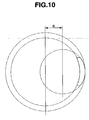
- the cogging torque may also be reduced by configuring a permanent magnet segment to a cross-sectional C shape that includes an off-centered arcuate portion as shown in FIG. 10.
- the D-shaped magnet is more effective for reducing cogging torque even if slightly off-centered, because the thickness difference between the end portions and central portion is greater.
- off-centered magnets have a reduced volume and thus lead to a reduction of drive torque, a proportion of torque reduction is smaller with the magnet of D shape which can reduce cogging torque with a less off-centering. Then the magnet of D shape is superior to C shape.
- An off-centered D-shaped magnet as shown in FIG. 9 has end portions which are very thin and susceptible to demagnetization. Now the reason why a thin gage magnet end portion is susceptible to demagnetization is described.
- the magnitude of demagnetization of a permanent magnet is determined by the magnitude of a coercive force and the magnitude of a diamagnetic field at the service temperature.
- the demagnetization susceptibility increases as the coercive force is lower and as the diamagnetic field is greater.
- the diamagnetic field is the sum of a self diamagnetic field created by magnetization of a permanent magnet and a reverse magnetic field from the exterior. To the permanent magnet end portion is applied a high diamagnetic field from the stator.
- the self diamagnetic field increases as the thickness of the permanent magnet in the magnetization direction is reduced.
- JP-A 2006-60920 Reference should be made to JP-A 2006-60920 .
- An aim herein is to provide new and useful permanent magnets which have relatively low cogging torque and are relatively unsusceptible to demagnetization when used in a rotating machine; and a permanent magnet rotating machine comprising the same, having high output and high precision control capabilities.
- the invention provides a permanent magnet having a D-shaped cross section including a generally arcuate top surface, a flat bottom surface, and side surfaces, said generally arcuate top surface including a central region with an apex and transversely opposed end regions.
- the central region of the magnet top surface delineates a contour which is coincident with a phantom small circle off-centered from said great circle and having a smaller diameter than said great circle, and each of the transversely opposed end regions of the magnet top surface is positioned outside the intersection between said small circle and the magnet side surface and inside the intersection between said great circle and the magnet side surface.
- the invention provides a permanent magnet body suitable for the use as described, i.e. as one in a circumferential array of such permanent magnet bodies in a rotary electric machine (motor or generator).
- magnet bodies are arranged with a longitudinal direction thereof parallel to an axial direction of the machine and a transverse direction thereof arranged circumferentially, a bottom surface of the magnet body facing the axis of the rotor in which the magnet bodies are comprised and the top surface facing outwardly towards the opposing stator.
- the transverse extremities are respectively leading and trailing relative to the operational rotation direction.
- the magnet body proposed herein has, as in previous proposals, a central region with (in transverse cross-section) an arcuately convex top surface and the body tapers in thickness (meaning the thickness from top to bottom, corresponding to the radial direction in the assembled machine) towards the transverse extremities or edge regions.
- the bottom surface is flat, corresponding to the preferred D-shaped cross-section mentioned above.
- the top surface of the magnet body at an edge region thereof - at least the trailing edge region, and preferably both - is angled (in the transverse cross-section) outwardly relative to the arcuate part corresponding to the central region.
- the corresponding edge region of the magnet body is thicker than if the top surface continued to the edge of the body as a continuation of the arc of the central region.
- the arc of the central region is a circular arc segment.
- the line of the top surface may extend substantially perpendicularly to the thickness direction (i.e. the thickness direction at the transverse centre of the body), or it may extend at some angle between that perpendicular direction and said notional continuation of the arc of the central region surface.
- the line of the top surface may be curved or straight. Desirably it is straight.
- the transverse cross-sectional shape is symmetrical to either side of the longitudinal axis.
- the edge regions preferably have transversely-directed side surfaces.
- a machine rotor which is an aspect of the invention comprises an array of a plurality of the magnet bodies distributed circumferentially.
- the above-mentioned great circle is defined to touch the radially outermost parts of the central regions of the magnet bodies. It is desirable that the outermost transverse extremities of the mentioned edge regions do not extend outwardly of the great circle; desirably they lie within it as described above.
- the generally arcuate top surface includes an arcuate central region and transversely opposed linear end regions which extend from the ends of the central region to the side surfaces of the magnet and parallel to the flat bottom surface of the magnet.
- the generally arcuate top surface includes an arcuate central region and transversely opposed linear oblique end regions which extend from the ends of the central region to the side surfaces of the magnet, and_an extension of the linear oblique end region toward the arcuate central region passes the apex of the arcuate central region.
- the invention provides a permanent magnet rotating machine comprising the permanent magnet defined above.
- D-shaped permanent magnets as proposed herein have a low susceptibility to demagnetization, and can reduce cogging torque and increase drive torque. They are useful in the performance improvement and size reduction of AC servo permanent magnet motors and DC brushless permanent magnet motors. These characteristics are of great worth in the industry.
- an aspect herein relates to a permanent magnet having a D-shaped cross section including a generally arcuate top surface, a flat bottom surface, and side surfaces, said generally arcuate top surface including a central region with an apex and transversely opposed end regions, wherein provided that a plurality of permanent magnets are circumferentially arranged so that a phantom great circle circumscribes the apexes on the arcuate top surfaces of the magnets, the central region delineates a contour which is coincident with a phantom small circle off-centered from said great circle and having a smaller diameter than said great circle, and each of the transversely opposed end regions is positioned outside the intersection between said small circle and the magnet side surface and inside the intersection between said great circle and the magnet side surface.
- a rotating machine comprises a rotor which has mounted thereon a plurality of permanent magnets, each magnet has an arcuate central portion which is off-centered relative to the great circle for reducing cogging and transversely opposed end portions which are kept relatively thick although they are otherwise designed extremely thin for demagnetization purpose.
- the machine produces smooth rotation with minimized cogging torque and no torque variations. The drawback of off-centered permanent magnets that magnet end portions are susceptible to demagnetization is mitigated.
- the invention is embodied as a D-shaped permanent magnet.
- the magnet 20 has a uniform D-shaped cross section including a generally arcuate top surface 22, a flat bottom surface 24, and side surfaces 26 and 28.
- the generally arcuate top surface 22 includes a central region with an apex P and transversely opposed end regions 22a, 22b.
- a plurality of D-shaped permanent magnets are circumferentially arranged as shown in FIG. 7 (six magnets in FIG. 7) so that a phantom great circle S having a center and a diameter circumscribes the apexes P on the arcuate top surfaces 22 of the magnets.
- the central region of the top surface 22 of the magnet delineates a contour which is coincident with a phantom small circle T having a center shifted from the center of the great circle S and a diameter smaller than the diameter of the great circle S.
- Each of the transversely opposed end regions 22a, 22b is positioned outside the intersection between the small circle T and the side surface 26, 28 of the magnet and inside the intersection between the great circle S and an outward extension of the side surface 26, 28 of the magnet.
- the D-shaped permanent magnet includes an arcuate central portion having a thickness Tc and transversely opposed end portions having a thickness Te.
- Te1 is a distance from the bottom surface 24 to the intersection between the small circle T (central arcuate region) and the side surface 26, and Te2 is a distance from the bottom surface 24 to the intersection between the great circle S and an extension of the side surface 26, they satisfy the relationship: Te1 ⁇ Te ⁇ Te2. If Te ⁇ Te1, then substantial demagnetization occurs. If Te > Te2, then substantial cogging occurs.
- D is a difference between a radius "s" of phantom great circle S and a radius "t" of phantom small circle T, that is, an off-centered distance.
- the ratio t/s is preferably from 0.3 to 0.8, and more preferably from 0.4 to 0.7.
- the generally arcuate top surface 22 includes an arcuate central region and linear transversely opposed end regions 22a, 22b which extend from the ends of the central region to the side surfaces 26, 28 of the magnet 20 and parallel to the flat bottom surface 24 of the magnet 20.
- the transversely opposed end portions have a constant thickness Te.
- the generally arcuate top surface 22 includes an arcuate central region and linear transversely opposed end regions 22a, 22b which obliquely extend from the ends of the central region to the side surfaces 26, 28 of the magnet 20, and an extension of the linear end region toward the arcuate central region passes the apex P of the arcuate central region.
- Te3 is a thickness at an intersection Q between a straight line connecting the opposed end regions 22a, 22b with the apex P and the phantom small circle T. The inclination from 22a, 22b to the intersection Q is a straight line.
- the D-shaped magnet may be obtained by preparing a preselected alloy by a powder metallurgy or strip casting technique, pulverizing the alloy, compacting the powder in a magnetic field by means of a die, and sintering the compact.
- the material may be machined to a desired shape prior to or after the sintering step using a machining tool, grinding tool or the like. In this way, an elongated magnet segment of D-shaped cross section is obtained as shown in FIGS. 3 and 6.
- the magnet thus obtained may be surface processed by plating or coating.
- a permanent magnet rotating machine is illustrated in FIG. 7 as comprising a rotor 3 including a rotor core 1 and a plurality of D-shaped permanent magnet segments 2 attached to the surface of the core, and a stator 13 surrounding the rotor 3 to define a gap therebetween and including a stator core 11 having a plurality of slots and coils 12 received in the slots.
- the number of magnet segments used in the machine is not particularly limited. Typically an even number of at most 100 magnet segments, and preferably 4 to 36 magnet segments are circumferentially arranged so that the polarity is alternately opposite in the circumferential direction.
- One exemplary permanent magnet rotating machine comprises a rotor including a rotor core yoke and a plurality of permanent magnet segments arranged on the side surface of the rotor core yoke at predetermined intervals such that the polarity is alternately opposite in a circumferential direction of the rotor core yoke, and a stator surrounding the rotor to define a gap therebetween and including a stator core yoke, salient magnetic poles arranged on the stator core yoke at predetermined intervals in a circumferential direction thereof and opposed to said permanent magnet segments, and armature windings concentratedly wound on the salient magnetic poles and connected in three-phase connection.
- the magnet material used herein is not particularly limited. Depending on a particular application, a choice may be made among alnico, ferrite, and rare earth magnets including Nd and Sm base magnets.
- the green compact was sintered in an argon gas at 1,090°C for 1 hour and subsequently, heat treated at 580°C for 1 hour.
- the sintered body as heat treated was a parallelepiped block.
- the block was ground into a D-shaped permanent magnet.
- a motor was constructed as a 6 pole, 9 slot motor of the structure shown in FIG. 7.
- the rotor and stator had an axial length of 70 mm.
- the rotor had a diameter of 45 mm.
- the coils were connected as shown in FIG. 8, with the number of windings being 15 turns per tooth.
- D-shaped permanent magnets shown in FIG. 9 were used.
- the magnet of FIG. 9 has a width W of 15 mm.
- the phantom great circle S has a diameter of 45 mm
- the phantom small circle T has a diameter of 31 mm
- the off-center distance D i.e., the distance between the center of the great circle and the center of the small circle
- the magnet includes a central portion having a thickness Tc of 3 mm and end portions having a thickness Te1 of 1 mm.
- the cogging torque of the motor was measured, and the drive torque of the motor measured by conducting sine-wave three-phase current having a RMS value of 150 A (1/3 current flow per coil because the coils of respective phases are parallel as shown in FIG. 8) as the input at room temperature (RT).
- Table 1 tabulates the values of cogging torque, drive torque and percent demagnetization.
- the cogging torque is a difference between maximum and minimum of pulsating waves.
- the drive torque is an average.
- the motor showed a cogging torque which is about 0.44% of the drive torque, indicating minimal cogging torque. Since the control motor is generally designed to achieve a cogging torque of 1% or below, the result is fully satisfactory. However, a demagnetization was observed at 140°C, indicating that the motor could not be used in an environment at 140°C.
- Example 1 a motor was evaluated in which a rotor having D-shaped permanent magnets shown in FIGS. 1 to 3 was assembled with a stator as in Comparative Example 1.
- the test items and driving conditions are the same as in Comparative Example 1.
- the magnet of FIG. 1 has a width W of 15 mm and an off-center distance D of 8 mm.
- the magnet includes a central portion having a thickness Tc of 3 mm and end portions having a thickness Te of 1.5 mm (FIG. 2).
- the distance Te1 from the bottom surface 24 to the intersection between the small circle T and the side surface was 0.9 mm
- Te2 from the bottom surface 24 to the intersection between the great circle S and the side surface was 1.7 mm.
- Table 1 tabulates the values of cogging torque, drive torque and percent demagnetization.
- the cogging torque is less than that of Comparative Example-1, and the drive torque is greater than that of Comparative Example 1. No demagnetization was observed at 140°C.
- Example 2 a motor was evaluated in which a rotor having D-shaped permanent magnets shown in FIGS. 4 to 6 was assembled with a stator as in Comparative Example 1.
- the test items and driving conditions are the same as in Comparative Example 1.
- the magnet of FIG. 4 has a width W of 15 mm and an off-center distance D of 8 mm.
- the magnet has a central portion thickness Tc of 3 mm, an edge thickness Te of 1.5 mm, and a thickness Te3 of 2.2 mm.
- Table 1 tabulates the values of cogging torque, drive torque and percent demagnetization.
- the cogging torque is slightly more than that of Comparative Example 1, but clears the target of 1% of the drive torque or below.
- the drive torque is greater than in Comparative Example 1 and even in Example 1. No demagnetization was observed at 140°C.
- Table 1 Cogging torque (Nm) Drive torque (Nm) Demagnetization (%) Example 1 0.025 9.5 0 0 Example 2 0.050 9.6 0 Comparative Example 1 0.040 9.1 4
Landscapes
- Engineering & Computer Science (AREA)
- Power Engineering (AREA)
- Physics & Mathematics (AREA)
- Electromagnetism (AREA)
- Permanent Field Magnets Of Synchronous Machinery (AREA)
Abstract
Description
- This invention relates to a D-shaped permanent magnet, and a synchronous permanent magnet rotating machine comprising the same, such as a servo motor, DG brushless motor or power generator.
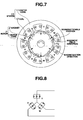
- Due to high efficiency and precise control abilities, permanent magnet (PM) rotating machines are commonly used as control motors, typically servo motors. In AC servo motors, for example, a permanent magnet rotating machine with a radial air gap as illustrated in FIG. 7 is used. This PM rotating machine comprises a
rotor 3 including arotor core 1 and a plurality of D-shapedpermanent magnet segments 2 attached to the surface of the core, and astator 13 surrounding therotor 3 to define a gap therebetween and including astator core 11 having a plurality of slots andcoils 12 wound on teeth and received in the slots. In the PM rotating machine illustrated in FIG. 7, the number of (permanent magnet) poles is six (6), the number of teeth is nine (9), and the arrow associated with a permanent magnet segment indicates a direction of magnetization thereof. With regard to the permanent magnet segments, magnetic orientation is effected in a parallel magnetic field so that a direction of easy magnetization is parallel to the center axis of the magnet segment. The coils are wound on teeth as a concentrated winding and connected in Y connection of three phases: U, V and W phases as shown in FIG. 8. In FIG. 7, the solid circle of a coil denotes that the coil winding direction is forward and the crossing (X) of a coil denotes that the coil winding direction is backward, with respect to the plane of paper. - When electric current flows across coils, magnetic fields are developed in the directions of broad arrows depicted in the stator core region, so that the rotor is rotated counterclockwise. Then, the trailing edge of a permanent magnet segment in the rotating direction (a circled area of
segment 2 in FIG. 7) is in a situation susceptible to demagnetization because the magnetic field is in an opposite direction to the magnetization of the permanent magnet segment. Commonly used permanent magnet materials include ferrite magnets such as barium ferrite and strontium ferrite and rare earth magnets such Sm-Co and Nd-Fe-B magnets. Of these, the rare earth magnets now find a dramatically increasing use as the high-performance magnet. - In AC servo motors and similar motors requiring high precision torque control, the torque must have less ripples. Accordingly, it is undesired that when the permanent magnets rotate, the alignment of stator slots and the permanent magnets causes cogging torque to develop due to variations of the magnetic flux distribution across the gap (i.e., torque without current flowing across the coil) or torque ripples to occur when driven by current flowing across the coil. The torque ripples exacerbate controllability and additionally, cause noise.
- The cogging torque may be reduced by configuring a permanent magnet segment to a cross-sectional D shape that tapers from the center toward transverse ends (edges) and has an off-centered arcuate portion as shown in FIG. 9 i.e. with a convex arc radius smaller than that of the notional great circle to which it is tangent. With this configuration, the end portion of a permanent magnet segment which is a magnetic pole switch area developing a noticeable variation of magnetic flux distribution produces a smoothened magnetic flux distribution, reducing the cogging torque. The cogging torque may also be reduced by configuring a permanent magnet segment to a cross-sectional C shape that includes an off-centered arcuate portion as shown in FIG. 10. The D-shaped magnet is more effective for reducing cogging torque even if slightly off-centered, because the thickness difference between the end portions and central portion is greater. Although off-centered magnets have a reduced volume and thus lead to a reduction of drive torque, a proportion of torque reduction is smaller with the magnet of D shape which can reduce cogging torque with a less off-centering. Then the magnet of D shape is superior to C shape.
- An off-centered D-shaped magnet as shown in FIG. 9 has end portions which are very thin and susceptible to demagnetization. Now the reason why a thin gage magnet end portion is susceptible to demagnetization is described. The magnitude of demagnetization of a permanent magnet is determined by the magnitude of a coercive force and the magnitude of a diamagnetic field at the service temperature. The demagnetization susceptibility increases as the coercive force is lower and as the diamagnetic field is greater. The diamagnetic field is the sum of a self diamagnetic field created by magnetization of a permanent magnet and a reverse magnetic field from the exterior. To the permanent magnet end portion is applied a high diamagnetic field from the stator. The self diamagnetic field increases as the thickness of the permanent magnet in the magnetization direction is reduced.
- Once the magnet is demagnetized, there arise problems that the drive torque is reduced and the cogging torque is increased due to a locally uneven magnetic field.
- Reference should be made to
JP-A 2006-60920 - An aim herein is to provide new and useful permanent magnets which have relatively low cogging torque and are relatively unsusceptible to demagnetization when used in a rotating machine; and a permanent magnet rotating machine comprising the same, having high output and high precision control capabilities.
- Making efforts in further improving a rotating machine comprising off-centered magnets and featuring reduced cogging torque, the inventors have reached a rotating machine free of torque variations and unsusceptible to demagnetization.
- In one aspect, the invention provides a permanent magnet having a D-shaped cross section including a generally arcuate top surface, a flat bottom surface, and side surfaces, said generally arcuate top surface including a central region with an apex and transversely opposed end regions. When a plurality of the permanent magnets are circumferentially arranged so that a phantom great circle circumscribes the apexes on the arcuate top surfaces of the magnets, the central region of the magnet top surface delineates a contour which is coincident with a phantom small circle off-centered from said great circle and having a smaller diameter than said great circle, and each of the transversely opposed end regions of the magnet top surface is positioned outside the intersection between said small circle and the magnet side surface and inside the intersection between said great circle and the magnet side surface.
- In an alternative aspect, the invention provides a permanent magnet body suitable for the use as described, i.e. as one in a circumferential array of such permanent magnet bodies in a rotary electric machine (motor or generator). In the well-known manner, such magnet bodies are arranged with a longitudinal direction thereof parallel to an axial direction of the machine and a transverse direction thereof arranged circumferentially, a bottom surface of the magnet body facing the axis of the rotor in which the magnet bodies are comprised and the top surface facing outwardly towards the opposing stator. The transverse extremities (edge regions, or "end portions" as referred to elsewhere herein) are respectively leading and trailing relative to the operational rotation direction. The magnet body proposed herein has, as in previous proposals, a central region with (in transverse cross-section) an arcuately convex top surface and the body tapers in thickness (meaning the thickness from top to bottom, corresponding to the radial direction in the assembled machine) towards the transverse extremities or edge regions. Preferably the bottom surface is flat, corresponding to the preferred D-shaped cross-section mentioned above.
- According to our proposal in this aspect, the top surface of the magnet body at an edge region thereof - at least the trailing edge region, and preferably both - is angled (in the transverse cross-section) outwardly relative to the arcuate part corresponding to the central region. As a result of this relatively outwardly angled part of the top surface, the corresponding edge region of the magnet body is thicker than if the top surface continued to the edge of the body as a continuation of the arc of the central region. Desirably the arc of the central region is a circular arc segment.
- At said edge region(s) the line of the top surface (in the transverse cross-section) may extend substantially perpendicularly to the thickness direction (i.e. the thickness direction at the transverse centre of the body), or it may extend at some angle between that perpendicular direction and said notional continuation of the arc of the central region surface.
- At said edge region(s) the line of the top surface (in transverse cross-section) may be curved or straight. Desirably it is straight. Usually the transverse cross-sectional shape is symmetrical to either side of the longitudinal axis.
- The edge regions preferably have transversely-directed side surfaces.
- A machine rotor which is an aspect of the invention comprises an array of a plurality of the magnet bodies distributed circumferentially. In the array, the above-mentioned great circle is defined to touch the radially outermost parts of the central regions of the magnet bodies. It is desirable that the outermost transverse extremities of the mentioned edge regions do not extend outwardly of the great circle; desirably they lie within it as described above.
- In a preferred embodiment, the generally arcuate top surface includes an arcuate central region and transversely opposed linear end regions which extend from the ends of the central region to the side surfaces of the magnet and parallel to the flat bottom surface of the magnet.
- In another preferred embodiment, the generally arcuate top surface includes an arcuate central region and transversely opposed linear oblique end regions which extend from the ends of the central region to the side surfaces of the magnet, and_an extension of the linear oblique end region toward the arcuate central region passes the apex of the arcuate central region.
- In another aspect, the invention provides a permanent magnet rotating machine comprising the permanent magnet defined above.
- We find that D-shaped permanent magnets as proposed herein have a low susceptibility to demagnetization, and can reduce cogging torque and increase drive torque. They are useful in the performance improvement and size reduction of AC servo permanent magnet motors and DC brushless permanent magnet motors. These characteristics are of great worth in the industry.
-
- FIG. 1 is a cross-sectional view of a permanent magnet in one embodiment of the invention.
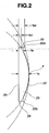
- FIG. 2 is an enlarged view of the magnet of FIG. 1.
- FIG. 3 is a perspective view of the magnet of FIG. 1.
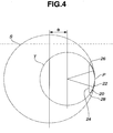
- FIG. 4 is a cross-sectional view of a permanent magnet in another embodiment of the invention.
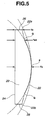
- FIG. 5 is an enlarged view of the magnet of FIG. 4.
- FIG. 6 is a perspective view of the magnet of FIG. 4.
- FIG. 7 is a cross-sectional view of a permanent magnet rotating machine in a further embodiment of the invention.
- FIG. 8 illustrates the connection of coils in the rotating machine.
- FIG. 9 is a cross-sectional view of one exemplary prior art permanent magnet.
- FIG. 10 is a cross-sectional view of another exemplary prior art permanent magnet.
- In the following description, like reference characters designate like or corresponding parts throughout the several views shown in the figures.
- It is understood that terms such as "top", "bottom", "outward", "inward", are used for convenience to indicate relative orientations, and are not to be construed as limiting terms or as denoting absolute orientations.
- As described above, an aspect herein relates to a permanent magnet having a D-shaped cross section including a generally arcuate top surface, a flat bottom surface, and side surfaces, said generally arcuate top surface including a central region with an apex and transversely opposed end regions, wherein provided that a plurality of permanent magnets are circumferentially arranged so that a phantom great circle circumscribes the apexes on the arcuate top surfaces of the magnets, the central region delineates a contour which is coincident with a phantom small circle off-centered from said great circle and having a smaller diameter than said great circle, and each of the transversely opposed end regions is positioned outside the intersection between said small circle and the magnet side surface and inside the intersection between said great circle and the magnet side surface.
- While a rotating machine comprises a rotor which has mounted thereon a plurality of permanent magnets, each magnet has an arcuate central portion which is off-centered relative to the great circle for reducing cogging and transversely opposed end portions which are kept relatively thick although they are otherwise designed extremely thin for demagnetization purpose. The machine produces smooth rotation with minimized cogging torque and no torque variations. The drawback of off-centered permanent magnets that magnet end portions are susceptible to demagnetization is mitigated.
- Referring to FIGS. 1 to 6, the invention is embodied as a D-shaped permanent magnet. The
magnet 20 has a uniform D-shaped cross section including a generally arcuatetop surface 22, aflat bottom surface 24, and side surfaces 26 and 28. The generally arcuatetop surface 22 includes a central region with an apex P and transversely opposedend regions top surface 22 of the magnet delineates a contour which is coincident with a phantom small circle T having a center shifted from the center of the great circle S and a diameter smaller than the diameter of the great circle S. Each of the transversely opposedend regions side surface side surface - As shown in FIG. 2, the D-shaped permanent magnet includes an arcuate central portion having a thickness Tc and transversely opposed end portions having a thickness Te. Provided that Te1 is a distance from the
bottom surface 24 to the intersection between the small circle T (central arcuate region) and theside surface 26, and Te2 is a distance from thebottom surface 24 to the intersection between the great circle S and an extension of theside surface 26, they satisfy the relationship: Te1 < Te ≤ Te2. If Te < Te1, then substantial demagnetization occurs. If Te > Te2, then substantial cogging occurs. - In FIGS. 1 and 4, D is a difference between a radius "s" of phantom great circle S and a radius "t" of phantom small circle T, that is, an off-centered distance. The ratio t/s is preferably from 0.3 to 0.8, and more preferably from 0.4 to 0.7.
- In the magnet of FIGS. 1 to 3, the generally arcuate
top surface 22 includes an arcuate central region and linear transversely opposedend regions magnet 20 and parallel to theflat bottom surface 24 of themagnet 20. The transversely opposed end portions have a constant thickness Te. - In the magnet of FIGS. 4 to 6, the generally arcuate
top surface 22 includes an arcuate central region and linear transversely opposedend regions magnet 20, and an extension of the linear end region toward the arcuate central region passes the apex P of the arcuate central region. In the magnet of FIGS. 4 to 6, Te3 is a thickness at an intersection Q between a straight line connecting theopposed end regions - The D-shaped magnet may be obtained by preparing a preselected alloy by a powder metallurgy or strip casting technique, pulverizing the alloy, compacting the powder in a magnetic field by means of a die, and sintering the compact. The material may be machined to a desired shape prior to or after the sintering step using a machining tool, grinding tool or the like. In this way, an elongated magnet segment of D-shaped cross section is obtained as shown in FIGS. 3 and 6. The magnet thus obtained may be surface processed by plating or coating.
- A permanent magnet rotating machine according to the invention is illustrated in FIG. 7 as comprising a
rotor 3 including arotor core 1 and a plurality of D-shapedpermanent magnet segments 2 attached to the surface of the core, and astator 13 surrounding therotor 3 to define a gap therebetween and including astator core 11 having a plurality of slots and coils 12 received in the slots. - The number of magnet segments used in the machine is not particularly limited. Typically an even number of at most 100 magnet segments, and preferably 4 to 36 magnet segments are circumferentially arranged so that the polarity is alternately opposite in the circumferential direction.
- One exemplary permanent magnet rotating machine comprises a rotor including a rotor core yoke and a plurality of permanent magnet segments arranged on the side surface of the rotor core yoke at predetermined intervals such that the polarity is alternately opposite in a circumferential direction of the rotor core yoke, and a stator surrounding the rotor to define a gap therebetween and including a stator core yoke, salient magnetic poles arranged on the stator core yoke at predetermined intervals in a circumferential direction thereof and opposed to said permanent magnet segments, and armature windings concentratedly wound on the salient magnetic poles and connected in three-phase connection.
- The magnet material used herein is not particularly limited. Depending on a particular application, a choice may be made among alnico, ferrite, and rare earth magnets including Nd and Sm base magnets.
- Examples are given below for further illustrating the invention although the invention is not limited thereto. In Examples, Nd-Fe-B permanent magnets were used.
- A permanent magnet was prepared as follows. Nd, Fe, Co, and M metals having a purity of 99.7% by weight (M = Al, Si and/or Cu) and boron having a purity of 99.5% by weight were provided, melted in a vacuum melting furnace, and cast into an ingot of Nd2-Fel4-B ingot. The ingot was crushed on a jaw crusher and pulverized on a jet mill using a nitrogen stream, into a fine powder having an average particle size of 3.5 µm. The powder was filled in a mold. Using a perpendicular magnetic field press, it was compacted in a magnetic field of 12 kG and under a pressure of 1.0 t/cm2. The green compact was sintered in an argon gas at 1,090°C for 1 hour and subsequently, heat treated at 580°C for 1 hour. The sintered body as heat treated was a parallelepiped block. Using a grinding tool, the block was ground into a D-shaped permanent magnet. The permanent magnet had Br = 13.0 kG, iHc = 22 kOe, and (BH)max = 40 MGOe, as measured by a VSM.
- In Comparative Example 1, a motor was constructed as a 6 pole, 9 slot motor of the structure shown in FIG. 7. The rotor and stator had an axial length of 70 mm. The rotor had a diameter of 45 mm. The coils were connected as shown in FIG. 8, with the number of windings being 15 turns per tooth. D-shaped permanent magnets shown in FIG. 9 were used. The magnet of FIG. 9 has a width W of 15 mm. The phantom great circle S has a diameter of 45 mm, the phantom small circle T has a diameter of 31 mm, and the off-center distance D (i.e., the distance between the center of the great circle and the center of the small circle) is 7 mm. The magnet includes a central portion having a thickness Tc of 3 mm and end portions having a thickness Te1 of 1 mm. The cogging torque of the motor was measured, and the drive torque of the motor measured by conducting sine-wave three-phase current having a RMS value of 150 A (1/3 current flow per coil because the coils of respective phases are parallel as shown in FIG. 8) as the input at room temperature (RT).
- To evaluate demagnetization upon exposure at elevated temperature, the motor was placed in an oven at 140° C where it was similarly rotated by conducting current of 150 A. The motor was taken out of the oven, cooled down to room temperature (23°C), and similarly rotated by conducting current of 150 A, during which the drive torque was measured. A difference in drive torque at RT before and after oven placement was calculated as follows and reported as "percent demagnetization."

- Table 1 tabulates the values of cogging torque, drive torque and percent demagnetization. The cogging torque is a difference between maximum and minimum of pulsating waves.
The drive torque is an average. The motor showed a cogging torque which is about 0.44% of the drive torque, indicating minimal cogging torque. Since the control motor is generally designed to achieve a cogging torque of 1% or below, the result is fully satisfactory. However, a demagnetization was observed at 140°C, indicating that the motor could not be used in an environment at 140°C. - In Example 1, a motor was evaluated in which a rotor having D-shaped permanent magnets shown in FIGS. 1 to 3 was assembled with a stator as in Comparative Example 1. The test items and driving conditions are the same as in Comparative Example 1. The magnet of FIG. 1 has a width W of 15 mm and an off-center distance D of 8 mm. The magnet includes a central portion having a thickness Tc of 3 mm and end portions having a thickness Te of 1.5 mm (FIG. 2). The distance Te1 from the
bottom surface 24 to the intersection between the small circle T and the side surface was 0.9 mm, and the distance Te2 from thebottom surface 24 to the intersection between the great circle S and the side surface was 1.7 mm. - Table 1 tabulates the values of cogging torque, drive torque and percent demagnetization. The cogging torque is less than that of Comparative Example-1, and the drive torque is greater than that of Comparative Example 1. No demagnetization was observed at 140°C.
- In Example 2, a motor was evaluated in which a rotor having D-shaped permanent magnets shown in FIGS. 4 to 6 was assembled with a stator as in Comparative Example 1. The test items and driving conditions are the same as in Comparative Example 1. The magnet of FIG. 4 has a width W of 15 mm and an off-center distance D of 8 mm. The magnet has a central portion thickness Tc of 3 mm, an edge thickness Te of 1.5 mm, and a thickness Te3 of 2.2 mm.
- Table 1 tabulates the values of cogging torque, drive torque and percent demagnetization. The cogging torque is slightly more than that of Comparative Example 1, but clears the target of 1% of the drive torque or below. The drive torque is greater than in Comparative Example 1 and even in Example 1. No demagnetization was observed at 140°C.
Table 1 Cogging torque (Nm) Drive torque (Nm) Demagnetization (%) Example 1 0.025 9.5 0 Example 2 0.050 9.6 0 Comparative Example 1 0.040 9.1 4
Claims (5)
- A permanent magnet having a D-shaped cross section including a generally arcuate top surface, a flat bottom surface, and side surfaces, said generally arcuate top surface including a central region with an apex and transversely opposed end regions, wherein
provided that a plurality of permanent magnets are circumferentially arranged so that a phantom great circle circumscribes the apexes on the arcuate top surfaces of the magnets,
the central region of the magnet top surface delineates a contour which is coincident with a phantom small circle off-centered from said great circle and having a smaller diameter than said great circle, and
each of the transversely opposed end regions of the magnet top surface is positioned outside the intersection between said small circle and the magnet side surface and inside the intersection between said great circle and the magnet side surface. - The permanent magnet of claim 1 wherein said generally arcuate top surface includes an arcuate central region and transversely opposed linear end regions which extend from the ends of the central region to the side surfaces of the magnet and parallel to the flat bottom surface of the magnet.
- The permanent magnet of claim 1 wherein said generally arcuate top surface includes an arcuate central region and transversely opposed linear oblique end regions which extend from the ends of the central region to the side surfaces of the magnet, and an extension of the linear oblique end region toward the arcuate central region passes the apex of the arcuate central region.
- A permanent magnet body suitable for use in a circumferential array of such permanent magnet bodies in a component of a rotary electric machine, and having a top surface, a bottom surface and edge regions which are the transverse extremities of the magnet body;
the magnet body being shaped such that in transverse cross-section, it has a central region where the top surface is arcuately convex, and the body tapering in thickness towards the edge regions,
and wherein at one or both of said edge regions, the top surface in said transverse cross-section is angled outwardly relative to a continuation of the arc of the central region. - A rotating machine or rotor thereof comprising one or more permanent magnet bodies according to any one of the preceding claims arranged in a circumferential array of permanent magnet bodies.
Applications Claiming Priority (1)
| Application Number | Priority Date | Filing Date | Title |
|---|---|---|---|
| JP2006233450 | 2006-08-30 |
Publications (3)
| Publication Number | Publication Date |
|---|---|
| EP1895639A2 true EP1895639A2 (en) | 2008-03-05 |
| EP1895639A3 EP1895639A3 (en) | 2008-08-13 |
| EP1895639B1 EP1895639B1 (en) | 2011-07-20 |
Family
ID=38776347
Family Applications (1)
| Application Number | Title | Priority Date | Filing Date |
|---|---|---|---|
| EP07253431A Ceased EP1895639B1 (en) | 2006-08-30 | 2007-08-30 | Permanent magnet and permanent magnet rotating machine |
Country Status (4)
| Country | Link |
|---|---|
| US (1) | US7898137B2 (en) |
| EP (1) | EP1895639B1 (en) |
| KR (1) | KR101402451B1 (en) |
| CN (1) | CN101145423B (en) |
Families Citing this family (22)
| Publication number | Priority date | Publication date | Assignee | Title |
|---|---|---|---|---|
| CN101939896B (en) * | 2008-02-07 | 2013-06-05 | 株式会社美姿把 | Brushless motor |
| JP5228582B2 (en) * | 2008-04-04 | 2013-07-03 | 三菱電機株式会社 | Permanent magnet type rotating electric machine and electric power steering device using the same |
| JP2010166683A (en) * | 2009-01-15 | 2010-07-29 | Fujitsu General Ltd | Permanent magnet motor |
| EP2378635A1 (en) * | 2010-04-13 | 2011-10-19 | Siemens Aktiengesellschaft | Electrical machine and permanent-magnet |
| EP2378634A1 (en) * | 2010-04-13 | 2011-10-19 | Siemens Aktiengesellschaft | Electrical machine and permanent-magnet |
| WO2012105656A1 (en) * | 2011-02-04 | 2012-08-09 | 三菱電機株式会社 | Embedded permanent magnet type rotating electrical machine for vehicle |
| FR2985085B1 (en) * | 2011-12-23 | 2014-02-21 | Alstom Technology Ltd | ELECTROMAGNETIC ACTUATOR WITH PERMANENT MAGNETS AND MECHANICAL DISCONNECT SWITCH-ACTUATOR ACTUATED BY SUCH ACTUATOR |
| JP5594304B2 (en) * | 2012-02-13 | 2014-09-24 | 株式会社安川電機 | Rotating electric machine |
| JP5594303B2 (en) * | 2012-02-13 | 2014-09-24 | 株式会社安川電機 | Rotating electric machine |
| US9972428B2 (en) | 2012-02-23 | 2018-05-15 | Jx Nippon Mining & Metals Corporation | Neodymium-based rare earth permanent magnet and process for producing same |
| JP5596074B2 (en) * | 2012-03-29 | 2014-09-24 | 株式会社東芝 | Permanent magnet type rotating electric machine |
| CA2774303C (en) * | 2012-04-19 | 2013-06-25 | Flywheel Energy Systems Inc. | Magnet shaping in permanent magnet synchronous machines |
| US9641054B2 (en) * | 2013-05-17 | 2017-05-02 | General Electric Company | Segmented magnet component for electric machine and method of assembly |
| US10734850B2 (en) * | 2013-08-09 | 2020-08-04 | Johnson Electric International AG | Single-phase motor |
| JP2015204732A (en) * | 2014-04-16 | 2015-11-16 | 日本電産サンキョー株式会社 | motor |
| EP3139478B1 (en) * | 2014-04-29 | 2022-04-27 | Mitsubishi Electric Corporation | Permanent magnet motor |
| EP2999089B1 (en) * | 2014-09-19 | 2017-03-08 | Siemens Aktiengesellschaft | Reluctance rotor |
| US10308307B2 (en) * | 2016-02-16 | 2019-06-04 | Allied Treasure Inc., Limited | Disk-type electric motor, electrically driven vehicle and method for controlling the same |
| CN109347289A (en) * | 2018-09-26 | 2019-02-15 | 苏州德迈科电机技术有限公司 | High-performance permanent magnet synchronous servo motor rotor embedded magnetic circuit structure |
| CN110112845B (en) * | 2019-05-30 | 2020-11-27 | 上海电气风电集团股份有限公司 | Permanent magnet and motor comprising same |
| CN111769658B (en) * | 2020-05-19 | 2022-02-08 | 浙江大学 | Permanent magnet, surface contour design method thereof and motor |
| CN212784936U (en) * | 2020-08-24 | 2021-03-23 | 深圳市大疆创新科技有限公司 | Magnetic part, motor and movable platform |
Family Cites Families (21)
| Publication number | Priority date | Publication date | Assignee | Title |
|---|---|---|---|---|
| CN2068271U (en) * | 1990-05-23 | 1990-12-26 | 广州市汽车农机工业公司 | Compound permanent magnet |
| JPH0480246U (en) * | 1990-11-22 | 1992-07-13 | ||
| US5397951A (en) * | 1991-11-29 | 1995-03-14 | Fanuc Ltd. | Rotor for a synchronous rotary machine |
| JP3509508B2 (en) * | 1997-02-21 | 2004-03-22 | アイシン・エィ・ダブリュ株式会社 | Permanent magnet synchronous motor |
| US6940205B1 (en) * | 1997-09-08 | 2005-09-06 | Matsushita Electric Industrial Co., Ltd. | Permanent magnet synchronous motor |
| JP3089470B2 (en) | 1998-03-05 | 2000-09-18 | 本田技研工業株式会社 | Permanent magnet motor |
| JP2000350393A (en) * | 1999-03-29 | 2000-12-15 | Shin Etsu Chem Co Ltd | Permanent magnet motor |
| US6140736A (en) * | 1999-10-22 | 2000-10-31 | Hsu; Chun-Pu | Anti-loosening outer rotor means for high-torque outer-rotor type electric motor |
| JP2002101628A (en) * | 2000-09-22 | 2002-04-05 | Hitachi Ltd | Permanent magnet type rotating electric machine |
| US6597078B2 (en) * | 2000-12-04 | 2003-07-22 | Emerson Electric Co. | Electric power steering system including a permanent magnet motor |
| US6707209B2 (en) * | 2000-12-04 | 2004-03-16 | Emerson Electric Co. | Reduced cogging torque permanent magnet electric machine with rotor having offset sections |
| US6713921B2 (en) * | 2001-05-08 | 2004-03-30 | Delphi Technologies, Inc. | Permanent magnet structure for brushless motor and power assist actuator using the same |
| JP2003047185A (en) * | 2001-07-31 | 2003-02-14 | Nissan Motor Co Ltd | Permanent magnet rotating electric machine |
| JP3899885B2 (en) * | 2001-10-05 | 2007-03-28 | 株式会社日立製作所 | Permanent magnet rotating electric machine |
| US6858960B1 (en) * | 2002-09-17 | 2005-02-22 | Dana Corporation | Low cogging permanent magnet motor |
| DE10394041T5 (en) * | 2003-01-15 | 2005-12-22 | Mitsubishi Denki K.K. | Permanent magnet motor |
| US6906443B2 (en) * | 2003-04-21 | 2005-06-14 | Eaton Corporation | Brushless DC motor with stepped skewed rotor |
| JP4471698B2 (en) | 2004-03-30 | 2010-06-02 | 信越化学工業株式会社 | Mold, permanent magnet magnetic field molding machine, and method for manufacturing permanent magnet |
| JP3722822B1 (en) | 2004-05-18 | 2005-11-30 | 山洋電気株式会社 | Permanent magnet rotation motor |
| JP4738759B2 (en) * | 2004-05-26 | 2011-08-03 | オリエンタルモーター株式会社 | Permanent magnet motor |
| JP3996919B2 (en) | 2004-08-20 | 2007-10-24 | 信越化学工業株式会社 | Permanent magnet motor |
-
2007
- 2007-08-29 US US11/846,803 patent/US7898137B2/en active Active
- 2007-08-30 KR KR1020070087538A patent/KR101402451B1/en not_active Expired - Fee Related
- 2007-08-30 CN CN2007101471204A patent/CN101145423B/en active Active
- 2007-08-30 EP EP07253431A patent/EP1895639B1/en not_active Ceased
Also Published As
| Publication number | Publication date |
|---|---|
| KR101402451B1 (en) | 2014-06-03 |
| EP1895639A3 (en) | 2008-08-13 |
| US7898137B2 (en) | 2011-03-01 |
| CN101145423A (en) | 2008-03-19 |
| CN101145423B (en) | 2011-12-14 |
| KR20080020556A (en) | 2008-03-05 |
| EP1895639B1 (en) | 2011-07-20 |
| US20080055032A1 (en) | 2008-03-06 |
Similar Documents
| Publication | Publication Date | Title |
|---|---|---|
| EP1895639B1 (en) | Permanent magnet and permanent magnet rotating machine | |
| EP2063438B1 (en) | Production method of a radial anisotropic sintered magnet | |
| EP1895636B1 (en) | Manufacturing method of a permanent magnet rotary electric machine | |
| CN101939804B (en) | Nd-based sintered magnet and manufacturing method thereof | |
| US8638017B2 (en) | Rotor for permanent magnet rotating machine | |
| JP2000350393A (en) | Permanent magnet motor | |
| EP0996216B1 (en) | Permanent magnet motor and rotor thereof | |
| JP3630332B2 (en) | Permanent magnet rotor | |
| EP2477312B1 (en) | Method for manufacturing a rotor for a permanent magnet type rotary machine | |
| EP1717828A1 (en) | Methods of producing radial anisotropic cylinder sintered magnet and permanent magnet motor-use cylinder multi-pole magnet | |
| EP1713098B1 (en) | Radial anisotropic cylindrical sintered magnet and permanent magnet motor | |
| JP4890620B2 (en) | Mold, magnetic field molding machine, and method for manufacturing permanent magnet | |
| JP2004153867A (en) | Radial anisotropic sintered magnet, method for manufacturing the same, magnet rotor and motor | |
| JP4471698B2 (en) | Mold, permanent magnet magnetic field molding machine, and method for manufacturing permanent magnet | |
| JP5448314B2 (en) | Permanent magnet and permanent magnet rotating machine | |
| EP2698905A2 (en) | Electrical machine with magnetic flux intensifier | |
| JPH09131006A (en) | Magnet rotor for rotating electric machine | |
| JPH03198632A (en) | Magnet rotor for AC servo motor | |
| JP2629846B2 (en) | Permanent magnet rotor |
Legal Events
| Date | Code | Title | Description |
|---|---|---|---|
| PUAI | Public reference made under article 153(3) epc to a published international application that has entered the european phase |
Free format text: ORIGINAL CODE: 0009012 |
|
| AK | Designated contracting states |
Kind code of ref document: A2 Designated state(s): AT BE BG CH CY CZ DE DK EE ES FI FR GB GR HU IE IS IT LI LT LU LV MC MT NL PL PT RO SE SI SK TR |
|
| AX | Request for extension of the european patent |
Extension state: AL BA HR MK YU |
|
| PUAL | Search report despatched |
Free format text: ORIGINAL CODE: 0009013 |
|
| AK | Designated contracting states |
Kind code of ref document: A3 Designated state(s): AT BE BG CH CY CZ DE DK EE ES FI FR GB GR HU IE IS IT LI LT LU LV MC MT NL PL PT RO SE SI SK TR |
|
| AX | Request for extension of the european patent |
Extension state: AL BA HR MK RS |
|
| 17P | Request for examination filed |
Effective date: 20090126 |
|
| 17Q | First examination report despatched |
Effective date: 20090227 |
|
| AKX | Designation fees paid |
Designated state(s): DE FR GB |
|
| GRAP | Despatch of communication of intention to grant a patent |
Free format text: ORIGINAL CODE: EPIDOSNIGR1 |
|
| GRAS | Grant fee paid |
Free format text: ORIGINAL CODE: EPIDOSNIGR3 |
|
| GRAA | (expected) grant |
Free format text: ORIGINAL CODE: 0009210 |
|
| AK | Designated contracting states |
Kind code of ref document: B1 Designated state(s): DE FR GB |
|
| REG | Reference to a national code |
Ref country code: GB Ref legal event code: FG4D |
|
| REG | Reference to a national code |
Ref country code: DE Ref legal event code: R096 Ref document number: 602007015898 Country of ref document: DE Effective date: 20110915 |
|
| PLBE | No opposition filed within time limit |
Free format text: ORIGINAL CODE: 0009261 |
|
| STAA | Information on the status of an ep patent application or granted ep patent |
Free format text: STATUS: NO OPPOSITION FILED WITHIN TIME LIMIT |
|
| 26N | No opposition filed |
Effective date: 20120423 |
|
| REG | Reference to a national code |
Ref country code: DE Ref legal event code: R097 Ref document number: 602007015898 Country of ref document: DE Effective date: 20120423 |
|
| REG | Reference to a national code |
Ref country code: FR Ref legal event code: PLFP Year of fee payment: 10 |
|
| REG | Reference to a national code |
Ref country code: FR Ref legal event code: PLFP Year of fee payment: 11 |
|
| REG | Reference to a national code |
Ref country code: FR Ref legal event code: PLFP Year of fee payment: 12 |
|
| PGFP | Annual fee paid to national office [announced via postgrant information from national office to epo] |
Ref country code: GB Payment date: 20200819 Year of fee payment: 14 |
|
| GBPC | Gb: european patent ceased through non-payment of renewal fee |
Effective date: 20210830 |
|
| REG | Reference to a national code |
Ref country code: FR Ref legal event code: PLFP Year of fee payment: 16 |
|
| PG25 | Lapsed in a contracting state [announced via postgrant information from national office to epo] |
Ref country code: GB Free format text: LAPSE BECAUSE OF NON-PAYMENT OF DUE FEES Effective date: 20210830 |
|
| PGFP | Annual fee paid to national office [announced via postgrant information from national office to epo] |
Ref country code: DE Payment date: 20220621 Year of fee payment: 16 |
|
| PGFP | Annual fee paid to national office [announced via postgrant information from national office to epo] |
Ref country code: FR Payment date: 20220709 Year of fee payment: 16 |
|
| REG | Reference to a national code |
Ref country code: DE Ref legal event code: R119 Ref document number: 602007015898 Country of ref document: DE |
|
| PG25 | Lapsed in a contracting state [announced via postgrant information from national office to epo] |
Ref country code: FR Free format text: LAPSE BECAUSE OF NON-PAYMENT OF DUE FEES Effective date: 20230831 Ref country code: DE Free format text: LAPSE BECAUSE OF NON-PAYMENT OF DUE FEES Effective date: 20240301 |