EP2698905A2 - Electrical machine with magnetic flux intensifier - Google Patents
Electrical machine with magnetic flux intensifier Download PDFInfo
- Publication number
- EP2698905A2 EP2698905A2 EP13180741.4A EP13180741A EP2698905A2 EP 2698905 A2 EP2698905 A2 EP 2698905A2 EP 13180741 A EP13180741 A EP 13180741A EP 2698905 A2 EP2698905 A2 EP 2698905A2
- Authority
- EP
- European Patent Office
- Prior art keywords
- magnetic
- electrical machine
- magnetic flux
- type layer
- layer
- Prior art date
- Legal status (The legal status is an assumption and is not a legal conclusion. Google has not performed a legal analysis and makes no representation as to the accuracy of the status listed.)
- Withdrawn
Links
Images


Classifications
-
- H—ELECTRICITY
- H02—GENERATION; CONVERSION OR DISTRIBUTION OF ELECTRIC POWER
- H02K—DYNAMO-ELECTRIC MACHINES
- H02K1/00—Details of the magnetic circuit
- H02K1/06—Details of the magnetic circuit characterised by the shape, form or construction
- H02K1/22—Rotating parts of the magnetic circuit
- H02K1/27—Rotor cores with permanent magnets
- H02K1/2706—Inner rotors
- H02K1/272—Inner rotors the magnetisation axis of the magnets being perpendicular to the rotor axis
- H02K1/274—Inner rotors the magnetisation axis of the magnets being perpendicular to the rotor axis the rotor consisting of two or more circumferentially positioned magnets
- H02K1/2753—Inner rotors the magnetisation axis of the magnets being perpendicular to the rotor axis the rotor consisting of two or more circumferentially positioned magnets the rotor consisting of magnets or groups of magnets arranged with alternating polarity
- H02K1/276—Magnets embedded in the magnetic core, e.g. interior permanent magnets [IPM]
- H02K1/2766—Magnets embedded in the magnetic core, e.g. interior permanent magnets [IPM] having a flux concentration effect
-
- H—ELECTRICITY
- H02—GENERATION; CONVERSION OR DISTRIBUTION OF ELECTRIC POWER
- H02K—DYNAMO-ELECTRIC MACHINES
- H02K1/00—Details of the magnetic circuit
- H02K1/06—Details of the magnetic circuit characterised by the shape, form or construction
- H02K1/22—Rotating parts of the magnetic circuit
- H02K1/27—Rotor cores with permanent magnets
- H02K1/2706—Inner rotors
- H02K1/272—Inner rotors the magnetisation axis of the magnets being perpendicular to the rotor axis
- H02K1/274—Inner rotors the magnetisation axis of the magnets being perpendicular to the rotor axis the rotor consisting of two or more circumferentially positioned magnets
- H02K1/2753—Inner rotors the magnetisation axis of the magnets being perpendicular to the rotor axis the rotor consisting of two or more circumferentially positioned magnets the rotor consisting of magnets or groups of magnets arranged with alternating polarity
- H02K1/278—Surface mounted magnets; Inset magnets
-
- H—ELECTRICITY
- H02—GENERATION; CONVERSION OR DISTRIBUTION OF ELECTRIC POWER
- H02K—DYNAMO-ELECTRIC MACHINES
- H02K15/00—Methods or apparatus specially adapted for manufacturing, assembling, maintaining or repairing of dynamo-electric machines
- H02K15/02—Methods or apparatus specially adapted for manufacturing, assembling, maintaining or repairing of dynamo-electric machines of stator or rotor bodies
- H02K15/03—Methods or apparatus specially adapted for manufacturing, assembling, maintaining or repairing of dynamo-electric machines of stator or rotor bodies having permanent magnets
-
- H—ELECTRICITY
- H02—GENERATION; CONVERSION OR DISTRIBUTION OF ELECTRIC POWER
- H02K—DYNAMO-ELECTRIC MACHINES
- H02K1/00—Details of the magnetic circuit
- H02K1/02—Details of the magnetic circuit characterised by the magnetic material
-
- H—ELECTRICITY
- H02—GENERATION; CONVERSION OR DISTRIBUTION OF ELECTRIC POWER
- H02K—DYNAMO-ELECTRIC MACHINES
- H02K21/00—Synchronous motors having permanent magnets; Synchronous generators having permanent magnets
- H02K21/12—Synchronous motors having permanent magnets; Synchronous generators having permanent magnets with stationary armatures and rotating magnets
- H02K21/14—Synchronous motors having permanent magnets; Synchronous generators having permanent magnets with stationary armatures and rotating magnets with magnets rotating within the armatures
-
- H—ELECTRICITY
- H02—GENERATION; CONVERSION OR DISTRIBUTION OF ELECTRIC POWER
- H02K—DYNAMO-ELECTRIC MACHINES
- H02K2213/00—Specific aspects, not otherwise provided for and not covered by codes H02K2201/00 - H02K2211/00
- H02K2213/03—Machines characterised by numerical values, ranges, mathematical expressions or similar information
-
- H—ELECTRICITY
- H02—GENERATION; CONVERSION OR DISTRIBUTION OF ELECTRIC POWER
- H02K—DYNAMO-ELECTRIC MACHINES
- H02K7/00—Arrangements for handling mechanical energy structurally associated with dynamo-electric machines, e.g. structural association with mechanical driving motors or auxiliary dynamo-electric machines
- H02K7/18—Structural association of electric generators with mechanical driving motors, e.g. with turbines
- H02K7/1807—Rotary generators
- H02K7/1823—Rotary generators structurally associated with turbines or similar engines
- H02K7/183—Rotary generators structurally associated with turbines or similar engines wherein the turbine is a wind turbine
- H02K7/1838—Generators mounted in a nacelle or similar structure of a horizontal axis wind turbine
-
- Y—GENERAL TAGGING OF NEW TECHNOLOGICAL DEVELOPMENTS; GENERAL TAGGING OF CROSS-SECTIONAL TECHNOLOGIES SPANNING OVER SEVERAL SECTIONS OF THE IPC; TECHNICAL SUBJECTS COVERED BY FORMER USPC CROSS-REFERENCE ART COLLECTIONS [XRACs] AND DIGESTS
- Y02—TECHNOLOGIES OR APPLICATIONS FOR MITIGATION OR ADAPTATION AGAINST CLIMATE CHANGE
- Y02E—REDUCTION OF GREENHOUSE GAS [GHG] EMISSIONS, RELATED TO ENERGY GENERATION, TRANSMISSION OR DISTRIBUTION
- Y02E10/00—Energy generation through renewable energy sources
- Y02E10/70—Wind energy
- Y02E10/72—Wind turbines with rotation axis in wind direction
-
- Y—GENERAL TAGGING OF NEW TECHNOLOGICAL DEVELOPMENTS; GENERAL TAGGING OF CROSS-SECTIONAL TECHNOLOGIES SPANNING OVER SEVERAL SECTIONS OF THE IPC; TECHNICAL SUBJECTS COVERED BY FORMER USPC CROSS-REFERENCE ART COLLECTIONS [XRACs] AND DIGESTS
- Y10—TECHNICAL SUBJECTS COVERED BY FORMER USPC
- Y10T—TECHNICAL SUBJECTS COVERED BY FORMER US CLASSIFICATION
- Y10T29/00—Metal working
- Y10T29/49—Method of mechanical manufacture
- Y10T29/49002—Electrical device making
- Y10T29/49009—Dynamoelectric machine
- Y10T29/49012—Rotor
Definitions
- the present invention relates to an electrical machine comprising:
- Magnetic flux leakage in the air gap between a stator and a rotor is a general problem in generators and motors, in particular in generators for wind turbines.
- US 7545067 B2 discloses a permanent magnet rotor for generator, where the rotor has a shaft and a cylindrical plastic cage.
- the permanent magnets are inserted into recesses in the plastic cage that are shaped as dovetailed retainers for fixing the trapezoidal shaped permanent magnets tightly in the dovetailed retainers.
- WO 2011/135056 Al discloses a permanent magnetic generator designed for wind turbines.
- This application discloses a cylindrical shaped rotor with an alternating arrangement of magnetic steel pole pieces and permanent magnet assemblies, where the trapezoidal shaped pole spices and the assemblies extend in a direction parallel to the rotation centre axis of the rotor.
- Each assembly comprises two rectangular shaped permanent magnets placed on either side of a triangular shaped wedge made of magnetic iron.
- US 5631512 A discloses a motor having cylindrical shaped rotor having alternating arrangement of air gaps, permanent magnets, and pole pieces made of a soft magnetic material.
- the pole pieces are placed on one side of the permanent magnets, while the air gaps are located on the other side of the permanent magnets separating it from an adjacent pole piece.
- the pole pieces are formed by an integrated part of the rotor body while the air gaps are formed by recesses in the body of the rotor.
- the permanent magnets and the pole pieces have the same arc length.
- the soft magnetic material is only arranged on the front side of the permanent magnets relative to the rotation direction of the rotor which means that magnetic flux at the backside will not be intensified, since the air gap acts as a non-magnetic material. Furthermore, this configuration still uses a lot of expensive magnetic material to form the rotor assembly.
- One object of the invention to provide a stator-rotor configuration that uses less magnetic material the hereto known.
- One object of the invention is to provide alternative configurations that result in the intensification of magnetic fields.
- This provides an electrical machine with an improved dense magnetic flux in the lateral gap, i.e. parallel to the radius of the rotor, or which has a gap that is larger than hereto known.
- This configuration is well-suitable for any applications in which such a stator-rotor configuration may be used, such as generators or motors for wind turbines, electrical power plants, transport units (e.g. vehicles or boats), industrial tools or appliances.
- stator-rotor configuration it further allows the amount of costly magnetic material used in the stator-rotor configuration to be reduced compared to previous configurations.
- Magnetic flux intensifier is defined as a flux guide or a flux concentrator that collects magnetic field lines from a transmitter, e.g. a magnet, and guides them to a receiver, e.g. a coil, through a well-defined magnetic path.
- the term magnetic flux concentrator is well defined within the technical field.
- the magnetic flux intensifier is configured as a pole in which the layers over an arc length form a sandwich of layers where at least a third type layer forms a gap between the second type layer and one of the poles placed adjacent to the magnetic flux intensifier.
- the configuration of the low energy magnetic material may be placed on one or both sides of a high energy magnetic material for reducing the flux leakage at the edges.
- the low energy magnetic material may advantagely be placed at both sides for reducing flux leakage both as the front and back of the magnetic flux intensifier passes a particular stator winding. This also allows the rotation direction of the rotor to be reversed without effecting the flux distribution between the rotor and stator.
- This configuration of the poles results in a magnetic intensifier that saves expensive and precious high energy magnetic material by replacing it with cheap and resourceful low energy magnetic materials.
- This configuration of the magnetic flux intensifier may be used instead one or more of the conventional poles in the electrical machine and/or be placed relative to at least two adjacent conventional poles.
- high energy magnetic materials are referred to as hard magnetic materials and low energy magnetic materials as soft magnetic materials.
- the magnetic flux intensifier further comprises:
- This provides for a magnetic intensifier configuration that allows for an even further reduction of the magnetic flux leakage at the edges or a more precisely designed magnetic coupling between the teeth and the poles.
- the magnetic flux intensifier further comprises:
- This magnetic intensifier configuration allows for a further reduction in the amount of high energy magnetic material used in the stator-rotor configuration.
- the magnetic flux intensifier around a central layer defined by the first type layer comprises
- the magnetic flux intensifier may form a general sandwich construction or laminate configuration with multiple layers where the layers are arranged in a radial direction, i.e. parallel to the rotation direction of the rotor. This allows the magnetic flux intensifier to face more than one winding in the stator at all time, e.g. at least two or three windings.
- a plurality of successive layers may be arranged on both sides of the central layer, such one, two, three, four or five.
- the magnetic flux intensifier around a central layer defined by the first type layer comprises
- each successive layer type in the magnetic intensifier has an arch length that decreases from the central layer towards the third type layer.
- the central layer I 0 has the greatest length of all the layers and the outermost layer IN has the smallest length of all the layers. If the layer II N is the outermost layer, then it has the smallest length. This allows the magnetic flux intensifier to have a prism effect on the magnetic field lines where the magnetic field lines are concentrated towards a single point.
- This provides a standard configuration that in a balanced way reduces the need for high energy magnetic material and reduces the edge leakage.
- the magnetic intensifier is configured so that the magnetic strength of at least the high energy magnetic material used in each successive layer decreases from the central layer towards the third type layer.
- This provides another standard configuration that in a balanced way reduces the need for high energy magnetic material and reduces the edge leakage.
- Other configuration allowing the magnetic flux intensifier to have a prism effect may be used in accordance with the invention.
- At least one of the successive layers located at one side of the central layer has an arc length that differs from the arc length of the same successive layer located at the opposite side of the central layer.
- the magnetic flux intensifier may have an asymmetric configuration where at least two layers located at either side of the central layer and in the same successive position from the central layer have different sizes and/or shapes.
- one layer of low energy magnetic material located at one side of the central layer and another layer of low energy magnetic material located at the same successive position on the other side may have different arc lengths.
- two layers of high energy material located on both sides of the central layer and in the same successive position may have different arc lengths.
- the magnetic flux intensifier has a trapezoidal cross-sectional shape, wherein the at least three layers are configured as circles.
- This provides a magnetic flux intensifier that is shaped as a cone shaped pole. This allows the magnetic flux intensifiers and/or poles to be arranged in different patterns or offset relative to each other, thereby allowing the stator-rotor configuration to be adapted to different applications.
- the high energy magnetic material for layer type is chosen from a group of magnetic materials having a magnetic remanence B r above 0.5 Tesla or above 1.0 Tesla or comprise at least neodymium.
- a magnetic remanense of above 1.0 Tesla will be desirable and a person skilled in the art will choose the high energy magnetic material from a standard table or based on a trade name.
- magnetic remanence is just one measure of “strongness” and using tables, textbooks, experience or measurements, the person skilled in the art will know how to categorize magnetic materials available or listed without the magnetic remanence.
- the low energy magnetic material for layer type is chosen from a group of magnetic materials having a magnetic remanence B r below 0.5 Tesla or below 1.0 Telsa or is made of iron or a ferrite alloy.
- the prism effect may be achieved by using a high energy magnetic material having a field strength, i.e. magnetic remanence, of at least 1.0 Tesla while the low energy magnetic material has a field strength, i.e. magnetic remanence, of less than 0.5 Tesla.
- the electrical machine is a generator for generating power or a motor for driving a drivable unit.
- the magnetic flux intensifier configuration is particularly well suited for generators, like wind turbine generators, or motor, like electromagnetic motors.
- the size and configuration of the generator or motor may be adapted to the desired application.
- An object of the invention is achieved by configuring a stator-rotor configuration for an electrical machine with at least one pole made by a method of making a pole with a magnetic flux intensifier as disclosed, the method comprising the steps of:
- This magnetic flux intensifier may advantagely be fitted into a stator-rotor configuration of a wind turbine generator or a motor for a particular application.
- the higher flux density in the pole may be achieved by providing a pole with a greater height than conventionally but still uses less amount of high energy magnet material than conventionally.
- High energy magnetic materials are generally known as rare-earth magnets since the strong permanent magnets are made from alloys of rare earth elements.
- Low energy magnetic materials are generally known as magnetic materials based on ferromagnetic or ferrite materials.
- Magnets can be compared by remanence (B r ), which measures the strength of the magnetic field; coercivity (H ci ), the material's resistance to becoming demagnetized; energy product (BH max ), the density of magnetic energy; and Curie temperature (T c ), the temperature at which the material loses its magnetism.
- B r remanence
- H ci coercivity
- BH max energy product
- T c Curie temperature
- High energy magnets or rare earth magnets have higher remanence, much higher coercivity and energy product, but (for neodymium) lower Curie temperature than other types.
- the table below compares the magnetic performance of the two types of rare earth magnet, neodymium (Nd 2 Fe 14 B) and samarium-cobalt (SmCo 5 ), with other types of permanent magnets.
- a preferred strong permanent magnet is of the generic neodymium-type or also generally known as NdFeB, NIB, or Neo and is made from an alloy of neodymium, iron, and boron (Nd 2 Fe 14 B).
- magnetic flux intensifier configuration described above advantageously can be used in any generator or motor system for any electrical machines, such as wind turbines or other power plants.
- a generic magnetic flux intensifier a generator with a magnetic flux intensifier as disclosed and in general a system with a generator configured with a magnetic flux intensifier as disclosed.
- the disclosed magnetic flux intensifier can be applied in motors.
- Fig. 1 shows a cross section of a schematic embodiment of an electrical machine 1 in which a PM generator 2 may be located.
- the generator 2 may comprise a rotor 3 connected to a shaft 4 supported in a shaft support 5 arrangement.
- the electrical machine 1 may further support a stator 6.
- the rotor 3 may have one or more poles 7 and the stator 6 may have one or more teeth 8 that are separated by a gap 9 spaced by a gap distance 10 (in a lateral direction).
- Fig. 2 shows a cross section of a schematic embodiment of the generator 2 in which the rotor 3 with the poles 7 may be rotatably arranged inside the electrical machine (not shown).
- the rotor 3 may be arranged inside the stator 6 with the teeth 8 so that the poles 7 and the teeth 8 form an electromagnetic coupling extending over the gap 9.
- the figure further shows a FEM-simulation of an enlarged area where the poles 7 and teeth 8 (and the supporting structures) interact magnetically.
- a magnetic flux intensifier 11 or a configuration intensifying, focusing or collecting magnetic flux 12 represented by the density of flux lines may be arranged relative to the teeth 8 and the poles 7.
- the magnetic flux intensifier 11 may be arranged between the teeth 8 and the poles 7.
- the magnetic flux intensifier 11 will allow a larger gap distance 10 for the same magnetic interaction and hence performance of the generator 2 thereby allowing for a greater slack.
- Equally advantageous precious magnetic materials can be saved by using a magnetic flux intensifier 11, whilst maintaining the same gap distance 10 and the same generator power or efficiency.
- Fig. 3 shows different embodiments (A, B, C, D) of the magnetic flux intensifier 11.
- Fig. 3A shows an embodiment where the pole 7 may be made of a permanent magnetic material 13 and magnetic material 14, i.e. magnetic guiding material in a sandwich 15 construction.
- the sandwich construction 15 may comprise three layers 16 (I 0 , II 1 ) of high energy magnetic material 17' placed in a central layer I 0 and a layer II 1 of low energy magnetic materials 18' placed on both sides of the centre layer I 0 .
- a gap III may be finally be located at both sides of the outer layers II 1 of the low energy magnetic material 18'.
- low energy magnetic materials 18 can be replaced by magnetic guiding materials 14, but generally both low energy 18 and high energy 17 magnetic materials are permanent magnetic materials 13.
- Fig. 3B shows an embodiment of a magnetic flux intensifier 11 having a sandwich construction 15 with further layers 16 of the same strong 17 and low energy 18 magnetic materials placed between the central layer I 0 and the gap III.
- a further layer I 2 of the high energy magnetic material 17 may be sided next to the layer II 1 of low energy magnetic material 18.
- a further layer II 2 of the low energy magnetic material 18 may be sided next to the further layer I 2 of high energy magnetic material 17.
- Fig. 3D shows an embodiment where the layers 16 are asymmetric.
- the two layers II 1 of low energy magnetic material 18 may have different (arc) lengths where the layer II 1 according to a preferred rotational direction 19 of the rotor 3.
- the (arc) length of the layer II 1 located near the front of the magnetic flux intensifier 11 facing an adjacent pole 7b in the rotation direction 19 may have a greater (arc) length that the same layer II 1 facing an adjacent pole 7a in the opposite direction, or vice versa.
- the thickness or the (arc) length of the layers 16 are subject to vary according to design parameters and a person skilled in the art will use either simple experimentation or computational modelling to find the right variations of the layers.
- a starting point will be that the layers 16 from the centre I 0 towards to the gap III become thinner and thinner.
- Fig. 4 shows alternative embodiments of the magnetic flux intensifier 11.
- Fig. 4A shows an embodiment, where the pole 7' may be configured with a magnetic flux intensifier 11 having as a trapezoidal cross-sectional shape.
- the pole 7' may have a sandwich construction 15 of at least three layers 16 where each layer 16 may be configured as a circle.
- Fig. 4B shows an embodiment, where the pole 7" may be configured with a magnetic flux intensifier 11 shaped by a single layer 16 of a high energy magnetic material 17 but with less magnetic material in the outer part of the layer 16' facing the teeth 8 of the stator 6 than in the inner part facing the centre of the rotor 3.
- the layer 16' may form a sandwich construction 15 where the outer layers or parts have equivalent magnetic properties compared to the layers of the low energy magnetic material 18.
- Fig. 5 illustrates comparative examples of magnetic interactions for the electrical machine 1 configured as a wind turbine generator.
- Fig. 5A shows the generator without a magnetic flux intensifier 11
- fig. 5B shows the generator with a magnetic flux intensifier 11 configuration.
- the permanent magnet height is 10 mm and 2269000 mm3 volume per pole or equivalent to 17.0 kg.
- the gap distance is 6.6 mm.
- a strong magnet material variant of Neodymium is used as the pole 7 in fig. 5A .
- a combination of a mixed Ferrite as a low energy magnetic material 18 and Neodymium as a high energy magnetic material 17 is used in fig. 5B .
- the effect of using a magnetic flux intensifier 11 may be scaled to a particular application, such as a generator for a wind turbine.
- a magnetic flux intensifier 11 may be scaled to a particular application, such as a generator for a wind turbine.
- the values based on reliable scaling of dimensions, resources and costs for a 3.6 MW generator are summarised in the following table: Convential Without magnetic flux intensifier according to fig. 5A Invention With magnetic flux intensifier according to fig. 5B Wind Turbine Nominal Power [MW] 5.4 5.4 Rotor diameter [m] 140 140 Rotational speed [rpm] 12.6 12.6 Generator Number of poles 112 112 Outer diameter [m] 7.00 7.00 Active materials [t] 52 41 Estimated costs [kEUR] 516 449
- the configuration of the layers 16 in the sandwich construction 15 may be optimised to a particular application, such as adding more layers 16 or altering the (arc) lengths of the layers 16.
Landscapes
- Engineering & Computer Science (AREA)
- Power Engineering (AREA)
- Manufacturing & Machinery (AREA)
- Iron Core Of Rotating Electric Machines (AREA)
- Permanent Field Magnets Of Synchronous Machinery (AREA)
Abstract
Description
- The present invention relates to an electrical machine comprising:
- a rotor configured to rotate in a direction relative to a stator, where the rotor comprises one or more poles configured to rotate in an angle relative to a centre of the rotor, where the poles are configured to interact with one or more teeth in a stator via an electromagnetic field;
- the stator is configured to be fixed in a stationary position in the electrical machine, where a gap, such as an air gap, is provided between the teeth and the poles in a lateral direction;
- at least one magnetic flux intensifier is arranged relative to at least one of the poles and at least one of the teeth, where the magnetic flux intensifier is configured to concentrate the magnetic field lines between that pole and that tooth during rotation of the rotor.
- Magnetic flux leakage in the air gap between a stator and a rotor is a general problem in generators and motors, in particular in generators for wind turbines.
- Various configurations and shapes of poles in rotors and stators have been proposed and it is commonly known that using a non-magnetic material as an intermediate ring holding the permanent magnets.
- Recently a trapezoidal magnetic flux intensifier pole arrangement has been proposed in
US 6879075 B2 . This patent discloses a permanent magnet synchronous machine with a circumferential-oriented rotor assembly with trapezoidal shaped permanent magnets arranged between inversed trapezoidal shaped iron pole pieces. -
US 7545067 B2 discloses a permanent magnet rotor for generator, where the rotor has a shaft and a cylindrical plastic cage. The permanent magnets are inserted into recesses in the plastic cage that are shaped as dovetailed retainers for fixing the trapezoidal shaped permanent magnets tightly in the dovetailed retainers. -
WO 2011/135056 Al discloses a permanent magnetic generator designed for wind turbines. This application discloses a cylindrical shaped rotor with an alternating arrangement of magnetic steel pole pieces and permanent magnet assemblies, where the trapezoidal shaped pole spices and the assemblies extend in a direction parallel to the rotation centre axis of the rotor. Each assembly comprises two rectangular shaped permanent magnets placed on either side of a triangular shaped wedge made of magnetic iron. - Although these embodiments provide improved magnetic coupling techniques in the prior art, they still use a substantial amount of precious magnetic material. This increases the production costs for such magnetic rotor-stator couplings.
-
US 5631512 A discloses a motor having cylindrical shaped rotor having alternating arrangement of air gaps, permanent magnets, and pole pieces made of a soft magnetic material. The pole pieces are placed on one side of the permanent magnets, while the air gaps are located on the other side of the permanent magnets separating it from an adjacent pole piece. The pole pieces are formed by an integrated part of the rotor body while the air gaps are formed by recesses in the body of the rotor. The permanent magnets and the pole pieces have the same arc length. The soft magnetic material is only arranged on the front side of the permanent magnets relative to the rotation direction of the rotor which means that magnetic flux at the backside will not be intensified, since the air gap acts as a non-magnetic material. Furthermore, this configuration still uses a lot of expensive magnetic material to form the rotor assembly. - It is an object of the invention to provide a stator-rotor configuration for electrical machines that has an improved dense magnetic flux in the gap or a gap that is larger than hereto known.
- One object of the invention to provide a stator-rotor configuration that uses less magnetic material the hereto known.
- One object of the invention is to provide alternative configurations that result in the intensification of magnetic fields.
- This is achieved according to an electrical machine comprising:
- the magnetic flux intensifier comprises a first type layer of a high energy magnetic material with magnetic field lines oriented essentially radially, and at least a second type layer of a second magnetic material having a magnetic strength that is lower than that of the high energy magnetic material, and
- where the first type layer is sided between two second type layers.
- This provides an electrical machine with an improved dense magnetic flux in the lateral gap, i.e. parallel to the radius of the rotor, or which has a gap that is larger than hereto known. This configuration is well-suitable for any applications in which such a stator-rotor configuration may be used, such as generators or motors for wind turbines, electrical power plants, transport units (e.g. vehicles or boats), industrial tools or appliances.
- This allows for a more compact generator and/or motor and hence a more efficient electrical machine. It also allows for larger tolerances in the displacements between the stator and rotor during operation.
- It further allows the amount of costly magnetic material used in the stator-rotor configuration to be reduced compared to previous configurations.
- It further provides alternative configurations that result in the intensification of magnetic fields between the stator and the rotor.
- Magnetic flux intensifier is defined as a flux guide or a flux concentrator that collects magnetic field lines from a transmitter, e.g. a magnet, and guides them to a receiver, e.g. a coil, through a well-defined magnetic path. The term magnetic flux concentrator is well defined within the technical field.
- According to an embodiment of the invention, the magnetic flux intensifier is configured as a pole in which the layers over an arc length form a sandwich of layers where at least a third type layer forms a gap between the second type layer and one of the poles placed adjacent to the magnetic flux intensifier.
- The configuration of the low energy magnetic material may be placed on one or both sides of a high energy magnetic material for reducing the flux leakage at the edges. The low energy magnetic material may advantagely be placed at both sides for reducing flux leakage both as the front and back of the magnetic flux intensifier passes a particular stator winding. This also allows the rotation direction of the rotor to be reversed without effecting the flux distribution between the rotor and stator.
- This configuration of the poles results in a magnetic intensifier that saves expensive and precious high energy magnetic material by replacing it with cheap and resourceful low energy magnetic materials. This configuration of the magnetic flux intensifier may be used instead one or more of the conventional poles in the electrical machine and/or be placed relative to at least two adjacent conventional poles.
- Occasionally high energy magnetic materials are referred to as hard magnetic materials and low energy magnetic materials as soft magnetic materials.
- According to an embodiment of the invention, the magnetic flux intensifier further comprises:
- at least another first type layer which is sided between the second type layers and the third type layers and comprises a high energy magnetic material with magnetic field lines oriented essentially laterally.
- This provides for a magnetic intensifier configuration that allows for an even further reduction of the magnetic flux leakage at the edges or a more precisely designed magnetic coupling between the teeth and the poles.
- According to an embodiment of the invention, the magnetic flux intensifier further comprises:
- at least another second type layers which is sided between the first type layers and the third type layers and comprises a second magnetic material having magnetic properties that differs from the properties of the first magnetic material.
- This magnetic intensifier configuration allows for a further reduction in the amount of high energy magnetic material used in the stator-rotor configuration.
- According to an embodiment of the invention, the magnetic flux intensifier around a central layer defined by the first type layer comprises
- a predetermined number of successive layers, where a first successive type layer of a high energy magnetic material is sided by
- a second successive type layer of a second magnetic material having magnetic properties that differs from the properties of the first magnetic material, and
- where the successive layers are finished by the third type layer.
- The magnetic flux intensifier may form a general sandwich construction or laminate configuration with multiple layers where the layers are arranged in a radial direction, i.e. parallel to the rotation direction of the rotor. This allows the magnetic flux intensifier to face more than one winding in the stator at all time, e.g. at least two or three windings. A plurality of successive layers may be arranged on both sides of the central layer, such one, two, three, four or five.
- According to an alternative description of an embodiment of the invention, the magnetic flux intensifier around a central layer defined by the first type layer comprises
- a predetermined number of successive layers, where a first successive type layer of a low energy magnetic material is sided by
- a second successive type layer of a second magnetic material having magnetic properties that differs from the properties of the first magnetic material, and
- where the successive layers are finished by the third type layer.
- According to an embodiment of the invention, each successive layer type in the magnetic intensifier has an arch length that decreases from the central layer towards the third type layer.
- Thereby providing a configuration where the central layer I0 has the greatest length of all the layers and the outermost layer IN has the smallest length of all the layers. If the layer IIN is the outermost layer, then it has the smallest length. This allows the magnetic flux intensifier to have a prism effect on the magnetic field lines where the magnetic field lines are concentrated towards a single point.
- This provides a standard configuration that in a balanced way reduces the need for high energy magnetic material and reduces the edge leakage.
- According to an embodiment of the invention, the magnetic intensifier is configured so that the magnetic strength of at least the high energy magnetic material used in each successive layer decreases from the central layer towards the third type layer.
- This provides another standard configuration that in a balanced way reduces the need for high energy magnetic material and reduces the edge leakage. Other configuration allowing the magnetic flux intensifier to have a prism effect may be used in accordance with the invention.
- According to an embodiment of the invention, at least one of the successive layers located at one side of the central layer has an arc length that differs from the arc length of the same successive layer located at the opposite side of the central layer.
- The magnetic flux intensifier may have an asymmetric configuration where at least two layers located at either side of the central layer and in the same successive position from the central layer have different sizes and/or shapes. In this particular embodiment, one layer of low energy magnetic material located at one side of the central layer and another layer of low energy magnetic material located at the same successive position on the other side may have different arc lengths. Likewise, two layers of high energy material located on both sides of the central layer and in the same successive position may have different arc lengths.
- According to one embodiment, the magnetic flux intensifier has a trapezoidal cross-sectional shape, wherein the at least three layers are configured as circles.
- This provides a magnetic flux intensifier that is shaped as a cone shaped pole. This allows the magnetic flux intensifiers and/or poles to be arranged in different patterns or offset relative to each other, thereby allowing the stator-rotor configuration to be adapted to different applications.
- According to an embodiment of the invention, the high energy magnetic material for layer type is chosen from a group of magnetic materials having a magnetic remanence Br above 0.5 Tesla or above 1.0 Tesla or comprise at least neodymium.
- A magnetic remanense of above 1.0 Tesla will be desirable and a person skilled in the art will choose the high energy magnetic material from a standard table or based on a trade name.
- Likewise the person skilled in the art will appreciate that magnetic remanence is just one measure of "strongness" and using tables, textbooks, experience or measurements, the person skilled in the art will know how to categorize magnetic materials available or listed without the magnetic remanence.
- According to an embodiment of the invention, the low energy magnetic material for layer type is chosen from a group of magnetic materials having a magnetic remanence Br below 0.5 Tesla or below 1.0 Telsa or is made of iron or a ferrite alloy.
- The prism effect may be achieved by using a high energy magnetic material having a field strength, i.e. magnetic remanence, of at least 1.0 Tesla while the low energy magnetic material has a field strength, i.e. magnetic remanence, of less than 0.5 Tesla.
- According to a particular embodiment, the electrical machine is a generator for generating power or a motor for driving a drivable unit.
- The magnetic flux intensifier configuration is particularly well suited for generators, like wind turbine generators, or motor, like electromagnetic motors. The size and configuration of the generator or motor may be adapted to the desired application.
- An object of the invention is achieved by configuring a stator-rotor configuration for an electrical machine with at least one pole made by a method of making a pole with a magnetic flux intensifier as disclosed, the method comprising the steps of:
- making a plane sandwich of successive first type layers and second type layers,
- bending the plane sandwich around a centre point of the central first type layer in a curvature defined by the curvature of a rotor core and the stator.
- This provides an easy way of constructing a magnetic flux intensifier and adopting it for subsequent fitting it into a particular rotor-stator configuration of an electrical machine. This magnetic flux intensifier may advantagely be fitted into a stator-rotor configuration of a wind turbine generator or a motor for a particular application.
- The higher flux density in the pole may be achieved by providing a pole with a greater height than conventionally but still uses less amount of high energy magnet material than conventionally.
- High energy magnetic materials are generally known as rare-earth magnets since the strong permanent magnets are made from alloys of rare earth elements. Low energy magnetic materials are generally known as magnetic materials based on ferromagnetic or ferrite materials.
- Magnets can be compared by remanence (Br), which measures the strength of the magnetic field; coercivity (Hci), the material's resistance to becoming demagnetized; energy product (BHmax), the density of magnetic energy; and Curie temperature (Tc), the temperature at which the material loses its magnetism.
- High energy magnets or rare earth magnets have higher remanence, much higher coercivity and energy product, but (for neodymium) lower Curie temperature than other types. The table below compares the magnetic performance of the two types of rare earth magnet, neodymium (Nd2Fe14B) and samarium-cobalt (SmCo5), with other types of permanent magnets.
Magnet B r (T) H ci (kA/m) (BH)max (kJ/m3) T c (°C) Nd2Fe14B (sintered) 1.0-1.4 750-2000 200-440 310-400 Nd2Fe14B (bonded) 0.6-0.7 600-1200 60-100 310-400 SmCo5 (sintered) 0.8-1.1 600-2000 120-200 720 Sm(Co,Fe,Cu,Zr)7 (sintered) 0.9-1.15 450-1300 150-240 800 Alnico (sintered) 0.6-1.4 275 10-88 700-860 Sr-ferrite (sintered) 0.2-0.4 100-300 10-40 450 - A preferred strong permanent magnet is of the generic neodymium-type or also generally known as NdFeB, NIB, or Neo and is made from an alloy of neodymium, iron, and boron (Nd2Fe14B).
- It is appreciated that the magnetic flux intensifier configuration described above advantageously can be used in any generator or motor system for any electrical machines, such as wind turbines or other power plants. As such is disclosed a generic magnetic flux intensifier, a generator with a magnetic flux intensifier as disclosed and in general a system with a generator configured with a magnetic flux intensifier as disclosed.
- Likewise the disclosed magnetic flux intensifier can be applied in motors.
- This invention will be described in relation to the drawings whereon:
- Fig. 1
- shows a cross section of an electrical machine with a permanent magnet generator (PMG);
- Fig. 2
- shows an illustration of the magnetic flux interaction between the teeth and poles with a magnetic flux intensifier configuration;
- Fig. 3A-D
- show different embodiments of the magnetic intensifier shaped as a pole according to the invention;
- Fig. 4A-B
- shows an illustration of alternative embodiments of the magnetic flux intensifier shaped as a pole; and
- Fig. 5A-B
- shows a specific comparative example of the magnetic interaction between stator teeth and rotor poles in a case without and with a magnetic flux intensifier.
-
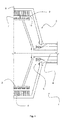
Fig. 1 shows a cross section of a schematic embodiment of anelectrical machine 1 in which aPM generator 2 may be located. Thegenerator 2 may comprise arotor 3 connected to ashaft 4 supported in ashaft support 5 arrangement. Theelectrical machine 1 may further support astator 6. - The
rotor 3 may have one ormore poles 7 and thestator 6 may have one ormore teeth 8 that are separated by agap 9 spaced by a gap distance 10 (in a lateral direction). -
Fig. 2 shows a cross section of a schematic embodiment of thegenerator 2 in which therotor 3 with thepoles 7 may be rotatably arranged inside the electrical machine (not shown). Therotor 3 may be arranged inside thestator 6 with theteeth 8 so that thepoles 7 and theteeth 8 form an electromagnetic coupling extending over thegap 9. - The figure further shows a FEM-simulation of an enlarged area where the
poles 7 and teeth 8 (and the supporting structures) interact magnetically. - Between the
teeth 8 and thepoles 7 there are amagnetic flux intensifier 11 or a configuration intensifying, focusing or collectingmagnetic flux 12 represented by the density of flux lines may be arranged relative to theteeth 8 and thepoles 7. Themagnetic flux intensifier 11 may be arranged between theteeth 8 and thepoles 7. - The
magnetic flux intensifier 11 will allow alarger gap distance 10 for the same magnetic interaction and hence performance of thegenerator 2 thereby allowing for a greater slack. - All things equal and maintaining the
same gap distance 10 will allow for a greater efficiency or a morecompact generator 2. - Equally advantageous precious magnetic materials can be saved by using a
magnetic flux intensifier 11, whilst maintaining thesame gap distance 10 and the same generator power or efficiency. - It is understood that "the same" or "all things equal" means a comparison between a rotor 3' without a
magnetic flux intensifier 11 and arotor 3 with amagnetic flux intensifier 11. -
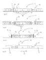
Fig. 3 shows different embodiments (A, B, C, D) of themagnetic flux intensifier 11.Fig. 3A shows an embodiment where thepole 7 may be made of a permanentmagnetic material 13 andmagnetic material 14, i.e. magnetic guiding material in asandwich 15 construction. Thesandwich construction 15 may comprise three layers 16 (I0, II1) of high energy magnetic material 17' placed in a central layer I0 and a layer II1 of low energy magnetic materials 18' placed on both sides of the centre layer I0. A gap III may be finally be located at both sides of the outer layers II1 of the low energy magnetic material 18'. - It is understood that low energy
magnetic materials 18 can be replaced by magnetic guidingmaterials 14, but generally bothlow energy 18 andhigh energy 17 magnetic materials are permanentmagnetic materials 13. -
Fig. 3B shows an embodiment of amagnetic flux intensifier 11 having asandwich construction 15 withfurther layers 16 of the same strong 17 andlow energy 18 magnetic materials placed between the central layer I0 and the gap III. A further layer I2 of the high energymagnetic material 17 may be sided next to the layer II1 of low energymagnetic material 18. A further layer II2 of the low energymagnetic material 18 may be sided next to the further layer I2 of high energymagnetic material 17. -
Fig. 3C shows a generic embodiment of amagnetic flux intensifier 11 having asandwich construction 15 with a predetermined number ofsuccessive layers 16 comprising permanentmagnetic materials 13. In each direction from the centre I0, thelayers 16 extend towards the gap III as Ii, IIi for i=1 to N. -
Fig. 3D shows an embodiment where thelayers 16 are asymmetric. In this particular embodiment, the two layers II1 of low energymagnetic material 18 may have different (arc) lengths where the layer II1 according to a preferredrotational direction 19 of therotor 3. The (arc) length of the layer II1 located near the front of themagnetic flux intensifier 11 facing anadjacent pole 7b in therotation direction 19 may have a greater (arc) length that the same layer II1 facing anadjacent pole 7a in the opposite direction, or vice versa. - The thickness or the (arc) length of the
layers 16 are subject to vary according to design parameters and a person skilled in the art will use either simple experimentation or computational modelling to find the right variations of the layers. - A starting point will be that the
layers 16 from the centre I0 towards to the gap III become thinner and thinner. -
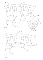
Fig. 4 shows alternative embodiments of themagnetic flux intensifier 11. -
Fig. 4A shows an embodiment, where the pole 7' may be configured with amagnetic flux intensifier 11 having as a trapezoidal cross-sectional shape. The pole 7' may have asandwich construction 15 of at least threelayers 16 where eachlayer 16 may be configured as a circle. -
Fig. 4B shows an embodiment, where thepole 7" may be configured with amagnetic flux intensifier 11 shaped by asingle layer 16 of a high energymagnetic material 17 but with less magnetic material in the outer part of the layer 16' facing theteeth 8 of thestator 6 than in the inner part facing the centre of therotor 3. The layer 16' may form asandwich construction 15 where the outer layers or parts have equivalent magnetic properties compared to the layers of the low energymagnetic material 18. -
Fig. 5 illustrates comparative examples of magnetic interactions for theelectrical machine 1 configured as a wind turbine generator.Fig. 5A shows the generator without amagnetic flux intensifier 11 andfig. 5B shows the generator with amagnetic flux intensifier 11 configuration. - The permanent magnet height is 10 mm and 2269000 mm3 volume per pole or equivalent to 17.0 kg. The gap distance is 6.6 mm.
- A strong magnet material variant of Neodymium is used as the
pole 7 infig. 5A . - A combination of a mixed Ferrite as a low energy
magnetic material 18 and Neodymium as a high energymagnetic material 17 is used infig. 5B . - The effect of using a
magnetic flux intensifier 11 may be scaled to a particular application, such as a generator for a wind turbine. The values based on reliable scaling of dimensions, resources and costs for a 3.6 MW generator are summarised in the following table:Convential Without magnetic flux intensifier according to fig. 5A Invention With magnetic flux intensifier according to fig. 5B Wind Turbine Nominal Power [MW] 5.4 5.4 Rotor diameter [m] 140 140 Rotational speed [rpm] 12.6 12.6 Generator Number of poles 112 112 Outer diameter [m] 7.00 7.00 Active materials [t] 52 41 Estimated costs [kEUR] 516 449 - Thereby the advantages of using a magnetic flux intensifier according to the invention are obvious.
- A person skilled in the art will appreciate, that the
above sandwich construction 15 with a I1, II1, I2, II2-configuration oflayers 16 of high energymagnetic materials 17 and low energymagnetic materials 18 around a central layer I0 of high energymagnetic materials 17 as a starting point. The configuration of thelayers 16 in thesandwich construction 15 may be optimised to a particular application, such as addingmore layers 16 or altering the (arc) lengths of thelayers 16.
| Detailed Description of the | |
| No | Description |
| 1 | |
| 2 | |
| 3 | |
| 4 | |
| 5 | |
| 6 | |
| 7 | |
| 8 | |
| 9 | |
| 10 | |
| 11 | |
| 12 | |
| 13 | |
| 14 | |
| 15 | |
| 16 | Layers, I0, Ii, IIi, III, ... |
| 17 | High energy |
| 18 | Low energy |
| 19 | Rotation direction |
Claims (13)
- An electrical machine (1) comprising:- a rotor (3) configured to rotate in a direction relative to a stator (6), where the rotor comprises one or more poles (7) configured to rotate in an angle relative to a centre of the rotor (3), where the poles (7) are configured to interact with one or more teeth (8) in a stator (6) via an electromagnetic field;- the stator (6) is configured to be fixed in a stationary position in the electrical machine (1), where a gap (9), such as an air gap, is provided between the teeth (8) and the poles (7) in a lateral direction;- at least one magnetic flux intensifier (11) is arranged relative to at least one of the poles (7) and at least one of the teeth (8), where the magnetic flux intensifier (11) is configured to concentrate the magnetic field lines between that pole (7) and that tooth (8) during rotation of the rotor (3)
characterised in that- the magnetic flux intensifier (11) comprises a first type layer (I0) of a high energy magnetic material (17) with magnetic field lines oriented essentially laterally, and at least a second type layer (II1) of a second magnetic material (14, 18) having a magnetic strength that is lower than that of the high energy magnetic material (17), and- where the first type layer (I0) is sided between two second type layers (II1). - An electrical machine (1) according to claim 1, wherein the magnetic flux intensifier (11) is configured as a pole (7) in which the layers (I0, II1,) over an arc length form a sandwich (15) of layers (16) where at least a third type layer (III) forms a gap, e.g. an air gap, between the second type layer (II1) and one of the poles (7) placed adjacent to the magnetic flux intensifier (11).
- An electrical machine (1) according to claim 1 or 2, wherein the magnetic flux intensifier (11) further comprises:- at least another first type layer (I2) which is sided between the second type layers (II1) and the third type layers (III) and comprises a high energy magnetic material (17) with magnetic field lines oriented essentially laterally.
- An electrical machine (1) according to claim 3, wherein the magnetic flux intensifier (11) further comprises:- at least another second type layer (II2) which is sided between the another first type layer (I2) and the third type layer (III) and comprises a second magnetic material (14, 18) having magnetic properties that differs from the properties of the first magnetic material (17).
- An electrical machine (1) according to claim 1 or 2, wherein the magnetic flux intensifier (11)- around a central layer defined by the first type layer (I0) comprises a predetermined number (i=1, 2, ...., N) of successive layers (Ii, IIi), where a first successive type layer (Ii) of a high energy magnetic material (17) is sided by- a second successive type layer (Iii) of a second magnetic material (14, 18) having magnetic properties that differs from the properties of the first magnetic material (17),- and where the successive layers (Ii, IIi) are finished by the third type layer (III).
- An electrical machine (1) according to claim 5, wherein each successive layer type (Ii, IIi) has an arch length that decreases from the central layer (I0) towards the third type layer (III).
- An electrical machine (1) according to claim 5 or 6, wherein the magnetic strength of at least the high energy magnetic material (17) used in each successive layer (Ii) decreases from the central layer (I0) towards the third type layer (III).
- An electrical machine (1) according to any one of claims 5 to 7, wherein at least one of the successive layers (Ii, IIii) located at one side of the central layer (I0) has an arc length that differs from the arc length of the same successive layer (Ii, IIii) located at the opposite side of the central layer (I0).
- An electrical machine according to claim 1 or 2, wherein the magnetic flux intensifier (11) has a trapezoidal shape, wherein the at least three layers (16) are configured as circles.
- An electrical machine (1) according to any one of claim 1 to claim 9, wherein the magnetic material (17) for the first type layer (I) is chosen from a group of magnetic materials having a magnetic remanence Br above 0.5 T or above 1 T or comprises at least neodymium.
- An electrical machine (1) according to any one of claim 1 to claim 10, wherein the magnetic material (18) for the second type layer (II) is chosen from a group of magnetic materials having a magnetic remanence Br below 0.5 T or below 1 Tor is made of iron or a ferrite alloy.
- An electrical machine (1) according to any one of claims 1 to 11, wherein the electrical machine (1) is a generator for generating power or a motor for driving a drivable unit.
- Method of making a pole (7) with a magnetic flux intensifier (11) according to any of claim 1 to claim 12, the method comprising the steps of:- making a plane sandwich of successive first type layers (I) and second type layers (II)- bending the plane sandwich around a centre point of the central first type layer (16') in a curvature as defined by the curvature of a rotor (3) core and the stator (6).
Applications Claiming Priority (1)
| Application Number | Priority Date | Filing Date | Title |
|---|---|---|---|
| DKPA201270486 | 2012-08-17 |
Publications (2)
| Publication Number | Publication Date |
|---|---|
| EP2698905A2 true EP2698905A2 (en) | 2014-02-19 |
| EP2698905A3 EP2698905A3 (en) | 2016-07-27 |
Family
ID=48748078
Family Applications (1)
| Application Number | Title | Priority Date | Filing Date |
|---|---|---|---|
| EP13180741.4A Withdrawn EP2698905A3 (en) | 2012-08-17 | 2013-08-16 | Electrical machine with magnetic flux intensifier |
Country Status (4)
| Country | Link |
|---|---|
| US (1) | US9608483B2 (en) |
| EP (1) | EP2698905A3 (en) |
| CN (1) | CN103595150B (en) |
| CA (1) | CA2822158A1 (en) |
Families Citing this family (2)
| Publication number | Priority date | Publication date | Assignee | Title |
|---|---|---|---|---|
| FR3034917B1 (en) * | 2015-04-07 | 2018-11-09 | Valeo Equipements Electriques Moteur | STARTER STATOR FOR MOTOR VEHICLE WITH OPTIMIZED REMANENCE RANGE |
| CN113508512A (en) * | 2019-03-11 | 2021-10-15 | 西门子歌美飒可再生能源公司 | Permanent magnet assembly comprising three magnet arrangements with different magnetic domain alignment patterns |
Family Cites Families (15)
| Publication number | Priority date | Publication date | Assignee | Title |
|---|---|---|---|---|
| JP3282427B2 (en) | 1994-04-13 | 2002-05-13 | トヨタ自動車株式会社 | Permanent magnet motor |
| SE511896C2 (en) | 1996-12-04 | 1999-12-13 | Vilmos Toeroek | Electric rotary motor with pronounced poles |
| ES2518928T3 (en) | 2002-03-20 | 2014-11-05 | Daikin Industries, Ltd. | Permanent magnet type motor and compressor comprising the same |
| US6879075B2 (en) * | 2003-01-31 | 2005-04-12 | Curtiss-Wright Electro-Mechanical Corporation | Trapezoidal shaped magnet flux intensifier motor pole arrangement for improved motor torque density |
| KR100680201B1 (en) * | 2004-09-17 | 2007-02-08 | 엘지전자 주식회사 | Permanent magnet type motor |
| EP1748533B1 (en) | 2005-07-29 | 2010-09-01 | Siemens Aktiengesellschaft | Rotor with permanent magnets for a brushless electric machine |
| FR2924280B1 (en) | 2007-11-26 | 2015-04-24 | Valeo Equip Electr Moteur | STATOR FOR ROTATING ELECTRICAL MACHINE, IN PARTICULAR A STARTER |
| JP4477072B2 (en) * | 2008-02-13 | 2010-06-09 | 三菱電機株式会社 | Rotating electric machine |
| JP5361261B2 (en) * | 2008-06-20 | 2013-12-04 | 株式会社東芝 | Permanent magnet rotating electric machine |
| CN102204070B (en) * | 2008-07-22 | 2013-09-18 | 阿利发风有限公司 | Permanently excited synchronous machine |
| US8860272B2 (en) | 2010-04-30 | 2014-10-14 | Alstom Hydro France | Synchronous generator, especially for wind turbines |
| US8508092B2 (en) | 2010-11-19 | 2013-08-13 | Toyota Motor Engineering & Manufacturing North America, Inc. | Permanent magnet rotors and methods of manufacturing the same |
| WO2012084031A2 (en) * | 2010-12-22 | 2012-06-28 | Abb Research Ltd | Rotor with incremental poles |
| EP2479872B1 (en) * | 2011-01-25 | 2017-08-30 | Siemens Aktiengesellschaft | Permanently excited synchronous machine with a rotor |
| EP2515417B1 (en) * | 2011-04-18 | 2014-04-02 | Siemens Aktiengesellschaft | A synchronous permanent magnet machine |
-
2013
- 2013-07-29 CA CA2822158A patent/CA2822158A1/en not_active Abandoned
- 2013-07-31 CN CN201310328365.2A patent/CN103595150B/en active Active
- 2013-08-16 EP EP13180741.4A patent/EP2698905A3/en not_active Withdrawn
- 2013-08-16 US US13/968,818 patent/US9608483B2/en not_active Expired - Fee Related
Non-Patent Citations (1)
| Title |
|---|
| None * |
Also Published As
| Publication number | Publication date |
|---|---|
| EP2698905A3 (en) | 2016-07-27 |
| CN103595150B (en) | 2016-09-14 |
| US9608483B2 (en) | 2017-03-28 |
| US20140049131A1 (en) | 2014-02-20 |
| CN103595150A (en) | 2014-02-19 |
| CA2822158A1 (en) | 2014-02-17 |
Similar Documents
| Publication | Publication Date | Title |
|---|---|---|
| US8354767B2 (en) | Permanent magnet rotor with flux concentrating pole pieces | |
| US7960884B2 (en) | Axial gap type rotating machine | |
| US7204012B2 (en) | Method for fabricating a rotor arrangement and a rotor arrangement for an electric machine | |
| US9893571B2 (en) | Permanent magnet type electric rotating machine having main magnets and auxiliary magnets, and manufacturing method thereof | |
| EP1770846B1 (en) | Claw pole rotating electric machine | |
| US7898137B2 (en) | Permanent magnet and permanent magnet rotating machine | |
| US9490685B2 (en) | Axial gap motor using non-rare-earth magnets | |
| EP2800243B1 (en) | Rotor or permanent magnet embedded motor, and compressor, blower, and refrigerating/aitr conditioning device using the rotor | |
| EP2369719B1 (en) | Rotor and permanent magnet rotating machine | |
| US11722027B2 (en) | Rotor for an axial flux motor, a radial flux motor, and a transversal flux motor | |
| CN103973008A (en) | Rotor for permanent magnet type motor, method of manufacturing rotor for permanent magnet type motor, and permanent magnet type motor | |
| CN108462268B (en) | Rotor of rotating electric machine | |
| US20160020656A1 (en) | Electric machine, rotor and associated method | |
| CN102790458A (en) | Permanent magnet auxiliary synchronized reluctance motor rotor and manufacturing method thereof and motor | |
| CN107078617A (en) | Bimorph transducer type circulator | |
| EP2757663A1 (en) | Light weight rotor with Halbach magnetized permanent magnets for large external rotor machines | |
| US9608483B2 (en) | Electrical machine with magnetic flux intensifier | |
| US20150097458A1 (en) | Permanent Magnet Electric Machine | |
| CN106655553B (en) | A kind of composite structure motor | |
| CN105305671A (en) | Cylindrical moving iron-type permanent magnet linear generator | |
| JP2017135857A (en) | Manufacturing method for motor rotor | |
| CN102510143A (en) | Permanent-magnet motor or permanent-magnet generator | |
| JPWO2014046228A1 (en) | Permanent magnet embedded motor |
Legal Events
| Date | Code | Title | Description |
|---|---|---|---|
| AK | Designated contracting states |
Kind code of ref document: A2 Designated state(s): AL AT BE BG CH CY CZ DE DK EE ES FI FR GB GR HR HU IE IS IT LI LT LU LV MC MK MT NL NO PL PT RO RS SE SI SK SM TR |
|
| AX | Request for extension of the european patent |
Extension state: BA ME |
|
| PUAI | Public reference made under article 153(3) epc to a published international application that has entered the european phase |
Free format text: ORIGINAL CODE: 0009012 |
|
| PUAL | Search report despatched |
Free format text: ORIGINAL CODE: 0009013 |
|
| AK | Designated contracting states |
Kind code of ref document: A3 Designated state(s): AL AT BE BG CH CY CZ DE DK EE ES FI FR GB GR HR HU IE IS IT LI LT LU LV MC MK MT NL NO PL PT RO RS SE SI SK SM TR |
|
| AX | Request for extension of the european patent |
Extension state: BA ME |
|
| RIC1 | Information provided on ipc code assigned before grant |
Ipc: H02K 7/18 20060101ALI20160620BHEP Ipc: H02K 1/02 20060101ALI20160620BHEP Ipc: H02K 21/14 20060101AFI20160620BHEP Ipc: H02K 1/27 20060101ALI20160620BHEP |
|
| 17P | Request for examination filed |
Effective date: 20170116 |
|
| RBV | Designated contracting states (corrected) |
Designated state(s): AL AT BE BG CH CY CZ DE DK EE ES FI FR GB GR HR HU IE IS IT LI LT LU LV MC MK MT NL NO PL PT RO RS SE SI SK SM TR |
|
| GRAP | Despatch of communication of intention to grant a patent |
Free format text: ORIGINAL CODE: EPIDOSNIGR1 |
|
| INTG | Intention to grant announced |
Effective date: 20180404 |
|
| RAP1 | Party data changed (applicant data changed or rights of an application transferred) |
Owner name: ENVISION ENERGY (DENMARK) APS |
|
| STAA | Information on the status of an ep patent application or granted ep patent |
Free format text: STATUS: THE APPLICATION IS DEEMED TO BE WITHDRAWN |
|
| 18D | Application deemed to be withdrawn |
Effective date: 20180815 |