EP1895495B1 - Organic electroluminescent display device and driving method for the same - Google Patents
Organic electroluminescent display device and driving method for the same Download PDFInfo
- Publication number
- EP1895495B1 EP1895495B1 EP07104092A EP07104092A EP1895495B1 EP 1895495 B1 EP1895495 B1 EP 1895495B1 EP 07104092 A EP07104092 A EP 07104092A EP 07104092 A EP07104092 A EP 07104092A EP 1895495 B1 EP1895495 B1 EP 1895495B1
- Authority
- EP
- European Patent Office
- Prior art keywords
- voltage
- battery
- data signal
- signal
- pixel
- Prior art date
- Legal status (The legal status is an assumption and is not a legal conclusion. Google has not performed a legal analysis and makes no representation as to the accuracy of the status listed.)
- Active
Links
- 238000000034 method Methods 0.000 title claims description 12
- 238000005401 electroluminescence Methods 0.000 claims description 33
- 238000005070 sampling Methods 0.000 claims description 15
- 239000003990 capacitor Substances 0.000 claims description 5
- 239000003086 colorant Substances 0.000 description 16
- 238000010586 diagram Methods 0.000 description 5
- 239000011159 matrix material Substances 0.000 description 3
- 235000008733 Citrus aurantifolia Nutrition 0.000 description 2
- 235000011941 Tilia x europaea Nutrition 0.000 description 2
- 238000005516 engineering process Methods 0.000 description 2
- 239000004571 lime Substances 0.000 description 2
- 239000004973 liquid crystal related substance Substances 0.000 description 2
- 230000009286 beneficial effect Effects 0.000 description 1
- 230000003247 decreasing effect Effects 0.000 description 1
- 230000005611 electricity Effects 0.000 description 1
- 230000001747 exhibiting effect Effects 0.000 description 1
- 238000012986 modification Methods 0.000 description 1
- 230000004048 modification Effects 0.000 description 1
Images
Classifications
-
- G—PHYSICS
- G09—EDUCATION; CRYPTOGRAPHY; DISPLAY; ADVERTISING; SEALS
- G09G—ARRANGEMENTS OR CIRCUITS FOR CONTROL OF INDICATING DEVICES USING STATIC MEANS TO PRESENT VARIABLE INFORMATION
- G09G3/00—Control arrangements or circuits, of interest only in connection with visual indicators other than cathode-ray tubes
- G09G3/20—Control arrangements or circuits, of interest only in connection with visual indicators other than cathode-ray tubes for presentation of an assembly of a number of characters, e.g. a page, by composing the assembly by combination of individual elements arranged in a matrix no fixed position being assigned to or needed to be assigned to the individual characters or partial characters
- G09G3/22—Control arrangements or circuits, of interest only in connection with visual indicators other than cathode-ray tubes for presentation of an assembly of a number of characters, e.g. a page, by composing the assembly by combination of individual elements arranged in a matrix no fixed position being assigned to or needed to be assigned to the individual characters or partial characters using controlled light sources
- G09G3/30—Control arrangements or circuits, of interest only in connection with visual indicators other than cathode-ray tubes for presentation of an assembly of a number of characters, e.g. a page, by composing the assembly by combination of individual elements arranged in a matrix no fixed position being assigned to or needed to be assigned to the individual characters or partial characters using controlled light sources using electroluminescent panels
- G09G3/32—Control arrangements or circuits, of interest only in connection with visual indicators other than cathode-ray tubes for presentation of an assembly of a number of characters, e.g. a page, by composing the assembly by combination of individual elements arranged in a matrix no fixed position being assigned to or needed to be assigned to the individual characters or partial characters using controlled light sources using electroluminescent panels semiconductive, e.g. using light-emitting diodes [LED]
- G09G3/3208—Control arrangements or circuits, of interest only in connection with visual indicators other than cathode-ray tubes for presentation of an assembly of a number of characters, e.g. a page, by composing the assembly by combination of individual elements arranged in a matrix no fixed position being assigned to or needed to be assigned to the individual characters or partial characters using controlled light sources using electroluminescent panels semiconductive, e.g. using light-emitting diodes [LED] organic, e.g. using organic light-emitting diodes [OLED]
- G09G3/3225—Control arrangements or circuits, of interest only in connection with visual indicators other than cathode-ray tubes for presentation of an assembly of a number of characters, e.g. a page, by composing the assembly by combination of individual elements arranged in a matrix no fixed position being assigned to or needed to be assigned to the individual characters or partial characters using controlled light sources using electroluminescent panels semiconductive, e.g. using light-emitting diodes [LED] organic, e.g. using organic light-emitting diodes [OLED] using an active matrix
- G09G3/3233—Control arrangements or circuits, of interest only in connection with visual indicators other than cathode-ray tubes for presentation of an assembly of a number of characters, e.g. a page, by composing the assembly by combination of individual elements arranged in a matrix no fixed position being assigned to or needed to be assigned to the individual characters or partial characters using controlled light sources using electroluminescent panels semiconductive, e.g. using light-emitting diodes [LED] organic, e.g. using organic light-emitting diodes [OLED] using an active matrix with pixel circuitry controlling the current through the light-emitting element
-
- G—PHYSICS
- G01—MEASURING; TESTING
- G01R—MEASURING ELECTRIC VARIABLES; MEASURING MAGNETIC VARIABLES
- G01R31/00—Arrangements for testing electric properties; Arrangements for locating electric faults; Arrangements for electrical testing characterised by what is being tested not provided for elsewhere
- G01R31/36—Arrangements for testing, measuring or monitoring the electrical condition of accumulators or electric batteries, e.g. capacity or state of charge [SoC]
-
- G—PHYSICS
- G09—EDUCATION; CRYPTOGRAPHY; DISPLAY; ADVERTISING; SEALS
- G09G—ARRANGEMENTS OR CIRCUITS FOR CONTROL OF INDICATING DEVICES USING STATIC MEANS TO PRESENT VARIABLE INFORMATION
- G09G3/00—Control arrangements or circuits, of interest only in connection with visual indicators other than cathode-ray tubes
- G09G3/20—Control arrangements or circuits, of interest only in connection with visual indicators other than cathode-ray tubes for presentation of an assembly of a number of characters, e.g. a page, by composing the assembly by combination of individual elements arranged in a matrix no fixed position being assigned to or needed to be assigned to the individual characters or partial characters
- G09G3/22—Control arrangements or circuits, of interest only in connection with visual indicators other than cathode-ray tubes for presentation of an assembly of a number of characters, e.g. a page, by composing the assembly by combination of individual elements arranged in a matrix no fixed position being assigned to or needed to be assigned to the individual characters or partial characters using controlled light sources
- G09G3/30—Control arrangements or circuits, of interest only in connection with visual indicators other than cathode-ray tubes for presentation of an assembly of a number of characters, e.g. a page, by composing the assembly by combination of individual elements arranged in a matrix no fixed position being assigned to or needed to be assigned to the individual characters or partial characters using controlled light sources using electroluminescent panels
- G09G3/32—Control arrangements or circuits, of interest only in connection with visual indicators other than cathode-ray tubes for presentation of an assembly of a number of characters, e.g. a page, by composing the assembly by combination of individual elements arranged in a matrix no fixed position being assigned to or needed to be assigned to the individual characters or partial characters using controlled light sources using electroluminescent panels semiconductive, e.g. using light-emitting diodes [LED]
- G09G3/3208—Control arrangements or circuits, of interest only in connection with visual indicators other than cathode-ray tubes for presentation of an assembly of a number of characters, e.g. a page, by composing the assembly by combination of individual elements arranged in a matrix no fixed position being assigned to or needed to be assigned to the individual characters or partial characters using controlled light sources using electroluminescent panels semiconductive, e.g. using light-emitting diodes [LED] organic, e.g. using organic light-emitting diodes [OLED]
- G09G3/3275—Details of drivers for data electrodes
- G09G3/3291—Details of drivers for data electrodes in which the data driver supplies a variable data voltage for setting the current through, or the voltage across, the light-emitting elements
-
- G—PHYSICS
- G09—EDUCATION; CRYPTOGRAPHY; DISPLAY; ADVERTISING; SEALS
- G09G—ARRANGEMENTS OR CIRCUITS FOR CONTROL OF INDICATING DEVICES USING STATIC MEANS TO PRESENT VARIABLE INFORMATION
- G09G2300/00—Aspects of the constitution of display devices
- G09G2300/08—Active matrix structure, i.e. with use of active elements, inclusive of non-linear two terminal elements, in the pixels together with light emitting or modulating elements
- G09G2300/0809—Several active elements per pixel in active matrix panels
- G09G2300/0842—Several active elements per pixel in active matrix panels forming a memory circuit, e.g. a dynamic memory with one capacitor
-
- G—PHYSICS
- G09—EDUCATION; CRYPTOGRAPHY; DISPLAY; ADVERTISING; SEALS
- G09G—ARRANGEMENTS OR CIRCUITS FOR CONTROL OF INDICATING DEVICES USING STATIC MEANS TO PRESENT VARIABLE INFORMATION
- G09G2310/00—Command of the display device
- G09G2310/02—Addressing, scanning or driving the display screen or processing steps related thereto
- G09G2310/0264—Details of driving circuits
- G09G2310/027—Details of drivers for data electrodes, the drivers handling digital grey scale data, e.g. use of D/A converters
-
- G—PHYSICS
- G09—EDUCATION; CRYPTOGRAPHY; DISPLAY; ADVERTISING; SEALS
- G09G—ARRANGEMENTS OR CIRCUITS FOR CONTROL OF INDICATING DEVICES USING STATIC MEANS TO PRESENT VARIABLE INFORMATION
- G09G2310/00—Command of the display device
- G09G2310/02—Addressing, scanning or driving the display screen or processing steps related thereto
- G09G2310/0264—Details of driving circuits
- G09G2310/0289—Details of voltage level shifters arranged for use in a driving circuit
-
- G—PHYSICS
- G09—EDUCATION; CRYPTOGRAPHY; DISPLAY; ADVERTISING; SEALS
- G09G—ARRANGEMENTS OR CIRCUITS FOR CONTROL OF INDICATING DEVICES USING STATIC MEANS TO PRESENT VARIABLE INFORMATION
- G09G2330/00—Aspects of power supply; Aspects of display protection and defect management
- G09G2330/02—Details of power systems and of start or stop of display operation
- G09G2330/021—Power management, e.g. power saving
-
- G—PHYSICS
- G09—EDUCATION; CRYPTOGRAPHY; DISPLAY; ADVERTISING; SEALS
- G09G—ARRANGEMENTS OR CIRCUITS FOR CONTROL OF INDICATING DEVICES USING STATIC MEANS TO PRESENT VARIABLE INFORMATION
- G09G2330/00—Aspects of power supply; Aspects of display protection and defect management
- G09G2330/02—Details of power systems and of start or stop of display operation
- G09G2330/028—Generation of voltages supplied to electrode drivers in a matrix display other than LCD
Definitions
- the technological field relates to an organic electroluminescence display device and a driving method for the same, and more particularly to an organic electroluminescence display device capable of reducing power consumption by displaying an image using colors associated with a small power consumption if a residual capacity of a battery is low when the residual capacity of the battery is measured, and driving method for the same.
- a flat panel display is classified into a passive matrix type light emitting display and an active matrix type light emitting display, depending on driving systems of pixels.
- the active matrix type light emitting display which selectively turns on the light in every unit pixel, has been widely used because of beneficial aspects of resolution, contrast, and response time.
- the flat panel display has been used as displays or monitors of information appliances, such as personal computers, mobile phones, PDA, etc.
- a liquid crystal display (LCD) using a liquid crystal panel an organic electroluminescence display device using an organic light emitting diode, and a plasma display panel (PDP) using a plasma panel and the like are widely known technologies for implementing flat panel displays.
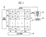
- FIG. 1 is a schematic view showing a conventional organic electroluminescence display device.
- the conventional organic electroluminescence display device includes a pixel unit 10, a data driver 20, a scan driver 30, a power supply unit 40 and a battery 50.
- the pixel unit 10 has a plurality of pixels 11 arranged therein, and luminous elements (not shown) are connected to each of the pixels 11.
- the luminous elements are formed in a horizontal direction and formed in a vertical direction with n number of scan lines (S1,S2,...Sn-1,Sn) for transmitting a scan signal, and they have m number of data lines (D1, D2,....Dm-1, Dm) for transmitting a data signal; the m number of first power supply lines (not shown) transmitting a first power source; the m number of second power supply lines (not shown) transmitting a second power source (ELVss) having a lower electric potential than a first power source (ELVdd).
- the pixel unit 10 displays an image by allowing the luminous elements to emit the light by means of the scan signal, the data signal, the first power source (ELVdd) and the second power source (ELVss).
- the data driver 20 is a unit for applying a data signal to the pixel unit 10, and connected to the data lines (D1, D2,....Dm-1, Dm) of the pixel unit 10 to apply the data signal to the pixel unit 10.
- the scan driver 30 is a unit for sequentially outputting a scan signal and is connected to the scan lines (S1,S2,...Sn-1,Sn) to supply the scan signal to specific rows of the pixel unit 10.
- the data signal input in the data driver 20 is applied to each specific row of the pixel unit 10 to which the scan signal are supplied to display an image, and one frame is completed when all rows are sequentially selected.
- the power supply unit 40 transmits a first power source (ELVdd) and a second power source (ELVss) to the pixel unit 10, the second power source (ELVss) having a lower electric potential than the first power source (ELVdd), and therefore an electric current corresponding to the data signal is allowed to flow in each of the pixels 11 because of a voltage difference of the first power source (ELVdd) and the second power source (ELVss).
- the battery 50 is charged with a predetermined voltage to continuously drive an organic electroluminescence display device without receiving power from an outside power source.
- the voltage charged in the battery 50 is supplied to the power supply unit 40, converted into a voltage required for driving, and output from the power supply unit 40.
- the battery is recharged or not used until it is exchanged if all voltage charged in the battery is discharged.
- the organic electroluminescence display device may not be driven if spare batteries are not present or the used batteries are not recharged.
- US 2004/0201583 and US 2002/0180723 disclose methods for reducing power consumption of an organic electroluminescence display device depending on the residual capacity of the battery.
- aspects of the present invention solve such drawbacks of the prior art, and provides an organic electroluminescence display device capable of extending a functioning period of the battery and, therefore, preventing the display driving from being stopped during its operation because power consumption is reduced by using colors having a low power consumption to display an image.
- a driving method for the same is also disclosed.
- One embodiment is a organic electroluminescence display device including a pixel unit having pixels configured to emit red, green and blue light and to sequentially supply a data signal and a scan signal to each of the pixels to display an image, a data driver configured to supply the data signal to the pixel unit, a scan driver configured to supply the scan signal to the pixel unit, a battery, and a sensor configured to sense a residual charging capacity of the battery, where a voltage of the data signal output from the data driver is controlled by the sensor, depending on the residual charging capacity of the battery.
- the organic electroluminescence display device comprises a means for determining a residual charging capacity of the battery and a means for selecting one voltage of a plurality of bias voltages depending on the residual capacity of the battery and for supplying the selected voltage to the data driver
- Both, the means for determining a residual charging capacity of the battery and the means for selecting the voltage can preferably be integrally formed by a single means.
- the gray levels of the (red, green, blue sub-) pixels are set to 65% - 35% of the maximum gray level to be displayed if the residual charging capacity of the battery is less than 25% of the maximum capacity of the battery and the gray levels of the (red, green, blue sub-) pixels are set to 30% - 20% of the maximum gray level to be displayed if the residual charging capacity of the battery is less than 10% of the maximum capacity of the battery.
- the pixel unit comprises a plurality of pixels, each pixel comprising a red sub-pixel adapted to emit red light, a green sub-pixel adapted green light and a blue sub-pixel adapted to blue light.
- reddish light is also understood as red light
- greenish light is also understood as green light
- bluish light is also understood as blue light
- the data driver comprises: a shift resistor configured to generated a sampling signal; a sampling latch configured to sample a digital data signal based on the sampling signal; a holding latch configured to hold the sampled digital data from the sampling latch and to output the held digital data; a level shifter configured to maintain the held digital data, from the holding latch, to a predetermined voltage, wherein the predetermined voltage is controlled by the signal output by the sensor; and a D/A converter (digital-analog converter) configured to convert the signal from the level shifter to an analog signal.
- the level shifter is directly connected with the sensor.
- the pixel comprises: a first transistor; a second transistor configured to supply the data signal to a gate of the first transistor according to the scan signal; a capacitor configured to store a voltage of the gate in the first transistor for a predetermined period; and an organic light emitting diode configured to receive the driving electric current to emit light.
- the pixel unit is supplied with electric power only by a power supply unit, that is, there is preferably no other power supply for the pixel unit.
- the power supply unit is supplied with electric power only by the battery, that is, there is preferably no other power supply for the power supply unit than the battery.
- the pixel unit, the data driver, the scan driver and the sensor are configured to be driven only by the power which is supplied by the battery without any external power sources.
- Another embodiment is a organic electroluminescence display device including a pixel unit having pixels configured to emit red, green and blue light and to supply a data signal and a scan signal to each of the pixels to display an image, a data driver configured to supply the data signal to the pixel unit, a scan driver configured to supply the scan signal to the pixel unit, a battery, and a sensor configured to sense whether or not the driving power source of the pixel unit is received from the battery, where a voltage of the data signal output from the data driver is controlled by the sensor, depending on whether or not the driving power of the pixel unit is received from the battery.
- the data driver is configured to set the voltage of the data signal to a lower level than a reference value if the power of the pixel unit is received from the battery.
- the red pixels are configured to display one color of maroon and dark red if the voltage of the data signal is set to a lower level than the reference value.
- the blue pixels are configured to display one color of navy blue and dark blue if the voltage of the data signal is set to a lower level than the reference value.
- the sensor is configured to generate a plurality of bias voltages, and one voltage of the plurality of the bias voltages is selected according to whether or not the driving power of the pixel unit is received from the battery.
- a voltage of the data signal supplied to at least one pixel of the red, green and blue pixels is supplied in a low level if the residual capacity of the battery is less than a predetermined value.
- Another embodiment is a method of driving an organic electroluminescence display device which receives power from a battery and uses red, green and blue pixels to display an image.
- the method includes determining a residual capacity of the battery, and controlling a voltage of a data signal if the residual capacity of the battery is less than a predetermined value.
- a voltage of the data signal supplied to at least one pixel of the red, green and blue pixels is supplied in a reduced level if the residual capacity of the battery is less than a predetermined value.
- the red pixels display one color of maroon and dark red colors if the residual capacity of the battery is less than a predetermined value.
- the blue pixels display one color of navy blue and dark blue colors if the residual capacity of the battery is less than a predetermined value.
- Another embodiment is a method of driving an organic electroluminescence display device which receives power from a battery or another power source and uses red, green and blue pixels to display an image.
- the method includes receiving the power from the battery, and adjusting a voltage of a data signal to a lower level if the voltage of the data signal is connected to the other power source.
- the voltage of the data signal supplied to at least one pixel of the red, green and blue pixels is supplied in a reduced level.
- FIG. 1 is a schematic view showing a conventional organic electroluminescence display device.
- FIG. 2 is a schematic view showing an organic electroluminescence display device.
- FIG. 3 is a circuit view showing a configuration of pixels used in the organic electroluminescence display device as shown in FIG. 2 .
- FIG. 4A to FIG. 4C are diagrams showing a difference of power consumption depending on colors.
- FIG. 5 is a schematic view showing a data driver used in the organic electroluminescence display device as shown in FIG. 2 .
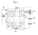
- FIG. 2 is a schematic view showing an organic electroluminescence display device.
- the organic electroluminescence display device includes a pixel unit 100, a data driver 200, a scan driver 300, a power supply unit 400, a battery 500 and a sensor 600.
- the pixel unit 100 includes a plurality of pixels 101 electrically connected to the n number of scan lines (S1,S2,...,Sn) arranged in a horizontal direction, and the m number of data lines (D1,D2,...Dm) arranged in a vertical direction, and each of the pixels 101 receives a first power source (ELVdd) and a second power source (ELVss). Also, a plurality of the pixels 101 include unit pixels for displaying reddish, greenish, or bluish colors, and display a grey level, depending on a voltage of the data signal.
- the data driver 200 is connected to a plurality of the data lines (D1,D2,...Dm), and receives an image signal to generate a data signal and supplies the generated data signal to the pixel unit 100 through the data lines (D1,D2,...Dm).
- the data signal output from the data driver 200 has a value controlled to correspond to a capacity of the battery. If the capacity stored in the battery is large, then the data signal has a high voltage, and if the capacity stored in the battery is small, then the data signal has a low voltage. If the voltage of the data signal is small, then power consumption is lowered due to the low voltage of the data signal. As a result, the period of using electricity charged in the battery may be extended. In some embodiments, lowering a voltage of the data signal is accomplished by using a voltage resulting in 128 grey levels is output, even if a data signal exhibiting 255 grey levels is input, where brightness of the colors is sacrificed.
- the scan driver 300 is connected to the scan lines (S1,S2,...Sn), and supplies a scan signal to the pixel unit 100 through the scan lines.
- the scan signal is sequentially generated, and each row of the pixel unit 100 is sequentially selected by the scan signal, and then the data signal is supplied to the selected rows.
- the power supply unit 400 supplies a first power source (ELVdd) and second power source (ELVss) to the pixel unit 10, the second power source (ELVss) having a lower electric potential than the first power source (ELVdd), thereby to allow an electric current, corresponding to the data signal, to flow in each of the pixels 101 because of a voltage difference between the first power source (ELVdd) and the second power source (ELVss).
- the battery 500 is charged with a predetermined voltage so that the organic electroluminescence display device can be continuously operated without receiving a power source from the outside. And, the voltage charged in the battery 500 is supplied to the power supply unit 400, converted into a voltage required for driving, and output from the power supply unit 400.
- the sensor 600 senses a connection relation to a battery 500, or senses the charged voltage of the battery, and then adjusts a voltage of the data signal output from the data driver 200 to correspond to the charged voltage. If the organic electroluminescence display is driven using the battery 500, then a functional period of the battery is determined according to a charged capacity. Therefore, the battery 500 may not be used for an extended period if it has a high power consumption. If the capacity charged in the battery 500 is small, then the functional period of the battery is particularly short.
- the organic electroluminescence display is driven using the battery 500 (instead of another power source), or if an electric capacity charged in the battery 500 is low, then a voltage of the data signal may be lowered to display an image having a low grey-scale level, and therefore a functional period of the battery 500 may be extended.
- the sensor 600 uses bias voltages, supplied to the data driver 300, to adjust a voltage of the data signal.
- the sensor 600 outputs one voltage of a plurality of the bias voltages if a plurality of the bias voltages are connected to the battery 500 when the sensor 600 senses whether or not a plurality of the bias voltages are connected to the battery 500, or if a residual capacity charged in the battery 500 is low when the sensor 600 senses the charged residual capacity.
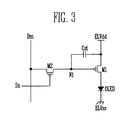
- FIG. 3 is a circuit view showing a configuration for pixels used in the organic electroluminescence display device as shown in FIG. 2 .
- the pixels 101 include a first transistor (M1), a second transistor (M2), a capacitor (Cst) and an organic light emitting diode (OLED).
- M1 first transistor
- M2 second transistor
- Cst capacitor
- OLED organic light emitting diode
- the first transistor (M1) has a source connected to the first power source; a drain connected to the organic light emitting diode (OLED); and a gate connected to a first node (N1), and it controls an electric current that flows in a direction from the source to the drain to correspond to a voltage of the first node (N1).
- the second transistor (M2) has a source connected to the data lines (Dm); a drain connected to the first node (N1); and a gate connected to the scan lines (Sn), and supplies the data signal, supplied through the data lines, to the first node (N1) to correspond to the scan signal supplied through the scan lines (Sn).
- the capacitor (Cst) has a first electrode connected to the first power source (ELVdd); and a second electrode connected to the first node (N1).
- the voltage stored in the capacitor (Cst) is used to maintain a voltage of the data signal supplied to the first node (N1) if the second transistor (M2) is in a turned-off state and the data signal is not supplied to the first node (N1).
- the organic light emitting diode has an emission layer between an anode and a cathode.
- the emission layer emits light as an electric current flows through it.
- the organic light emitting diode (OLED) has an anode connected to a drain of the first transistor (M1); and a cathode connected to the second power source (ELVss), and therefore the organic light emitting diode (OLED) emits the light since an electric current flows in a direction from an anode to a cathode if an electric current flows in a direction from the source to the drain of the first transistor (M1).
- the pixels of the organic electroluminescence display device as configured above, power consumption is increased if a large electric current flows to emission elements, and power consumption is decreased if the electric current is small. That is to say, if a grey-scale level voltage is high, then the electric current flowing to the organic light emitting diode is high and the power consumption is high. Conversely, the power consumption is lower if the grey-scale level voltage is lower.
- Another embodiment is a high grey-scale level of voltage can be input when the organic light emitting diode (OLED) emits red, green and blue light, and particularly the highest grey-scale level voltage can be input when the organic light emitting diode (OLED) emits the red and blue light.
- a grey-scale color having a lower level than the red, green and blue colors may be used to display an image.
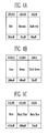
- FIGs. 4A to FIG. 4C are diagrams showing a difference of power consumption depending on colors.
- FIG. 4A is a diagram showing a difference of power consumption of reddish colors
- FIG. 4B is a diagram showing a difference of power consumption of greenish colors
- FIG. 4C is a diagram showing a difference of power consumption of bluish colors.
- the red pixel displays a red color if the maximum 255 grey level voltage is input, and a power consumption is 210 mw if the red pixel displays a red color.
- the red pixel displays a maroon color if a 128 grey level voltage is input, and a power consumption is 85 mw if the red pixel displays a maroon color.
- the red pixel displays a dark red color if a 64 grey level voltage is input, and a power consumption is 40 mw if the red pixel displays a dark red color.
- the green pixel displays a lime color if the maximum 255 grey level voltage is input, a power consumption is 200 mw if the green pixel displays a lime color.
- the green pixel displays a green color if a 128 grey level voltage is input, and a power consumption is 100 mw if the green pixel displays a green color.
- the green pixel displays a dark green color if a 64 grey level voltage is input, and a power consumption is 55 mw if the green pixel displays a dark green color.
- the blue pixel displays a blue color if the maximum 255 grey level voltage is input, a power consumption is 470 mw if the blue pixel displays a blue color.
- the blue pixel displays a navy blue color if a 128 grey level voltage is input, and a power consumption is 200 mw if the blue pixel displays a navy blue color.
- the blue pixel displays a dark blue color if a 64 grey level voltage is input, and a power consumption is 55 mw if the blue pixel displays a dark blue color.
- the voltage of the data signal may be varied to display an image only with the red and blue pixels since the green pixel has a lower power consumption than those of the red and blue pixels.
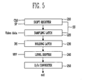
- FIG. 5 is a schematic view showing a data driver used in the organic electroluminescence display device as shown in FIG. 2 .
- the data driver 200 includes a shift resistor 210, a sampling latch 220, a holding latch 230, a level shifter 240 and a D/A converter 250.
- the shift resistor 210 sequentially shifts start pulses (SP) depending on a clock signal (CLK) to generate a sampling signal, to supply the generated sampling signal to the sampling latch 220.
- the sampling latch 220 receives the sampling signal output from the shift resistor 210, and then stores a digital data signal input in series.
- the holding latch 230 receives the digital signal stored in the sampling latch 220, according to a holding signal (DH) supplied from the outside, holds the received digital signal during a first horizontal period, and then outputs the digital signal.
- a holding signal DH
- the level shifter 240 receives a bias voltage from the outside, and then outputs the received bias voltage to a D/A converter 250.
- a voltage of the bias voltage supplied from the outside is received from the sensor 600 as shown in FIG. 2 .
- the sensor 600 selects one voltage of a plurality of the bias voltages and outputs the selected voltage to correspond to the residual capacity of the battery 500. Accordingly, the bias voltages for each color can be adjusted to correspond to the residual capacity of the battery 600.
- the D/A converter 250 is configured to convert the digital signal into an analog signal.
- the bias voltage output from the level shifter 240 is used to convert an output value of the level shifter 240 into an analog signal to supply the converted analog signal to the data lines.
- the organic electroluminescence display device and the driving method for the same may be useful to reduce power consumption by using colors having a lower power consumption than those of red, blue and green colors to display an image having various colors, and particularly to prevent its driving from being stopped during its operation by displaying an image with colors having a low power consumption if a residual capacity of the battery is low.
Applications Claiming Priority (1)
| Application Number | Priority Date | Filing Date | Title |
|---|---|---|---|
| KR1020060083758A KR20080020355A (ko) | 2006-08-31 | 2006-08-31 | 유기전계발광표시장치 및 그의 구동방법 |
Publications (2)
| Publication Number | Publication Date |
|---|---|
| EP1895495A1 EP1895495A1 (en) | 2008-03-05 |
| EP1895495B1 true EP1895495B1 (en) | 2009-02-25 |
Family
ID=38107764
Family Applications (1)
| Application Number | Title | Priority Date | Filing Date |
|---|---|---|---|
| EP07104092A Active EP1895495B1 (en) | 2006-08-31 | 2007-03-14 | Organic electroluminescent display device and driving method for the same |
Country Status (4)
| Country | Link |
|---|---|
| US (1) | US20080055205A1 (ko) |
| EP (1) | EP1895495B1 (ko) |
| KR (1) | KR20080020355A (ko) |
| DE (1) | DE602007000591D1 (ko) |
Families Citing this family (6)
| Publication number | Priority date | Publication date | Assignee | Title |
|---|---|---|---|---|
| KR100894606B1 (ko) | 2007-10-29 | 2009-04-24 | 삼성모바일디스플레이주식회사 | 유기 전계 발광 표시 장치 및 그의 전원 공급 방법 |
| KR100911978B1 (ko) * | 2008-03-10 | 2009-08-13 | 삼성모바일디스플레이주식회사 | 화소 및 이를 이용한 유기전계발광 표시장치 |
| KR101065320B1 (ko) | 2010-02-24 | 2011-09-16 | 삼성모바일디스플레이주식회사 | 유기전계발광표시장치 및 그 구동방법 |
| US9157865B2 (en) * | 2010-05-03 | 2015-10-13 | United Technologies Corporation | Machine tool—based, optical coordinate measuring machine calibration device |
| KR20110138722A (ko) * | 2010-06-21 | 2011-12-28 | 삼성모바일디스플레이주식회사 | 유기발광 표시장치 및 이를 위한 전원 장치 |
| CN102332742A (zh) * | 2011-09-19 | 2012-01-25 | 成都君晟科技有限公司 | 用于随车视频的电源控制系统 |
Family Cites Families (9)
| Publication number | Priority date | Publication date | Assignee | Title |
|---|---|---|---|---|
| GB9808016D0 (en) | 1998-04-15 | 1998-06-17 | Cambridge Display Tech Ltd | Display control |
| US7102632B2 (en) | 2001-06-05 | 2006-09-05 | Eastman Kodak Company | Method for saving power in an organic electroluminescent display |
| KR100555303B1 (ko) * | 2002-12-11 | 2006-03-03 | 엘지.필립스 엘시디 주식회사 | 감마 전압 생성 장치 및 방법 |
| JP4744075B2 (ja) * | 2003-12-04 | 2011-08-10 | ルネサスエレクトロニクス株式会社 | 表示装置、その駆動回路およびその駆動方法 |
| EP1624438B1 (en) * | 2004-07-29 | 2010-09-22 | Thomson Licensing | Method and apparatus for power level control and/or contrast control of a display device |
| JP4285386B2 (ja) * | 2004-10-04 | 2009-06-24 | セイコーエプソン株式会社 | ソースドライバ、電気光学装置及び電子機器 |
| US7679686B2 (en) * | 2004-12-30 | 2010-03-16 | E. I. Du Pont De Nemours And Company | Electronic device comprising a gamma correction unit, a process for using the electronic device, and a data processing system readable medium |
| KR100696693B1 (ko) * | 2005-04-13 | 2007-03-20 | 삼성에스디아이 주식회사 | 유기 발광 표시 장치 |
| US20070146253A1 (en) * | 2005-12-22 | 2007-06-28 | Au Optronics Corporation | Method and device for brightness stabilization in AMOLED display |
-
2006
- 2006-08-31 KR KR1020060083758A patent/KR20080020355A/ko not_active Application Discontinuation
-
2007
- 2007-03-06 US US11/714,607 patent/US20080055205A1/en not_active Abandoned
- 2007-03-14 DE DE602007000591T patent/DE602007000591D1/de active Active
- 2007-03-14 EP EP07104092A patent/EP1895495B1/en active Active
Also Published As
| Publication number | Publication date |
|---|---|
| KR20080020355A (ko) | 2008-03-05 |
| US20080055205A1 (en) | 2008-03-06 |
| EP1895495A1 (en) | 2008-03-05 |
| DE602007000591D1 (de) | 2009-04-09 |
Similar Documents
| Publication | Publication Date | Title |
|---|---|---|
| US11568787B2 (en) | Emission control apparatuses and methods for a display panel | |
| US9595228B2 (en) | Pixel array and organic light emitting display device including the same | |
| US8525756B2 (en) | Organic light emitting display and driving method thereof to characterize pixel parameter values | |
| US20090184896A1 (en) | Organic light emitting display and method of driving the same | |
| US20080062089A1 (en) | Organic electro luminescence display device and driving method for the same | |
| US7843442B2 (en) | Pixel and organic light emitting display using the pixel | |
| US7907137B2 (en) | Display drive apparatus, display apparatus and drive control method thereof | |
| US7782279B2 (en) | Organic light emitting diode display device and driving method thereof | |
| US8456386B2 (en) | Data driver including shift register unit, sampling latch unit, holding latch unit, and digital-to-analog converter, and organic light emitting display using the same | |
| US20080158218A1 (en) | Organic light emitting display and driving method thereof | |
| US8330684B2 (en) | Organic light emitting display and its driving method | |
| KR101310376B1 (ko) | 유기 발광다이오드 표시장치와 그 구동방법 | |
| US20070120868A1 (en) | Method and apparatus for displaying an image | |
| KR20070092856A (ko) | 평판표시장치 및 데이터신호 형성방법 | |
| WO2002077958A1 (fr) | Circuit servant a alimenter un element d'emission lumineuse a matrice active | |
| EP1895495B1 (en) | Organic electroluminescent display device and driving method for the same | |
| KR20110013687A (ko) | 유기전계발광표시장치 및 그의 구동방법 | |
| CN104867445A (zh) | 有机发光显示装置及其驱动方法 | |
| KR100666643B1 (ko) | 유기전계발광표시장치 및 유기전계발광표시장치의 구동방법 | |
| KR100675645B1 (ko) | 전계발광소자의 구동시스템 및 구동방법 | |
| KR100624134B1 (ko) | 유기전계발광표시장치의 구동방법 | |
| KR100546256B1 (ko) | 일렉트로-루미네센스 표시장치 및 그 구동방법 | |
| KR100499373B1 (ko) | 일렉트로 루미네센스 표시장치 및 방법 | |
| KR20080000106A (ko) | 유기발광다이오드 표시소자 및 그의 구동 방법 | |
| KR20030021849A (ko) | 유기 박막 전자 발광 표시 패널과 이를 이용한 유기 박막전자 발광 표시 장치 |
Legal Events
| Date | Code | Title | Description |
|---|---|---|---|
| PUAI | Public reference made under article 153(3) epc to a published international application that has entered the european phase |
Free format text: ORIGINAL CODE: 0009012 |
|
| 17P | Request for examination filed |
Effective date: 20070314 |
|
| AK | Designated contracting states |
Kind code of ref document: A1 Designated state(s): AT BE BG CH CY CZ DE DK EE ES FI FR GB GR HU IE IS IT LI LT LU LV MC MT NL PL PT RO SE SI SK TR |
|
| AX | Request for extension of the european patent |
Extension state: AL BA HR MK YU |
|
| RTI1 | Title (correction) |
Free format text: ORGANIC ELECTROLUMINESCENT DISPLAY DEVICE AND DRIVING METHOD FOR THE SAME |
|
| GRAP | Despatch of communication of intention to grant a patent |
Free format text: ORIGINAL CODE: EPIDOSNIGR1 |
|
| AKX | Designation fees paid |
Designated state(s): DE FR GB |
|
| GRAS | Grant fee paid |
Free format text: ORIGINAL CODE: EPIDOSNIGR3 |
|
| GRAA | (expected) grant |
Free format text: ORIGINAL CODE: 0009210 |
|
| AK | Designated contracting states |
Kind code of ref document: B1 Designated state(s): DE FR GB |
|
| REG | Reference to a national code |
Ref country code: GB Ref legal event code: FG4D |
|
| REF | Corresponds to: |
Ref document number: 602007000591 Country of ref document: DE Date of ref document: 20090409 Kind code of ref document: P |
|
| PLBE | No opposition filed within time limit |
Free format text: ORIGINAL CODE: 0009261 |
|
| STAA | Information on the status of an ep patent application or granted ep patent |
Free format text: STATUS: NO OPPOSITION FILED WITHIN TIME LIMIT |
|
| 26N | No opposition filed |
Effective date: 20091126 |
|
| REG | Reference to a national code |
Ref country code: GB Ref legal event code: 732E Free format text: REGISTERED BETWEEN 20130103 AND 20130109 |
|
| REG | Reference to a national code |
Ref country code: DE Ref legal event code: R082 Ref document number: 602007000591 Country of ref document: DE Representative=s name: GULDE HENGELHAUPT ZIEBIG & SCHNEIDER, DE |
|
| REG | Reference to a national code |
Ref country code: DE Ref legal event code: R082 Ref document number: 602007000591 Country of ref document: DE Representative=s name: GULDE HENGELHAUPT ZIEBIG & SCHNEIDER, DE Effective date: 20130416 Ref country code: DE Ref legal event code: R081 Ref document number: 602007000591 Country of ref document: DE Owner name: SAMSUNG DISPLAY CO., LTD., KR Free format text: FORMER OWNER: SAMSUNG MOBILE DISPLAY CO. LTD., SUWON, KR Effective date: 20130416 Ref country code: DE Ref legal event code: R082 Ref document number: 602007000591 Country of ref document: DE Representative=s name: GULDE & PARTNER PATENT- UND RECHTSANWALTSKANZL, DE Effective date: 20130416 Ref country code: DE Ref legal event code: R081 Ref document number: 602007000591 Country of ref document: DE Owner name: SAMSUNG DISPLAY CO., LTD., YONGIN-CITY, KR Free format text: FORMER OWNER: SAMSUNG MOBILE DISPLAY CO. LTD., SUWON, GYEONGGI, KR Effective date: 20130416 |
|
| REG | Reference to a national code |
Ref country code: FR Ref legal event code: PLFP Year of fee payment: 10 |
|
| REG | Reference to a national code |
Ref country code: FR Ref legal event code: PLFP Year of fee payment: 11 |
|
| REG | Reference to a national code |
Ref country code: FR Ref legal event code: PLFP Year of fee payment: 12 |
|
| PGFP | Annual fee paid to national office [announced via postgrant information from national office to epo] |
Ref country code: FR Payment date: 20230221 Year of fee payment: 17 |
|
| P01 | Opt-out of the competence of the unified patent court (upc) registered |
Effective date: 20230515 |
|
| PGFP | Annual fee paid to national office [announced via postgrant information from national office to epo] |
Ref country code: DE Payment date: 20240220 Year of fee payment: 18 Ref country code: GB Payment date: 20240220 Year of fee payment: 18 |