EP1895148A1 - Intake device of motorcycle - Google Patents
Intake device of motorcycle Download PDFInfo
- Publication number
- EP1895148A1 EP1895148A1 EP07014696A EP07014696A EP1895148A1 EP 1895148 A1 EP1895148 A1 EP 1895148A1 EP 07014696 A EP07014696 A EP 07014696A EP 07014696 A EP07014696 A EP 07014696A EP 1895148 A1 EP1895148 A1 EP 1895148A1
- Authority
- EP
- European Patent Office
- Prior art keywords
- intake
- air cleaner
- duct
- case
- resonators
- Prior art date
- Legal status (The legal status is an assumption and is not a legal conclusion. Google has not performed a legal analysis and makes no representation as to the accuracy of the status listed.)
- Granted
Links
- 238000011144 upstream manufacturing Methods 0.000 claims description 4
- 230000002238 attenuated effect Effects 0.000 description 15
- 238000010276 construction Methods 0.000 description 11
- 239000000446 fuel Substances 0.000 description 11
- 238000010079 rubber tapping Methods 0.000 description 6
- 238000002347 injection Methods 0.000 description 5
- 239000007924 injection Substances 0.000 description 5
- 239000002828 fuel tank Substances 0.000 description 3
- 230000005540 biological transmission Effects 0.000 description 2
- 230000000694 effects Effects 0.000 description 2
- 238000005192 partition Methods 0.000 description 2
- 230000000149 penetrating effect Effects 0.000 description 2
- 230000002093 peripheral effect Effects 0.000 description 2
- XAGFODPZIPBFFR-UHFFFAOYSA-N aluminium Chemical compound [Al] XAGFODPZIPBFFR-UHFFFAOYSA-N 0.000 description 1
- 230000005484 gravity Effects 0.000 description 1
- 239000000203 mixture Substances 0.000 description 1
- 230000002265 prevention Effects 0.000 description 1
- 238000000638 solvent extraction Methods 0.000 description 1
Images


Classifications
-
- F—MECHANICAL ENGINEERING; LIGHTING; HEATING; WEAPONS; BLASTING
- F02—COMBUSTION ENGINES; HOT-GAS OR COMBUSTION-PRODUCT ENGINE PLANTS
- F02M—SUPPLYING COMBUSTION ENGINES IN GENERAL WITH COMBUSTIBLE MIXTURES OR CONSTITUENTS THEREOF
- F02M35/00—Combustion-air cleaners, air intakes, intake silencers, or induction systems specially adapted for, or arranged on, internal-combustion engines
- F02M35/14—Combined air cleaners and silencers
-
- F—MECHANICAL ENGINEERING; LIGHTING; HEATING; WEAPONS; BLASTING
- F02—COMBUSTION ENGINES; HOT-GAS OR COMBUSTION-PRODUCT ENGINE PLANTS
- F02M—SUPPLYING COMBUSTION ENGINES IN GENERAL WITH COMBUSTIBLE MIXTURES OR CONSTITUENTS THEREOF
- F02M35/00—Combustion-air cleaners, air intakes, intake silencers, or induction systems specially adapted for, or arranged on, internal-combustion engines
- F02M35/10—Air intakes; Induction systems
- F02M35/10242—Devices or means connected to or integrated into air intakes; Air intakes combined with other engine or vehicle parts
- F02M35/10295—Damping means, e.g. tranquillising chamber to dampen air oscillations
-
- F—MECHANICAL ENGINEERING; LIGHTING; HEATING; WEAPONS; BLASTING
- F02—COMBUSTION ENGINES; HOT-GAS OR COMBUSTION-PRODUCT ENGINE PLANTS
- F02M—SUPPLYING COMBUSTION ENGINES IN GENERAL WITH COMBUSTIBLE MIXTURES OR CONSTITUENTS THEREOF
- F02M35/00—Combustion-air cleaners, air intakes, intake silencers, or induction systems specially adapted for, or arranged on, internal-combustion engines
- F02M35/12—Intake silencers ; Sound modulation, transmission or amplification
- F02M35/1255—Intake silencers ; Sound modulation, transmission or amplification using resonance
- F02M35/1266—Intake silencers ; Sound modulation, transmission or amplification using resonance comprising multiple chambers or compartments
-
- F—MECHANICAL ENGINEERING; LIGHTING; HEATING; WEAPONS; BLASTING
- F02—COMBUSTION ENGINES; HOT-GAS OR COMBUSTION-PRODUCT ENGINE PLANTS
- F02M—SUPPLYING COMBUSTION ENGINES IN GENERAL WITH COMBUSTIBLE MIXTURES OR CONSTITUENTS THEREOF
- F02M35/00—Combustion-air cleaners, air intakes, intake silencers, or induction systems specially adapted for, or arranged on, internal-combustion engines
- F02M35/16—Combustion-air cleaners, air intakes, intake silencers, or induction systems specially adapted for, or arranged on, internal-combustion engines characterised by use in vehicles
- F02M35/162—Motorcycles; All-terrain vehicles, e.g. quads, snowmobiles; Small vehicles, e.g. forklifts
Definitions
- the present invention relates to an intake system of a motorcycle in which an air cleaner is connected to an upstream side of intake passages connected to intake ports of respective cylinders of an engine, and resonators are provided on the air cleaner.
- the resonators are located apart from the engine as a main source (sound source) of the intake noise, there is concern that the intake noise cannot be attenuated sufficiently.
- the resonators are provided on both side portions of the air cleaner, capacities of the resonators are limited due to limitations on a width dimension of the air cleaner.
- various parts such as a vehicle body frame are disposed in the periphery of the air cleaner, which is regions other than both side portions, there is a problem that it is difficult to arrange the resonators with sufficient capacities.
- the present invention has been made in consideration for the above-described circumstances. It is an object of the present invention to provide an intake system of a motorcycle, which is capable of efficiently attenuating the intake noise and facilitating the arrangement of the resonators.
- the present invention provides an intake system of a motorcycle, in which system an air cleaner is connected to an upstream side of an intake passage connected to an intake port of a cylinder of an engine, and in which system resonators are provided on the air cleaner.
- the air cleaner in the system includes: an air cleaner case having an expansion chamber to which the intake passage is connected and an element; and an intake duct introducing outside air into the air cleaner case.
- the resonators in the system are individually provided on the expansion chamber and the intake duct. According to this invention, the resonators are individually provided on the expansion chamber and the intake duct.
- intake noise can be attenuated at positions close to the engine as a main source of the intake noise, and in addition, the intake noise in the intake duct as an outlet of the intake noise, can be attenuated. In such a way, the intake noise can be attenuated efficiently.
- the resonators are arranged in a dispersed manner, the resonators can be arranged easily.
- a pair of the intake ducts are provided on left and right sides of the air cleaner case, the intake duct on a first side is made longer than the intake duct on a second side, and the capacity of the resonator provided on the intake duct on the first side is made larger than a capacity of the resonator provided on the intake duct on the second side.
- the intake duct on the first side includes an opening/closing valve opening and closing an opening of the intake duct.
- the air cleaner is disposed adjacent to a lower portion of a main tube extended in a fore and aft direction of a vehicle body
- the resonator provided on the expansion chamber is disposed on a side of the main tube on an upper surface of the air cleaner case
- a pair of the intake ducts are provided on left and right sides of the air cleaner case
- the resonators are individually provided on the pair of intake ducts.
- the air cleaner includes: the air cleaner case having the expansion chamber to which the intake passage is connected, and the element; and the intake duct introducing the outside air into the air cleaner case.
- the resonators are individually provided on the expansion chamber and the intake duct. Accordingly, the intake noise can be attenuated at the positions close to the engine as the main source of the intake system, and in addition, the intake noise in the intake duct as the outlet of the intake noise can be attenuated. In such a way, the intake noise can be attenuated efficiently, and in addition, the resonators can be arranged easily.
- the pair of intake ducts are provided on the left and right sides of the air cleaner case, the intake duct on the first side is made longer than the intake duct on the second side, and the capacity of the resonator provided on the intake duct on the first side is made larger than the capacity of the resonator provided on the intake duct on the second side. Accordingly, the duct area and the duct capacity can be made larger, and in addition, the intake noise in the respective intake ducts can be attenuated appropriately.
- the intake duct on the first side includes the opening/closing valve opening and closing the opening of the intake duct, the opening/closing valve can be arranged easily in the intake duct, so that the duct area can be varied.
- the air cleaner is disposed adjacent to the lower portion of the main tube extended in the fore and aft direction of the vehicle body
- the resonator provided on the expansion chamber is disposed on the side of the main tube on the upper surface of the air cleaner case
- the pair of intake ducts are provided on the left and right sides of the air cleaner case
- the resonators are individually provided on the pair of intake ducts. Accordingly, the resonators can be arranged at the positions where the interference thereof with the main tube is avoided.
- Fig. 1 shows a side view of a motorcycle according to this embodiment.
- This motorcycle 1 includes: a vehicle body frame 2; a left and right pair of front forks 3 and 3 freely steerably supported on a front portion of the vehicle body frame 2; a steering handle 4 attached to a top bridge 3A supporting upper ends of the front forks 3 and 3, a front wheel 5 freely rotatably supported on the front forks 3 and 3; an engine 6 supported on the vehicle body frame 2 on a substantial center of a vehicle body; a radiator 7 disposed in front of the engine 6; a swing arm 8 supported on the vehicle body frame 2 in rear of the engine 6 so as to be freely swingable in the up-and-down direction; a rear wheel 9 freely rotatably supported on rear end portions of the swing arm 8; a rear cushion 10 disposed between a rear portion of the swing arm 8 and the vehicle body frame 2; a fuel tank 11 disposed on an upper portion of the vehicle body frame 2; and a seat 12 disposed in rear of the fuel tank 11.
- a headlight 13 Between the top bridge 3A and a bottom bride 3B, which longitudinally support the front forks 3, there are attached a headlight 13, a front cowling 14, direction indicators 15, and meters 16.
- a front fender 17 covering an upper portion of the front wheel 5 is attached.
- a rear cowling 18 and a rear fender 19 are attached to a rear portion of the vehicle body frame 2, and a taillight 20 and direction indicators 21 are attached to the rear cowling 18.
- Fig. 2 is a view showing the vehicle body frame 2.
- a cast frame made of aluminum metal is applied to the vehicle body frame 2.
- the vehicle body frame 2 includes: a head pipe 30; one main tube 31 of an oblong cross-section extended from the head pipe 30 substantially horizontally toward the rear; a left and right pair of down tubes 32 and 32 of an oblong cross-section extended downward from the head pipe 30; and one pivot frame 33 bent from a rear end of the main tube 31 so as to draw a gentle arc and extended downward of the vehicle body.
- One center frame 34 is composed of the main tube 31 and the pivot frame 33.
- seat rail attachment portions 36A and 36B are formed at a longitudinal interval.
- a cushion support portion 37 supporting an upper portion of the rear cushion 10 (refer to Fig. 1) is formed between the seat rail attachment portions 36A and 36B.
- An upper and lower pair of boss portions 38A and 38B are formed left and right in a substantial intermediate portion and lower portion of the pivot frame 33.
- a left and right pair of pivot brackets 39 and 39 are fastened by bolts so as to sandwich the pivot frame 33 from left and right.
- a pivot hole portion 40 (refer to Fig. 2) penetrating therethrough in a vehicle width direction is formed. Front ends of the swing arm 8 are freely rotatably supported through a pivot bolt 41 inserted to the pivot hole portion 40.
- a left and right pair of step holders 44 and 44 extended toward the rear of the vehicle body are attached.
- steps 45 and 45 for a rider are attached, and to rear end portions thereof, steps 46 and 46 for a passenger are attached.
- engine hangers 47 and 48 are individually provided at a longitudinal interval. A rear portion of the engine 6 is supported through the engine hangers 47 and 48, and a front portion of the engine 6 is supported on the down tubes 32 and 32 through brackets 49. In such a way, the engine 6 is supported in a gap surrounded by the center frame 34 and the down tubes 32 and 32, when viewed from a side.
- the engine 6 includes: a crankcase 50; a cylinder block 51 formed integrally with the crankcase 50 so as to be extended substantially upward from a front portion of the crankcase 50; a cylinder head 52 coupled to an upper portion of the cylinder block 51; and a head cover 53 coupled to an upper portion of the cylinder head 52.
- the engine 6 is an in-line four-cylinder engine in which four cylinders are arranged abreast in the cylinder block 51.
- pistons are housed in the respective cylinders so as to freely reciprocate therein.
- a crankshaft coupled to the pistons through connecting rods, and an output shaft 55 of the engine 6 are axially supported.
- intake valves and exhausts valves are arranged, which open and close intake ports and exhaust ports, respectively, in an interlocking manner with a rotation of the crankshaft.
- Sprockets 56 and 57 are provided on the output shaft 55 and the rear wheel 9, respectively, and a drive chain 58 is wound around the sprockets 56 and 57, whereby a chain transmission mechanism is composed. Power of the engine 6 is transmitted to the rear wheel 9 through the chain transmission mechanism.
- exhaust ports 52A individually communicating with the exhaust ports of the respective cylinders are provided.
- Exhaust pipes 60 are individually connected to the respective exhaust ports 52A.
- the respective exhaust pipes 60 are extended downward of the vehicle body from the respective exhaust ports 52A, are extended out below the crankcase 50 toward the rear of the vehicle body, and are connected to a collecting exhaust pipe 61.
- a rear end of the collecting exhaust pipe 61 is connected to a muffler 65.
- the muffler 65 is composed of a first muffler 65A extended below the engine 6 in a fore and aft direction of the vehicle body so as to be adjacent to the collecting exhaust pipe 61, and of a second muffler 65B passing from the first muffler 65A through a space between the engine 6 and the rear wheel 9 to be disposed on a front right side of the rear wheel 9.
- the second muffler 65B disposed on the right side of the vehicle body can be downsized while ensuring sufficient muffler capacity.
- the muffler 65 being a heavy load is disposed close to a center lower portion of the vehicle body to thereby centralize the mass and to lower the center of gravity.
- intake ports 52B individually communicating with the intake ports of the respective cylinders, are provided.
- a fuel injection device 70 is connected to each of the intake ports 52B.
- An air cleaner 80 is coupled to the rear of the fuel injection device 70.
- the fuel injection device 70 includes: throttle bodies 71 having therein valve bodies opening and closing in response to a throttle operation of the user; and four injectors 72, 72, 72 and 72 arranged in the throttle body 71 toward the respective intake ports 52B.
- the fuel injection device 70 adjusts, by the valve bodies, the amount of air supplied from the air cleaner 80 to each cylinder of the engine 6, injects fuel in the fuel tank 11 from the injectors 72, 72, 72 and 72 by control of a control unit (ECU, not shown), and supplies an air-fuel mixture in which fuel and air are mixed together, to the engine 6.
- ECU control unit
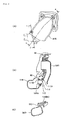
- Fig. 3 is a side view of the air cleaner 80
- Fig. 4 is a perspective view showing an internal structure thereof
- Fig. 5 is a plan view showing the internal structure.
- the air cleaner 80 is disposed adjacent to a lower portion of the main tube 31, and is thereby disposed in a gap between the main tube 31 and the engine 6 as shown in Fig. 1.
- the air cleaner 80 includes: an air cleaner case 83 dividable into a front case 81 and a rear case 82; and a left and right pair of intake ducts 84L and 84R (refer to Fig. 4) introducing the outside air into an internal space (hereinafter, referred to as an expansion chamber RA) of the air cleaner case 83.
- an air cleaner case 83 dividable into a front case 81 and a rear case 82
- a left and right pair of intake ducts 84L and 84R (refer to Fig. 4) introducing the outside air into an internal space (hereinafter, referred to as an expansion chamber RA) of the air cleaner case 83.
- the air cleaner case 83 is formed in a substantially longitudinally oblong box shape extended in the vehicle width direction, in which a longitudinal dimension is longer than a fore and aft depth dimension when viewed from the side. As shown in Fig. 1 and Fig. 3, the air cleaner case 83 is disposed on the vehicle body frame 2 in a posture where a front side thereof is tilting downward. A back surface of the air cleaner case 83, that is, a back surface of the rear case 82 is formed in an inclined surface that is inclined along the main tube 31, whereby the back surface of the air cleaner case 83 can be disposed close to the main tube 31.
- a hose connection port 81A communicating with the inside of the air cleaner case 83 is provided.
- a drain hose is connected to the hose connection port 81A.
- the air funnels 85A, 85B, 85A and 85B include the air funnels 85A with short funnel lengths, and the air funnels 85B with funnel lengths longer than that of the air funnels 85A. These air funnels 85A and 85B of different funnel lengths are alternately arranged. The air funnels 85A and 85B will be expressed below as the air funnels 85, unless it is particularly necessary to distinguish the two.
- Front portions of the air funnels 85 penetrate through the front case 81 and are coupled to the throttle bodies 71.
- Rear portions of the air funnels 85 open in an inside of the upper half portion 82U of the rear case 82. More specifically, the rear portions of the air funnels 85A with short funnel lengths open to the rear case 82 side at positions close to the front case 81, and the rear portions of the air funnels 85B with long funnel lengths are bent in the rear case 82 so as to face obliquely downward toward the rear, and are arranged so that opening portions thereof can be directed to an air cleaner element (hereinafter, referred to as an element) 88 disposed in a lower portion of the rear case 82.
- an air cleaner element hereinafter, referred to as an element
- reference numeral 86 denotes a frame trap provided between the air funnels 85 and the element 88.
- the frame trap 86 composes a prevention wall preventing the element 88 being splashed with the fuel when fuel spitting from the air funnels 85 occurs.
- a cylindrical air filter including an air filter such as filter paper folded at a predetermined length interval is applied to the element 88.
- the element 88 is housed crosswise in a lower half portion 82D of the rear case 82, and both left and right end portions of the element 88, which are outside air inlet ports, communicate with insides of the left and right intake ducts 84L and 84R, respectively, through a through hole portion (not shown) penetrating crosswise through the air cleaner case 83.
- the rear case 82 is formed in a bowl shape so as to form the expansion chamber RA in a space between the front case 81 and itself.
- the element 88 is disposed as described above in the lower portion of the expansion chamber RA.
- the internal space of the element 88 functions as a dark side (outside air chamber) in which the air (outside air) yet to be cleaned is stored.
- the left and right intake ducts 84L and 84R have, when viewed from the side, tube shapes with a substantially oblong cross-section extended substantially horizontally toward the rear from both left and right end portions of the element 88, serving as the base end.
- the intake ducts 84L and 84R capture the outside air from opening portions 84A and 84A open to the rear thereof, introduce the outside air into the element 88 (which is the dark side), and allow the air cleaned by the element 88 to be supplied to the inside of the air cleaner case 83 (clean side).
- the intake ducts 84L and 84R are arranged left and right as described above, whereby a larger duct capacity than in an arrangement of only one intake duct, can be easily ensured.
- the outside air can be efficiently introduced into the element 88 from the left and right sides of the tubular element 88. In such a way, intake resistance can be reduced.
- the intake ducts 84L and 84R are extended substantially horizontally toward the rear, the air warmed by the engine 6 is not taken in, while the relatively low-temperature outside air in a position away from the engine 6 can be introduced to the inside of the air cleaner case 83.
- the left and right intake ducts 84L and 84R have duct shapes different from each other. More specifically, the intake duct 84L on one side (left side of the vehicle body) is formed so that a passage length (so-called duct length) thereof can be longer than a passage length of the intake duct 84R on the other side (right side on the vehicle body), and so that an opening area thereof can be wider.
- Fig. 6(A) is a view of the intake duct 84L viewed from the side
- Fig. 6(B) is a view thereof viewed from above
- Fig. 6(C) shows a b-b cross section of Fig. 6(B).
- an opening/closing valve 89 opening and closing the opening of the duct 84L is disposed.
- a negative pressure of intake passages of the engine 6 is used as a drive source of the valve 89.
- the opening/closing valve 89 has a plate shape, in which a shaft 89A is formed on one end.
- the shaft 89A is freely rotatably supported in the intake duct 84L, whereby the opening/closing valve 89 is supported so as to be freely openable and closable in a direction of arrow R.
- the opening/closing valve 89 is urged to an opening direction by a return spring (not shown), and is constructed so as to close against urging force of the return spring when the negative pressure on the intake side of the engine 6 is applied thereto.
- a partition plate portion 95 partitioning the intake duct 84L into an upper space 84LU and a lower space 84LD is provided in the intake duct 84L.
- An opening of the upper space 84LU partitioned by the partition plate portion 95 is opened and closed by the opening/closing valve 89, whereby the area of the duct is appropriately varied in response to a request from the engine 6.
- the opening/closing valve 89 is disposed in the intake duct 84L with long duct length, and accordingly, the opening/closing valve 89 can be arranged easily.
- the cleaned air introduced from the intake ducts 84L and 84R through the element 88 into the air cleaner case 83 is supplied through the air funnels 85A, 85B, 85A and 85B to the fuel injection device 70, where the cleaned air is mixed with the fuel, and is supplied to the engine 6.
- intake noise is generated, such as valve sounds generated when the intake valves driven in the engine 6 hit the cylinder head 52, and an intake sound generated when the engine 6 aspirates the air.
- the intake noise passes through the intake passages of the engine 6, and in the air cleaner 80, some parts of the intake noise are mutually cancelled to be attenuated, and parts mutually equal in phase, are mutually promoted to be amplified, both of which are emitted from the air cleaner 80 to the outside.
- a case resonator 90 is provided on an upper portion of the air cleaner case 83, and duct resonators 91L and 91R are provided on the left and right intake ducts 84L and 84R, respectively.
- the intake noise is attenuated by these three resonators 90, 91L and 91R.
- Fig. 7 is a view showing the case resonator 90 of the air cleaner case 83 together with the peripheral construction.
- Fig. 8A shows a c-c cross section of Fig. 7, and Fig. 8B shows a d-d cross section of Fig. 7.
- a line L1 indicates a centerline (vehicle fore and aft centerline) in the fore and aft direction of the vehicle body, and a line L2 shows an outline of the center frame 34.
- the case resonator 90 is disposed at a side (right side) position on an upper surface of the air cleaner case 83 (upper surface of the rear case 82) so as to be located on a side (right side) of the main tube 31.
- a through hole 100 is formed at a position close to the respective opening portions of the air funnel 85B and the air funnel 85A, which are located on the right side when viewed from the above.
- a tube 101 is attached, the tube 101 including a sandwiching portion 101A that sandwiches an edge portion of the through hole 100.
- a pipe portion 90A formed integrally with the case resonator 90 is fitted. In such a fitted state, as shown in Fig. 8B, the case resonator 90 is fixed to a boss portion 102 formed on the air cleaner case 83 by a tapping screw 103.
- the case resonator 90 is a resonator generating a resonant wave that is resonant with the intake noise emitted from the engine 6 into the expansion chamber RA of the air cleaner case 83, thereby attenuating the intake noise.
- a capacity of the resonator 90, a length of the pipe portion 90A, an opening area of the pipe portion 90A, and the like are adjusted, whereby, for example, a resonant wave is generated, in which the frequency is substantially the same as the frequency of a standing wave following the intake noise emitted into the expansion chamber RA, and the phase is different from that of the standing wave by 180°, and then the resonant wave and the standing wave are made to interfere with each other, thereby attenuating the standing wave.
- the case resonator 90 is formed in a flat shape going substantially along the upper surface of the air cleaner case 83 (upper surface of the rear case 82), and in addition, is disposed at a more sideward position than the outline L2 of the center frame 34. In such a way, the case resonator 90 avoids interference with the center frame 34 (main tube 31). Moreover, the case resonator 90 suppresses a protrusion amount thereof from the air cleaner 80 while ensuring sufficient capacity, to avoid possible upsizing of the air cleaner 80. Hence, the case resonator 90 can surely avoid interference with various parts arranged in the periphery of the air cleaner 80.
- Fig. 9A is a view of the intake duct 84R viewed from the side together with the duct resonator 91 R
- Fig 9B shows an e-e cross section of Fig. 9A
- Fig. 9C is a view showing an f-f cross-section of Fig. 9A.
- a through hole 110 is formed on an inside wall of the intake duct 84R.
- a tube 111 including a sandwiching portion 111A that sandwiches an edge portion of the through hole 110 is attached.
- an engagement portion 111B is formed, with which a hole portion 91 RA formed in the duct resonator 91R is engaged.
- the duct resonator 91R is fixed to a boss portion 112 formed on the air cleaner case 83, by a tapping screw 113.
- the duct resonator 91R is a resonator generating a resonant wave that is resonant with the intake noise emitted from the engine 6 through the expansion chamber RA of the air cleaner case 83 into the intake duct 84R and with the intake noise generated when the outside air is aspirated into the intake duct 84R, thereby attenuating such intake noise.
- a capacity of the duct resonator 91R, a length of the tube 111, an opening area of the tube 111, and the like are adjusted, whereby, for example, a resonant wave is generated, in which the frequency is substantially the same as the frequency of a standing wave generated in the intake duct 84R, and the phase is different from that of the standing wave by 180°, and then the resonant wave and the standing wave are made to interfere with each other, thereby attenuating the standing wave.
- the duct resonator 91R is disposed on an inner side (vehicle fore and aft centerline L1 side shown in Fig. 7), and is formed in a box shape going substantially along the back surface of the air cleaner case 83. In such a way, the duct resonator 91R can ensure sufficient capacity without projecting from the air cleaner case 83, to avoid possible upsizing of the air cleaner 80.
- the duct resonator 91L on the left side is disposed in a gap formed between the intake duct 84L and the upper half portion 82U of the rear case 82.
- Fig. 10 shows an a-a cross section of Fig. 3. Note that an attachment structure of the duct resonator 91L is substantially the same as the attachment structure of the above-described duct resonator 91R.
- a through hole 120 is formed on an upper wall of the intake duct 84L.
- a tube 121 including a sandwiching portion 121A that sandwiches an edge portion of the through hole 120 is attached to the through hole 120.
- an engagement portion 121B is formed, with which a hole portion 91LA formed in the duct resonator 91L is engaged. Then, in the state where the hole portion 91LA is engaged with the engagement portion 121 B, as shown in Fig. 3, the duct resonator 91L is fixed to the air cleaner case 83 by a tapping screw 123.
- the tapping screw 123 also serves as one of a plurality (three in this construction) of tapping screws 123, 124 and 124 attaching the intake duct 84L to the air cleaner case 83. Hence, the number of tapping screws 123, 124 and 124 to be used is reduced.
- the duct resonator 91L is a resonator generating a resonant wave that is resonant with the intake noise emitted from the engine 6 through the expansion chamber RA of the air cleaner case 83 into the intake duct 84L and with the intake noise generated when the outside air is aspirated into the intake duct 84L, thereby attenuating such intake noise.
- a capacity of the duct resonator 91L, a length of the tube 121, an opening area of the tube 121, and the like are adjusted, whereby, for example, a resonant wave is generated, in which the frequency is substantially the same as the frequency of a standing wave generated in the intake duct 84L, and the phase is different from that of the standing wave by 180°, and then the resonant wave and the standing wave are made to interfere with each other, thereby attenuating the standing wave.
- the duct resonator 91L is formed so that the capacity thereof can be larger than that of the duct resonator 91R provided on the intake duct 84R that is shorter than the intake duct 84L, on which the resonator 91L is provided.
- the duct resonator 91L goes along a gap formed between the intake duct 84L and the upper half portion 82U of the rear case 82, and is formed in a box shape that does not project from the air cleaner case 83 to the outside. In such a way, the duct resonator 91L can ensure sufficient capacity without projecting from the air cleaner case 83 to the side of the vehicle body, and can avoid possible upsizing of the air cleaner 80.
- the case resonator 90 attenuates the intake noise that has just been generated on the engine 6 side and has passed through the air funnel 85. Accordingly, the intake noise can be attenuated at positions close to the engine 6 being a main source (sound source) of the intake noise.
- the duct resonators 91L and 91R attenuate the intake noise in the intake ducts 84L and 84R as outlets of the intake noise. As a result, the intake noise can be efficiently attenuated.
- the plurality of resonators 90, 91R and 91L are arranged on the air cleaner 80 in a dispersed manner. Consequently, the respective resonators 90, 91R and 91L can be downsized while ensuring sufficient capacity as a whole of the resonators, and the resonators can be arranged easily at positions avoiding interference with other parts such as the vehicle body frame 2.
- the present invention may be applied to an air cleaner for a scooter-type motorcycle.
- the number of resonators 90, 91R and 91L is not limited to three. In effect, the resonators just need to be individually provided on the expansion chamber and the intake ducts. For example, a plurality of resonators may be provided on the expansion chamber RA. Furthermore, the shapes of the resonators 90, 91R and 91L are not limited to the shapes described above, and may be changed arbitrarily in dependence with the spaces where these resonators are arranged.
- the invention is directed to an air cleaner including: an air cleaner case having an element and an expansion chamber with an intake passage connected thereto; and intake ducts and introducing outside air into the air cleaner case. Moreover, resonators are provided on the expansion chamber, intake ducts, respectively.
Abstract
Solving Means Provided is an air cleaner (80) including: an air cleaner case (83) having an element and an expansion chamber with an intake passage connected thereto; and intake ducts and introducing outside air into the air cleaner case (83). Moreover, resonators are provided on the expansion chamber, intake ducts, respectively.
Description
- The present invention relates to an intake system of a motorcycle in which an air cleaner is connected to an upstream side of intake passages connected to intake ports of respective cylinders of an engine, and resonators are provided on the air cleaner.
- There is a motorcycle in which an air cleaner is connected to an upstream side of intake passages connected to intake ports of respective cylinders of an engine, and resonators are provided on the air cleaner. In this type of motorcycle, proposed is one in which the resonators are provided on both side portions of an air cleaner case, whereby intake noise of the engine, which is emitted from the air cleaner to the outside, is attenuated by the resonators (for example, refer to
Japanese Patent Application Publication No. JP-A-59-005868 - However, in the conventional construction, since the resonators are located apart from the engine as a main source (sound source) of the intake noise, there is concern that the intake noise cannot be attenuated sufficiently. Moreover, since the resonators are provided on both side portions of the air cleaner, capacities of the resonators are limited due to limitations on a width dimension of the air cleaner. Meanwhile, since various parts such as a vehicle body frame are disposed in the periphery of the air cleaner, which is regions other than both side portions, there is a problem that it is difficult to arrange the resonators with sufficient capacities.
- The present invention has been made in consideration for the above-described circumstances. It is an object of the present invention to provide an intake system of a motorcycle, which is capable of efficiently attenuating the intake noise and facilitating the arrangement of the resonators.
- In order to achieve the above-described object, the present invention provides an intake system of a motorcycle, in which system an air cleaner is connected to an upstream side of an intake passage connected to an intake port of a cylinder of an engine, and in which system resonators are provided on the air cleaner. The air cleaner in the system includes: an air cleaner case having an expansion chamber to which the intake passage is connected and an element; and an intake duct introducing outside air into the air cleaner case. The resonators in the system are individually provided on the expansion chamber and the intake duct. According to this invention, the resonators are individually provided on the expansion chamber and the intake duct. As a result, intake noise can be attenuated at positions close to the engine as a main source of the intake noise, and in addition, the intake noise in the intake duct as an outlet of the intake noise, can be attenuated. In such a way, the intake noise can be attenuated efficiently. Moreover, since the resonators are arranged in a dispersed manner, the resonators can be arranged easily.
- In this case, preferably, a pair of the intake ducts are provided on left and right sides of the air cleaner case, the intake duct on a first side is made longer than the intake duct on a second side, and the capacity of the resonator provided on the intake duct on the first side is made larger than a capacity of the resonator provided on the intake duct on the second side. With this construction, a larger duct area and a larger duct capacity can be obtained, and in addition, the intake noise in the respective intake ducts can be attenuated appropriately. In this case, preferably, the intake duct on the first side includes an opening/closing valve opening and closing an opening of the intake duct. With this construction, the opening/closing valve can be arranged easily in the intake duct, so that the duct area can be varied.
- Moreover, preferably, the air cleaner is disposed adjacent to a lower portion of a main tube extended in a fore and aft direction of a vehicle body, the resonator provided on the expansion chamber is disposed on a side of the main tube on an upper surface of the air cleaner case, a pair of the intake ducts are provided on left and right sides of the air cleaner case, and the resonators are individually provided on the pair of intake ducts. With this construction, the resonators can be arranged at positions where interference thereof with the main tube is avoided.
- In the present invention, the air cleaner includes: the air cleaner case having the expansion chamber to which the intake passage is connected, and the element; and the intake duct introducing the outside air into the air cleaner case. The resonators are individually provided on the expansion chamber and the intake duct. Accordingly, the intake noise can be attenuated at the positions close to the engine as the main source of the intake system, and in addition, the intake noise in the intake duct as the outlet of the intake noise can be attenuated. In such a way, the intake noise can be attenuated efficiently, and in addition, the resonators can be arranged easily.
- Moreover, the pair of intake ducts are provided on the left and right sides of the air cleaner case, the intake duct on the first side is made longer than the intake duct on the second side, and the capacity of the resonator provided on the intake duct on the first side is made larger than the capacity of the resonator provided on the intake duct on the second side. Accordingly, the duct area and the duct capacity can be made larger, and in addition, the intake noise in the respective intake ducts can be attenuated appropriately.
- Furthermore, since the intake duct on the first side includes the opening/closing valve opening and closing the opening of the intake duct, the opening/closing valve can be arranged easily in the intake duct, so that the duct area can be varied.
- Moreover, the air cleaner is disposed adjacent to the lower portion of the main tube extended in the fore and aft direction of the vehicle body, the resonator provided on the expansion chamber is disposed on the side of the main tube on the upper surface of the air cleaner case, the pair of intake ducts are provided on the left and right sides of the air cleaner case, and the resonators are individually provided on the pair of intake ducts. Accordingly, the resonators can be arranged at the positions where the interference thereof with the main tube is avoided.
-
- Fig. 1 is a side view of a motorcycle according to this embodiment.
- Fig. 2 is a perspective view showing a vehicle body frame.
- Fig. 3 is a side view of an air cleaner.
- Fig. 4 is a perspective view showing an internal structure of the air cleaner.
- Fig. 5 is a plan view showing the internal structure of the air cleaner.
- Fig. 6A is a view of a left-side intake duct viewed from a side, Fig. 6B is a view thereof viewed from above, and Fig. 6C is a view showing a b-b cross section of Fig. 6B.
- Fig. 7 is a view showing a case resonator for an air cleaner case together with a peripheral construction.
- Fig. 8A shows a c-c cross section of Fig. 7, and Fig. 8B is a view showing a d-d cross section of Fig. 7.
- Fig. 9A is a view of a right-side intake duct viewed from a side together with a duct resonator, Fig. 9B is a view showing an e-e cross section of Fig. 9A, and Fig. 9C is a view showing an f-f cross section of Fig. 9A.
- Fig. 10 is a view showing an a-a cross section of Fig. 3.
- An explanation will be made below on an embodiment of the present invention with reference to the accompanying drawings. Note that, in the explanation, descriptions of directions such as front and rear, left and right, and upper and lower are defined with respect to a vehicle body.
- Fig. 1 shows a side view of a motorcycle according to this embodiment. This
motorcycle 1 includes: avehicle body frame 2; a left and right pair offront forks vehicle body frame 2; asteering handle 4 attached to atop bridge 3A supporting upper ends of thefront forks front wheel 5 freely rotatably supported on thefront forks vehicle body frame 2 on a substantial center of a vehicle body; a radiator 7 disposed in front of the engine 6; aswing arm 8 supported on thevehicle body frame 2 in rear of the engine 6 so as to be freely swingable in the up-and-down direction; arear wheel 9 freely rotatably supported on rear end portions of theswing arm 8; arear cushion 10 disposed between a rear portion of theswing arm 8 and thevehicle body frame 2; afuel tank 11 disposed on an upper portion of thevehicle body frame 2; and aseat 12 disposed in rear of thefuel tank 11. - Between the
top bridge 3A and abottom bride 3B, which longitudinally support thefront forks 3, there are attached aheadlight 13, a front cowling 14,direction indicators 15, andmeters 16. To thefront forks front fender 17 covering an upper portion of thefront wheel 5 is attached. Moreover, arear cowling 18 and arear fender 19 are attached to a rear portion of thevehicle body frame 2, and ataillight 20 anddirection indicators 21 are attached to therear cowling 18. - Fig. 2 is a view showing the
vehicle body frame 2. A cast frame made of aluminum metal is applied to thevehicle body frame 2. Thevehicle body frame 2 includes: ahead pipe 30; onemain tube 31 of an oblong cross-section extended from thehead pipe 30 substantially horizontally toward the rear; a left and right pair ofdown tubes head pipe 30; and onepivot frame 33 bent from a rear end of themain tube 31 so as to draw a gentle arc and extended downward of the vehicle body. Onecenter frame 34 is composed of themain tube 31 and thepivot frame 33. - On an upper portion of the
pivot frame 33, seatrail attachment portions rail attachment portions cushion support portion 37 supporting an upper portion of the rear cushion 10 (refer to Fig. 1) is formed between the seatrail attachment portions - An upper and lower pair of
boss portions pivot frame 33. As shown in Fig. 1, to theboss portions pivot brackets pivot frame 33 from left and right. In thepivot frame 33 and the left and right pair ofpivot brackets swing arm 8 are freely rotatably supported through apivot bolt 41 inserted to thepivot hole portion 40. - To the
pivot brackets 39, a left and right pair ofstep holders right step holders - Moreover, as shown in Fig. 1 and Fig. 2, to the
pivot frame 33,engine hangers engine hangers down tubes brackets 49. In such a way, the engine 6 is supported in a gap surrounded by thecenter frame 34 and thedown tubes - As shown in Fig. 1, the engine 6 includes: a crankcase 50; a cylinder block 51 formed integrally with the crankcase 50 so as to be extended substantially upward from a front portion of the crankcase 50; a
cylinder head 52 coupled to an upper portion of the cylinder block 51; and ahead cover 53 coupled to an upper portion of thecylinder head 52. The engine 6 is an in-line four-cylinder engine in which four cylinders are arranged abreast in the cylinder block 51. - In the cylinder block 51, pistons are housed in the respective cylinders so as to freely reciprocate therein. In the crankcase 50, a crankshaft coupled to the pistons through connecting rods, and an
output shaft 55 of the engine 6 are axially supported. In thecylinder head 52, intake valves and exhausts valves are arranged, which open and close intake ports and exhaust ports, respectively, in an interlocking manner with a rotation of the crankshaft.Sprockets output shaft 55 and therear wheel 9, respectively, and adrive chain 58 is wound around thesprockets rear wheel 9 through the chain transmission mechanism. - On a front surface of the
cylinder head 52,exhaust ports 52A individually communicating with the exhaust ports of the respective cylinders are provided. Exhaust pipes 60 are individually connected to therespective exhaust ports 52A. The respective exhaust pipes 60 are extended downward of the vehicle body from therespective exhaust ports 52A, are extended out below the crankcase 50 toward the rear of the vehicle body, and are connected to a collectingexhaust pipe 61. A rear end of the collectingexhaust pipe 61 is connected to amuffler 65. In this construction, themuffler 65 is composed of afirst muffler 65A extended below the engine 6 in a fore and aft direction of the vehicle body so as to be adjacent to the collectingexhaust pipe 61, and of asecond muffler 65B passing from thefirst muffler 65A through a space between the engine 6 and therear wheel 9 to be disposed on a front right side of therear wheel 9. With this construction of the muffler, thesecond muffler 65B disposed on the right side of the vehicle body can be downsized while ensuring sufficient muffler capacity. Moreover, themuffler 65 being a heavy load is disposed close to a center lower portion of the vehicle body to thereby centralize the mass and to lower the center of gravity. - On a back surface of the
cylinder head 52,intake ports 52B individually communicating with the intake ports of the respective cylinders, are provided. Afuel injection device 70 is connected to each of theintake ports 52B. Anair cleaner 80 is coupled to the rear of thefuel injection device 70. - The
fuel injection device 70 includes: throttlebodies 71 having therein valve bodies opening and closing in response to a throttle operation of the user; and fourinjectors throttle body 71 toward therespective intake ports 52B. Thefuel injection device 70 adjusts, by the valve bodies, the amount of air supplied from theair cleaner 80 to each cylinder of the engine 6, injects fuel in thefuel tank 11 from theinjectors - Fig. 3 is a side view of the
air cleaner 80, Fig. 4 is a perspective view showing an internal structure thereof, and Fig. 5 is a plan view showing the internal structure. Theair cleaner 80 is disposed adjacent to a lower portion of themain tube 31, and is thereby disposed in a gap between themain tube 31 and the engine 6 as shown in Fig. 1. - As shown in Fig. 3, the
air cleaner 80 includes: an aircleaner case 83 dividable into afront case 81 and arear case 82; and a left and right pair ofintake ducts air cleaner case 83. - The
air cleaner case 83 is formed in a substantially longitudinally oblong box shape extended in the vehicle width direction, in which a longitudinal dimension is longer than a fore and aft depth dimension when viewed from the side. As shown in Fig. 1 and Fig. 3, theair cleaner case 83 is disposed on thevehicle body frame 2 in a posture where a front side thereof is tilting downward. A back surface of theair cleaner case 83, that is, a back surface of therear case 82 is formed in an inclined surface that is inclined along themain tube 31, whereby the back surface of theair cleaner case 83 can be disposed close to themain tube 31. - As shown in Fig. 3 and Fig. 4, in an
upper half portion 81 U of thefront case 81, four air funnels 85A, 85B, 85A and 85B are arranged abreast at an interval, and alower half portion 81 D of thefront case 81 is formed in a shape protruding forward in order to ensure the capacity of the expansion chamber RA of theair cleaner 80. Moreover, on a lower portion of thefront case 81, a hose connection port 81A communicating with the inside of theair cleaner case 83 is provided. A drain hose is connected to the hose connection port 81A. - The air funnels 85A, 85B, 85A and 85B include the air funnels 85A with short funnel lengths, and the air funnels 85B with funnel lengths longer than that of the air funnels 85A. These air funnels 85A and 85B of different funnel lengths are alternately arranged. The air funnels 85A and 85B will be expressed below as the air funnels 85, unless it is particularly necessary to distinguish the two.
- Front portions of the air funnels 85 penetrate through the
front case 81 and are coupled to thethrottle bodies 71. Rear portions of the air funnels 85 open in an inside of theupper half portion 82U of therear case 82. More specifically, the rear portions of the air funnels 85A with short funnel lengths open to therear case 82 side at positions close to thefront case 81, and the rear portions of the air funnels 85B with long funnel lengths are bent in therear case 82 so as to face obliquely downward toward the rear, and are arranged so that opening portions thereof can be directed to an air cleaner element (hereinafter, referred to as an element) 88 disposed in a lower portion of therear case 82. - Note that, in Fig. 5,
reference numeral 86 denotes a frame trap provided between the air funnels 85 and theelement 88. Theframe trap 86 composes a prevention wall preventing theelement 88 being splashed with the fuel when fuel spitting from the air funnels 85 occurs. - To the
element 88, a cylindrical air filter including an air filter such as filter paper folded at a predetermined length interval is applied. As shown in Fig. 4 and Fig. 5, theelement 88 is housed crosswise in alower half portion 82D of therear case 82, and both left and right end portions of theelement 88, which are outside air inlet ports, communicate with insides of the left andright intake ducts air cleaner case 83. - The
rear case 82 is formed in a bowl shape so as to form the expansion chamber RA in a space between thefront case 81 and itself. Theelement 88 is disposed as described above in the lower portion of the expansion chamber RA. A space in the expansion chamber RA, which is around theelement 88, becomes a clean side (clean air chamber) in which the air cleaned by theelement 88 is stored. The internal space of theelement 88 functions as a dark side (outside air chamber) in which the air (outside air) yet to be cleaned is stored. - The left and
right intake ducts element 88, serving as the base end. Theintake ducts portions element 88 to be supplied to the inside of the air cleaner case 83 (clean side). - The
intake ducts element 88 from the left and right sides of thetubular element 88. In such a way, intake resistance can be reduced. Moreover, since theintake ducts air cleaner case 83. - The left and
right intake ducts intake duct 84L on one side (left side of the vehicle body) is formed so that a passage length (so-called duct length) thereof can be longer than a passage length of theintake duct 84R on the other side (right side on the vehicle body), and so that an opening area thereof can be wider. - Fig. 6(A) is a view of the
intake duct 84L viewed from the side, Fig. 6(B) is a view thereof viewed from above, and Fig. 6(C) shows a b-b cross section of Fig. 6(B). In theintake duct 84L on one side (left side of the vehicle body), which has a larger capacity, an opening/closingvalve 89 opening and closing the opening of theduct 84L is disposed. As a drive source of thevalve 89, a negative pressure of intake passages of the engine 6 is used. - More specifically, as shown in Figs. 6B and 6C, the opening/closing
valve 89 has a plate shape, in which ashaft 89A is formed on one end. Theshaft 89A is freely rotatably supported in theintake duct 84L, whereby the opening/closingvalve 89 is supported so as to be freely openable and closable in a direction of arrow R. The opening/closingvalve 89 is urged to an opening direction by a return spring (not shown), and is constructed so as to close against urging force of the return spring when the negative pressure on the intake side of the engine 6 is applied thereto. In this construction, in theintake duct 84L, apartition plate portion 95 partitioning theintake duct 84L into an upper space 84LU and a lower space 84LD is provided. An opening of the upper space 84LU partitioned by thepartition plate portion 95 is opened and closed by the opening/closingvalve 89, whereby the area of the duct is appropriately varied in response to a request from the engine 6. In this case, the opening/closingvalve 89 is disposed in theintake duct 84L with long duct length, and accordingly, the opening/closingvalve 89 can be arranged easily. - In response to the negative pressure on the intake side of the engine 6, the cleaned air introduced from the
intake ducts element 88 into theair cleaner case 83 is supplied through the air funnels 85A, 85B, 85A and 85B to thefuel injection device 70, where the cleaned air is mixed with the fuel, and is supplied to the engine 6. - Incidentally, when the engine 6 is driven, intake noise is generated, such as valve sounds generated when the intake valves driven in the engine 6 hit the
cylinder head 52, and an intake sound generated when the engine 6 aspirates the air. The intake noise passes through the intake passages of the engine 6, and in theair cleaner 80, some parts of the intake noise are mutually cancelled to be attenuated, and parts mutually equal in phase, are mutually promoted to be amplified, both of which are emitted from theair cleaner 80 to the outside. - In the
air cleaner 80 of the present construction, for the purpose of reducing the intake noise emitted to the outside, as shown in Fig. 3 to Fig. 5, acase resonator 90 is provided on an upper portion of theair cleaner case 83, andduct resonators right intake ducts resonators - Next, a description will be made in detail of the
case resonator 90 and theduct resonators case resonator 90 of theair cleaner case 83 together with the peripheral construction. Fig. 8A shows a c-c cross section of Fig. 7, and Fig. 8B shows a d-d cross section of Fig. 7. Note that, in Fig. 7, a line L1 indicates a centerline (vehicle fore and aft centerline) in the fore and aft direction of the vehicle body, and a line L2 shows an outline of thecenter frame 34. - As shown in Fig. 7, the
case resonator 90 is disposed at a side (right side) position on an upper surface of the air cleaner case 83 (upper surface of the rear case 82) so as to be located on a side (right side) of themain tube 31. - More specifically, on the upper surface of the
air cleaner case 83, as shown in Fig. 5, a throughhole 100 is formed at a position close to the respective opening portions of theair funnel 85B and theair funnel 85A, which are located on the right side when viewed from the above. To the throughhole 100, as shown in Fig. 8A, atube 101 is attached, thetube 101 including asandwiching portion 101A that sandwiches an edge portion of the throughhole 100. To thetube 101, apipe portion 90A formed integrally with thecase resonator 90 is fitted. In such a fitted state, as shown in Fig. 8B, thecase resonator 90 is fixed to aboss portion 102 formed on theair cleaner case 83 by a tappingscrew 103. - The
case resonator 90 is a resonator generating a resonant wave that is resonant with the intake noise emitted from the engine 6 into the expansion chamber RA of theair cleaner case 83, thereby attenuating the intake noise. Specifically, a capacity of theresonator 90, a length of thepipe portion 90A, an opening area of thepipe portion 90A, and the like are adjusted, whereby, for example, a resonant wave is generated, in which the frequency is substantially the same as the frequency of a standing wave following the intake noise emitted into the expansion chamber RA, and the phase is different from that of the standing wave by 180°, and then the resonant wave and the standing wave are made to interfere with each other, thereby attenuating the standing wave. - Moreover, as shown in Fig. 7 and Fig. 8A, the
case resonator 90 is formed in a flat shape going substantially along the upper surface of the air cleaner case 83 (upper surface of the rear case 82), and in addition, is disposed at a more sideward position than the outline L2 of thecenter frame 34. In such a way, thecase resonator 90 avoids interference with the center frame 34 (main tube 31). Moreover, thecase resonator 90 suppresses a protrusion amount thereof from theair cleaner 80 while ensuring sufficient capacity, to avoid possible upsizing of theair cleaner 80. Hence, thecase resonator 90 can surely avoid interference with various parts arranged in the periphery of theair cleaner 80. - Moreover, as shown in Fig. 7, the
duct resonator 91 R on the right side is disposed on an inner side (vehicle fore and aft centerline L1 side) in the vicinity of an opening portion of theintake duct 84R. Fig. 9A is a view of theintake duct 84R viewed from the side together with theduct resonator 91 R, Fig 9B shows an e-e cross section of Fig. 9A, and Fig. 9C is a view showing an f-f cross-section of Fig. 9A. - As shown in Fig. 9(B), a through
hole 110 is formed on an inside wall of theintake duct 84R. To the throughhole 110, atube 111 including asandwiching portion 111A that sandwiches an edge portion of the throughhole 110 is attached. - In the
tube 111, on an end portion thereof opposite from the sandwichingportion 111A, anengagement portion 111B is formed, with which a hole portion 91 RA formed in theduct resonator 91R is engaged. In a state where the hole portion 91RA is engaged with theengagement portion 111B, as shown in Fig. 9C, theduct resonator 91R is fixed to aboss portion 112 formed on theair cleaner case 83, by a tappingscrew 113. - The
duct resonator 91R is a resonator generating a resonant wave that is resonant with the intake noise emitted from the engine 6 through the expansion chamber RA of theair cleaner case 83 into theintake duct 84R and with the intake noise generated when the outside air is aspirated into theintake duct 84R, thereby attenuating such intake noise. Specifically, a capacity of theduct resonator 91R, a length of thetube 111, an opening area of thetube 111, and the like are adjusted, whereby, for example, a resonant wave is generated, in which the frequency is substantially the same as the frequency of a standing wave generated in theintake duct 84R, and the phase is different from that of the standing wave by 180°, and then the resonant wave and the standing wave are made to interfere with each other, thereby attenuating the standing wave. - Moreover, the
duct resonator 91R is disposed on an inner side (vehicle fore and aft centerline L1 side shown in Fig. 7), and is formed in a box shape going substantially along the back surface of theair cleaner case 83. In such a way, theduct resonator 91R can ensure sufficient capacity without projecting from theair cleaner case 83, to avoid possible upsizing of theair cleaner 80. - As shown in FIG. 3, the
duct resonator 91L on the left side is disposed in a gap formed between theintake duct 84L and theupper half portion 82U of therear case 82. Fig. 10 shows an a-a cross section of Fig. 3. Note that an attachment structure of theduct resonator 91L is substantially the same as the attachment structure of the above-describedduct resonator 91R. - Describing in detail, as shown in Fig. 10, a through
hole 120 is formed on an upper wall of theintake duct 84L. To the throughhole 120, atube 121 including asandwiching portion 121A that sandwiches an edge portion of the throughhole 120 is attached. In thetube 121, on an end portion thereof opposite from the sandwichingportion 121A, anengagement portion 121B is formed, with which a hole portion 91LA formed in theduct resonator 91L is engaged. Then, in the state where the hole portion 91LA is engaged with theengagement portion 121 B, as shown in Fig. 3, theduct resonator 91L is fixed to theair cleaner case 83 by a tappingscrew 123. - As shown in Fig. 3, the tapping
screw 123 also serves as one of a plurality (three in this construction) of tappingscrews intake duct 84L to theair cleaner case 83. Hence, the number of tappingscrews - The
duct resonator 91L is a resonator generating a resonant wave that is resonant with the intake noise emitted from the engine 6 through the expansion chamber RA of theair cleaner case 83 into theintake duct 84L and with the intake noise generated when the outside air is aspirated into theintake duct 84L, thereby attenuating such intake noise. Specifically, a capacity of theduct resonator 91L, a length of thetube 121, an opening area of thetube 121, and the like are adjusted, whereby, for example, a resonant wave is generated, in which the frequency is substantially the same as the frequency of a standing wave generated in theintake duct 84L, and the phase is different from that of the standing wave by 180°, and then the resonant wave and the standing wave are made to interfere with each other, thereby attenuating the standing wave. In this case, theduct resonator 91L is formed so that the capacity thereof can be larger than that of theduct resonator 91R provided on theintake duct 84R that is shorter than theintake duct 84L, on which theresonator 91L is provided. - Moreover, the
duct resonator 91L goes along a gap formed between theintake duct 84L and theupper half portion 82U of therear case 82, and is formed in a box shape that does not project from theair cleaner case 83 to the outside. In such a way, theduct resonator 91L can ensure sufficient capacity without projecting from theair cleaner case 83 to the side of the vehicle body, and can avoid possible upsizing of theair cleaner 80. - As described above, in this embodiment, provided are the
case resonator 90 attenuating the sound in the expansion chamber RA of theair cleaner 80, and theduct resonators intake ducts resonators air cleaner 80 and the intake noise generated when the outside air is aspirated into theair cleaner 80, can be attenuated. - In this case, the
case resonator 90 attenuates the intake noise that has just been generated on the engine 6 side and has passed through the air funnel 85. Accordingly, the intake noise can be attenuated at positions close to the engine 6 being a main source (sound source) of the intake noise. In addition, theduct resonators intake ducts - In addition, the plurality of
resonators air cleaner 80 in a dispersed manner. Consequently, therespective resonators vehicle body frame 2. - As above, the description has been made of the present invention on the basis of the embodiment; however, it is obvious that the present invention is not limited to this. For example, in the above-described embodiment, the description has been made of the case where the present invention is applied to the
air cleaner 80 for a motorcycle including an in-line four-cylinder engine; however, without being limited to this, the present invention is widely applicable to publicly known air cleaners such as air cleaners for motorcycles including other multi-cylinder engines such as a V-type engine, and a single-cylinder engine. Moreover, the present invention may be applied to an air cleaner for a scooter-type motorcycle. - Furthermore, the number of
resonators resonators - To provide an intake system of a motor cycle, which is capable of attenuating intake noise efficiently, and facilitating arrangement of resonators, the invention is directed to an air cleaner including: an air cleaner case having an element and an expansion chamber with an intake passage connected thereto; and intake ducts and introducing outside air into the air cleaner case. Moreover, resonators are provided on the expansion chamber, intake ducts, respectively.
Claims (4)
- An intake system of a motorcycle (1) in which an air cleaner (80) is connected to an upstream side of an intake passage connected to an intake port of a cylinder of an engine (6), and resonators are provided on this air cleaner (80), wherein
the air cleaner (80) includes: an air cleaner case (83) having an expansion chamber to which the intake passage is connected, and an element (88); and an intake duct (84L, 84R) introducing outside air into the air cleaner case (83), and
the resonators are individually provided on the expansion chamber and the intake duct (84L, 84R). - The intake system of a motorcycle (1) according to claim 1, wherein a pair of the intake ducts (84L, 84R) are provided on left and right sides of the air cleaner case (83), the intake duct (84L, 84R) on a first side is made longer than the intake duct (84L, 84R) on a second side, and a capacity of the resonator provided on the intake duct (84L, 84R) on the first side is made larger than a capacity of the resonator provided on the intake duct (84L, 84R) on the second side.
- The intake system of a motorcycle (1) according to claim 2, wherein the intake duct (84L, 84R) on the first side includes an opening/closing valve opening (89) and closing an opening of the intake duct (84L, 84R).
- The intake system of a motorcycle (1) according to any one of claims 1 to 3, wherein the air cleaner (80) is disposed adjacent to a lower portion of a main tube (101, 111, 121) extended in a fore and aft direction of a vehicle body, the resonator provided on the expansion chamber is disposed on a side of the main tube on an upper surface of the air cleaner case (83), a pair of the intake ducts (84L, 84R) are provided on left and right sides of the air cleaner case (83), and the resonators are individually provided on the pair of intake ducts (84L, 84R).
Applications Claiming Priority (1)
| Application Number | Priority Date | Filing Date | Title |
|---|---|---|---|
| JP2006238577A JP4630854B2 (en) | 2006-09-04 | 2006-09-04 | Intake device for motorcycle |
Publications (2)
| Publication Number | Publication Date |
|---|---|
| EP1895148A1 true EP1895148A1 (en) | 2008-03-05 |
| EP1895148B1 EP1895148B1 (en) | 2012-10-03 |
Family
ID=38474057
Family Applications (1)
| Application Number | Title | Priority Date | Filing Date |
|---|---|---|---|
| EP07014696A Expired - Fee Related EP1895148B1 (en) | 2006-09-04 | 2007-07-26 | Intake device of motorcycle |
Country Status (8)
| Country | Link |
|---|---|
| US (1) | US7614380B2 (en) |
| EP (1) | EP1895148B1 (en) |
| JP (1) | JP4630854B2 (en) |
| CN (1) | CN101139962B (en) |
| AR (1) | AR062293A1 (en) |
| BR (1) | BRPI0703874A (en) |
| CO (1) | CO5950119A1 (en) |
| PE (1) | PE20081040A1 (en) |
Families Citing this family (18)
| Publication number | Priority date | Publication date | Assignee | Title |
|---|---|---|---|---|
| JP5215593B2 (en) * | 2007-05-24 | 2013-06-19 | 富士重工業株式会社 | Air cleaner |
| JP2009047247A (en) * | 2007-08-20 | 2009-03-05 | Yamaha Motor Co Ltd | Air cleaner, case of continuously variable transmission, engine unit, and saddle-riding vehicle |
| JP2009046017A (en) * | 2007-08-20 | 2009-03-05 | Yamaha Motor Co Ltd | Engine unit and saddle-riding type vehicle |
| JP5030837B2 (en) * | 2008-03-31 | 2012-09-19 | 本田技研工業株式会社 | Air cleaner structure for small vehicle engine |
| SI2106993T1 (en) * | 2008-04-03 | 2012-09-28 | C10 Ventures B V | Motorized foldable scooter |
| JP2010007582A (en) * | 2008-06-27 | 2010-01-14 | Honda Motor Co Ltd | Engine-driven generator |
| JP5624780B2 (en) * | 2010-03-23 | 2014-11-12 | 本田技研工業株式会社 | Air cleaner device |
| DE102010055386A1 (en) * | 2010-12-21 | 2012-06-21 | Solo Kleinmotoren Gmbh | Airbox with two intake channels |
| US8657050B2 (en) | 2012-05-17 | 2014-02-25 | Honda Motor Co., Ltd. | Saddle-ride type vehicle |
| JP6117001B2 (en) * | 2013-05-27 | 2017-04-19 | 川崎重工業株式会社 | Motorcycle air cleaner |
| JP5968348B2 (en) * | 2013-07-31 | 2016-08-10 | 本田技研工業株式会社 | Vehicle air cleaner device |
| KR101583958B1 (en) * | 2014-07-29 | 2016-01-19 | 현대자동차주식회사 | Inserting Expansion Integrated Air Cleaner and Intake System therefor |
| JP6577401B2 (en) * | 2016-03-31 | 2019-09-18 | 本田技研工業株式会社 | Mounting structure of the resonator to the duct |
| CA3037698A1 (en) | 2016-09-20 | 2018-03-29 | Mtd Products Inc | Air box assembly for an outdoor power tool |
| KR102287249B1 (en) * | 2017-04-07 | 2021-08-06 | 현대자동차주식회사 | Vehicle resonator and vehicle air cleaner including the same |
| JP6769387B2 (en) * | 2017-04-25 | 2020-10-14 | アイシン精機株式会社 | Intake device |
| US10724482B2 (en) * | 2018-02-05 | 2020-07-28 | Honda Motor Co., Ltd. | Air cleaner connecting tube structure |
| JP7140644B2 (en) * | 2018-11-16 | 2022-09-21 | タイガースポリマー株式会社 | rectifier structure |
Citations (5)
| Publication number | Priority date | Publication date | Assignee | Title |
|---|---|---|---|---|
| JPS595868A (en) | 1982-07-01 | 1984-01-12 | Honda Motor Co Ltd | Air suction device for internal-combustion engine |
| JPH04306185A (en) | 1991-04-02 | 1992-10-28 | Yamaha Motor Co Ltd | Air cleaner |
| JPH11351086A (en) | 1998-06-08 | 1999-12-21 | Mazda Motor Corp | Arrangement structure of engine intake system |
| GB2399599A (en) | 2003-03-10 | 2004-09-22 | Honda Motor Co Ltd | Vehicle engine air intake device |
| EP1582734A1 (en) * | 2004-03-31 | 2005-10-05 | Mann+Hummel Gmbh | Intake system for internal combustion engine |
Family Cites Families (10)
| Publication number | Priority date | Publication date | Assignee | Title |
|---|---|---|---|---|
| JPS5398228U (en) * | 1977-01-12 | 1978-08-09 | ||
| CN2282604Y (en) * | 1996-06-24 | 1998-05-27 | 光阳工业股份有限公司 | Air inlet device for motorcycle engine |
| DE19818874C2 (en) | 1998-04-28 | 2001-06-07 | Man B & W Diesel As Kopenhagen | Reciprocating machine |
| JP4247857B2 (en) * | 1999-07-05 | 2009-04-02 | 本田技研工業株式会社 | Silence structure of the intake system in motorcycles |
| JP4367878B2 (en) * | 2000-07-31 | 2009-11-18 | 本田技研工業株式会社 | Intake duct for motorcycle |
| JP3985446B2 (en) * | 2000-11-21 | 2007-10-03 | スズキ株式会社 | Engine intake system structure |
| JP2002266715A (en) * | 2001-03-09 | 2002-09-18 | Mahle Tennex Corp | Air cleaner |
| JP3974342B2 (en) * | 2001-03-27 | 2007-09-12 | 本田技研工業株式会社 | Motorcycle air cleaner equipment |
| JP3901678B2 (en) * | 2003-10-16 | 2007-04-04 | 本田技研工業株式会社 | Intake device resonator |
| JP2006017090A (en) * | 2004-07-05 | 2006-01-19 | Yamaha Motor Co Ltd | Engine |
-
2006
- 2006-09-04 JP JP2006238577A patent/JP4630854B2/en active Active
-
2007
- 2007-07-26 EP EP07014696A patent/EP1895148B1/en not_active Expired - Fee Related
- 2007-08-09 AR ARP070103512A patent/AR062293A1/en not_active Application Discontinuation
- 2007-08-10 CO CO07081578A patent/CO5950119A1/en active IP Right Grant
- 2007-08-20 CN CN2007101465398A patent/CN101139962B/en not_active Expired - Fee Related
- 2007-08-28 PE PE2007001167A patent/PE20081040A1/en not_active Application Discontinuation
- 2007-08-30 US US11/896,248 patent/US7614380B2/en active Active
- 2007-08-31 BR BRPI0703874-7A patent/BRPI0703874A/en not_active Application Discontinuation
Patent Citations (5)
| Publication number | Priority date | Publication date | Assignee | Title |
|---|---|---|---|---|
| JPS595868A (en) | 1982-07-01 | 1984-01-12 | Honda Motor Co Ltd | Air suction device for internal-combustion engine |
| JPH04306185A (en) | 1991-04-02 | 1992-10-28 | Yamaha Motor Co Ltd | Air cleaner |
| JPH11351086A (en) | 1998-06-08 | 1999-12-21 | Mazda Motor Corp | Arrangement structure of engine intake system |
| GB2399599A (en) | 2003-03-10 | 2004-09-22 | Honda Motor Co Ltd | Vehicle engine air intake device |
| EP1582734A1 (en) * | 2004-03-31 | 2005-10-05 | Mann+Hummel Gmbh | Intake system for internal combustion engine |
Also Published As
| Publication number | Publication date |
|---|---|
| CO5950119A1 (en) | 2008-08-29 |
| JP2008057511A (en) | 2008-03-13 |
| JP4630854B2 (en) | 2011-02-09 |
| BRPI0703874A (en) | 2008-04-22 |
| AR062293A1 (en) | 2008-10-29 |
| PE20081040A1 (en) | 2008-09-12 |
| CN101139962B (en) | 2010-06-16 |
| CN101139962A (en) | 2008-03-12 |
| EP1895148B1 (en) | 2012-10-03 |
| US7614380B2 (en) | 2009-11-10 |
| US20080053394A1 (en) | 2008-03-06 |
Similar Documents
| Publication | Publication Date | Title |
|---|---|---|
| EP1895148B1 (en) | Intake device of motorcycle | |
| CN109072742B (en) | Exhaust device for internal combustion engine | |
| US20080110155A1 (en) | Exhauster for Motorcycle and Motorcycle Including Exhauster | |
| US8584788B2 (en) | Exhaust system for motorcycle | |
| JP2020016212A (en) | Exhaust pipe of saddle-riding type vehicle | |
| JP5384263B2 (en) | Vehicle air cleaner structure | |
| EP3225797A1 (en) | Internal combustion engine for saddle-ride type vehicle | |
| JP4753745B2 (en) | Intake structure of motorcycle | |
| JP2011057131A (en) | Air cleaner structure of vehicle | |
| JP7087615B2 (en) | Injector placement structure | |
| JP4901619B2 (en) | Breather device for internal combustion engine | |
| US11015554B2 (en) | Straddled vehicle | |
| JP4133454B2 (en) | Cylinder head of internal combustion engine | |
| JP2003247468A (en) | Intake system for multi-cylinder engine | |
| JP4108381B2 (en) | Motorcycle exhaust system | |
| JP7095437B2 (en) | Motorcycle exhaust system | |
| JP6003488B2 (en) | Intake device for motorcycle | |
| US20030159671A1 (en) | Outboard motor | |
| JP2005036681A (en) | Motorcycle installing fuel supply unit of v-shape engine and v-shape engine | |
| JP5874244B2 (en) | Secondary air supply device for internal combustion engine | |
| WO2023189504A1 (en) | Saddle-type vehicle | |
| JP7188241B2 (en) | motorcycle | |
| JPS6193264A (en) | Intake-air device in motor-cycle | |
| JP2020148184A (en) | Funnel structure in air cleaner | |
| JPH02296589A (en) | Intake device for motorcycle |
Legal Events
| Date | Code | Title | Description |
|---|---|---|---|
| PUAI | Public reference made under article 153(3) epc to a published international application that has entered the european phase |
Free format text: ORIGINAL CODE: 0009012 |
|
| 17P | Request for examination filed |
Effective date: 20070726 |
|
| AK | Designated contracting states |
Kind code of ref document: A1 Designated state(s): AT BE BG CH CY CZ DE DK EE ES FI FR GB GR HU IE IS IT LI LT LU LV MC MT NL PL PT RO SE SI SK TR |
|
| AX | Request for extension of the european patent |
Extension state: AL BA HR MK YU |
|
| 17Q | First examination report despatched |
Effective date: 20080627 |
|
| AKX | Designation fees paid |
Designated state(s): DE IT |
|
| GRAP | Despatch of communication of intention to grant a patent |
Free format text: ORIGINAL CODE: EPIDOSNIGR1 |
|
| GRAS | Grant fee paid |
Free format text: ORIGINAL CODE: EPIDOSNIGR3 |
|
| GRAA | (expected) grant |
Free format text: ORIGINAL CODE: 0009210 |
|
| AK | Designated contracting states |
Kind code of ref document: B1 Designated state(s): DE IT |
|
| REG | Reference to a national code |
Ref country code: DE Ref legal event code: R096 Ref document number: 602007025804 Country of ref document: DE Effective date: 20121206 |
|
| PLBE | No opposition filed within time limit |
Free format text: ORIGINAL CODE: 0009261 |
|
| STAA | Information on the status of an ep patent application or granted ep patent |
Free format text: STATUS: NO OPPOSITION FILED WITHIN TIME LIMIT |
|
| PG25 | Lapsed in a contracting state [announced via postgrant information from national office to epo] |
Ref country code: IT Free format text: LAPSE BECAUSE OF FAILURE TO SUBMIT A TRANSLATION OF THE DESCRIPTION OR TO PAY THE FEE WITHIN THE PRESCRIBED TIME-LIMIT Effective date: 20121003 |
|
| 26N | No opposition filed |
Effective date: 20130704 |
|
| REG | Reference to a national code |
Ref country code: DE Ref legal event code: R097 Ref document number: 602007025804 Country of ref document: DE Effective date: 20130704 |
|
| PG25 | Lapsed in a contracting state [announced via postgrant information from national office to epo] |
Ref country code: IT Free format text: LAPSE BECAUSE OF FAILURE TO SUBMIT A TRANSLATION OF THE DESCRIPTION OR TO PAY THE FEE WITHIN THE PRESCRIBED TIME-LIMIT Effective date: 20130726 |
|
| REG | Reference to a national code |
Ref country code: DE Ref legal event code: R084 Ref document number: 602007025804 Country of ref document: DE |
|
| PG25 | Lapsed in a contracting state [announced via postgrant information from national office to epo] |
Ref country code: IT Free format text: LAPSE BECAUSE OF FAILURE TO SUBMIT A TRANSLATION OF THE DESCRIPTION OR TO PAY THE FEE WITHIN THE PRESCRIBED TIME-LIMIT Effective date: 20130726 |
|
| PGRI | Patent reinstated in contracting state [announced from national office to epo] |
Ref country code: IT Effective date: 20170105 |
|
| PGFP | Annual fee paid to national office [announced via postgrant information from national office to epo] |
Ref country code: IT Payment date: 20180713 Year of fee payment: 12 |
|
| PG25 | Lapsed in a contracting state [announced via postgrant information from national office to epo] |
Ref country code: IT Free format text: LAPSE BECAUSE OF FAILURE TO SUBMIT A TRANSLATION OF THE DESCRIPTION OR TO PAY THE FEE WITHIN THE PRESCRIBED TIME-LIMIT Effective date: 20190726 |
|
| PGFP | Annual fee paid to national office [announced via postgrant information from national office to epo] |
Ref country code: DE Payment date: 20210629 Year of fee payment: 15 |
|
| REG | Reference to a national code |
Ref country code: DE Ref legal event code: R119 Ref document number: 602007025804 Country of ref document: DE |
|
| PG25 | Lapsed in a contracting state [announced via postgrant information from national office to epo] |
Ref country code: DE Free format text: LAPSE BECAUSE OF NON-PAYMENT OF DUE FEES Effective date: 20230201 |