EP1895138A2 - Cover structure of an internal combustion engine - Google Patents
Cover structure of an internal combustion engine Download PDFInfo
- Publication number
- EP1895138A2 EP1895138A2 EP07012522A EP07012522A EP1895138A2 EP 1895138 A2 EP1895138 A2 EP 1895138A2 EP 07012522 A EP07012522 A EP 07012522A EP 07012522 A EP07012522 A EP 07012522A EP 1895138 A2 EP1895138 A2 EP 1895138A2
- Authority
- EP
- European Patent Office
- Prior art keywords
- cover
- combustion engine
- internal combustion
- cooling water
- water pipe
- Prior art date
- Legal status (The legal status is an assumption and is not a legal conclusion. Google has not performed a legal analysis and makes no representation as to the accuracy of the status listed.)
- Granted
Links
Images

Classifications
-
- F—MECHANICAL ENGINEERING; LIGHTING; HEATING; WEAPONS; BLASTING
- F02—COMBUSTION ENGINES; HOT-GAS OR COMBUSTION-PRODUCT ENGINE PLANTS
- F02F—CYLINDERS, PISTONS OR CASINGS, FOR COMBUSTION ENGINES; ARRANGEMENTS OF SEALINGS IN COMBUSTION ENGINES
- F02F7/00—Casings, e.g. crankcases
- F02F7/0065—Shape of casings for other machine parts and purposes, e.g. utilisation purposes, safety
- F02F7/007—Adaptations for cooling
-
- F—MECHANICAL ENGINEERING; LIGHTING; HEATING; WEAPONS; BLASTING
- F01—MACHINES OR ENGINES IN GENERAL; ENGINE PLANTS IN GENERAL; STEAM ENGINES
- F01P—COOLING OF MACHINES OR ENGINES IN GENERAL; COOLING OF INTERNAL-COMBUSTION ENGINES
- F01P11/00—Component parts, details, or accessories not provided for in, or of interest apart from, groups F01P1/00 - F01P9/00
- F01P11/04—Arrangements of liquid pipes or hoses
-
- F—MECHANICAL ENGINEERING; LIGHTING; HEATING; WEAPONS; BLASTING
- F02—COMBUSTION ENGINES; HOT-GAS OR COMBUSTION-PRODUCT ENGINE PLANTS
- F02F—CYLINDERS, PISTONS OR CASINGS, FOR COMBUSTION ENGINES; ARRANGEMENTS OF SEALINGS IN COMBUSTION ENGINES
- F02F7/00—Casings, e.g. crankcases
- F02F7/0065—Shape of casings for other machine parts and purposes, e.g. utilisation purposes, safety
- F02F7/0073—Adaptations for fitting the engine, e.g. front-plates or bell-housings
-
- F—MECHANICAL ENGINEERING; LIGHTING; HEATING; WEAPONS; BLASTING
- F02—COMBUSTION ENGINES; HOT-GAS OR COMBUSTION-PRODUCT ENGINE PLANTS
- F02B—INTERNAL-COMBUSTION PISTON ENGINES; COMBUSTION ENGINES IN GENERAL
- F02B61/00—Adaptations of engines for driving vehicles or for driving propellers; Combinations of engines with gearing
- F02B61/02—Adaptations of engines for driving vehicles or for driving propellers; Combinations of engines with gearing for driving cycles
Definitions
- the present invention relates to a cover structure of an internal combustion engine, and more particularly to a cover structure of a cooling water pipe of a cooling device of an internal combustion engine which is mounted on a motorcycle.
- the present invention has been made under such circumstances and it is an object of the present invention to provide a cover structure of an internal combustion engine which can cover and protect a cooling water pipe of a cooling device of an internal combustion engine even when the internal combustion engine is an internal combustion engine which has a short distance between a crankshaft and an output shaft.
- the invention described in claim 1 is characterized in that, in a cover structure of an internal combustion engine which includes a first cover which is arranged to cover a portion of a drive force transmission mechanism connected to an output shaft of an internal combustion engine and a cooling device for cooling the internal combustion engine, a second cover is arranged outside the first cover, and a cooling water pipe of the cooling device passes through a space defined between the first cover and the second cover.
- the invention described in claim 2 is characterized in that, in addition to the constitution described in claim 1, the second cover is mounted on the internal combustion engine by insertion and fitting thereof into fitting openings formed in the first cover and the internal combustion engine.
- the invention described in claim 3 is characterized in that, in addition to the constitution described in claim 1, a lower portion of the second cover is provided with a guide portion which guides a hose having one end portion thereof exposed to the outside air and an opening which is communicated with the guide portion.
- the second cover is arranged outside the first cover, and the cooling water pipe of the cooling device passes through the space defined between the first cover and the second cover and hence, even when the internal combustion engine is an internal combustion engine which has a short distance between a crankshaft and an output shaft, it is possible to cover and protect the cooling water pipe of the cooling device of the internal combustion engine. Further, the cooling water pipe is covered with and protected by the second cover and hence, the appearance of the internal combustion engine can be enhanced. Further, the radiation sounds from the internal combustion engine can be reduced due to the first and second covers and hence, the tranquility of the internal combustion engine can be enhanced.
- the cover structure of the internal combustion engine described in claim 2 it is possible to mount the second cover on the internal combustion engine by inserting and fitting the second cover into fitting openings formed in the first cover and the internal combustion engine and hence, the assembling property of the second cover can be enhanced.
- the lower portion of the second cover is provided with the guide portion which guides the hose having one end portion thereof exposed to the outside air and the opening which is communicated with the guide portion and hence, it is unnecessary to additionally fix the hose using a clamp or the like thus reducing the number of parts.
- an internal combustion engine 10 includes a crankcase 11 which incorporates a transmission not shown in the drawing in the inside thereof, a cylinder block 12 which is integrally formed on an upper front portion of the crankcase 11, a cylinder head 13 which is fixed to an upper end portion of the cylinder block 12, a cylinder head cover 14 which closes an opening formed in an upper end portion of the cylinder head 13, a generator cover 15 which closes an opening formed in a left-side surface of the crankcase 11, and a cooling device 20 for cooling the internal combustion engine 10.
- numeral 11a in the drawing indicates a crankshaft.
- an output shaft 16 of the transmission not shown in the drawing is mounted in a projecting manner, and to the output shaft 16, a drive sprocket wheel 17 which constitutes a portion of a drive force transmission mechanism is connected. Further, a drive chain 17a which constitutes a portion of the drive force transmission mechanism is wound around the drive sprocket wheel 17.
- a cooling device 20 mainly includes a water pump 21 which is arranged below the drive sprocket wheel 17 of the crankcase 11, an oil cooler 22 which is arranged on a front end surface of the crankcase 11, a thermostat valve 23 which is arranged on an upper end portion of the crankcase 11, a water jacket not shown in the drawing which is formed in the inside of the cylinder block 12 and the cylinder head 13, and a radiator not shown in the drawing which is arranged in front of the internal combustion engine 10.
- the water pump 21, the oil cooler 22, the thermostat valve 23, the water jacket not shown in the drawing, and the radiator not shown in the drawing are communicated with each other by way of respective rubber-made cooling water pipes 24, 25, 26, 27.
- the internal combustion engine 10 of this embodiment arranges the water pump 21 of the cooling device 20 below the drive sprocket wheel 17 and hence, a distance between the crankshaft 11 a and the output shaft 16 can be shortened compared to a conventional internal combustion engine.
- the cooling water pipes 24, 25 of the cooling device 20 are covered with and protected by a cover structure 30.
- the cover structure 30 includes a sprocket wheel cover (first cover) 31 which is fixed to a left-side surface of the crankcase 11 and is arranged to cover the drive sprocket wheel 17, and a cooling water pipe cover (second cover) 32 which is mounted on outer surfaces of the sprocket wheel cover 31 and the generator cover 15 and is arranged outside the sprocket wheel cover 31 with a predetermined distance therebetween. Further, by allowing the cooling water pipes 24, 25 of the cooling device 20 to vertically pass through a space defined between the sprocket wheel cover 31 and the cooling water pipe cover 32, the cooling water pipes 24, 25 are covered with and protected by the cooling water pipe cover 32.
- the sprocket wheel cover 31 is formed of a plate member having a substantially trapezoidal shape as viewed in a side view.
- fixing members 33 having bolt insertion holes 33a are respectively formed.
- the sprocket wheel cover 31 is fixed to the crankcase 11 by fastening the fixing members 33, 33 to the left-side surface of the crankcase 11 using bolts (see Fig. 2).
- two fitting projections 34 are formed on an outer surface of the sprocket wheel cover 31, and in mounting holes 34a which are formed in outer end surfaces of the fitting projections 34, rubber-made grommets 35 having fitting holes 35a in which engaging projections 37 of the cooling water pipe cover 32 described later are inserted and fitted are mounted.
- numeral 36 indicates reinforcing ribs for increasing the rigidity of the sprocket wheel cover 31.
- the generator cover 15 forms a plate-like mounting stay 15a on a rear end portion thereof, and in a mounting hole not shown in the drawing which is formed in the mounting stay 15a, in the same manner as the fitting projection 34 of the sprocket wheel cover 31, the rubber-made grommets 35 having fitting holes 35a in which engaging projections 37 of the cooling water pipe cover 32 described later are inserted and fitted are mounted.
- the cooling water pipe cover 32 is formed of a plate member having a substantially trapezoidal shape as viewed in a side view, and the engaging projections 37 which are inserted and fitted in the fitting holes 35a are respectively formed on an inner surface of the cooling water pipe cover 32 at positions corresponding to the fitting holes 35a formed in the grommets 35 of the sprocket wheel cover 31 and the generator cover 15. Further, the cooling water pipe cover 32 is mounted on the sprocket wheel cover 31 and the generator cover 15 by respectively inserting and fitting the engaging projections 37 thereof into the fitting holes 35a formed in the grommets 35 of the sprocket wheel cover 31 and the generator cover 15.
- the cooling water pipe cover 32 is formed into an approximately L-shape as viewed in a plan view for forming a space defined between the sprocket wheel cover 31 and the cooling water pipe cover 32 for allowing the cooling water pipes 24, 25 to pass through the space. Further, a front edge of the cooling water pipe cover 32 is formed into an arcuate shape along an outer peripheral surface of the generator cover 15.
- an inclined portion 32a which is inwardly and downwardly inclined is formed on a lower end portion of the cooling water pipe cover 32.
- the inclined portion 32a is provided with a guide portion 38 which guides a large-diameter breather hose (a hose having one end portion thereof exposed to the outside air) 18, and a small-diameter breather hose (a hose having one end thereof exposed to the outside air) 19 and an opening 39 which is communicated with the guide portion 38.
- the guide portion 38 arranges the large-diameter breather hose 18 above the opening 39 and arranges the small-diameter hose 19 below the opening 39 in parallel (see Fig. 1).
- the cooling water pipe cover 32 is mounted on the sprocket wheel cover 31 and the generator cover 15, and is arranged outside the sprocket wheel cover 31. Accordingly, the space is formed between the sprocket wheel cover 31 and the cooling water pipe cover 32.
- the rubber-made grommets 36 are arranged between the sprocket wheel cover 31 and the cooling water pipe cover 32 and between the generator cover 15 and the cooling water pipe cover 32 and hence, vibrations of the respective covers 15, 31, 32 can be reduced.
- the second cover 32 is arranged outside the first cover 31, and the cooling water pipes 24, 25 of the cooling device 20 are made to pass through the space defined between the first cover 31 and the second cover 32 and hence, even when the internal combustion engine 10 is an internal combustion engine which shortens a distance between the crankshaft 11a and the output shaft 16, it is possible to cover and protect the cooling water pipes 24, 25 of the cooling device 20 of the internal combustion engine 10. Further, the cooling water pipes 24, 25 are covered with and protected by the second cover and hence, the appearance of the internal combustion engine 10 can be enhanced.
- the internal combustion engine 10 it is possible to reduce radiation sounds of the internal combustion engine 10 with the provision of two covers, that is, with the provision of the first cover 31 and the second cover 32 and hence, the tranquility of the internal combustion engine 10 can be enhanced. Still further, the rubber-made cooling water pipes 24, 25 are arranged outside the drive sprocket wheel 17 and hence, the radiation sounds of the internal combustion engine 10 can be further reduced.
- the second cover 32 is mounted on the first cover 31 and the internal combustion engine 10 by insertion and fitting thereof into the fitting holes 35a formed in the first cover 31 and the internal combustion engine 10 and hence, the assembling property of the second cover 32 can be enhanced. Further, the second cover 32 is mounted on the first cover 31 and the internal combustion engine 10 in a state that the second cover 32 strides over the first cover 31 and the internal combustion engine 10 and hence, the second cover 32 is surely mounted on the first cover 31 and the internal combustion engine 10. Further, a load which is applied to the first cover 31 can be reduced and hence, it is possible to realize the reduction of weight of the first cover 31 while ensuring the rigidity of the first cover 31.
- the lower end portion of the second cover 32 is provided with the guide portion 38 which guides the hoses 18, 19 having one end portions thereof exposed to the outside air and the opening 39 which is communicated with the guide portion 38 and hence, it is unnecessary to additionally fix the hoses 18, 19 using a clamp or the like thus reducing the number of parts.
- the opening 39 is formed in the inclined portion 32a of the second cover 32 and hence, it is possible to make the opening 39 inconspicuous from the outside.
- the large-diameter hose 18 can be arranged above the opening 39 and the small-diameter hose 19 can be arranged below the opening 39 and hence, it is possible to prevent the small-diameter hose 19 from being exposed to the outside as viewed in a side view thus enhancing the appearance of the internal combustion engine 10.
- the invention is directed to a cover structure of an internal combustion engine which can cover and protect a cooling water pipe of a cooling device of an internal combustion engine even when the internal combustion engine is an internal combustion engine which has a short distance between a crankshaft and an output shaft.
- the cover structure 30 of an internal combustion engine 10 arranges a second cover 32 outside a first cover 31, and cooling water pipes 24, 25 of a cooling device 20 are made to pass through aspace defined between the first cover 31 and the second cover 32.
Landscapes
- Engineering & Computer Science (AREA)
- Chemical & Material Sciences (AREA)
- Combustion & Propulsion (AREA)
- Mechanical Engineering (AREA)
- General Engineering & Computer Science (AREA)
- Cylinder Crankcases Of Internal Combustion Engines (AREA)
- General Details Of Gearings (AREA)
Abstract
Description
- The present invention relates to a cover structure of an internal combustion engine, and more particularly to a cover structure of a cooling water pipe of a cooling device of an internal combustion engine which is mounted on a motorcycle.
- As a conventional cover structure of an internal combustion engine, there has been proposed a cover structure in which at least a water pump and a protective cover which covers and protects a cooling water pipe communicated with a cooling system of the internal combustion engine are integrally mounted on a sprocket wheel cover which covers a drive sprocket wheel connected to an output shaft of the internal combustion engine (for example, see patent document
JP-UM-B-7-55291 - Here, to miniaturize an internal combustion engine, there has been proposed an internal combustion engine in which a distance between a crankshaft and an output shaft is shortened. In such an internal combustion engine, a drive sprocket wheel which is connected to the output shaft and a cooling water pipe of a cooling device are overlapped to each other in the vehicle width direction. Accordingly, in the protective cover described in
JP-UM-B-7-55291 - The present invention has been made under such circumstances and it is an object of the present invention to provide a cover structure of an internal combustion engine which can cover and protect a cooling water pipe of a cooling device of an internal combustion engine even when the internal combustion engine is an internal combustion engine which has a short distance between a crankshaft and an output shaft.
- To achieve the above-mentioned object, the invention described in claim 1 is characterized in that, in a cover structure of an internal combustion engine which includes a first cover which is arranged to cover a portion of a drive force transmission mechanism connected to an output shaft of an internal combustion engine and a cooling device for cooling the internal combustion engine, a second cover is arranged outside the first cover, and a cooling water pipe of the cooling device passes through a space defined between the first cover and the second cover.
- The invention described in claim 2 is characterized in that, in addition to the constitution described in claim 1, the second cover is mounted on the internal combustion engine by insertion and fitting thereof into fitting openings formed in the first cover and the internal combustion engine.
- The invention described in claim 3 is characterized in that, in addition to the constitution described in claim 1, a lower portion of the second cover is provided with a guide portion which guides a hose having one end portion thereof exposed to the outside air and an opening which is communicated with the guide portion.
- According to the cover structure of the internal combustion engine described in claim 1, the second cover is arranged outside the first cover, and the cooling water pipe of the cooling device passes through the space defined between the first cover and the second cover and hence, even when the internal combustion engine is an internal combustion engine which has a short distance between a crankshaft and an output shaft, it is possible to cover and protect the cooling water pipe of the cooling device of the internal combustion engine. Further, the cooling water pipe is covered with and protected by the second cover and hence, the appearance of the internal combustion engine can be enhanced. Further, the radiation sounds from the internal combustion engine can be reduced due to the first and second covers and hence, the tranquility of the internal combustion engine can be enhanced.
- According to the cover structure of the internal combustion engine described in claim 2, it is possible to mount the second cover on the internal combustion engine by inserting and fitting the second cover into fitting openings formed in the first cover and the internal combustion engine and hence, the assembling property of the second cover can be enhanced.
- According to the cover structure of the internal combustion engine described in claim 3, the lower portion of the second cover is provided with the guide portion which guides the hose having one end portion thereof exposed to the outside air and the opening which is communicated with the guide portion and hence, it is unnecessary to additionally fix the hose using a clamp or the like thus reducing the number of parts.
-
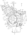
- Fig. 1: A side view of an internal combustion engine which mounts a cover structure of an internal combustion engine according to the present invention.
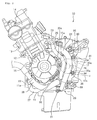
- Fig. 2: A side view of the internal combustion engine in a state that a second cover is removed from the internal combustion engine.
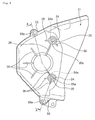
- Fig. 3: A side view of a first cover as viewed from outside as a single part.
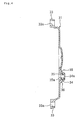
- Fig. 4: A cross-sectional view as viewed in the direction indicated by an arrow A-A in Fig. 3.
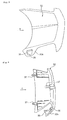
- Fig. 5: A side view of the second cover as viewed from outside as a single part.
- Fig. 6: A view as viewed in the direction indicated by an arrow B in Fig. 5.
- Fig. 7: A view as viewed in the direction indicated by an arrow C in Fig. 6.
- Hereinafter, one embodiment of a cover structure of an internal combustion engine according to the present invention is explained in detail in conjunction with attached drawings. Here, the drawings are viewed in the same direction as numerals.
- First of all, as shown in Fig. 1, an
internal combustion engine 10 includes acrankcase 11 which incorporates a transmission not shown in the drawing in the inside thereof, acylinder block 12 which is integrally formed on an upper front portion of thecrankcase 11, acylinder head 13 which is fixed to an upper end portion of thecylinder block 12, acylinder head cover 14 which closes an opening formed in an upper end portion of thecylinder head 13, agenerator cover 15 which closes an opening formed in a left-side surface of thecrankcase 11, and acooling device 20 for cooling theinternal combustion engine 10. Here,numeral 11a in the drawing indicates a crankshaft. - Further, on the left-side surface of the
crankcase 11, anoutput shaft 16 of the transmission not shown in the drawing is mounted in a projecting manner, and to theoutput shaft 16, adrive sprocket wheel 17 which constitutes a portion of a drive force transmission mechanism is connected. Further, adrive chain 17a which constitutes a portion of the drive force transmission mechanism is wound around thedrive sprocket wheel 17. - A
cooling device 20 mainly includes awater pump 21 which is arranged below thedrive sprocket wheel 17 of thecrankcase 11, anoil cooler 22 which is arranged on a front end surface of thecrankcase 11, athermostat valve 23 which is arranged on an upper end portion of thecrankcase 11, a water jacket not shown in the drawing which is formed in the inside of thecylinder block 12 and thecylinder head 13, and a radiator not shown in the drawing which is arranged in front of theinternal combustion engine 10. Thewater pump 21, theoil cooler 22, thethermostat valve 23, the water jacket not shown in the drawing, and the radiator not shown in the drawing are communicated with each other by way of respective rubber-madecooling water pipes - In this manner, the
internal combustion engine 10 of this embodiment arranges thewater pump 21 of thecooling device 20 below thedrive sprocket wheel 17 and hence, a distance between thecrankshaft 11 a and theoutput shaft 16 can be shortened compared to a conventional internal combustion engine. - Further, in this embodiment, as shown in Fig. 1 and Fig. 2, the
cooling water pipes cooling device 20 are covered with and protected by acover structure 30. Thecover structure 30 includes a sprocket wheel cover (first cover) 31 which is fixed to a left-side surface of thecrankcase 11 and is arranged to cover thedrive sprocket wheel 17, and a cooling water pipe cover (second cover) 32 which is mounted on outer surfaces of thesprocket wheel cover 31 and thegenerator cover 15 and is arranged outside thesprocket wheel cover 31 with a predetermined distance therebetween. Further, by allowing thecooling water pipes cooling device 20 to vertically pass through a space defined between thesprocket wheel cover 31 and the coolingwater pipe cover 32, thecooling water pipes water pipe cover 32. - As shown in Fig. 3 and Fig. 4, the
sprocket wheel cover 31 is formed of a plate member having a substantially trapezoidal shape as viewed in a side view. On an upper edge portion and a lower edge portion of thesprocket wheel cover 31, fixingmembers 33 havingbolt insertion holes 33a are respectively formed. Thesprocket wheel cover 31 is fixed to thecrankcase 11 by fastening thefixing members crankcase 11 using bolts (see Fig. 2). Further, twofitting projections 34 are formed on an outer surface of thesprocket wheel cover 31, and in mountingholes 34a which are formed in outer end surfaces of thefitting projections 34, rubber-madegrommets 35 having fittingholes 35a in whichengaging projections 37 of the coolingwater pipe cover 32 described later are inserted and fitted are mounted. Here, in the drawing,numeral 36 indicates reinforcing ribs for increasing the rigidity of thesprocket wheel cover 31. - As shown in Fig. 2, the
generator cover 15 forms a plate-like mounting stay 15a on a rear end portion thereof, and in a mounting hole not shown in the drawing which is formed in the mounting stay 15a, in the same manner as thefitting projection 34 of thesprocket wheel cover 31, the rubber-madegrommets 35 having fittingholes 35a in whichengaging projections 37 of the coolingwater pipe cover 32 described later are inserted and fitted are mounted. - As shown in Fig. 5 to Fig. 7, the cooling
water pipe cover 32 is formed of a plate member having a substantially trapezoidal shape as viewed in a side view, and theengaging projections 37 which are inserted and fitted in thefitting holes 35a are respectively formed on an inner surface of the coolingwater pipe cover 32 at positions corresponding to thefitting holes 35a formed in thegrommets 35 of thesprocket wheel cover 31 and thegenerator cover 15. Further, the coolingwater pipe cover 32 is mounted on thesprocket wheel cover 31 and thegenerator cover 15 by respectively inserting and fitting theengaging projections 37 thereof into thefitting holes 35a formed in thegrommets 35 of thesprocket wheel cover 31 and thegenerator cover 15. Further, the coolingwater pipe cover 32 is formed into an approximately L-shape as viewed in a plan view for forming a space defined between thesprocket wheel cover 31 and the coolingwater pipe cover 32 for allowing thecooling water pipes water pipe cover 32 is formed into an arcuate shape along an outer peripheral surface of thegenerator cover 15. - Further, on a lower end portion of the cooling
water pipe cover 32, aninclined portion 32a which is inwardly and downwardly inclined is formed. Theinclined portion 32a is provided with aguide portion 38 which guides a large-diameter breather hose (a hose having one end portion thereof exposed to the outside air) 18, and a small-diameter breather hose (a hose having one end thereof exposed to the outside air) 19 and anopening 39 which is communicated with theguide portion 38. Further, theguide portion 38 arranges the large-diameter breather hose 18 above theopening 39 and arranges the small-diameter hose 19 below theopening 39 in parallel (see Fig. 1). Here, as the breather hoses 18, 19, for example, a breather hose which discharges a blowby gas in the inside of theinternal combustion engine 10, a breather hose which discharges a fuel steam in the inside of a fuel tank not shown in the drawing, a breather hose of a reserve tank of thecooling device 20 and the like can be named. - In the
cover structure 30 of theinternal combustion engine 10 having the above-mentioned constitution, by inserting and fitting theengaging projections 37 of the coolingwater pipe cover 32 into thefitting holes 35a formed in thegrommets 35 of thesprocket wheel cover 31 and thegenerator cover 15, the coolingwater pipe cover 32 is mounted on thesprocket wheel cover 31 and thegenerator cover 15, and is arranged outside thesprocket wheel cover 31. Accordingly, the space is formed between thesprocket wheel cover 31 and the coolingwater pipe cover 32. By allowing thecooling water pipes cooling water pipes water pipe cover 32. Further, the rubber-madegrommets 36 are arranged between thesprocket wheel cover 31 and the coolingwater pipe cover 32 and between thegenerator cover 15 and the coolingwater pipe cover 32 and hence, vibrations of therespective covers - As has been explained heretofore, according to the
cover structure 30 of theinternal combustion engine 10 of this embodiment, thesecond cover 32 is arranged outside thefirst cover 31, and thecooling water pipes cooling device 20 are made to pass through the space defined between thefirst cover 31 and thesecond cover 32 and hence, even when theinternal combustion engine 10 is an internal combustion engine which shortens a distance between thecrankshaft 11a and theoutput shaft 16, it is possible to cover and protect thecooling water pipes cooling device 20 of theinternal combustion engine 10. Further, thecooling water pipes internal combustion engine 10 can be enhanced. Further, it is possible to reduce radiation sounds of theinternal combustion engine 10 with the provision of two covers, that is, with the provision of thefirst cover 31 and thesecond cover 32 and hence, the tranquility of theinternal combustion engine 10 can be enhanced. Still further, the rubber-madecooling water pipes drive sprocket wheel 17 and hence, the radiation sounds of theinternal combustion engine 10 can be further reduced. - Further, according to the
cover structure 30 of theinternal combustion engine 10 of this embodiment, thesecond cover 32 is mounted on thefirst cover 31 and theinternal combustion engine 10 by insertion and fitting thereof into thefitting holes 35a formed in thefirst cover 31 and theinternal combustion engine 10 and hence, the assembling property of thesecond cover 32 can be enhanced. Further, thesecond cover 32 is mounted on thefirst cover 31 and theinternal combustion engine 10 in a state that thesecond cover 32 strides over thefirst cover 31 and theinternal combustion engine 10 and hence, thesecond cover 32 is surely mounted on thefirst cover 31 and theinternal combustion engine 10. Further, a load which is applied to thefirst cover 31 can be reduced and hence, it is possible to realize the reduction of weight of thefirst cover 31 while ensuring the rigidity of thefirst cover 31. - Further, according to the
cover structure 30 of theinternal combustion engine 10 of this embodiment, the lower end portion of thesecond cover 32 is provided with theguide portion 38 which guides thehoses opening 39 which is communicated with theguide portion 38 and hence, it is unnecessary to additionally fix thehoses opening 39 is formed in theinclined portion 32a of thesecond cover 32 and hence, it is possible to make theopening 39 inconspicuous from the outside. Further, due to theguide portion 38, the large-diameter hose 18 can be arranged above theopening 39 and the small-diameter hose 19 can be arranged below theopening 39 and hence, it is possible to prevent the small-diameter hose 19 from being exposed to the outside as viewed in a side view thus enhancing the appearance of theinternal combustion engine 10. - The invention is directed to a cover structure of an internal combustion engine which can cover and protect a cooling water pipe of a cooling device of an internal combustion engine even when the internal combustion engine is an internal combustion engine which has a short distance between a crankshaft and an output shaft.
- The
cover structure 30 of aninternal combustion engine 10 arranges asecond cover 32 outside afirst cover 31, and coolingwater pipes cooling device 20 are made to pass through aspace defined between thefirst cover 31 and thesecond cover 32.
Claims (3)
- A cover structure (30) of an internal combustion engine (10) comprising:a first cover (31) which is arranged to cover a portion of a drive force transmission mechanism (17) connected to an output shaft (16) of an internal combustion engine (10), anda cooling device (20) for cooling the internal combustion engine (10), characterized in thata second cover (32) is arranged outside the first cover (31), anda cooling water pipe (24, 25, 26, 27) of the cooling device (20) passes through a space defined between the first cover (31) and the second cover (32).
- A cover structure (30) of an internal combustion engine (10) according to claim 1, characterized in that the second cover (32) is mounted on the internal combustion engine (10) by insertion and fitting thereof into fitting openings (35a) formed in the first cover (31) and the internal combustion engine (10).
- A cover structure (30) of an internal combustion engine (10) according to one of claim 1 or claim 2, characterized in that a lower portion of the second cover (32) is provided with a guide portion (38) which guides a hose having one end portion thereof exposed to the outside air and an opening which is communicated with the guide portion (38).
Applications Claiming Priority (1)
| Application Number | Priority Date | Filing Date | Title |
|---|---|---|---|
| JP2006230952A JP4672620B2 (en) | 2006-08-28 | 2006-08-28 | Cover structure of internal combustion engine |
Publications (3)
| Publication Number | Publication Date |
|---|---|
| EP1895138A2 true EP1895138A2 (en) | 2008-03-05 |
| EP1895138A3 EP1895138A3 (en) | 2010-09-08 |
| EP1895138B1 EP1895138B1 (en) | 2011-07-27 |
Family
ID=38481114
Family Applications (1)
| Application Number | Title | Priority Date | Filing Date |
|---|---|---|---|
| EP07012522A Ceased EP1895138B1 (en) | 2006-08-28 | 2007-06-26 | Cover structure of an internal combustion engine |
Country Status (4)
| Country | Link |
|---|---|
| US (1) | US7556013B2 (en) |
| EP (1) | EP1895138B1 (en) |
| JP (1) | JP4672620B2 (en) |
| BR (1) | BRPI0702759A (en) |
Cited By (4)
| Publication number | Priority date | Publication date | Assignee | Title |
|---|---|---|---|---|
| CN109774833A (en) * | 2017-11-15 | 2019-05-21 | 本田技研工业株式会社 | straddle vehicle |
| EP3489492A1 (en) | 2017-11-22 | 2019-05-29 | Wise Motor Works, Ltd. | Internal combustion engine, method of modifying an engine and method of running an engine |
| US10344670B2 (en) | 2013-06-05 | 2019-07-09 | Wise Motor Works, Ltd. | Internal combustion engine with paired, parallel, offset pistons |
| CN110685804A (en) * | 2018-07-06 | 2020-01-14 | 本田技研工业株式会社 | engine |
Families Citing this family (4)
| Publication number | Priority date | Publication date | Assignee | Title |
|---|---|---|---|---|
| JP6190098B2 (en) | 2012-06-14 | 2017-08-30 | 川崎重工業株式会社 | Sprocket cover for saddle riding type vehicle |
| JP6069116B2 (en) | 2013-06-26 | 2017-02-01 | 本田技研工業株式会社 | Cover structure of an internal combustion engine for a motorcycle |
| US11578647B2 (en) | 2020-03-11 | 2023-02-14 | Arctic Cat Inc. | Engine |
| CN112610354A (en) * | 2020-12-16 | 2021-04-06 | 重庆怡之驰机械有限公司 | Three-column engine box body for automobile |
Family Cites Families (5)
| Publication number | Priority date | Publication date | Assignee | Title |
|---|---|---|---|---|
| JPH0755291Y2 (en) * | 1988-03-18 | 1995-12-20 | 本田技研工業株式会社 | Protective device for engine cooling system communication pipe |
| JP3421394B2 (en) | 1993-08-20 | 2003-06-30 | 三洋電機株式会社 | Shunt |
| JP2000145452A (en) * | 1998-11-11 | 2000-05-26 | Yamaha Motor Co Ltd | Engine cooling water discharge structure |
| US6941920B1 (en) * | 2004-04-02 | 2005-09-13 | Kenneth R. Thurm | Motorcycle engine and transmission interbracing member |
| JP2007077925A (en) * | 2005-09-15 | 2007-03-29 | Kawasaki Heavy Ind Ltd | Vehicle engine |
-
2006
- 2006-08-28 JP JP2006230952A patent/JP4672620B2/en not_active Expired - Fee Related
-
2007
- 2007-06-26 EP EP07012522A patent/EP1895138B1/en not_active Ceased
- 2007-08-01 BR BRPI0702759-1A patent/BRPI0702759A/en not_active IP Right Cessation
- 2007-08-23 US US11/895,064 patent/US7556013B2/en not_active Expired - Fee Related
Cited By (5)
| Publication number | Priority date | Publication date | Assignee | Title |
|---|---|---|---|---|
| US10344670B2 (en) | 2013-06-05 | 2019-07-09 | Wise Motor Works, Ltd. | Internal combustion engine with paired, parallel, offset pistons |
| CN109774833A (en) * | 2017-11-15 | 2019-05-21 | 本田技研工业株式会社 | straddle vehicle |
| EP3489492A1 (en) | 2017-11-22 | 2019-05-29 | Wise Motor Works, Ltd. | Internal combustion engine, method of modifying an engine and method of running an engine |
| CN110685804A (en) * | 2018-07-06 | 2020-01-14 | 本田技研工业株式会社 | engine |
| US10995696B2 (en) | 2018-07-06 | 2021-05-04 | Honda Motor Co., Ltd. | Engine |
Also Published As
| Publication number | Publication date |
|---|---|
| EP1895138B1 (en) | 2011-07-27 |
| BRPI0702759A (en) | 2008-04-22 |
| JP4672620B2 (en) | 2011-04-20 |
| US7556013B2 (en) | 2009-07-07 |
| JP2008051077A (en) | 2008-03-06 |
| US20080047503A1 (en) | 2008-02-28 |
| EP1895138A3 (en) | 2010-09-08 |
Similar Documents
| Publication | Publication Date | Title |
|---|---|---|
| EP1895138B1 (en) | Cover structure of an internal combustion engine | |
| US8413754B2 (en) | Straddle vehicle | |
| EP2261492B1 (en) | Engine body, cooling-water pump arrangement structure of engine and method of forming the same | |
| EP1820947A2 (en) | Engine | |
| CN107849974B (en) | Attachment mounting structure for engine | |
| KR102222522B1 (en) | Engine device | |
| JP5806072B2 (en) | Engine oil jet structure | |
| EP2166212B1 (en) | Arrangement structure for sensor to be mounted to engine of vehicle | |
| JP5168650B2 (en) | Auxiliary structure for internal combustion engine | |
| JP7236267B2 (en) | Air-cooled engine for straddle-type vehicle | |
| JP4411637B2 (en) | Engine and vehicle | |
| JP7198628B2 (en) | straddle-type vehicle | |
| CN109026322B (en) | Cooling oil passage structure of engine | |
| US20060118088A1 (en) | Supercharged diesel engine with a common-rail injection system | |
| JP5545937B2 (en) | Motorcycle | |
| JP4079828B2 (en) | Internal combustion engine with a PCV valve | |
| JP7132071B2 (en) | internal combustion engine front cover | |
| JP4213012B2 (en) | Cooling channel structure of internal combustion engine | |
| JP4603405B2 (en) | Saddle riding vehicle | |
| JP4101619B2 (en) | Motorcycle cooling passage structure | |
| JP4123470B2 (en) | Cooling water bleeder for automobile engine | |
| JP4359012B2 (en) | Engine negative pressure pump piping structure | |
| JP7395945B2 (en) | Engine cover structure | |
| JP7393976B2 (en) | Engine cover mounting structure | |
| US20150267577A1 (en) | Oil passage structure for internal combustion engine |
Legal Events
| Date | Code | Title | Description |
|---|---|---|---|
| PUAI | Public reference made under article 153(3) epc to a published international application that has entered the european phase |
Free format text: ORIGINAL CODE: 0009012 |
|
| 17P | Request for examination filed |
Effective date: 20070626 |
|
| AK | Designated contracting states |
Kind code of ref document: A2 Designated state(s): AT BE BG CH CY CZ DE DK EE ES FI FR GB GR HU IE IS IT LI LT LU LV MC MT NL PL PT RO SE SI SK TR |
|
| AX | Request for extension of the european patent |
Extension state: AL BA HR MK YU |
|
| PUAL | Search report despatched |
Free format text: ORIGINAL CODE: 0009013 |
|
| AK | Designated contracting states |
Kind code of ref document: A3 Designated state(s): AT BE BG CH CY CZ DE DK EE ES FI FR GB GR HU IE IS IT LI LT LU LV MC MT NL PL PT RO SE SI SK TR |
|
| AX | Request for extension of the european patent |
Extension state: AL BA HR MK RS |
|
| RIC1 | Information provided on ipc code assigned before grant |
Ipc: B62J 13/00 20060101ALI20100804BHEP Ipc: F02F 7/00 20060101AFI20070922BHEP Ipc: F01P 11/04 20060101ALI20100804BHEP |
|
| GRAP | Despatch of communication of intention to grant a patent |
Free format text: ORIGINAL CODE: EPIDOSNIGR1 |
|
| RIC1 | Information provided on ipc code assigned before grant |
Ipc: F01P 11/04 20060101ALI20101006BHEP Ipc: B62J 13/00 20060101ALI20101006BHEP Ipc: F02F 7/00 20060101AFI20101006BHEP |
|
| GRAS | Grant fee paid |
Free format text: ORIGINAL CODE: EPIDOSNIGR3 |
|
| RIN1 | Information on inventor provided before grant (corrected) |
Inventor name: KUROSU, REINA Inventor name: WAKITA, NOBUTAKA Inventor name: NEGORO, MASAAKI |
|
| AKX | Designation fees paid |
Designated state(s): DE GB IT |
|
| RAP1 | Party data changed (applicant data changed or rights of an application transferred) |
Owner name: HONDA MOTOR CO., LTD. |
|
| GRAA | (expected) grant |
Free format text: ORIGINAL CODE: 0009210 |
|
| AK | Designated contracting states |
Kind code of ref document: B1 Designated state(s): DE GB IT |
|
| REG | Reference to a national code |
Ref country code: GB Ref legal event code: FG4D |
|
| REG | Reference to a national code |
Ref country code: DE Ref legal event code: R096 Ref document number: 602007016010 Country of ref document: DE Effective date: 20110915 |
|
| PLBE | No opposition filed within time limit |
Free format text: ORIGINAL CODE: 0009261 |
|
| STAA | Information on the status of an ep patent application or granted ep patent |
Free format text: STATUS: NO OPPOSITION FILED WITHIN TIME LIMIT |
|
| 26N | No opposition filed |
Effective date: 20120502 |
|
| REG | Reference to a national code |
Ref country code: DE Ref legal event code: R097 Ref document number: 602007016010 Country of ref document: DE Effective date: 20120502 |
|
| REG | Reference to a national code |
Ref country code: DE Ref legal event code: R084 Ref document number: 602007016010 Country of ref document: DE |
|
| REG | Reference to a national code |
Ref country code: GB Ref legal event code: 746 Effective date: 20150217 |
|
| REG | Reference to a national code |
Ref country code: DE Ref legal event code: R084 Ref document number: 602007016010 Country of ref document: DE Effective date: 20150210 |
|
| PGFP | Annual fee paid to national office [announced via postgrant information from national office to epo] |
Ref country code: SE Payment date: 20190611 Year of fee payment: 13 |
|
| GBPC | Gb: european patent ceased through non-payment of renewal fee |
Effective date: 20190626 |
|
| PG25 | Lapsed in a contracting state [announced via postgrant information from national office to epo] |
Ref country code: GB Free format text: LAPSE BECAUSE OF NON-PAYMENT OF DUE FEES Effective date: 20190626 |
|
| PG25 | Lapsed in a contracting state [announced via postgrant information from national office to epo] |
Ref country code: IT Free format text: LAPSE BECAUSE OF NON-PAYMENT OF DUE FEES Effective date: 20200626 |
|
| PGFP | Annual fee paid to national office [announced via postgrant information from national office to epo] |
Ref country code: DE Payment date: 20240521 Year of fee payment: 18 |
|
| REG | Reference to a national code |
Ref country code: DE Ref legal event code: R119 Ref document number: 602007016010 Country of ref document: DE |
|
| PG25 | Lapsed in a contracting state [announced via postgrant information from national office to epo] |
Ref country code: DE Free format text: LAPSE BECAUSE OF NON-PAYMENT OF DUE FEES Effective date: 20260101 |