EP1894861B1 - Automated storage and retrieval system with improved storage efficiency and method of storing articles in, and retrieving articles from the automated storage and retrieval system - Google Patents
Automated storage and retrieval system with improved storage efficiency and method of storing articles in, and retrieving articles from the automated storage and retrieval system Download PDFInfo
- Publication number
- EP1894861B1 EP1894861B1 EP07016451A EP07016451A EP1894861B1 EP 1894861 B1 EP1894861 B1 EP 1894861B1 EP 07016451 A EP07016451 A EP 07016451A EP 07016451 A EP07016451 A EP 07016451A EP 1894861 B1 EP1894861 B1 EP 1894861B1
- Authority
- EP
- European Patent Office
- Prior art keywords
- pair
- articles
- transfer apparatuses
- parts
- retrieval system
- Prior art date
- Legal status (The legal status is an assumption and is not a legal conclusion. Google has not performed a legal analysis and makes no representation as to the accuracy of the status listed.)
- Not-in-force
Links
Images



Classifications
-
- B—PERFORMING OPERATIONS; TRANSPORTING
- B65—CONVEYING; PACKING; STORING; HANDLING THIN OR FILAMENTARY MATERIAL
- B65G—TRANSPORT OR STORAGE DEVICES, e.g. CONVEYORS FOR LOADING OR TIPPING, SHOP CONVEYOR SYSTEMS OR PNEUMATIC TUBE CONVEYORS
- B65G1/00—Storing articles, individually or in orderly arrangement, in warehouses or magazines
-
- B—PERFORMING OPERATIONS; TRANSPORTING
- B65—CONVEYING; PACKING; STORING; HANDLING THIN OR FILAMENTARY MATERIAL
- B65G—TRANSPORT OR STORAGE DEVICES, e.g. CONVEYORS FOR LOADING OR TIPPING, SHOP CONVEYOR SYSTEMS OR PNEUMATIC TUBE CONVEYORS
- B65G1/00—Storing articles, individually or in orderly arrangement, in warehouses or magazines
- B65G1/02—Storage devices
- B65G1/04—Storage devices mechanical
- B65G1/0407—Storage devices mechanical using stacker cranes
-
- B—PERFORMING OPERATIONS; TRANSPORTING
- B65—CONVEYING; PACKING; STORING; HANDLING THIN OR FILAMENTARY MATERIAL
- B65G—TRANSPORT OR STORAGE DEVICES, e.g. CONVEYORS FOR LOADING OR TIPPING, SHOP CONVEYOR SYSTEMS OR PNEUMATIC TUBE CONVEYORS
- B65G1/00—Storing articles, individually or in orderly arrangement, in warehouses or magazines
- B65G1/02—Storage devices
- B65G1/04—Storage devices mechanical
-
- B—PERFORMING OPERATIONS; TRANSPORTING
- B65—CONVEYING; PACKING; STORING; HANDLING THIN OR FILAMENTARY MATERIAL
- B65G—TRANSPORT OR STORAGE DEVICES, e.g. CONVEYORS FOR LOADING OR TIPPING, SHOP CONVEYOR SYSTEMS OR PNEUMATIC TUBE CONVEYORS
- B65G1/00—Storing articles, individually or in orderly arrangement, in warehouses or magazines
- B65G1/02—Storage devices
- B65G1/04—Storage devices mechanical
- B65G1/045—Storage devices mechanical in a circular arrangement, e.g. towers
-
- B—PERFORMING OPERATIONS; TRANSPORTING
- B65—CONVEYING; PACKING; STORING; HANDLING THIN OR FILAMENTARY MATERIAL
- B65G—TRANSPORT OR STORAGE DEVICES, e.g. CONVEYORS FOR LOADING OR TIPPING, SHOP CONVEYOR SYSTEMS OR PNEUMATIC TUBE CONVEYORS
- B65G37/00—Combinations of mechanical conveyors of the same kind, or of different kinds, of interest apart from their application in particular machines or use in particular manufacturing processes
- B65G37/02—Flow-sheets for conveyor combinations in warehouses, magazines or workshops
-
- H—ELECTRICITY
- H10—SEMICONDUCTOR DEVICES; ELECTRIC SOLID-STATE DEVICES NOT OTHERWISE PROVIDED FOR
- H10P—GENERIC PROCESSES OR APPARATUS FOR THE MANUFACTURE OR TREATMENT OF DEVICES COVERED BY CLASS H10
- H10P72/00—Handling or holding of wafers, substrates or devices during manufacture or treatment thereof
- H10P72/30—Handling or holding of wafers, substrates or devices during manufacture or treatment thereof for conveying, e.g. between different workstations
- H10P72/34—Handling or holding of wafers, substrates or devices during manufacture or treatment thereof for conveying, e.g. between different workstations the wafers being stored in a carrier, involving loading and unloading
- H10P72/3404—Storage means
Definitions
- the present invention relates to an automated storage and retrieval system and a method of storing articles in, and retrieving articles from such a system according to the preamble of claims 1 and 2 respectively.
- the present invention relates to improvement of storage efficiency in the automated storage and retrieval system.
- a mast for elevating and lowering a transfer apparatus is provided to face a carousel, the carousel is rotated for orienting a desired rack opening toward the transfer apparatus, and the transfer apparatus is elevated and lowered to the height of a target shelf.
- the article can be retrieved from, and stored in an arbitrary rack opening of the carousel.
- the transfer apparatus and an elevation mechanism for the transfer apparatus are wide in the height direction, dead spaces may be created along the height direction of the rack, and the desired storage efficiency in the automated storage and retrieval system cannot be achieved.
- An object of the present invention is to improve storage efficiency in an automated storage and retrieval system. Another object of the present invention is to operate at least a pair of transfer apparatuses without interference to each other. Still another object of the present invention is to achieve further improvement of storage efficiency.
- an automated storage and retrieval system comprises at least a pair of transfer apparatuses for transfer of articles to and from a rack including a plurality of shelves.
- Each of the transfer apparatuses include a plurality of vertically overlapped parts from a proximal side to a distal side, and attached to an elevation frame.
- the elevation frame is elevated and lowered along a mast.
- the plurality of parts are arranged from the proximal side to the distal side, in an order from lower to upper parts, and in the other of the at least the pair of transfer apparatuses, the plurality of parts are arranged from the proximal side to the distal side, in an order from upper to lower parts.
- the one of the pair of transfer apparatuses is used for a shelf at the highest level, the other of the pair of transfer apparatuses is used for a shelf at the lowest level.
- a pair of elevation frames are elevated and lowered along the mast.
- the at least pair of transfer apparatuses are provided on the pair of elevation frames.
- the rack is a carousel rotatable in a horizontal direction.
- the pair of transfer apparatuses are provided respectively to face the carousel.
- a method of storing articles in, and retrieving the articles from an automated storage and retrieval system not part of the present invention comprises the steps of:
- one of at least a pair of transfer apparatuses can transfer articles from a shelf at the highest level, and the other transfer apparatus can transfer articles from the shelf at the lowest level.
- transfer in the entire area of the rack covering shelves at low positions and high positions is possible. Therefore, it is possible to provide the rack without providing dead spaces corresponding to the thickness of the transfer apparatuses in the height direction, and improvement in the efficiency of storing the articles is achieved.
- FIGS. 1 to 5 show an automated storage and retrieval system 2 according to an embodiment.
- the automated storage and retrieval system 2 is provided, e.g., in a clean room, and stores articles 13 such as semiconductor cassettes or reticle cassettes.
- a reference numeral 4 denotes a frame 4.
- a pair of carousels 6, 7 are provided in the frame 4.
- Air passages 8 are provided in the carousels 6, 7.
- a clean air or a clean gas is supplied from fan filter units 26 or the like shown in FIG. 2 .
- a rotation drive 10 is provided in each of the carousels 6, 7 to rotate the carousels 6, 7.
- Reference numerals 12 denote shelves for storing the articles 13.
- the shelves 12 are divided by a plurality of article supports.
- Each of the carousels 6, 7, can be rotated in its entirety.
- the carousels 6, 7 may be divided in a vertical direction into a plurality of upper and lower parts each including two or three shelves such that each part can be rotated independently.
- a reference numeral 14 denotes a mast provided between the pair of carousels 6, 7. Elevation frames 16 are provided on one surface and on the other surface of the mast 14, respectively, for independently elevating and lowering the elevation frames 16. A scara arm 18 is provided on one of the elevation frames 16, and a scara arm 19 is provided on the other of the elevation frames 16. Reference numerals 20 denote hands of the scara arms 18, 19. Reference numerals 22, 23 denote load ports. The scara arm 18 uses the load port 22, and the scara arm 19 uses the load port 23. Further, the scara arms 18, 19 can transfer articles to, and from both of the carousels 6, 7.
- the elevation frame 16 is elevated and lowered along a guide groove 24 provided in the mast 14.
- the elevation frame 16 is elevated and lowered synchronously with rotation of the carousel 6 or 7.
- the clean air or the clean gas is supplied to the air passages 8 in the carousels 6, 7 by the fan filter units 26.
- the carousels 6, 7 are pressurized internally for preventing entry of dust from the outside.
- the rotation drive 10 is sealed hermetically for prevention of dust emission.
- each of the scara arms 18, 19 includes joints 30, 31, 32, arms 33, 34, and a hand 20 at its distal end.
- the scara arm 18 is formed by stacking a plurality of parts from lower to upper parts, i.e., from the joint 30 to the hand 20.
- the position of the hand 20 of the scara arm 18 is higher than the proximal portion of the scara arm 18.
- parts are jointed downwardly from the joint 30 to the hand 20.
- the position of the hand 20 of the scara arm 19 is lower than the proximal portion of the scara arm 19.
- the hand 20 and the arm 34 are overlapped at the joint 32, and the arm 34 and the arm 33 are overlapped at the joint 31.
- the scara arms 18, 19 can transfer articles to and from both of the left and right carousels 6, 7. Further, the scara arms 18, 19 can transfer articles to and from the load port 22 or the load port 23.
- the joints 30, 31, 32 can be operated independently.
- FIG. 5 shows structure of the carousel 6.
- the carousel 7 has the same structure.
- the shelves 12 are divided by a plurality of article supports 36.
- a shutter 38 is provided at a rack opening of each of the article supports 36. By an opening and closing mechanism (not shown), the shutter 38 is opened and closed synchronously with operation of the hand 20.
- the clean air or the like from the fan filter units 26 is supplied to the respective shelves 12 through the air passages 8.
- the scara arms 18, 19 can perform transfer operation to, and from the common carousel 6 or the like at the same time.
- the other shelves which are not used in the current transfer operation can be rotated independently in preparation for the next transfer operation.
- each of the carousels 6, 7 may be rotated in its entirety.
- FIG. 6 shows an automated storage and retrieval system 42 according to a modified embodiment.
- the features of the automated storage and retrieval system 42 are the same as those shown in FIGS. 1 to 5 .
- masts 44, 45 are provided additionally at both of the left and right ends, and a pair of elevation frames 16 are provided for each of the masts 44, 45.
- Scara arms 18, 19 are provided for transfer of articles to and from the outside through the load ports 46, 47. As a result, in total, six scara arms 18, 19 can be used for the pair of carousels 6, 7. In this manner, further reduction in the cycle time is achieved.
- the transfer means is not limited to the scara arms 18, 19, as long as it has a plurality of parts, and the parts are overlapped with each other.
- shelves in one level in the height direction are only used by the scara arm 18 or the scara arm 19.
- shelves in two or more levels in the height direction are only used by the scara arm 18 or the scara arm 19.
Landscapes
- Engineering & Computer Science (AREA)
- Mechanical Engineering (AREA)
- Warehouses Or Storage Devices (AREA)
- Container, Conveyance, Adherence, Positioning, Of Wafer (AREA)
Description
- The present invention relates to an automated storage and retrieval system and a method of storing articles in, and retrieving articles from such a system according to the preamble of
claims 1 and 2 respectively. In particular, the present invention relates to improvement of storage efficiency in the automated storage and retrieval system. - In a known technique for the automated storage and retrieval system (
Japanese Patent Publication No. 1992-292312
From the documentUS-A-5 362 192 an automated data storage library is known which includes a plurality of storage cells for holding storage media cartridges therein this document discloses an automated storage system and a method of storing articles according to the preamble ofclaims 1 and 2 respectively. A picker mechanism is positioned for accessing and transporting the storage media cartridges between the storage cells. At least two cartridge grippers are mounted on the picker mechanism for selective movement along respective gripper paths.
Prior art documentJP-A-11-208818 - An object of the present invention is to improve storage efficiency in an automated storage and retrieval system.
Another object of the present invention is to operate at least a pair of transfer apparatuses without interference to each other.
Still another object of the present invention is to achieve further improvement of storage efficiency. - These and other objects are solved by an automated storage and retrieval system having the features as set forth in claim 1. The mentioned problems are also solved by a method for storing and retrieving articles as defined in
claim 2. - According to the present invention, an automated storage and retrieval system comprises at least a pair of transfer apparatuses for transfer of articles to and from a rack including a plurality of shelves. Each of the transfer apparatuses include a plurality of vertically overlapped parts from a proximal side to a distal side, and attached to an elevation frame. The elevation frame is elevated and lowered along a mast.
In one of the at least the pair of transfer apparatuses, the plurality of parts are arranged from the proximal side to the distal side, in an order from lower to upper parts, and in the other of the at least the pair of transfer apparatuses, the plurality of parts are arranged from the proximal side to the distal side, in an order from upper to lower parts.
The one of the pair of transfer apparatuses is used for a shelf at the highest level, the other of the pair of transfer apparatuses is used for a shelf at the lowest level.
A pair of elevation frames are elevated and lowered along the mast. The at least pair of transfer apparatuses are provided on the pair of elevation frames.
The rack is a carousel rotatable in a horizontal direction. The pair of transfer apparatuses are provided respectively to face the carousel. - Further, in a method of storing articles in, and retrieving the articles from an automated storage and retrieval system not part of the present invention, described are the steps of:
- providing at least a pair of transfer apparatuses on at least one elevation frame being elevated and lowered along a mast, in one of the at least the pair of transfer apparatuses, a plurality of parts being arranged from a proximal side to a distal side, in an order from lower to upper parts, and in the other of the at least the pair of transfer apparatuses, a plurality of parts being arranged from the proximal side to the distal side, in an order from upper to lower parts;
- providing at least one rack including a plurality of shelves at a plurality of levels in a height direction; and
- storing the articles in, and retrieving the articles from the rack using the one of the pair of transfer apparatuses for a shelf of the rack at the highest level, and using the other of the pair of the transfer apparatuses for a shelf of the rack at the lowest level.
- A method of storing articles in, and retrieving the articles from an automated storage and retrieval system not part of the present invention comprises the steps of:
- providing a pair of elevation frames for a mast;
- providing transfer apparatuses on the pair of elevation frames, respectively;
- in one of the pair of transfer apparatuses, arranging a plurality of parts from a proximal side to a distal side, in an order from lower to upper parts, and in the other of the pair of transfer apparatuses, arranging a plurality of parts from the proximal side to the distal side, in an order from upper to lower parts;
- providing a pair of racks including a plurality of shelves at a plurality of levels in a height direction on both sides of the mast;
- storing the articles in, and retrieving the articles from a shelf at the highest level, of each of the racks using the one of the pair of transfer apparatuses, and storing the articles in, and retrieving the articles from a shelf at the lowest level, of each of the racks using the other of the pair of transfer apparatuses.
- In the present invention, one of at least a pair of transfer apparatuses can transfer articles from a shelf at the highest level, and the other transfer apparatus can transfer articles from the shelf at the lowest level. Thus, transfer in the entire area of the rack covering shelves at low positions and high positions is possible. Therefore, it is possible to provide the rack without providing dead spaces corresponding to the thickness of the transfer apparatuses in the height direction, and improvement in the efficiency of storing the articles is achieved.
- When using the carousels, since the transfer apparatuses do not interfere with each other, improvement in the operating efficiency of the transfer apparatuses is achieved, and the cycle time in storage in, and retrieval from the storage and retrieval system is reduced advantageously.
- By elevating and lowering a pair of elevation frames along the mast, it is possible to minimize the space for providing the mast or the like. Since the required space is minimized, storage efficiency is improved, and it is possible to increase the strength of the mast advantageously.
-
- [
FIG. 1 ]
FIG. 1 is a plan view schematically showing an automated storage and retrieval system according to an embodiment. - [
FIG. 2 ]
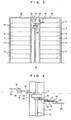
FIG. 2 is a side view schematically showing the automated storage and retrieval system according to the embodiment, taken along a line II-II inFIG. 1 . - [
FIG. 3 ]
FIG. 3 is a side view schematically showing the automated storage and retrieval system according to the embodiment, taken along a line III-III inFIG. 1 . - [
FIG. 4 ]
FIG. 4 is a view showing the relationship between upper and lower arms according to the embodiment. The lower arm is denoted by a solid line, and an upper arm is denoted by a chain line. - [
FIG. 5 ]
FIG. 5 is a cross sectional view in a horizontal direction, showing structure of a carousel according to the embodiment. - [
FIG. 6 ]
FIG. 6 is a plan view schematically showing an automated storage and retrieval system according to a modified embodiment. - 2, 42:
- automated storage and retrieval system
- 4:
- frame
- 6, 7:
- carousel
- 8:
- air passage
- 10:
- rotation drive
- 12:
- shelf
- 13:
- article
- 14:
- mast
- 16:
- elevation frame
- 18, 19:
- scara arm
- 20:
- hand
- 22, 23:
- load port
- 24:
- guide groove
- 26:
- fan filter unit
- 30 to 32:
- joint
- 33, 34:
- arm
- 36:
- article support
- 38:
- shutter
- 44, 45:
- mast
- 46, 47:
- load port
-
FIGS. 1 to 5 show an automated storage andretrieval system 2 according to an embodiment. The automated storage andretrieval system 2 is provided, e.g., in a clean room, and storesarticles 13 such as semiconductor cassettes or reticle cassettes. Areference numeral 4 denotes aframe 4. For example, a pair ofcarousels frame 4.Air passages 8 are provided in thecarousels fan filter units 26 or the like shown inFIG. 2 . Further, preferably, arotation drive 10 is provided in each of thecarousels carousels Reference numerals 12 denote shelves for storing thearticles 13. Theshelves 12 are divided by a plurality of article supports. Each of thecarousels carousels - A
reference numeral 14 denotes a mast provided between the pair ofcarousels mast 14, respectively, for independently elevating and lowering the elevation frames 16. Ascara arm 18 is provided on one of the elevation frames 16, and ascara arm 19 is provided on the other of the elevation frames 16.Reference numerals 20 denote hands of thescara arms Reference numerals scara arm 18 uses theload port 22, and thescara arm 19 uses theload port 23. Further, thescara arms carousels - As shown in
FIGS. 2 and3 , theelevation frame 16 is elevated and lowered along aguide groove 24 provided in themast 14. Theelevation frame 16 is elevated and lowered synchronously with rotation of thecarousel air passages 8 in thecarousels fan filter units 26. Thecarousels - As shown in
FIG. 4 , each of thescara arms joints arms hand 20 at its distal end. Thescara arm 18 is formed by stacking a plurality of parts from lower to upper parts, i.e., from the joint 30 to thehand 20. The position of thehand 20 of thescara arm 18 is higher than the proximal portion of thescara arm 18. In thescara arm 19, parts are jointed downwardly from the joint 30 to thehand 20. The position of thehand 20 of thescara arm 19 is lower than the proximal portion of thescara arm 19. Thehand 20 and thearm 34 are overlapped at the joint 32, and thearm 34 and thearm 33 are overlapped at the joint 31. Thescara arms right carousels scara arms load port 22 or theload port 23. For this purpose, thejoints -
FIG. 5 shows structure of thecarousel 6. Thecarousel 7 has the same structure. Theshelves 12 are divided by a plurality of article supports 36. Ashutter 38 is provided at a rack opening of each of the article supports 36. By an opening and closing mechanism (not shown), theshutter 38 is opened and closed synchronously with operation of thehand 20. In thecarousels fan filter units 26 is supplied to therespective shelves 12 through theair passages 8. In the case where theshelves 12 are divided into groups of two shelves, or three shelves, and each group can be rotated independently, thescara arms common carousel 6 or the like at the same time. During transfer operation by thescara arms carousels - Advantages of the embodiment will be described.
- 1) The
scara arm 19 can transfer articles to and from shelves at the lowest level of thecarousels scara arm 18 can transfer articles to and from shelves at the highest level of thecarousels scara arms shelves 12 can be provided over the entire height of the automated storage andretrieval system 2. Improvement of efficiency for storing thearticles 13 is achieved. - 2) A pair of the
scara arms carousels carousels - 3) By elevating and lowering a pair of the elevation frames 16 using the
common mast 14, the required space is further reduced. Therefore, improvement of storage efficiency is achieved, and it is possible to use a mast having high rigidity as themast 14. - 4) By supplying the clean air or the clean gas into the
carousels articles 13 in a clean environment. -
FIG. 6 shows an automated storage andretrieval system 42 according to a modified embodiment. Unless specifically noted, the features of the automated storage andretrieval system 42 are the same as those shown inFIGS. 1 to 5 . In the automated storage andretrieval system 42,masts masts Scara arms load ports scara arms carousels - Further, the transfer means is not limited to the
scara arms scara arm 18 or thescara arm 19. Depending on the thickness of thescara arms scara arm 18 or thescara arm 19.
Claims (2)
- An automated storage and retrieval system (2, 42) comprising at least a pair of transfer apparatuses (18, 19) for transfer of articles (13) to and from a rack (6, 7) including a plurality of shelves (12), the transfer apparatuses (18, 19) each including a plurality of vertically overlapped parts (30-34, 20) from a proximal side to a distal side, and attached to an elevation frame (16), the elevation frame being elevated and lowered along a mast (14; 44, 45);
in one (18) of said at least the pair of transfer apparatuses (18, 19), the plurality of parts (30-34, 20) being arranged from the proximal side to the distal side, in an order from lower to upper parts, and in the other (19) of the at least the pair of transfer apparatuses (18, 19), the plurality of parts (30-34, 20) being arranged from the proximal side to the distal side, in an order from upper to lower parts; and
said one (18) of the pair of transfer apparatuses (18, 19) being used for a shelf (12) at the highest level, said the other (19) of the pair of transfer apparatuses (18, 19) being used for a shelf (12) at the lowest level, characterized by
a pair of elevation frames (16), the elevation frames (16) being elevated and lowered independently along the mast (14), said at least the pair of transfer apparatuses (18, 19) being provided on the pair of elevation frames (16) respectively,
wherein the rack (6, 7) being a carousel rotatable in a horizontal direction, the pair of transfer apparatuses (18, 19) being provided respectively to face the carousel, and
wherein the plurality of shelves (12) are at a plurality of levels in a height direction on the carousel (6,7) and being divided into plural groups and each group rotating independently of other groups. - A method of storing articles (13) in, and retrieving the articles (13) from an automated storage and retrieval system (2, 42), the method comprising the steps of:providing a pair of transfer apparatuses (18, 19);in one (18) of the pair of transfer apparatuses (18, 19), arranging a plurality of parts (30-34, 20) from a proximal side to a distal side, in an order from lower to upper parts, and in the other (19) of the pair of transfer apparatuses (18, 19), arranging a plurality of parts (30-34, 20) from the proximal side to the distal side, in an order from upper to lower parts;providing a pair of racks (6, 7) each including a plurality of shelves (12) at a plurality of levels in a height direction on both sides of a mast (14; 44, 45); characterized byproviding a pair of elevation frames (16) for the mast (14; 44, 45) the elevation frames (16) elevating and lowering independently;providing the pair of transfer apparatuses (18, 19) on the pair of elevation frames (16) respectively;storing the articles (13) in, and retrieving the articles (13) from a shelf (12) at the highest level, of each of the racks (6, 7) using the one of the pair of transfer apparatuses (18, 19), and storing the articles (13) in, and retrieving the articles (13) from a shelf (12) at the lowest level, of each of the racks (6, 7) using the other of the pair of transfer apparatuses (18, 19),the pair of racks (6, 7) being carousels rotatable in a horizontal direction, andwherein the plurality of shelves (12) are at a plurality of levels in a height direction on the carousel (6, 7) and being devided into plural groups and each group rotating independently of other groups.
Applications Claiming Priority (1)
| Application Number | Priority Date | Filing Date | Title |
|---|---|---|---|
| JP2006238584A JP2008056474A (en) | 2006-09-04 | 2006-09-04 | Automatic warehouse |
Publications (2)
| Publication Number | Publication Date |
|---|---|
| EP1894861A1 EP1894861A1 (en) | 2008-03-05 |
| EP1894861B1 true EP1894861B1 (en) | 2011-02-16 |
Family
ID=38724518
Family Applications (1)
| Application Number | Title | Priority Date | Filing Date |
|---|---|---|---|
| EP07016451A Not-in-force EP1894861B1 (en) | 2006-09-04 | 2007-08-22 | Automated storage and retrieval system with improved storage efficiency and method of storing articles in, and retrieving articles from the automated storage and retrieval system |
Country Status (7)
| Country | Link |
|---|---|
| US (1) | US7887279B2 (en) |
| EP (1) | EP1894861B1 (en) |
| JP (1) | JP2008056474A (en) |
| KR (1) | KR20080021570A (en) |
| CN (1) | CN101139037A (en) |
| DE (1) | DE602007012494D1 (en) |
| TW (1) | TW200819368A (en) |
Cited By (1)
| Publication number | Priority date | Publication date | Assignee | Title |
|---|---|---|---|---|
| WO2019017910A1 (en) * | 2017-07-18 | 2019-01-24 | Hewlett-Packard Development Company, L.P. | Reagent fluid cartridge storage devices |
Families Citing this family (16)
| Publication number | Priority date | Publication date | Assignee | Title |
|---|---|---|---|---|
| EP2383209A4 (en) * | 2009-01-23 | 2014-01-15 | Murata Machinery Ltd | AUTOMATED WAREHOUSE |
| KR101109752B1 (en) * | 2009-10-14 | 2012-03-15 | 주식회사 코넥 | Turntable |
| WO2013071491A1 (en) * | 2011-11-14 | 2013-05-23 | 深圳市华星光电技术有限公司 | Spatial three-dimensional online conveyor system |
| US20140079518A1 (en) * | 2012-09-19 | 2014-03-20 | Shenzhen China Star Optoelectronics Technology Co., Ltd. | Stacking Crane System and the Stacking Crane Thereof |
| CN104443977B (en) * | 2014-09-23 | 2016-06-29 | 华北电力大学 | A kind of rotary automatic access goods device and method |
| CN105366254B (en) * | 2015-11-14 | 2019-05-07 | 合肥天之通电子商务有限公司 | A kind of polymorphic type vegetables and fruits goods sorting system |
| TWI588074B (en) * | 2016-10-24 | 2017-06-21 | Automatic material storage machine for storage equipment | |
| CA3083095A1 (en) | 2017-11-21 | 2019-05-31 | Fulfil Solutions, Inc. | Product handling and packaging system |
| JP7037352B2 (en) * | 2017-12-26 | 2022-03-16 | 川崎重工業株式会社 | Transport system |
| JP6704423B2 (en) * | 2018-01-17 | 2020-06-03 | 株式会社Kokusai Electric | Substrate processing apparatus, semiconductor device manufacturing method, and program |
| TWI697448B (en) * | 2018-09-10 | 2020-07-01 | 迅得機械股份有限公司 | Wafer box storage system |
| US11227782B2 (en) * | 2019-07-31 | 2022-01-18 | Asm Ip Holding B.V. | Vertical batch furnace assembly |
| CN112320188A (en) * | 2020-11-26 | 2021-02-05 | 深圳市同富信息技术有限公司 | Intelligent warehousing device for intelligent factory based on automatic classification |
| CN113200268B (en) * | 2021-03-28 | 2022-06-24 | 大连廉川人工智能技术研发有限公司 | Imitation biological material conveyor robot |
| CN117326252B (en) * | 2023-10-12 | 2025-11-14 | 环旭电子股份有限公司 | A rotating automated warehouse, a clamping method, a warehouse location calibration method and system |
| EP4564414A1 (en) * | 2023-11-30 | 2025-06-04 | Brooks Automation (Germany) GmbH | Stocker for storing a semiconductor fabrication article |
Family Cites Families (17)
| Publication number | Priority date | Publication date | Assignee | Title |
|---|---|---|---|---|
| US2667983A (en) * | 1948-10-20 | 1954-02-02 | Roy O Billings | Apparatus for handling automobiles |
| DE2519864C3 (en) * | 1975-05-03 | 1979-06-13 | Uwe 4600 Dortmund Kochanneck | Mobile shelving system |
| JPS5699103A (en) | 1980-01-14 | 1981-08-10 | Hitachi Ltd | Automatic warehouse installation |
| JPS6160505A (en) | 1984-09-03 | 1986-03-28 | Hitachi Ltd | stacker crane |
| JPS62194605U (en) | 1986-05-30 | 1987-12-10 | ||
| DE3922964A1 (en) * | 1989-07-12 | 1991-01-17 | Keuro Maschinenbau Gmbh | METHOD AND DEVICE FOR REMOVING AND STORING CASSETTES CONTAINING RODS OR PLATE-SHAPED MATERIAL FROM A SHELVING STORAGE |
| AT396586B (en) * | 1989-07-19 | 1993-10-25 | Lager Technik Gmbh | RAIL-DRIVEN VEHICLE FOR THE OPERATION OF HIGH RACKS |
| JPH04292312A (en) * | 1991-03-19 | 1992-10-16 | Murata Mach Ltd | Clean warehouse |
| JPH04338006A (en) * | 1991-05-13 | 1992-11-25 | Daifuku Co Ltd | Load transferring device |
| CH684203A5 (en) * | 1993-07-15 | 1994-07-29 | Jacek Wagner | Cylindrical parking building having a central cylindrical inner shaft and car-conveying apparatuses which are independent of one another |
| US5362192A (en) | 1993-09-24 | 1994-11-08 | International Business Machines Corporation | Automated data storage library with single input double gripper mechanism |
| JPH07242306A (en) | 1994-03-04 | 1995-09-19 | Tadashi Shimizu | Transfer machine for article stock rack |
| JP3892494B2 (en) | 1996-01-26 | 2007-03-14 | 東京エレクトロン株式会社 | Substrate transfer device |
| US6224313B1 (en) * | 1997-04-01 | 2001-05-01 | Murata Kikai Kabushiki Kaisha | Automatic warehouse |
| US6390756B1 (en) * | 1997-10-29 | 2002-05-21 | Siemens Dematic Postal Automation, L.P. | Transfer of cartridges containing flat articles |
| JPH11208818A (en) | 1998-01-29 | 1999-08-03 | Advanced Display Inc | Storage warehouse |
| DE10136354B4 (en) * | 2001-07-26 | 2010-06-17 | Knapp Ag | Method and plant for picking with a container rack and associated storage and retrieval unit |
-
2006
- 2006-09-04 JP JP2006238584A patent/JP2008056474A/en active Pending
-
2007
- 2007-08-22 EP EP07016451A patent/EP1894861B1/en not_active Not-in-force
- 2007-08-22 DE DE602007012494T patent/DE602007012494D1/en active Active
- 2007-08-31 US US11/896,316 patent/US7887279B2/en not_active Expired - Fee Related
- 2007-08-31 TW TW096132506A patent/TW200819368A/en unknown
- 2007-09-04 CN CNA2007101482745A patent/CN101139037A/en active Pending
- 2007-09-04 KR KR1020070089448A patent/KR20080021570A/en not_active Withdrawn
Cited By (1)
| Publication number | Priority date | Publication date | Assignee | Title |
|---|---|---|---|---|
| WO2019017910A1 (en) * | 2017-07-18 | 2019-01-24 | Hewlett-Packard Development Company, L.P. | Reagent fluid cartridge storage devices |
Also Published As
| Publication number | Publication date |
|---|---|
| DE602007012494D1 (en) | 2011-03-31 |
| US20080124201A1 (en) | 2008-05-29 |
| TW200819368A (en) | 2008-05-01 |
| EP1894861A1 (en) | 2008-03-05 |
| KR20080021570A (en) | 2008-03-07 |
| US7887279B2 (en) | 2011-02-15 |
| JP2008056474A (en) | 2008-03-13 |
| CN101139037A (en) | 2008-03-12 |
Similar Documents
| Publication | Publication Date | Title |
|---|---|---|
| US7887279B2 (en) | Automated storage and retrieval system with improved storage efficiency and method of storing articles in, and retrieving articles from the automated storage and retrieval system | |
| JP7102400B2 (en) | Methods and equipment for retrieving units from storage systems | |
| JP7735303B2 (en) | Automated storage system with storage tower in isolation enclosure | |
| US11981505B2 (en) | Storage system | |
| JP4283559B2 (en) | Conveying apparatus, vacuum processing apparatus, and atmospheric pressure conveying apparatus | |
| US8718815B2 (en) | Automated warehouse system | |
| US12617619B2 (en) | Container handling module | |
| US6048162A (en) | Wafer handler for multi-station tool | |
| US20230089597A1 (en) | System and method for automated wafer carrier handling | |
| CN112262083B (en) | Conveyor system having an access point and method of accessing an access point of a conveyor system | |
| US9834378B2 (en) | Loader and buffer for reduced lot size | |
| US6379096B1 (en) | Buffer storage system | |
| JP2024513081A5 (en) | ||
| US6868049B2 (en) | Method and system for accessing multiple rows of media objects in an automated storage library using a single track robotic mechanism | |
| EP1196338B1 (en) | Storage and retrieval system | |
| NO346798B1 (en) | An assembly and a method for handling goods holders and an automated storage and retrieval system comprising said assembly | |
| CN100522465C (en) | Tool shelf magazine | |
| CN220250395U (en) | Biological sample ice chest | |
| CN119103778A (en) | Biological sample freezer | |
| JPH0252808A (en) | Method and device for transferring loads on a rotating rack | |
| JP2504970B2 (en) | Touring tower | |
| TWI764849B (en) | cryogenic storage system | |
| JP2014084218A (en) | Multi-stage mobile rack device | |
| US20240399377A1 (en) | Large-Scale Biological Sample Storage | |
| KR101254619B1 (en) | apparatus for transferring glass substrates And transferring method using the same |
Legal Events
| Date | Code | Title | Description |
|---|---|---|---|
| PUAI | Public reference made under article 153(3) epc to a published international application that has entered the european phase |
Free format text: ORIGINAL CODE: 0009012 |
|
| AK | Designated contracting states |
Kind code of ref document: A1 Designated state(s): AT BE BG CH CY CZ DE DK EE ES FI FR GB GR HU IE IS IT LI LT LU LV MC MT NL PL PT RO SE SI SK TR |
|
| AX | Request for extension of the european patent |
Extension state: AL BA HR MK YU |
|
| 17P | Request for examination filed |
Effective date: 20080714 |
|
| AKX | Designation fees paid |
Designated state(s): DE FR IT |
|
| 17Q | First examination report despatched |
Effective date: 20090504 |
|
| GRAP | Despatch of communication of intention to grant a patent |
Free format text: ORIGINAL CODE: EPIDOSNIGR1 |
|
| GRAS | Grant fee paid |
Free format text: ORIGINAL CODE: EPIDOSNIGR3 |
|
| GRAA | (expected) grant |
Free format text: ORIGINAL CODE: 0009210 |
|
| AK | Designated contracting states |
Kind code of ref document: B1 Designated state(s): DE FR IT |
|
| REF | Corresponds to: |
Ref document number: 602007012494 Country of ref document: DE Date of ref document: 20110331 Kind code of ref document: P |
|
| REG | Reference to a national code |
Ref country code: DE Ref legal event code: R096 Ref document number: 602007012494 Country of ref document: DE Effective date: 20110331 |
|
| PGFP | Annual fee paid to national office [announced via postgrant information from national office to epo] |
Ref country code: DE Payment date: 20110823 Year of fee payment: 5 |
|
| PLBE | No opposition filed within time limit |
Free format text: ORIGINAL CODE: 0009261 |
|
| STAA | Information on the status of an ep patent application or granted ep patent |
Free format text: STATUS: NO OPPOSITION FILED WITHIN TIME LIMIT |
|
| 26N | No opposition filed |
Effective date: 20111117 |
|
| REG | Reference to a national code |
Ref country code: DE Ref legal event code: R097 Ref document number: 602007012494 Country of ref document: DE Effective date: 20111117 |
|
| REG | Reference to a national code |
Ref country code: FR Ref legal event code: ST Effective date: 20120430 |
|
| PG25 | Lapsed in a contracting state [announced via postgrant information from national office to epo] |
Ref country code: IT Free format text: LAPSE BECAUSE OF NON-PAYMENT OF DUE FEES Effective date: 20110822 |
|
| PG25 | Lapsed in a contracting state [announced via postgrant information from national office to epo] |
Ref country code: FR Free format text: LAPSE BECAUSE OF NON-PAYMENT OF DUE FEES Effective date: 20110831 |
|
| PG25 | Lapsed in a contracting state [announced via postgrant information from national office to epo] |
Ref country code: DE Free format text: LAPSE BECAUSE OF NON-PAYMENT OF DUE FEES Effective date: 20130301 |
|
| REG | Reference to a national code |
Ref country code: DE Ref legal event code: R119 Ref document number: 602007012494 Country of ref document: DE Effective date: 20130301 |