EP1894805A2 - Hybrid vehicle control apparatus - Google Patents
Hybrid vehicle control apparatus Download PDFInfo
- Publication number
- EP1894805A2 EP1894805A2 EP07114948A EP07114948A EP1894805A2 EP 1894805 A2 EP1894805 A2 EP 1894805A2 EP 07114948 A EP07114948 A EP 07114948A EP 07114948 A EP07114948 A EP 07114948A EP 1894805 A2 EP1894805 A2 EP 1894805A2
- Authority
- EP
- European Patent Office
- Prior art keywords
- clutch
- rotational speed
- control
- motor
- torque
- Prior art date
- Legal status (The legal status is an assumption and is not a legal conclusion. Google has not performed a legal analysis and makes no representation as to the accuracy of the status listed.)
- Granted
Links
Images





Classifications
-
- B—PERFORMING OPERATIONS; TRANSPORTING
- B60—VEHICLES IN GENERAL
- B60K—ARRANGEMENT OR MOUNTING OF PROPULSION UNITS OR OF TRANSMISSIONS IN VEHICLES; ARRANGEMENT OR MOUNTING OF PLURAL DIVERSE PRIME-MOVERS IN VEHICLES; AUXILIARY DRIVES FOR VEHICLES; INSTRUMENTATION OR DASHBOARDS FOR VEHICLES; ARRANGEMENTS IN CONNECTION WITH COOLING, AIR INTAKE, GAS EXHAUST OR FUEL SUPPLY OF PROPULSION UNITS IN VEHICLES
- B60K6/00—Arrangement or mounting of plural diverse prime-movers for mutual or common propulsion, e.g. hybrid propulsion systems comprising electric motors and internal combustion engines
- B60K6/20—Arrangement or mounting of plural diverse prime-movers for mutual or common propulsion, e.g. hybrid propulsion systems comprising electric motors and internal combustion engines the prime-movers consisting of electric motors and internal combustion engines, e.g. HEVs
- B60K6/22—Arrangement or mounting of plural diverse prime-movers for mutual or common propulsion, e.g. hybrid propulsion systems comprising electric motors and internal combustion engines the prime-movers consisting of electric motors and internal combustion engines, e.g. HEVs characterised by apparatus, components or means specially adapted for HEVs
- B60K6/36—Arrangement or mounting of plural diverse prime-movers for mutual or common propulsion, e.g. hybrid propulsion systems comprising electric motors and internal combustion engines the prime-movers consisting of electric motors and internal combustion engines, e.g. HEVs characterised by apparatus, components or means specially adapted for HEVs characterised by the transmission gearings
-
- B—PERFORMING OPERATIONS; TRANSPORTING
- B60—VEHICLES IN GENERAL
- B60W—CONJOINT CONTROL OF VEHICLE SUB-UNITS OF DIFFERENT TYPE OR DIFFERENT FUNCTION; CONTROL SYSTEMS SPECIALLY ADAPTED FOR HYBRID VEHICLES; ROAD VEHICLE DRIVE CONTROL SYSTEMS FOR PURPOSES NOT RELATED TO THE CONTROL OF A PARTICULAR SUB-UNIT
- B60W20/00—Control systems specially adapted for hybrid vehicles
- B60W20/40—Controlling the engagement or disengagement of prime movers, e.g. for transition between prime movers
-
- B—PERFORMING OPERATIONS; TRANSPORTING
- B60—VEHICLES IN GENERAL
- B60K—ARRANGEMENT OR MOUNTING OF PROPULSION UNITS OR OF TRANSMISSIONS IN VEHICLES; ARRANGEMENT OR MOUNTING OF PLURAL DIVERSE PRIME-MOVERS IN VEHICLES; AUXILIARY DRIVES FOR VEHICLES; INSTRUMENTATION OR DASHBOARDS FOR VEHICLES; ARRANGEMENTS IN CONNECTION WITH COOLING, AIR INTAKE, GAS EXHAUST OR FUEL SUPPLY OF PROPULSION UNITS IN VEHICLES
- B60K6/00—Arrangement or mounting of plural diverse prime-movers for mutual or common propulsion, e.g. hybrid propulsion systems comprising electric motors and internal combustion engines
- B60K6/20—Arrangement or mounting of plural diverse prime-movers for mutual or common propulsion, e.g. hybrid propulsion systems comprising electric motors and internal combustion engines the prime-movers consisting of electric motors and internal combustion engines, e.g. HEVs
- B60K6/22—Arrangement or mounting of plural diverse prime-movers for mutual or common propulsion, e.g. hybrid propulsion systems comprising electric motors and internal combustion engines the prime-movers consisting of electric motors and internal combustion engines, e.g. HEVs characterised by apparatus, components or means specially adapted for HEVs
- B60K6/38—Arrangement or mounting of plural diverse prime-movers for mutual or common propulsion, e.g. hybrid propulsion systems comprising electric motors and internal combustion engines the prime-movers consisting of electric motors and internal combustion engines, e.g. HEVs characterised by apparatus, components or means specially adapted for HEVs characterised by the driveline clutches
- B60K6/383—One-way clutches or freewheel devices
-
- B—PERFORMING OPERATIONS; TRANSPORTING
- B60—VEHICLES IN GENERAL
- B60K—ARRANGEMENT OR MOUNTING OF PROPULSION UNITS OR OF TRANSMISSIONS IN VEHICLES; ARRANGEMENT OR MOUNTING OF PLURAL DIVERSE PRIME-MOVERS IN VEHICLES; AUXILIARY DRIVES FOR VEHICLES; INSTRUMENTATION OR DASHBOARDS FOR VEHICLES; ARRANGEMENTS IN CONNECTION WITH COOLING, AIR INTAKE, GAS EXHAUST OR FUEL SUPPLY OF PROPULSION UNITS IN VEHICLES
- B60K6/00—Arrangement or mounting of plural diverse prime-movers for mutual or common propulsion, e.g. hybrid propulsion systems comprising electric motors and internal combustion engines
- B60K6/20—Arrangement or mounting of plural diverse prime-movers for mutual or common propulsion, e.g. hybrid propulsion systems comprising electric motors and internal combustion engines the prime-movers consisting of electric motors and internal combustion engines, e.g. HEVs
- B60K6/42—Arrangement or mounting of plural diverse prime-movers for mutual or common propulsion, e.g. hybrid propulsion systems comprising electric motors and internal combustion engines the prime-movers consisting of electric motors and internal combustion engines, e.g. HEVs characterised by the architecture of the hybrid electric vehicle
- B60K6/48—Parallel type
-
- B—PERFORMING OPERATIONS; TRANSPORTING
- B60—VEHICLES IN GENERAL
- B60K—ARRANGEMENT OR MOUNTING OF PROPULSION UNITS OR OF TRANSMISSIONS IN VEHICLES; ARRANGEMENT OR MOUNTING OF PLURAL DIVERSE PRIME-MOVERS IN VEHICLES; AUXILIARY DRIVES FOR VEHICLES; INSTRUMENTATION OR DASHBOARDS FOR VEHICLES; ARRANGEMENTS IN CONNECTION WITH COOLING, AIR INTAKE, GAS EXHAUST OR FUEL SUPPLY OF PROPULSION UNITS IN VEHICLES
- B60K6/00—Arrangement or mounting of plural diverse prime-movers for mutual or common propulsion, e.g. hybrid propulsion systems comprising electric motors and internal combustion engines
- B60K6/20—Arrangement or mounting of plural diverse prime-movers for mutual or common propulsion, e.g. hybrid propulsion systems comprising electric motors and internal combustion engines the prime-movers consisting of electric motors and internal combustion engines, e.g. HEVs
- B60K6/50—Architecture of the driveline characterised by arrangement or kind of transmission units
- B60K6/54—Transmission for changing ratio
- B60K6/547—Transmission for changing ratio the transmission being a stepped gearing
-
- B—PERFORMING OPERATIONS; TRANSPORTING
- B60—VEHICLES IN GENERAL
- B60W—CONJOINT CONTROL OF VEHICLE SUB-UNITS OF DIFFERENT TYPE OR DIFFERENT FUNCTION; CONTROL SYSTEMS SPECIALLY ADAPTED FOR HYBRID VEHICLES; ROAD VEHICLE DRIVE CONTROL SYSTEMS FOR PURPOSES NOT RELATED TO THE CONTROL OF A PARTICULAR SUB-UNIT
- B60W10/00—Conjoint control of vehicle sub-units of different type or different function
- B60W10/02—Conjoint control of vehicle sub-units of different type or different function including control of driveline clutches
-
- B—PERFORMING OPERATIONS; TRANSPORTING
- B60—VEHICLES IN GENERAL
- B60W—CONJOINT CONTROL OF VEHICLE SUB-UNITS OF DIFFERENT TYPE OR DIFFERENT FUNCTION; CONTROL SYSTEMS SPECIALLY ADAPTED FOR HYBRID VEHICLES; ROAD VEHICLE DRIVE CONTROL SYSTEMS FOR PURPOSES NOT RELATED TO THE CONTROL OF A PARTICULAR SUB-UNIT
- B60W10/00—Conjoint control of vehicle sub-units of different type or different function
- B60W10/04—Conjoint control of vehicle sub-units of different type or different function including control of propulsion units
- B60W10/06—Conjoint control of vehicle sub-units of different type or different function including control of propulsion units including control of combustion engines
-
- B—PERFORMING OPERATIONS; TRANSPORTING
- B60—VEHICLES IN GENERAL
- B60W—CONJOINT CONTROL OF VEHICLE SUB-UNITS OF DIFFERENT TYPE OR DIFFERENT FUNCTION; CONTROL SYSTEMS SPECIALLY ADAPTED FOR HYBRID VEHICLES; ROAD VEHICLE DRIVE CONTROL SYSTEMS FOR PURPOSES NOT RELATED TO THE CONTROL OF A PARTICULAR SUB-UNIT
- B60W10/00—Conjoint control of vehicle sub-units of different type or different function
- B60W10/04—Conjoint control of vehicle sub-units of different type or different function including control of propulsion units
- B60W10/08—Conjoint control of vehicle sub-units of different type or different function including control of propulsion units including control of electric propulsion units, e.g. motors or generators
-
- B—PERFORMING OPERATIONS; TRANSPORTING
- B60—VEHICLES IN GENERAL
- B60W—CONJOINT CONTROL OF VEHICLE SUB-UNITS OF DIFFERENT TYPE OR DIFFERENT FUNCTION; CONTROL SYSTEMS SPECIALLY ADAPTED FOR HYBRID VEHICLES; ROAD VEHICLE DRIVE CONTROL SYSTEMS FOR PURPOSES NOT RELATED TO THE CONTROL OF A PARTICULAR SUB-UNIT
- B60W10/00—Conjoint control of vehicle sub-units of different type or different function
- B60W10/10—Conjoint control of vehicle sub-units of different type or different function including control of change-speed gearings
- B60W10/11—Stepped gearings
- B60W10/115—Stepped gearings with planetary gears
-
- B—PERFORMING OPERATIONS; TRANSPORTING
- B60—VEHICLES IN GENERAL
- B60W—CONJOINT CONTROL OF VEHICLE SUB-UNITS OF DIFFERENT TYPE OR DIFFERENT FUNCTION; CONTROL SYSTEMS SPECIALLY ADAPTED FOR HYBRID VEHICLES; ROAD VEHICLE DRIVE CONTROL SYSTEMS FOR PURPOSES NOT RELATED TO THE CONTROL OF A PARTICULAR SUB-UNIT
- B60W20/00—Control systems specially adapted for hybrid vehicles
-
- B—PERFORMING OPERATIONS; TRANSPORTING
- B60—VEHICLES IN GENERAL
- B60L—PROPULSION OF ELECTRICALLY-PROPELLED VEHICLES; SUPPLYING ELECTRIC POWER FOR AUXILIARY EQUIPMENT OF ELECTRICALLY-PROPELLED VEHICLES; ELECTRODYNAMIC BRAKE SYSTEMS FOR VEHICLES IN GENERAL; MAGNETIC SUSPENSION OR LEVITATION FOR VEHICLES; MONITORING OPERATING VARIABLES OF ELECTRICALLY-PROPELLED VEHICLES; ELECTRIC SAFETY DEVICES FOR ELECTRICALLY-PROPELLED VEHICLES
- B60L2240/00—Control parameters of input or output; Target parameters
- B60L2240/40—Drive Train control parameters
- B60L2240/42—Drive Train control parameters related to electric machines
- B60L2240/421—Speed
-
- B—PERFORMING OPERATIONS; TRANSPORTING
- B60—VEHICLES IN GENERAL
- B60L—PROPULSION OF ELECTRICALLY-PROPELLED VEHICLES; SUPPLYING ELECTRIC POWER FOR AUXILIARY EQUIPMENT OF ELECTRICALLY-PROPELLED VEHICLES; ELECTRODYNAMIC BRAKE SYSTEMS FOR VEHICLES IN GENERAL; MAGNETIC SUSPENSION OR LEVITATION FOR VEHICLES; MONITORING OPERATING VARIABLES OF ELECTRICALLY-PROPELLED VEHICLES; ELECTRIC SAFETY DEVICES FOR ELECTRICALLY-PROPELLED VEHICLES
- B60L2240/00—Control parameters of input or output; Target parameters
- B60L2240/40—Drive Train control parameters
- B60L2240/42—Drive Train control parameters related to electric machines
- B60L2240/423—Torque
-
- B—PERFORMING OPERATIONS; TRANSPORTING
- B60—VEHICLES IN GENERAL
- B60W—CONJOINT CONTROL OF VEHICLE SUB-UNITS OF DIFFERENT TYPE OR DIFFERENT FUNCTION; CONTROL SYSTEMS SPECIALLY ADAPTED FOR HYBRID VEHICLES; ROAD VEHICLE DRIVE CONTROL SYSTEMS FOR PURPOSES NOT RELATED TO THE CONTROL OF A PARTICULAR SUB-UNIT
- B60W2510/00—Input parameters relating to a particular sub-units
- B60W2510/06—Combustion engines, Gas turbines
- B60W2510/0638—Engine speed
-
- B—PERFORMING OPERATIONS; TRANSPORTING
- B60—VEHICLES IN GENERAL
- B60W—CONJOINT CONTROL OF VEHICLE SUB-UNITS OF DIFFERENT TYPE OR DIFFERENT FUNCTION; CONTROL SYSTEMS SPECIALLY ADAPTED FOR HYBRID VEHICLES; ROAD VEHICLE DRIVE CONTROL SYSTEMS FOR PURPOSES NOT RELATED TO THE CONTROL OF A PARTICULAR SUB-UNIT
- B60W2710/00—Output or target parameters relating to a particular sub-units
- B60W2710/08—Electric propulsion units
- B60W2710/081—Speed
-
- B—PERFORMING OPERATIONS; TRANSPORTING
- B60—VEHICLES IN GENERAL
- B60W—CONJOINT CONTROL OF VEHICLE SUB-UNITS OF DIFFERENT TYPE OR DIFFERENT FUNCTION; CONTROL SYSTEMS SPECIALLY ADAPTED FOR HYBRID VEHICLES; ROAD VEHICLE DRIVE CONTROL SYSTEMS FOR PURPOSES NOT RELATED TO THE CONTROL OF A PARTICULAR SUB-UNIT
- B60W2710/00—Output or target parameters relating to a particular sub-units
- B60W2710/08—Electric propulsion units
- B60W2710/083—Torque
-
- B—PERFORMING OPERATIONS; TRANSPORTING
- B60—VEHICLES IN GENERAL
- B60W—CONJOINT CONTROL OF VEHICLE SUB-UNITS OF DIFFERENT TYPE OR DIFFERENT FUNCTION; CONTROL SYSTEMS SPECIALLY ADAPTED FOR HYBRID VEHICLES; ROAD VEHICLE DRIVE CONTROL SYSTEMS FOR PURPOSES NOT RELATED TO THE CONTROL OF A PARTICULAR SUB-UNIT
- B60W2710/00—Output or target parameters relating to a particular sub-units
- B60W2710/08—Electric propulsion units
- B60W2710/083—Torque
- B60W2710/085—Torque change rate
-
- Y—GENERAL TAGGING OF NEW TECHNOLOGICAL DEVELOPMENTS; GENERAL TAGGING OF CROSS-SECTIONAL TECHNOLOGIES SPANNING OVER SEVERAL SECTIONS OF THE IPC; TECHNICAL SUBJECTS COVERED BY FORMER USPC CROSS-REFERENCE ART COLLECTIONS [XRACs] AND DIGESTS
- Y02—TECHNOLOGIES OR APPLICATIONS FOR MITIGATION OR ADAPTATION AGAINST CLIMATE CHANGE
- Y02T—CLIMATE CHANGE MITIGATION TECHNOLOGIES RELATED TO TRANSPORTATION
- Y02T10/00—Road transport of goods or passengers
- Y02T10/60—Other road transportation technologies with climate change mitigation effect
-
- Y—GENERAL TAGGING OF NEW TECHNOLOGICAL DEVELOPMENTS; GENERAL TAGGING OF CROSS-SECTIONAL TECHNOLOGIES SPANNING OVER SEVERAL SECTIONS OF THE IPC; TECHNICAL SUBJECTS COVERED BY FORMER USPC CROSS-REFERENCE ART COLLECTIONS [XRACs] AND DIGESTS
- Y02—TECHNOLOGIES OR APPLICATIONS FOR MITIGATION OR ADAPTATION AGAINST CLIMATE CHANGE
- Y02T—CLIMATE CHANGE MITIGATION TECHNOLOGIES RELATED TO TRANSPORTATION
- Y02T10/00—Road transport of goods or passengers
- Y02T10/60—Other road transportation technologies with climate change mitigation effect
- Y02T10/62—Hybrid vehicles
-
- Y—GENERAL TAGGING OF NEW TECHNOLOGICAL DEVELOPMENTS; GENERAL TAGGING OF CROSS-SECTIONAL TECHNOLOGIES SPANNING OVER SEVERAL SECTIONS OF THE IPC; TECHNICAL SUBJECTS COVERED BY FORMER USPC CROSS-REFERENCE ART COLLECTIONS [XRACs] AND DIGESTS
- Y02—TECHNOLOGIES OR APPLICATIONS FOR MITIGATION OR ADAPTATION AGAINST CLIMATE CHANGE
- Y02T—CLIMATE CHANGE MITIGATION TECHNOLOGIES RELATED TO TRANSPORTATION
- Y02T10/00—Road transport of goods or passengers
- Y02T10/60—Other road transportation technologies with climate change mitigation effect
- Y02T10/64—Electric machine technologies in electromobility
Definitions
- the present invention generally relates to a hybrid vehicle control apparatus and particularly, but not exclusively, to an apparatus for selectively controlling power from a motor/generator as well as power from an engine to selectively obtain an electric drive (EV) mode in which the vehicle is driven solely with power from the motor/generator and a hybrid drive (HEV) mode in which the vehicle is driven with power from both the engine and the motor/generator.
- EV electric drive
- HEV hybrid drive
- the hybrid drive apparatus disclosed in Japanese Laid-Open Patent Publication No. 11-082260 has a motor/generator that is disposed between an engine and a transmission.
- the motor/generator is connected to a shaft that directs engine rotation to the transmission, with a first clutch arranged to connect and disconnect a connection between the engine and the motor/generator, and a second clutch arranged between the motor/generator and an output shaft of the transmission to connect and disconnect a connection between the motor/generator and the output shaft of the transmission.
- the second clutch replaces a torque converter.
- an electric drive (EV) mode in which the vehicle is driven solely with power from the motor/generator is obtained when the first clutch is released and the second clutch is connected.
- a hybrid drive (HEV) mode in which the vehicle can be driven with power from both the engine and the motor/generator is obtained when both the first clutch and the second clutch are connected.
- the automatic transmission is often provided with a gear in which power from the engine and/or the motor/generator is transmitted through a one-way clutch such that physical shock resulting from gear shifting can be eliminated with a simple shift control.
- the transmission When the transmission is in such gear and the hybrid vehicle is accelerating by depressing an accelerator pedal, the power is transmitted through the one-way clutch which is engaged. Conversely, when the accelerator pedal is released and the vehicle is coasting due to inertia, the input side of the one-way clutch rotates more slowly than the output side and the one-way clutch is released such that the input side is rotating freely without being driven by the output side.
- the power sources i.e., the engine and the motor/generator
- the power sources are typically stopped to improve the fuel efficiency of the vehicle. Consequently, an undesirably large response delay can occur between when the driver starts to accelerate with the one-way clutch being engaged again.
- Embodiments of the invention may provide a hybrid vehicle control apparatus that can resolve the aforementioned problems of a long response delay and one-way clutch engagement shock by controlling the rotational speed of the motor/generator while the vehicle is coasting prior to re-acceleration.
- a hybrid vehicle control apparatus comprising an engine, a transmission including at least one torque transmitting path that transmits power through a one-way clutch, a motor/generator arranged between the engine and the transmission, a first clutch with a variable torque transmission capacity being disposed between the engine and the motor/generator, a second clutch with a variable torque transmission capacity being disposed in a power train that spans from the motor/generator to a drive wheel via the transmission and a controller configured to disengage the first clutch and engage the second clutch to select an electric drive mode in which the engine is stopped and the drive wheel is driven solely with power from the motor/generator, and to engage both the first and second clutches to select a hybrid drive mode in which the drive wheel is driven with power from both the engine and the motor/generator, the controller being further configured to execute a rotational speed control of the motor/generator while in a coasting state with the transmission in the torque transmitting path that transmits power through the one-way clutch such that
- the controller is configured to execute a subsequent rotational speed control of the motor/generator that is separate from a drive request imposed on the motor/generator from a re-acceleration operation, when the acceleration operation is performed from the coasting state, such that the subsequent rotational speed control increases the rotational speed of the input side of the one-way clutch closer to the rotational speed of the output side of the one-way clutch with the difference between the rotational speeds of the input and output sides of the one-way clutch becoming smaller than the target value.
- the controller is configured to execute the subsequent rotational speed control of the motor/generator executed when the re-acceleration operation is performed such that the rotational speed of the input side of the one-way clutch is increased until the difference between the rotational speeds of the input and output sides of the one-way clutch becomes zero.
- the controller is configured to switch from the subsequent rotational speed control of the motor/generator to a torque control of the motor/generator after the vehicle has undergone acceleration from the coasting state and the rotational speed control of the motor/generator has made the rotational speeds of the input and output sides of the one-way clutch equal.
- the controller is configured to control the switch from the subsequent rotational speed control to the torque control of the motor/generator such that a target motor torque value of the motor/generator is changed gradually at a prescribed rate of change per unit time from a target value for the rotational speed control to a target value for the torque control.
- the controller is configured to set the target value regarding the difference between the rotational speeds of the input and output sides of the one-way clutch to zero such that the rotational speed control of the motor/generator executed during the coasting state causes the rotational speeds of the input and output sides of the one-way clutch to be equal.
- the controller is configured to switch from the rotational speed control of the motor/generator to a torque control of the motor/generator when an acceleration operation is performed from the coasting state.
- the controller may be configured to control the switch from the rotational speed control to the torque control of the motor/generator such that a target motor torque value of the motor/generator is changed gradually at a prescribed rate of change per unit time from a target value for the rotational speed control to a target value for the torque control.
- a hybrid vehicle control apparatus comprising first drive force generating means for generating a first drive force, power transmission means for establishing a torque transmitting path that transmits power through a one-way clutch, second drive force generating means for generating a second drive force between the engine and the transmission, first variable torque transmission capacity clutch means for selectively engaging and disengaging the first and second drive force generating means, second variable torque transmission capacity clutch means for selectively controlling torque in a power train that spans from the second drive force generating means to a drive wheel via the power transmission means and control means for disengaging the first variable torque transmission capacity clutch means and engaging the second variable torque transmission capacity clutch means to select an electric drive mode in which the first drive force generating means is stopped and the drive wheel is driven solely with power from the second drive force generating means, and for engaging both the first and second variable torque transmission capacity clutch means to select a hybrid drive mode in which the drive wheel is driven with power from both the first and second drive force generating means, the control means further performing execution of a
- a hybrid vehicle control method comprising selectively generating a first drive force with an engine, selectively controlling a transmission to establish a torque transmitting path that transmits power through a one-way clutch, selectively generating a second drive force with a motor/generator arranged between the engine and the transmission and selectively controlling a first clutch with a variable torque transmission capacity being disposed between the engine and the motor/generator and a second clutch with a variable torque transmission capacity being disposed in a power train that spans from the motor/generator to a drive wheel via the transmission such that an electric drive mode is selected in which the engine is stopped and the drive wheel is driven solely with power from the motor/generator by disengaging the first clutch and engaging the second clutch, and a hybrid drive mode is selected in which the drive wheel is driven with power from both the engine and the motor/generator by engaging both the first and second clutches and performing a rotational speed control of the motor/generator while in a coasting state
- a hybrid vehicle control apparatus may comprise an engine, a transmission, a motor/generator, a first clutch, a second clutch and a controller in accordance with one aspect of the present invention.
- the transmission may include at least one torque transmitting path that transmits power through a one-way clutch.
- the motor/generator may be arranged between the engine and the transmission.
- the first clutch has a variable torque transmission capacity and is disposed between the engine and the motor/generator.
- the second clutch has a variable torque transmission capacity and is disposed in a power train that spans from the motor/generator to a drive wheel via the transmission.
- the controller is configured to disengage the first clutch and engage the second clutch to select an electric drive mode in which the engine is stopped and the drive wheel is driven solely with power from the motor/generator.
- the controller is configured to engage both the first and second clutches to select a hybrid drive mode in which the drive wheel is driven with power from both the engine and the motor/generator.
- the controller is further configured to execute a rotational speed control of the motor/generator while in a coasting state with the transmission in the torque transmitting path that transmits power through the one-way clutch such that the rotational speed control increases a rotational speed of an input side of the one-way clutch to a value closer to a rotational speed of an output side of the one-way clutch with a difference between the rotational speeds of the input and output sides of the one-way clutch becoming equal to a target value.
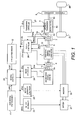
- FIG. 1 is an overall schematic block diagram showing a drive train control system of the hybrid vehicle.
- the drive train of the hybrid vehicle in the illustrated embodiment basically includes a motor/generator 1 as a first power source, an engine 2 as a second power source and left and ride drive wheels (left and right rear wheels) 3L and 3R.
- the power train of the hybrid vehicle shown in Figure 1 has an automatic transmission 4 arranged in tandem on the rearward side of the engine 2 such that rotation (torque) is transmitted from the engine 2 (crankshaft 2a) to an input shaft 4a of the automatic transmission 4 through a shaft 5.
- the motor/generator 1 is connected to the shaft 5.
- the motor/generator 1 is an alternating current (AC) synchronous motor that is arranged between the engine 2 and the transmission 4.
- the motor/generator 1 acts as a motor when it drives the wheels 3L and 3R and acts as a generator when it executes regenerative braking of the wheels 3L and 3R.
- a first clutch 6 is disposed between the motor/generator 1 and the engine 2, i.e., between the shaft 5 and the engine crankshaft 2a.
- the first clutch 6 is configured such that it can connect and disconnect the connection between the engine 2 and the motor/generator 1.
- the first clutch 6 is further configured such that the torque transmission capacity of the first clutch 6 can be varied in a continuous manner or a step-like manner (in stages).
- the first clutch 6 is a multi-plate wet clutch that is configured such that its torque transmission capacity can be varied by controlling the hydraulic oil flow rate and hydraulic oil pressure of the clutch in a continuous manner with a proportional solenoid.
- a second clutch 7 is disposed between the motor/generator 1 and the automatic transmission 4, i.e., between the shaft 5 and the transmission input shaft 4a.
- the second clutch 7 is configured such that it can connect and disconnect the connection between the motor/generator 2 and the automatic transmission 4.
- the second clutch 7 is further configured such that the torque transmission capacity of the second clutch 7 can be varied in a continuous manner or a step-like manner.
- the second clutch 7 is a multi-plate wet clutch that is configured such that its torque transmission capacity can be varied by controlling the hydraulic oil flow rate and hydraulic oil pressure of the clutch in a continuous manner with a proportional solenoid.
- the automatic transmission 4 has at least one torque transmitting path (gear) in which power is transmitted through a one-way clutch 4c.
- that gear is a first gear for forward travel.
- the automatic transmission 4 is configured to select the power transmission path (gear) by connecting and disconnecting the frictional holding members in a selective manner, i.e., by using specific combinations of connected and disconnected holding members.
- the automatic transmission 4 converts the rotation imparted to the input shaft 4a at a gear ratio corresponding to the selected gear and outputs the resulting rotation to an output shaft 4b.
- the output rotation is distributed to the left and right rear wheels 3L and 3R through a final reduction gear 8 that includes a differential.
- the power train of the hybrid vehicle shown in Figure 1 is configured such that when an electric drive (EV) mode is requested, such as when the vehicle is starting into motion from a stopped state or otherwise traveling with a low load and/or at a low speed, the first clutch 6 is released, the second clutch 7 is connected.
- the automatic transmission 4 is put in such a state that it can transmit power from the motor/generator 2 to the left and right rear wheels 3L and 3R. From this state, when the motor/generator 1 is driven, then only the output rotation of the motor/generator 1 reaches the input shaft 4a of the automatic transmission 4, after which the rotation imparted to the input shaft 4a is converted by the automatic transmission 4 at a gear ratio corresponding to the selected gear and outputted from the output shaft 4b.
- EV electric drive
- the rotation of the output shaft 4b is then passes through the final reduction gear 8 (which includes a differential) where torque is distributed to the left and right wheels 3L and 3R. In this way, the vehicle is driven electrically (EV drive) by the motor/generator 1 alone.
- both the first clutch 6 and the second clutch 7 are connected and the automatic transmission 4 is put into such a state that it can transmit power. From this state, the output rotation from both the engine 2 and the motor/generator 1 reaches the input shaft 4a of the automatic transmission 4 and the rotation imparted to the input shaft 4a is then converted by the automatic transmission 4 in accordance with the selected gear and outputted from the output shaft 4b. Then, the rotation from the output shaft 4b of the automatic transmission 4 passes through the final reduction gear 8 where the torque is distributed to the left and right rear wheels 3L and 3R. In this way, the vehicle can be driven in a hybrid fashion (HEV drive) by both the engine 2 and the motor/generator 1.
- HEV hybrid drive
- the engine 2 is basically operated such that the fuel efficiency thereof is optimized.
- the surplus energy is used to operate the motor/generator 1 as a generator and convert the surplus energy into electric energy.
- the fuel efficiency of the engine can be improved.
- Figure 1 illustrates an example in which the second clutch 7 is disposed between the motor/generator 1 and the automatic transmission 4 to connect and disconnect the motor/generator 1 to and from the drive wheels 3L and 3R, it is also acceptable to arrange a second clutch between the automatic transmission 4 and the reduction gear 8, or to configure the automatic transmission 4 such that the frictional holding members used for selecting the gears can be controlled to serve as a second clutch.
- Figure 1 also shows a control system for controlling the engine 2, the motor/generator 1, the first clutch 6, the second clutch 7, and the automatic transmission 4 that make up the power train of the hybrid vehicle.
- the control system is provided with a general controller 20 that controls the overall operating point of the power train.
- the operating point of the power train is defined by the combination of an target engine torque value tTe, a target motor/generator torque value tTm (or a target motor/generator rotational speed value tNm), a target torque transmission capacity value tTc1 (or clutch hydraulic solenoid current Ic1) of the first clutch 6, a target torque transmission capacity value tTc2 (or clutch hydraulic solenoid current Ic2) of the second clutch 7, and a target gear Gm of the automatic transmission 4.
- the general controller 20 receives an input signal from an accelerator position sensor 11 that detects the accelerator position APO and an input signal from a vehicle speed sensor 12 that detects the vehicle speed VSP.
- the motor/generator 1 is driven with electric power from a battery 21 using an inverter 22.
- the motor/generator 1 acts as a generator, the generated electricity is stored in the battery 21.
- the charging of the battery 21 is controlled by a battery controller 23 such that the battery 21 is not overcharged. Therefore, the battery controller 23 detects the state of charge (SOC) of the battery 21 (a value indicating the amount of electric power that can be withdrawn from the battery 21) and sends information related to the state of charge to the general controller 20.
- SOC state of charge
- the general controller 20 Based on the accelerator pedal position APO, the battery state of charge SOC, and the vehicle speed VSP, the general controller 20 selects the operating mode (EV mode or HEV mode) that can achieve the vehicle driving force desired by the driver. Additionally, the controller 20 computes the target engine torque value tTe, the target motor/generator torque value tTm, the first target clutch torque transmission capacity value tTc1 (or clutch hydraulic solenoid current Ic1), the second clutch target torque transmission capacity value tTc2 (or clutch hydraulic solenoid current Ic2), and the target gear Gm of the automatic transmission 4.
- the target engine torque value tTe is sent to an engine controller 24, and the target motor/generator torque value tTm is sent to a motor/generator controller 25.
- the engine controller 24 controls the engine 2 such that the engine torque Te becomes equal to the target engine torque value tTe. Simultaneously, the engine controller 24 feeds a signal from an engine speed sensor 15 to the general controller 20.
- the engine speed sensor 15 detects the engine rotational speed Ne (rotational speed of the input side of the first clutch 6).
- the motor/generator controller 25 controls the motor/generator 1 such that the torque Tm of the motor/generator 1 becomes equal to the target motor/generator torque value tTm.
- the motor/generator controller 25 controls the motor/generator torque Tm with electric power from the battery 21 using the inverter 22.
- the general controller 20 feeds the first target clutch torque transmission capacity value tTc1 (clutch hydraulic solenoid current Ic1) and the second clutch target torque transmission capacity value tTc2 (clutch hydraulic solenoid current Ic2) to the clutch controller 26.
- the clutch controller 26 supplies a clutch hydraulic solenoid current Ic1 corresponding to the first target clutch torque transmission capacity value tTc1 to a hydraulic pressure control solenoid of the first clutch 6.
- the clutch controller 26 controls the connection degree of the first clutch 6 such that the torque transmission capacity Tc1 of the first clutch 6 is equal to the target torque transmission capacity value tTc1.
- the clutch controller 26 supplies a clutch hydraulic solenoid current Ic2 corresponding to the second clutch target torque transmission capacity value tTc2 to a hydraulic pressure control solenoid of the second clutch 7.
- the clutch controller 26 controls the connection degree of the second clutch 7 such that the torque transmission capacity Tc2 of the second clutch 7 is equal to the second clutch target torque transmission capacity value tTc2.
- the general controller 20 sends the computed target gear Gm to a transmission controller 27.
- the transmission controller 27 controls the automatic transmission 4 such that it shifts to the target gear (target gear ratio) Gm.
- the general controller 20 accomplishes the hybrid vehicle control by employing the motor/generator controller 25 to control the rotational speed of the motor/generator 1 to improve the re-acceleration response and reduce the shock associated with engagement of the one-way clutch when the hybrid vehicle changes from a coasting state to an accelerating state (re-acceleration) while the transmission 4 is in a gear in which power is transmitted through the one-way clutch.
- the apparatus includes a second clutch input rotational speed sensor 13, a second clutch output rotational speed sensor 14 and an oil temperature sensor 16.
- the second clutch input rotational speed sensor 13 constitutes a second clutch input rotational speed detecting section serving to detect the rotational speed of the motor/generator 1 by detecting the rotational speed Nc2i of the input side of the second clutch 7.
- the second clutch output rotational speed sensor 14 (constitutes a second clutch output rotational speed detecting section serving to detect the rotational speed of the input shaft 4a of the automatic transmission 4 by detecting the rotational speed Nc2o of the output side of the second clutch 7.
- the oil temperature sensor 16 detects the temperature Temp of the hydraulic oil of the second clutch 7. Signals from these rotational speed sensors 13 and 14 and the oil temperature sensor 16 are fed to the general controller 20 through the clutch controller 26.
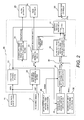
- FIG. 2 illustrates the constituent features of the general control 20 in terms of the functions it performs
- Figure 3 is a flowchart showing a control program executed by the general controller 20 in order to control the rotational speed of the motor/generator 1 as explained below.
- This control program shown in Figure 3 is repeatedly executed with a periodic interrupt (a prescribed time period).
- step S1 the general controller 20 receives data from the other controllers 23 to 27.
- the general controller 20 reads the battery state of charge SOC, the engine speed Ne, the input rotational speed Nc2i of the second clutch 7and the output rotational speed Nc2o of the second clutch 7, the hydraulic oil temperature Temp of the second clutch 7, and the selected gear (gear ratio) Gm of the automatic transmission 4.
- step S2 the general controller 20 reads the accelerator position APO and the vehicle speed VSP based on the signals from the sensors 11 and 12.
- step S3 corresponds to the drive/coast determining section 31 shown in Figure 2.
- step S4 the general controller 20 refers to, for example, the driving force schedule map shown in Figure 5 and determines the target wheel drive torque value tTd based on the vehicle speed VSP and the accelerator pedal APO.
- step S4 corresponds to the target wheel drive torque value computing section 32 shown in Figure 2.
- step S5 the general controller 20 sets a first clutch control mode flag fCL1 based on such vehicle operating conditions as the battery state of charge SOC, the target wheel drive torque value tTd, and the vehicle speed VSP.
- the first clutch control mode flag fCL1 serves to command that the first clutch 6 be connected (engaged) or disconnected (released).
- the setting of the first clutch control mode flag fCL1 can be accomplished in a variety of ways.
- the driving conditions are such that the combustion efficiency of the engine 2 is comparatively poor, e.g., when the vehicle is traveling with a small load and a low speed such as during gradual acceleration from a stopped condition
- the general controller 20 determines that the first clutch 6 should be released and sets the first clutch control mode flag fCL1 to 0 such that the vehicle is driven in EV mode using the motor/generator 1 only and not the engine 2.
- the general controller 20 determines that it is necessary to obtain power from the engine 2, as well.
- the general controller 20 sets the value of the first clutch control mode flag fCL1 to 1 such that the first clutch 6 is connected and the vehicle is driven in HEV mode using both the engine 2 and the motor/generator 1.
- step S6 the general controller 20 sets a second clutch control mode flag CL2MODE based on such vehicle operating conditions as the battery state of charge SOC, the target wheel drive torque value tTd, the first clutch control mode flag fCL1, and the vehicle speed VSP.
- the second clutch control mode flag CL2MODE serves to command that the second clutch 2 be connected (fully engaged), disconnected (released), or connected in a slipping state (partially engaged).
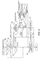
- step S50 of Figure 4 the general controller 20 determines if the vehicle is coasting based on the result of step S3. If the vehicle is coasting, then the general controller 20 determines that the second clutch 7 should be connected and proceeds to step S53, where it sets the value of the second clutch control mode flag CL2 MODE to 1 (connect).
- step S50 determines if the vehicle is not coasting, i.e., if the vehicle is being driven by a power source. If the general controller 20 proceeds to step S51, where it determines if the value of the first clutch control mode flag fCL1 is 0, i.e., if the first clutch 6 should be released. If the value of fCL1 is 0, i.e., if the vehicle should be put into EV mode by releasing the first clutch 6 and stopping the engine 2, then the general controller 20 proceeds to step S52 and determines if the vehicle speed is 0, i.e., if the vehicle is in a stopped state.
- step S53 sets the value of the second clutch control mode flag CL2 MODE to 1 (connect) to connect the second clutch 7 in preparation for the vehicle to start into motion from the stopped state.
- step S51 determines if the first clutch control mode flag fCL1 is not 0, i.e., that the vehicle should be put into HEV mode by connecting the first clutch 6 and starting the engine 2
- the general controller 20 proceeds to step S55 and determines if the vehicle speed VSP is below a set vehicle speed VSPs that is equal to, for example, a minimum vehicle speed at which the engine 2 can be started. In other words, the general controller 20 determines if the vehicle speed is in a region in which the engine 2 cannot be started or a region in which the engine 2 can be started (i.e., in which the vehicle can be driven in HEV mode).
- the purpose of connecting the second clutch 7 in a slipping fashion is to prevent the torque fluctuation that occurs at the motor/generator 1 when the engine 2 is started from being transferred to the drive wheels.
- step S56 If it determines in step S56 that the target drive torque value tTd is smaller than 0, i.e., that a negative drive torque is required, then the general controller 20 proceeds to step S57 and sets the second clutch control mode flag CL2MODE to 0 (release) because the engine 2 cannot be started in a favorable manner from EV mode with the second clutch 7 in a slipping state.
- step S55 If it determines in step S55 that the vehicle speed VSP is equal to or larger than the set vehicle speed VSPs, i.e., that the vehicle speed is in a region in which the engine 2 can be started (i.e., in which the vehicle can be driven in HEV mode), then the general controller 20 proceeds to step S58 and determines if the previous value of the second clutch control mode flag CL2MODE (i.e., the value in the previous control cycle) was 1, i.e., if the second clutch 7 was connected in the previous control cycle.
- the previous value of the second clutch control mode flag CL2MODE i.e., the value in the previous control cycle
- step S58 If it determines in step S58 that the previous value of CL2MODE was 1, i.e., that the second clutch 7 was connected in the previous cycle, then the general controller 20 proceeds to step S53 and holds the second clutch control mode flag CL2MODE at 1 (connected).
- step S58 determines in step S58 that the previous value of CL2MODE was not 1, i.e., that the second clutch 7 was disconnected or connected in a slipping state in the previous cycle. If it determines in step S58 that the previous value of CL2MODE was not 1, i.e., that the second clutch 7 was disconnected or connected in a slipping state in the previous cycle, then the general controller 20 proceeds to step S59 and determines if the engine speed Ne (i.e., the rotational speed of the input side of the first clutch 6) is different from the rotational speed Nc2i of the input side of the second clutch 7 (i.e., the rotational speed of the output side of the first clutch 6) or if the actual slip rotational speed Nc2slip of the second clutch 7 is smaller than a prescribed set value Nc2slipth. In this way, the general controller 20 determines if a condition exists requiring a slip connection of the second clutch 7.
- the engine speed Ne i.e., the rotational speed of the input side of
- step S59 If it determines in step S59 that the second clutch slip connection condition exists, i.e., that the second clutch 7 needs to be connected in a slipping fashion, then the general controller 20 proceeds to step S54 and sets the value of the second clutch control mode flag CL2MODE to 2 (slip).
- step S59 If it determines in step S59 that the second clutch slip connection condition does not exist, i.e., that the second clutch 7 should not be connected in a slipping fashion, then the general controller 20 proceeds to step S53 and sets the value of the second clutch control mode flag CL2MODE to 1 (connect).
- step S7 corresponds to the torque distributing section 33 shown in Figure 2.
- the general controller 20 calculates a base target motor torque value tTmbase and a base target engine torque value tTebase for determining how to distribute the target wheel drive torque value tTd between the motor/generator 1 and the engine 2.
- the base target engine torque value tTebase is sent without modification to the engine controller 24 as the target engine torque value tTe in step S24.
- step S8 the general controller 20 determines if it should execute the slip rotation (connection) control of the second clutch 7. More specifically, the general controller 20 determines that slip rotation (connection) control of the second clutch 7 should be executed (i.e., should be turned ON) if the value of the second clutch control mode flag CL2MODE set in step S6 is 2 (i.e., if the second clutch 7 needs to be connected in a slipping fashion) and the amount of slippage between the input rotational speed Nc2i and the output rotational speed Nc20 of the second clutch 7 is equal to or above a prescribed value. Otherwise, the general controller 20 determines that slip rotation (connection) control of the second clutch 7 should not be executed (i.e., should be turned OFF).
- step S8 If it determines in step S8 that slip rotation (connection) control of the second clutch 7 should be executed, then the general controller 20 proceeds to step S9 and calculates a base target torque transmission capacity value tTc2base of the second clutch 7 corresponding to the vehicle driving operation(s) being executed by the driver and the traveling state of the vehicle.
- the second clutch base target torque transmission capacity value tTc2base can also be calculated as will now be described.
- the second clutch base target torque transmission capacity value tTc2base is then calculated based on the torque transmission capacity coefficient Cc2 and the input side rotational speed Nc2i of the second clutch 7 using the equation (1) below.
- tTc ⁇ 2 ⁇ base Cc ⁇ 2 ⁇ Nc ⁇ 2 ⁇ i ⁇ 2
- the steps S10 to S18 enclosed inside a broken line in Figure 3 constitute a block for calculating a target torque transmission capacity value tTc2slip for slip control of the second clutch 7 and correspond to the second clutch slip control target torque transmission capacity value computing section 34 shown in Figure 2.
- This block of steps appears as shown in Figure 7 when expressed as a block diagram.
- step S10 of Figure 3 the general controller 20 calculates an target output rotational speed value tNc2o of the second clutch 7 based on the target drive torque value tTd calculated in step S4 and calculates a second clutch target input rotational speed value tNc2i required to achieve a second clutch target slip rotational speed value based on the second clutch target slip rotational speed value and the detected value of the second clutch output rotational speed Nc2o (value detected by the sensor 14).
- the target output rotational speed value tNc2o of the second clutch 7 is calculated using the equation (2) below based on the target drive torque value tTd, a moment of inertia Jo of the vehicle, the gear ratio Gm determined by the selected gear of the automatic transmission 4 of the wheel drive train, and the final reduction ratio Gf of the final reduction gear 8 of the wheel drive train.
- tNc ⁇ 2 ⁇ o Gm ⁇ Gf ⁇ 2 / Jo ⁇ 1 / s ⁇ tTd
- step S11 corresponds to the feed forward (phase) compensation computing section 51 shown in Figure 7.
- step S11 a feed forward (phase) compensator Gff(s) applies a phase compensation to the second clutch base target torque transmission capacity value tTc2base calculated in step S9 to obtain a second clutch target torque transmission capacity value Tc2ff for feed forward control.
- the second clutch target torque transmission capacity value tTc2ff for feed forward control is actually calculated using the recurrence formula (3) shown below, which is obtained by discretizing using a Tustin approximation or the like.
- Gc2ref(s) reference model of second clutch;
- Step S12 corresponds to the second clutch output rotational speed reference value computing section 53 shown in Figure 7.
- the general controller 20 passes the second clutch target output rotational speed value tNc2o through the reference model Gc2ref(s) of the second clutch 7 to calculate a second clutch output rotational speed reference value Nc2oref for matching to the reference model.
- the second clutch output rotational speed reference value Nc2oref is actually calculated using the recurrence formula (4) shown below, which is obtained by discretizing using a Tustin approximation or the like.
- Tc2ref reference response time constant for control of second clutch
- Step S13 of Figure 3 corresponds to the second clutch torque transmission capacity revision value computing section 55 shown in Figure 7 and serves to calculate a second clutch torque transmission capacity revision value Tc2fb for adjusting the second clutch output rotational speed error Nc2oerr to 0, i.e., for making the detected second clutch output rotational speed Nc2o match the second clutch output rotational speed reference value Nc2oref.
- the second clutch torque transmission capacity revision value Tc2fb is a feedback control amount.
- the second clutch torque transmission capacity revision value Tc2fb is actually calculated using the recurrence formula (5) shown below, which is obtained by discretizing using a Tustin approximation or the like.
- Tc ⁇ 2 ⁇ fb Kc ⁇ 2 ⁇ p + Kc ⁇ 2 ⁇ i / s ⁇ Nc ⁇ 2 ⁇ oerr
- Kc2p proportional control gain
- step S14 the general controller 20 calculates a torque transmission capacity revision (decrease) value ⁇ Tc2e of the second clutch 7 required to start the engine 2 by connecting the first clutch 6 from a released state.
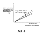
- the general controller 20 finds the second clutch torque transmission capacity revision value ⁇ Tc2e for starting the engine 2 as a function of the motor torque Tengst required to start the engine 2 and the accelerator pedal APO.
- the general controller 20 finds the second clutch torque transmission capacity revision value ⁇ Tc2e for starting the engine 2 by referring to a map like that shown in Figure 8 using the motor torque Tengst required to start the engine 2 and the accelerator pedal APO.
- Step S15 and step S16 of Figure 3 correspond to the second clutch target torque transmission capacity value computing section 56 for second clutch rotation control shown in Figure 7.
- the general controller 20 adds the feed forward control second clutch target torque transmission capacity value tTc2ff and the second clutch torque transmission capacity revision value Tc2fb together and then subtracts the engine start second clutch torque transmission capacity revision value ⁇ Tc2e from the sum to obtain a second clutch target torque transmission capacity value Tc2fbon for slip rotation control of the second clutch 7.
- step S18 the general controller 20 sets the second clutch target torque transmission capacity value Tc2fbon for slip rotation control of the second clutch 7 as the second clutch slip control target torque transmission capacity value tTc2slip.
- step S8 determines in step S8 that slip control of the second clutch 7 should not be executed
- the general controller 20 proceeds to step S16, where it initializes the second clutch target output rotational speed value tNc2o calculated in step S10 to the detected value of the second clutch output rotational speed Nc2o and initializes the integrator used to calculate the second clutch torque transmission capacity revision value Tc2fb calculated in step S13 to 0.
- step S17 in accordance with the determination made in step S8 that slip control of the second clutch 7 should not be executed, the general controller 20 calculates a second clutch target torque transmission capacity value tTc2fboff for normal control of the second clutch 7 in order to connect or disconnect the second clutch 7, hold the second clutch 7 steady in its current connected or disconnected state, or to serve as a target torque transmission capacity value to be used during a period prior to starting slip control of the second clutch 7 from a steady connected or steady disconnected state.
- tTc2fboff for normal control of the second clutch 7 in order to connect or disconnect the second clutch 7, hold the second clutch 7 steady in its current connected or disconnected state, or to serve as a target torque transmission capacity value to be used during a period prior to starting slip control of the second clutch 7 from a steady connected or steady disconnected state.
- the second clutch target torque transmission capacity value tTc2fboff for normal control is set to the maximum value the second clutch 7 can attain. Meanwhile, when the second clutch 7 is to be released or held steady in a released state, the second clutch target torque transmission capacity value tTc2fboff for normal control is gradually decreased from the current torque transmission capacity of the second clutch 7.
- Ksafe represents a second clutch torque transmission capacity safety factor (>1)
- ⁇ Tc2(L/U) represents a rate of increase of torque transmission capacity during connection of second clutch
- the method of calculating the second clutch target torque transmission capacity value tTc2fboff for the situation in which the second clutch is to be disconnected will be presented.
- ⁇ Tc2(SLIP) represents a rate of decrease of torque transmission capacity during shift to slip control of second clutch
- step S18 the general controller 20 sets the target torque transmission capacity value tTc2slip for slip control of the second clutch 7 to the value of the second clutch target torque transmission capacity value tTc2fbon for slip rotation control of the second clutch 7 calculated in step S15 in accordance with the determination that slip control of the second clutch 7 should be executed.
- step S18 the general controller 20 sets the target torque transmission capacity value tTc2slip for slip control of the second clutch 7 to the value of the second clutch target torque transmission capacity value tTc2fboff for normal control of the second clutch 7 calculated in step S17 in accordance with the determination that slip control of the second clutch 7 should not be executed.
- step S18 the general controller 20 sets the second clutch target torque transmission capacity value tTc2slip for slip control of the second clutch 7 determined as described above as the second clutch target torque transmission capacity value tTc2.
- step S20 the general controller 20 determines the target torque transmission capacity value tTc1 of the first clutch 6. More specifically, if the first clutch control mode flag fCL1 was set to 1 in step S5 (so as to connect the first clutch 6) and the actual slip rotational speed Nc2slip of the second clutch 7 is equal to or larger than the second clutch target slip rotational speed value (second clutch target slip rotational speed value for engine starting if engine is to be started), then the general controller 20 sets the first target clutch torque transmission capacity value tTc1 to the value of the maximum attainable torque transmission capacity Tc1 max of the first clutch 6. Meanwhile, if the first clutch control mode flag fCL1 was set to 0 (so as to release the first clutch 6), then the general controller 20 sets the first target clutch torque transmission capacity value tTc1 to 0.
- step S21 the general controller 20 sets the hydraulic solenoid currents Ic2 and Ic1 of the second clutch 7 and the first clutch 6, respectively, that are required in order to achieve the second clutch target torque transmission capacity value tTc2 and first target clutch torque transmission capacity value tTc1 set as described above.
- the general controller 20 uses a schedule map like that shown in Figure 9 to determine the clutch hydraulic pressures required for the second clutch 7 and the first clutch 6 to achieve the second clutch target torque transmission capacity value tTc2 and the first target clutch torque transmission capacity value tTc1, respectively. Then, the general controller 20 uses a map like that shown in Figure 10 to determine the hydraulic solenoid current Ic2 of the second clutch 7 and the hydraulic solenoid current Ic1 of the first clutch 6 necessary to generate the respective clutch hydraulic pressures.
- step S24 the hydraulic solenoid current Ic2 for the second clutch 7 and the hydraulic solenoid current Ic1 for the first clutch 6 will be sent to the clutch controller 26 and the clutch controller 26 will execute connection control of the second clutch 7 and the first clutch 6 such that the torque transmission capacities thereof become equal to the target values tTc2 and tTc1, respectively.
- Step S22 corresponds to a one-way clutch target input/output relative rotational speed value computing section 35, a one-way clutch output rotational speed computing section 36, a one-way clutch target input rotational speed value computing section 37, a one-way clutch input rotational speed computing section 38, a subtractor 39, and a one-way clutch target input/output relative rotational speed control motor torque value computing section 40 shown in Figure 2.
- the general controller 20 sets a one-way clutch target input/output relative rotational speed value t ⁇ Nowc to be used during the period when the automatic transmission 4 is in a gear that transmits power through the one-way clutch.
- tTmslip one-way clutch input/output relative rotational speed control target motor torque value
- the one-way clutch target input/output relative rotational speed value computing section 35 sets the target value t ⁇ Nowc for the input/output relative rotational speed of the one-way clutch (i.e., the rotational speed obtained by subtracting the output side rotational speed from the input side rotational speed) to a small value, e.g., -50 rpm, while the vehicle is coasting. Even more advantageous is to gradually adjust the target value t ⁇ Nowc to 0 at a prescribed rate of change per unit time that will not cause shock to occur when the one-way clutch engages for starting a re-acceleration operation.
- the one-way clutch output rotational speed computing section 36 computes the one-way clutch output rotational speed Nowco based on rotational speed information related to a portion of the drive train on the output side of the one-way clutch, e.g., information from the vehicle speed sensor 12.
- the one-way clutch input rotational speed computing section 38 computes the one-way clutch input rotational speed Nowci based on rotational speed information related to a portion of the drive train on the input side of the one-way clutch, e.g., information from second clutch output rotational speed sensor 14.
- the subtractor 39 subtracts the one-way clutch input rotational speed Nowci from the one-way clutch target input rotational speed value tNowci in order to find the error Nowcerr of the one-way clutch input rotational speed Nowci with respect to the one-way clutch target input rotational speed value tNowci.
- the one-way clutch target input/output relative rotational speed control motor torque value computing section 40 calculates the target motor torque value tTmslip (one-way clutch input/output relative rotational speed control target motor torque value) that the motor/generator 1 needs to output in order to bring the rotational speed error Nowcerr to 0 and make the one-way clutch input rotational speed Nowci equal to the one-way clutch target input rotational speed value tNowci.
- the target motor torque value tTmslip can be calculated, for example, using feedback (PID) control based on the rotational speed error Nowcerr.
- Step S23 of Figure 3 corresponds to the target motor torque value selecting section 41 shown in Figure 2 and is contrived to select the target motor torque value tTm based on the determination result of step S3 (i.e., the drive/coast determining section 31). More specifically, if the hybrid vehicle is in a driven state with the accelerator pedal depressed (APO > 0), then the general controller 20 sets the target motor torque value tTm to the target motor torque value tTmbase for driving force (torque) control calculated in step S7 (i.e., by the torque distributing section 33 of Figure 2).
- the general controller 20 sets the target motor torque value tTm to the target motor torque value tTmslip for one-way clutch input/output relative rotational speed control calculated in step S22 (i.e., by the one-way clutch target input/output relative rotational speed control motor torque value computing section 40 of Figure 2).
- step S23 of Figure 3 target motor torque value selecting section 41 of Figure 2 is contrived to change the target motor torque value tTm from the target motor torque value tTmslip for one-way clutch input/output relative rotational speed control to the base target motor torque value tTmbase for driving force (torque) control.
- step S3 (the drive/coast determining section 31 of Figure 2) is contrived to change the target motor torque value tTm from tTmslip to tTmbase when the target input/output relative rotational speed value t ⁇ Nowc becomes 0, which occurs after re-acceleration operation is performed, i.e., after the accelerator pedal is depressed.
- step S3 (the drive/coast determining section 31 of Figure 2) is contrived to change the target motor torque value tTm from tTmslip to tTmbase when it is determined that a re-acceleration operation has been performed, i.e., that the accelerator pedal has been depressed.
- step S24 the general controller 20 sends the target motor torque value tTm (for the motor/generator 1) determined as just described to the motor/generator controller 25 and the motor/generator controller 25 controls the motor/generator 1 such that the output motor torque becomes equal to the target value tTm.
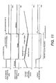
- Figure 11 is an operation time chart for a situation in which the automatic transmission 4 is in a torque transmitting path (gear) in which the power is transmitted from the automatic transmission 4 through the one-way clutch.
- the input rotational speed Nowci of the one-way clutch approaches (increases) even closer to the output rotational speed Nowco such that at the time t3, the input rotational speed Nowci becomes equal to the output rotational speed Nowco.
- the one-way clutch becomes engaged and driving force (torque) is transmitted from the motor/generator 1 to the wheels (i.e., re-acceleration begins).
- the target motor/generator torque value tTm changes from the target value tTmslip for input/output relative rotational speed control of the one-way clutch to the target value tTmbase for driving force (torque) control and normal driving force (torque) control is executed.
- the difference between the input rotational speed Nowci and the output rotational speed Nowco is gradually decreased toward 0 by executing rotational speed control in which the target motor/generator torque value tTm of the motor/generator 1 is set to tTmslip.
- Figure 13 is an operation time chart for a situation in which the transmission is in a torque transmitting path (gear) in which the power is transmitted from the transmission through the one-way clutch.
- the response delay i.e., the amount of time between the time t2 when the re-acceleration operation is started and the time t3 when the input rotational speed Nowci and the output rotational speed Nowco become equal and the one-way clutch engages (vehicle acceleration begins)
- the response delay i.e., the amount of time between the time t2 when the re-acceleration operation is started and the time t3 when the input rotational speed Nowci and the output rotational speed Nowco become equal and the one-way clutch engages (vehicle acceleration begins)
- a large clutch engagement shock occurs immediately after the one-way clutch becomes engaged and acceleration begins at the time t3. This shock is indicated clearly in Figure 13 by the portion of the vehicle acceleration curve occurring immediately after the time t3 (indicated with shading under the curve).
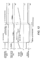
- Figure 12 is an operation time chart for a control apparatus in accordance with another embodiment of the present invention.
- the manner in which the section 41 shown in Figure 2 selects the target motor torque value tTm and the one-way clutch target input/output relative rotational speed value t ⁇ Nowc set by the one-way clutch target input/output relative rotational speed value computing section 35 are different than in the previous embodiment.
- the target motor torque value selecting section 41 selects the target motor torque value tTmslip for one-way clutch input/output relative rotational speed control as the target motor torque value tTm.
- the target motor/generator torque value tTm is controlled to be equal to the value tTmslip.
- the target motor torque value selecting section 41 selects the base target motor torque value tTmbase for driving force (torque) control as the target motor torque value tTm instead of the target motor torque value tTmslip for one-way clutch input/output relative rotational speed control.
- the motor/generator controller 25 shown in Figure 2 receives the command requesting this selection.
- the motor/generator controller 25 changes the target motor torque value tTm from the target motor torque value tTmslip for one-way clutch input/output relative rotational speed control to the base target motor torque value tTmbase for driving force (torque) control
- the motor/generator controller 25 changes the target motor torque value tTm from the target motor torque value tTmslip for one-way clutch input/output relative rotational speed control to the base target motor torque value tTmbase for driving force (torque) control in a gradual manner at a prescribed rate of change per unit time during the period from the time t2 to the time t3 (indicated as a time series change in Figure 12) using a low pass filter.
- the rate of change with which the target motor torque value tTm changes from tTmslip to tTmbase is set to the largest possible value at which sudden changes in motor torque will not cause significant shock (i.e., shock large enough to be a problem) to occur.
- the input rotational speed Nowci of the one-way clutch is already equal to the output rotational speed Nowco of the one-way clutch at the time t2 when the re-acceleration operation is performed and engagement shock of the one-way clutch resulting from the re-acceleration operation can be eliminated.
- the target motor torque value tTm is changed gradually from tTmslip to tTmbase at a prescribed rate of change per unit time during the period from the time t2 (when the re-acceleration operation is performed) to the time t3, the change in the motor torque does not cause any significant shock to occur and the re-acceleration response delay between the time t2 and the time t3 is not large enough to be a problem, as is clear from the curve indicating the change in the vehicle acceleration during the period between the time t2 and the time t3 in Figure 12.
- the method of using a low pass filter to accomplish changing the target motor torque value tTm from the target motor torque value tTmslip for one-way clutch input/output relative rotational speed control to the base target motor torque value tTmbase for driving force (torque) control in a gradual manner at a prescribed rate of change per unit time can also be employed in the previous embodiment (which was explained previously with reference to Figure 11).
- the input rotational speed Nowci of the one-way clutch approaches (increases) even closer to the output rotational speed Nowco such that at the time t3, the input rotational speed Nowci becomes equal to the output rotational speed Nowco.
- the target motor/generator torque value tTm changes from the target value tTmslip for input/output relative rotational speed control of the one-way clutch to the target value tTmbase for driving force (torque) control and the apparatus shifts from one-way clutch input/output relative rotational speed control to normal driving force (torque) control.
- a low pass filter can be used to prevent the occurrence of a large engagement shock at the time t3 when the input rotational speed Nowci of the one-way clutch becomes equal to the output rotation speed Nowco of the one-way clutch such that the one-clutch becomes engaged (re-acceleration starts).
- a low pass filter can be used to change the target motor/generator torque value tTm from the target value tTmslip for one-way clutch input/output relative rotational speed control to the target value tTmbase for driving force (torque) control in a gradual manner at a prescribed rate of change per unit time such that the change in the motor torque does not cause engagement shock of the one-way clutch to occur.
Landscapes
- Engineering & Computer Science (AREA)
- Chemical & Material Sciences (AREA)
- Combustion & Propulsion (AREA)
- Transportation (AREA)
- Mechanical Engineering (AREA)
- Automation & Control Theory (AREA)
- Hybrid Electric Vehicles (AREA)
- Electric Propulsion And Braking For Vehicles (AREA)
- Control Of Transmission Device (AREA)
Abstract
Description
- The present invention generally relates to a hybrid vehicle control apparatus and particularly, but not exclusively, to an apparatus for selectively controlling power from a motor/generator as well as power from an engine to selectively obtain an electric drive (EV) mode in which the vehicle is driven solely with power from the motor/generator and a hybrid drive (HEV) mode in which the vehicle is driven with power from both the engine and the motor/generator. Aspects of the invention relate to an apparatus, to a method and to a vehicle.
- Various hybrid drive apparatus configurations have been proposed for use in hybrid vehicles. One known example of such a configuration is disclosed in
Japanese Laid-Open Patent Publication No. 11-082260 Japanese Laid-Open Patent Publication No. 11-082260 - In a hybrid vehicle equipped with such a hybrid drive apparatus, an electric drive (EV) mode in which the vehicle is driven solely with power from the motor/generator is obtained when the first clutch is released and the second clutch is connected. Meanwhile, a hybrid drive (HEV) mode in which the vehicle can be driven with power from both the engine and the motor/generator is obtained when both the first clutch and the second clutch are connected.
- It has been discovered that in the automatic transmission used in the above mentioned hybrid vehicle, the automatic transmission is often provided with a gear in which power from the engine and/or the motor/generator is transmitted through a one-way clutch such that physical shock resulting from gear shifting can be eliminated with a simple shift control.
- When the transmission is in such gear and the hybrid vehicle is accelerating by depressing an accelerator pedal, the power is transmitted through the one-way clutch which is engaged. Conversely, when the accelerator pedal is released and the vehicle is coasting due to inertia, the input side of the one-way clutch rotates more slowly than the output side and the one-way clutch is released such that the input side is rotating freely without being driven by the output side.
- Additionally, when a hybrid vehicle is coasting, the power sources, i.e., the engine and the motor/generator, are typically stopped to improve the fuel efficiency of the vehicle. Consequently, an undesirably large response delay can occur between when the driver starts to accelerate with the one-way clutch being engaged again.
- It is an aim of the invention to address this issue and to improve upon known technology. The applicants have recognized that in the kind of hybrid vehicle described above, it is possible to control a rotational speed of the input side of the one-way clutch when the vehicle is coasting before an acceleration operation is performed by controlling the rotational speed of the motor/generator in such a fashion that power is not transmitted from the motor/generator to the wheels. Embodiments of the invention may provide a hybrid vehicle control apparatus that can resolve the aforementioned problems of a long response delay and one-way clutch engagement shock by controlling the rotational speed of the motor/generator while the vehicle is coasting prior to re-acceleration. Other aims and advantages of the invention will become apparent from the following description, claims and drawings.
- Aspects of the invention therefore provide an apparatus, a method and a vehicle as claimed in the appended claims.
- According to another aspect of the invention there is provided a hybrid vehicle control apparatus comprising an engine, a transmission including at least one torque transmitting path that transmits power through a one-way clutch, a motor/generator arranged between the engine and the transmission, a first clutch with a variable torque transmission capacity being disposed between the engine and the motor/generator, a second clutch with a variable torque transmission capacity being disposed in a power train that spans from the motor/generator to a drive wheel via the transmission and a controller configured to disengage the first clutch and engage the second clutch to select an electric drive mode in which the engine is stopped and the drive wheel is driven solely with power from the motor/generator, and to engage both the first and second clutches to select a hybrid drive mode in which the drive wheel is driven with power from both the engine and the motor/generator, the controller being further configured to execute a rotational speed control of the motor/generator while in a coasting state with the transmission in the torque transmitting path that transmits power through the one-way clutch such that the rotational speed control increases a rotational speed of an input side of the one-way clutch to a value closer to a rotational speed of an output side of the one-way clutch with a difference between the rotational speeds of the input and output sides of the one-way clutch becoming equal to a target value.
- In an embodiment, the controller is configured to execute a subsequent rotational speed control of the motor/generator that is separate from a drive request imposed on the motor/generator from a re-acceleration operation, when the acceleration operation is performed from the coasting state, such that the subsequent rotational speed control increases the rotational speed of the input side of the one-way clutch closer to the rotational speed of the output side of the one-way clutch with the difference between the rotational speeds of the input and output sides of the one-way clutch becoming smaller than the target value.
- In an embodiment, the controller is configured to execute the subsequent rotational speed control of the motor/generator executed when the re-acceleration operation is performed such that the rotational speed of the input side of the one-way clutch is increased until the difference between the rotational speeds of the input and output sides of the one-way clutch becomes zero.
- In an embodiment, the controller is configured to switch from the subsequent rotational speed control of the motor/generator to a torque control of the motor/generator after the vehicle has undergone acceleration from the coasting state and the rotational speed control of the motor/generator has made the rotational speeds of the input and output sides of the one-way clutch equal.
- In an embodiment, the controller is configured to control the switch from the subsequent rotational speed control to the torque control of the motor/generator such that a target motor torque value of the motor/generator is changed gradually at a prescribed rate of change per unit time from a target value for the rotational speed control to a target value for the torque control.
- In an embodiment, the controller is configured to set the target value regarding the difference between the rotational speeds of the input and output sides of the one-way clutch to zero such that the rotational speed control of the motor/generator executed during the coasting state causes the rotational speeds of the input and output sides of the one-way clutch to be equal.
- In an embodiment, the controller is configured to switch from the rotational speed control of the motor/generator to a torque control of the motor/generator when an acceleration operation is performed from the coasting state.
- The controller may be configured to control the switch from the rotational speed control to the torque control of the motor/generator such that a target motor torque value of the motor/generator is changed gradually at a prescribed rate of change per unit time from a target value for the rotational speed control to a target value for the torque control.
- According to a further aspect of the invention there is provided a hybrid vehicle control apparatus comprising first drive force generating means for generating a first drive force, power transmission means for establishing a torque transmitting path that transmits power through a one-way clutch, second drive force generating means for generating a second drive force between the engine and the transmission, first variable torque transmission capacity clutch means for selectively engaging and disengaging the first and second drive force generating means, second variable torque transmission capacity clutch means for selectively controlling torque in a power train that spans from the second drive force generating means to a drive wheel via the power transmission means and control means for disengaging the first variable torque transmission capacity clutch means and engaging the second variable torque transmission capacity clutch means to select an electric drive mode in which the first drive force generating means is stopped and the drive wheel is driven solely with power from the second drive force generating means, and for engaging both the first and second variable torque transmission capacity clutch means to select a hybrid drive mode in which the drive wheel is driven with power from both the first and second drive force generating means, the control means further performing execution of a rotational speed control of the second drive force generating means while in a coasting state with the power transmission means in the torque transmitting path that transmits power through the one-way clutch such that the rotational speed control increases a rotational speed of an input side of the one-way clutch to a value closer to a rotational speed of an output side of the one-way clutch with a difference between the rotational speeds of the input and output sides of the one-way clutch becoming equal to a target value.
- According to a still further aspect of the invention there is provided a hybrid vehicle control method comprising selectively generating a first drive force with an engine, selectively controlling a transmission to establish a torque transmitting path that transmits power through a one-way clutch, selectively generating a second drive force with a motor/generator arranged between the engine and the transmission and selectively controlling a first clutch with a variable torque transmission capacity being disposed between the engine and the motor/generator and a second clutch with a variable torque transmission capacity being disposed in a power train that spans from the motor/generator to a drive wheel via the transmission such that an electric drive mode is selected in which the engine is stopped and the drive wheel is driven solely with power from the motor/generator by disengaging the first clutch and engaging the second clutch, and a hybrid drive mode is selected in which the drive wheel is driven with power from both the engine and the motor/generator by engaging both the first and second clutches and performing a rotational speed control of the motor/generator while in a coasting state with the transmission in the gear that transmits power through the one-way clutch such that the rotational speed control increases a rotational speed of an input side of the one-way clutch to a value closer to a rotational speed of an output side of the one-way clutch with a difference between the rotational speeds of the input and output sides of the one-way clutch becoming equal to a target value.
- For example, a hybrid vehicle control apparatus may comprise an engine, a transmission, a motor/generator, a first clutch, a second clutch and a controller in accordance with one aspect of the present invention. The transmission may include at least one torque transmitting path that transmits power through a one-way clutch. The motor/generator may be arranged between the engine and the transmission. The first clutch has a variable torque transmission capacity and is disposed between the engine and the motor/generator. The second clutch has a variable torque transmission capacity and is disposed in a power train that spans from the motor/generator to a drive wheel via the transmission. The controller is configured to disengage the first clutch and engage the second clutch to select an electric drive mode in which the engine is stopped and the drive wheel is driven solely with power from the motor/generator. The controller is configured to engage both the first and second clutches to select a hybrid drive mode in which the drive wheel is driven with power from both the engine and the motor/generator. The controller is further configured to execute a rotational speed control of the motor/generator while in a coasting state with the transmission in the torque transmitting path that transmits power through the one-way clutch such that the rotational speed control increases a rotational speed of an input side of the one-way clutch to a value closer to a rotational speed of an output side of the one-way clutch with a difference between the rotational speeds of the input and output sides of the one-way clutch becoming equal to a target value.
- Within the scope of this application it is envisaged that the various aspects, embodiments, examples, features and alternatives set out in the preceding paragraphs, in the claims and/or in the following description may be taken individually or in any combination thereof.
- The present invention will now be described, by way of example only, with reference to the accompanying drawings in which:
- Figure 1 overall schematic block diagram of a power train of a hybrid vehicle equipped with a hybrid vehicle control apparatus in accordance with an embodiment of the present invention;
- Figure 2 is a control block diagram illustrating the computer programming executed by a general controller of the hybrid vehicle control apparatus in accordance with the illustrated embodiment of Figure 1;
- Figure 3 is a flowchart showing a control program executed by the general controller shown in Figure 1;
- Figure 4 is a flowchart showing a control program executed by the general controller for determining the second clutch control mode during the control program of Figure 3;
- Figure 5 is a driving force schedule map that is used to find a target wheel drive torque value;
- Figure 6 is a torque transmission capacity schedule map that is used to find a torque transmission capacity of the second clutch shown in Figure 1;
- Figure 7 is control block diagram illustrating the computer programming of the second clutch connection control portion of the control program shown in Figure 3;
- Figure 8 is a second clutch torque transmission capacity characteristic map for determining a second clutch torque transmission capacity revision value for starting the engine;
- Figure 9 is a clutch hydraulic pressure schedule map that is used to find a clutch hydraulic pressure corresponding to a target clutch torque transmission capacity value;
- Figure 10 is a hydraulic solenoid current schedule map used to find a hydraulic solenoid current required to generate the clutch hydraulic pressure found using Figure 9;
- Figure 11 is a time chart illustrating the operation of the hybrid vehicle control apparatus shown in Figures 1 to 3;
- Figure 12 is a time chart, similar to Figure 11, illustrating the operation of a hybrid vehicle control apparatus in accordance with another embodiment of the present invention; and
- Figure 13 is a time chart illustrating the operation of a hybrid vehicle control apparatus in accordance with a comparative example.
- Selected embodiments of the present invention will now be explained with reference to the drawings. It will be apparent to those skilled in the art from this disclosure that the following descriptions of the embodiments of the present invention are provided for illustration only and not for the purpose of limiting the invention as defined by the appended claims and their equivalents.
- Referring initially to Figure 1, a wheel drive train (power train) of a hybrid vehicle having a hybrid vehicle control apparatus in accordance with an illustrated embodiment of the present invention is explained. In this example, the hybrid vehicle is arranged as a rear wheel drive hybrid vehicle. Figure 1 is an overall schematic block diagram showing a drive train control system of the hybrid vehicle. As shown in Figure 1, the drive train of the hybrid vehicle in the illustrated embodiment basically includes a motor/
generator 1 as a first power source, anengine 2 as a second power source and left and ride drive wheels (left and right rear wheels) 3L and 3R. - Similarly to a typical rear wheel drive vehicle, the power train of the hybrid vehicle shown in Figure 1 has an
automatic transmission 4 arranged in tandem on the rearward side of theengine 2 such that rotation (torque) is transmitted from the engine 2 (crankshaft 2a) to aninput shaft 4a of theautomatic transmission 4 through ashaft 5. The motor/generator 1 is connected to theshaft 5. - The motor/
generator 1 is an alternating current (AC) synchronous motor that is arranged between theengine 2 and thetransmission 4. The motor/generator 1 acts as a motor when it drives thewheels wheels - A
first clutch 6 is disposed between the motor/generator 1 and theengine 2, i.e., between theshaft 5 and theengine crankshaft 2a. Thefirst clutch 6 is configured such that it can connect and disconnect the connection between theengine 2 and the motor/generator 1. Thefirst clutch 6 is further configured such that the torque transmission capacity of thefirst clutch 6 can be varied in a continuous manner or a step-like manner (in stages). For example, thefirst clutch 6 is a multi-plate wet clutch that is configured such that its torque transmission capacity can be varied by controlling the hydraulic oil flow rate and hydraulic oil pressure of the clutch in a continuous manner with a proportional solenoid. - A
second clutch 7 is disposed between the motor/generator 1 and theautomatic transmission 4, i.e., between theshaft 5 and thetransmission input shaft 4a. Thesecond clutch 7 is configured such that it can connect and disconnect the connection between the motor/generator 2 and theautomatic transmission 4. Similarly to thefirst clutch 6, thesecond clutch 7 is further configured such that the torque transmission capacity of thesecond clutch 7 can be varied in a continuous manner or a step-like manner. For example, thesecond clutch 7 is a multi-plate wet clutch that is configured such that its torque transmission capacity can be varied by controlling the hydraulic oil flow rate and hydraulic oil pressure of the clutch in a continuous manner with a proportional solenoid. - The
automatic transmission 4 has at least one torque transmitting path (gear) in which power is transmitted through a one-way clutch 4c. In this embodiment, that gear is a first gear for forward travel. Theautomatic transmission 4 is configured to select the power transmission path (gear) by connecting and disconnecting the frictional holding members in a selective manner, i.e., by using specific combinations of connected and disconnected holding members. Thus, theautomatic transmission 4 converts the rotation imparted to theinput shaft 4a at a gear ratio corresponding to the selected gear and outputs the resulting rotation to anoutput shaft 4b. The output rotation is distributed to the left and rightrear wheels final reduction gear 8 that includes a differential. - The power train of the hybrid vehicle shown in Figure 1 is configured such that when an electric drive (EV) mode is requested, such as when the vehicle is starting into motion from a stopped state or otherwise traveling with a low load and/or at a low speed, the
first clutch 6 is released, thesecond clutch 7 is connected. Thus, theautomatic transmission 4 is put in such a state that it can transmit power from the motor/generator 2 to the left and rightrear wheels generator 1 is driven, then only the output rotation of the motor/generator 1 reaches theinput shaft 4a of theautomatic transmission 4, after which the rotation imparted to theinput shaft 4a is converted by theautomatic transmission 4 at a gear ratio corresponding to the selected gear and outputted from theoutput shaft 4b. The rotation of theoutput shaft 4b is then passes through the final reduction gear 8 (which includes a differential) where torque is distributed to the left andright wheels generator 1 alone. - When there is a request for the hybrid drive (HEV) mode, such as when the traveling speed is high, the load is large, or the amount of electric power that can be obtained from the battery is low, both the
first clutch 6 and thesecond clutch 7 are connected and theautomatic transmission 4 is put into such a state that it can transmit power. From this state, the output rotation from both theengine 2 and the motor/generator 1 reaches theinput shaft 4a of theautomatic transmission 4 and the rotation imparted to theinput shaft 4a is then converted by theautomatic transmission 4 in accordance with the selected gear and outputted from theoutput shaft 4b. Then, the rotation from theoutput shaft 4b of theautomatic transmission 4 passes through thefinal reduction gear 8 where the torque is distributed to the left and rightrear wheels engine 2 and the motor/generator 1. - During HEV mode, the
engine 2 is basically operated such that the fuel efficiency thereof is optimized. When operating theengine 2 such that its fuel efficiency is optimized causes a surplus of energy to occur, the surplus energy is used to operate the motor/generator 1 as a generator and convert the surplus energy into electric energy. By storing the generated electric energy and using it to drive the motor/generator 1 as a motor, the fuel efficiency of the engine can be improved. - Although Figure 1 illustrates an example in which the
second clutch 7 is disposed between the motor/generator 1 and theautomatic transmission 4 to connect and disconnect the motor/generator 1 to and from thedrive wheels automatic transmission 4 and thereduction gear 8, or to configure theautomatic transmission 4 such that the frictional holding members used for selecting the gears can be controlled to serve as a second clutch. - Figure 1 also shows a control system for controlling the
engine 2, the motor/generator 1, thefirst clutch 6, thesecond clutch 7, and theautomatic transmission 4 that make up the power train of the hybrid vehicle. As shown in Figure 1, the control system is provided with ageneral controller 20 that controls the overall operating point of the power train. The operating point of the power train is defined by the combination of an target engine torque value tTe, a target motor/generator torque value tTm (or a target motor/generator rotational speed value tNm), a target torque transmission capacity value tTc1 (or clutch hydraulic solenoid current Ic1) of thefirst clutch 6, a target torque transmission capacity value tTc2 (or clutch hydraulic solenoid current Ic2) of thesecond clutch 7, and a target gear Gm of theautomatic transmission 4. In order to determine the operating point of the power train, thegeneral controller 20 receives an input signal from anaccelerator position sensor 11 that detects the accelerator position APO and an input signal from avehicle speed sensor 12 that detects the vehicle speed VSP. - The motor/
generator 1 is driven with electric power from abattery 21 using aninverter 22. When the motor/generator 1 acts as a generator, the generated electricity is stored in thebattery 21. When electricity is stored in thebattery 21, the charging of thebattery 21 is controlled by abattery controller 23 such that thebattery 21 is not overcharged. Therefore, thebattery controller 23 detects the state of charge (SOC) of the battery 21 (a value indicating the amount of electric power that can be withdrawn from the battery 21) and sends information related to the state of charge to thegeneral controller 20. - Based on the accelerator pedal position APO, the battery state of charge SOC, and the vehicle speed VSP, the
general controller 20 selects the operating mode (EV mode or HEV mode) that can achieve the vehicle driving force desired by the driver. Additionally, thecontroller 20 computes the target engine torque value tTe, the target motor/generator torque value tTm, the first target clutch torque transmission capacity value tTc1 (or clutch hydraulic solenoid current Ic1), the second clutch target torque transmission capacity value tTc2 (or clutch hydraulic solenoid current Ic2), and the target gear Gm of theautomatic transmission 4. The target engine torque value tTe is sent to anengine controller 24, and the target motor/generator torque value tTm is sent to a motor/generator controller 25. - The
engine controller 24 controls theengine 2 such that the engine torque Te becomes equal to the target engine torque value tTe. Simultaneously, theengine controller 24 feeds a signal from anengine speed sensor 15 to thegeneral controller 20. Theengine speed sensor 15 detects the engine rotational speed Ne (rotational speed of the input side of the first clutch 6). The motor/generator controller 25 controls the motor/generator 1 such that the torque Tm of the motor/generator 1 becomes equal to the target motor/generator torque value tTm. The motor/generator controller 25 controls the motor/generator torque Tm with electric power from thebattery 21 using theinverter 22. - The
general controller 20 feeds the first target clutch torque transmission capacity value tTc1 (clutch hydraulic solenoid current Ic1) and the second clutch target torque transmission capacity value tTc2 (clutch hydraulic solenoid current Ic2) to theclutch controller 26. Theclutch controller 26 supplies a clutch hydraulic solenoid current Ic1 corresponding to the first target clutch torque transmission capacity value tTc1 to a hydraulic pressure control solenoid of thefirst clutch 6. Thus, theclutch controller 26 controls the connection degree of thefirst clutch 6 such that the torque transmission capacity Tc1 of thefirst clutch 6 is equal to the target torque transmission capacity value tTc1. - Meanwhile, the
clutch controller 26 supplies a clutch hydraulic solenoid current Ic2 corresponding to the second clutch target torque transmission capacity value tTc2 to a hydraulic pressure control solenoid of thesecond clutch 7. Thus, theclutch controller 26 controls the connection degree of thesecond clutch 7 such that the torque transmission capacity Tc2 of thesecond clutch 7 is equal to the second clutch target torque transmission capacity value tTc2. - The
general controller 20 sends the computed target gear Gm to atransmission controller 27. Thetransmission controller 27 controls theautomatic transmission 4 such that it shifts to the target gear (target gear ratio) Gm. - In this embodiment, the
general controller 20 accomplishes the hybrid vehicle control by employing the motor/generator controller 25 to control the rotational speed of the motor/generator 1 to improve the re-acceleration response and reduce the shock associated with engagement of the one-way clutch when the hybrid vehicle changes from a coasting state to an accelerating state (re-acceleration) while thetransmission 4 is in a gear in which power is transmitted through the one-way clutch. In this embodiment, the apparatus includes a second clutch inputrotational speed sensor 13, a second clutch outputrotational speed sensor 14 and anoil temperature sensor 16. The second clutch inputrotational speed sensor 13 constitutes a second clutch input rotational speed detecting section serving to detect the rotational speed of the motor/generator 1 by detecting the rotational speed Nc2i of the input side of thesecond clutch 7. The second clutch output rotational speed sensor 14 (constitutes a second clutch output rotational speed detecting section serving to detect the rotational speed of theinput shaft 4a of theautomatic transmission 4 by detecting the rotational speed Nc2o of the output side of thesecond clutch 7. Theoil temperature sensor 16 detects the temperature Temp of the hydraulic oil of thesecond clutch 7. Signals from theserotational speed sensors oil temperature sensor 16 are fed to thegeneral controller 20 through theclutch controller 26. - The block diagram of Figure 2 illustrates the constituent features of the
general control 20 in terms of the functions it performs, while Figure 3 is a flowchart showing a control program executed by thegeneral controller 20 in order to control the rotational speed of the motor/generator 1 as explained below. This control program shown in Figure 3 is repeatedly executed with a periodic interrupt (a prescribed time period). - In step S1, the
general controller 20 receives data from theother controllers 23 to 27. Thus, thegeneral controller 20 reads the battery state of charge SOC, the engine speed Ne, the input rotational speed Nc2i of the second clutch 7and the output rotational speed Nc2o of thesecond clutch 7, the hydraulic oil temperature Temp of thesecond clutch 7, and the selected gear (gear ratio) Gm of theautomatic transmission 4. - In step S2, the
general controller 20 reads the accelerator position APO and the vehicle speed VSP based on the signals from thesensors - In step S3, based on the accelerator position APO, the
general controller 20 determines if the hybrid vehicle is in a drive state in which the accelerator pedal is depressed (i.e., APO > 0) or if the hybrid vehicle is in a coasting state in which the accelerator pedal is released (i.e., APO = 0). Thus, step S3 corresponds to the drive/coast determining section 31 shown in Figure 2. - In step S4, the
general controller 20 refers to, for example, the driving force schedule map shown in Figure 5 and determines the target wheel drive torque value tTd based on the vehicle speed VSP and the accelerator pedal APO. Thus, step S4 corresponds to the target wheel drive torquevalue computing section 32 shown in Figure 2. - In step S5, the
general controller 20 sets a first clutch control mode flag fCL1 based on such vehicle operating conditions as the battery state of charge SOC, the target wheel drive torque value tTd, and the vehicle speed VSP. The first clutch control mode flag fCL1 serves to command that thefirst clutch 6 be connected (engaged) or disconnected (released). - The setting of the first clutch control mode flag fCL1 can be accomplished in a variety of ways. In brief, when the driving conditions are such that the combustion efficiency of the
engine 2 is comparatively poor, e.g., when the vehicle is traveling with a small load and a low speed such as during gradual acceleration from a stopped condition, thegeneral controller 20 determines that thefirst clutch 6 should be released and sets the first clutch control mode flag fCL1 to 0 such that the vehicle is driven in EV mode using the motor/generator 1 only and not theengine 2. Meanwhile, when the battery state of charge SOC is below a set value and it is difficult to drive the vehicle in EV mode or when the vehicle is accelerating rapidly or traveling at a high speed and a sufficient driving force cannot be obtained with power from the motor/generator 1 alone, then thegeneral controller 20 determines that it is necessary to obtain power from theengine 2, as well. Thus, thegeneral controller 20 sets the value of the first clutch control mode flag fCL1 to 1 such that thefirst clutch 6 is connected and the vehicle is driven in HEV mode using both theengine 2 and the motor/generator 1. - In step S6, the
general controller 20 sets a second clutch control mode flag CL2MODE based on such vehicle operating conditions as the battery state of charge SOC, the target wheel drive torque value tTd, the first clutch control mode flag fCL1, and the vehicle speed VSP. The second clutch control mode flag CL2MODE serves to command that thesecond clutch 2 be connected (fully engaged), disconnected (released), or connected in a slipping state (partially engaged). - The value of the second clutch control mode flag CL2MODE is set by executing the control program shown in Figure 4. In step S50 of Figure 4, the
general controller 20 determines if the vehicle is coasting based on the result of step S3. If the vehicle is coasting, then thegeneral controller 20 determines that thesecond clutch 7 should be connected and proceeds to step S53, where it sets the value of the second clutch control mode flag CL2 MODE to 1 (connect). - Meanwhile, if it determines in step S50 that the vehicle is not coasting, i.e., if the vehicle is being driven by a power source, then the
general controller 20 proceeds to step S51, where it determines if the value of the first clutch control mode flag fCL1 is 0, i.e., if thefirst clutch 6 should be released. If the value of fCL1 is 0, i.e., if the vehicle should be put into EV mode by releasing thefirst clutch 6 and stopping theengine 2, then thegeneral controller 20 proceeds to step S52 and determines if the vehicle speed is 0, i.e., if the vehicle is in a stopped state. - If the vehicle is in a stopped state, then the
general controller 20 proceeds to step S53, where it sets the value of the second clutch control mode flag CL2 MODE to 1 (connect) to connect thesecond clutch 7 in preparation for the vehicle to start into motion from the stopped state. - If the vehicle speed VSP is determined not to be 0 in step S52, i.e., if the vehicle is traveling (in EV mode), then the
general controller 20 proceeds to step S54 and sets the second clutch control mode flag CL2MODE = 2 (slip) to connect thesecond clutch 7 in a slipping fashion in preparation for theengine 2 to be started. - If it determines in step S51 that the first clutch control mode flag fCL1 is not 0, i.e., that the vehicle should be put into HEV mode by connecting the
first clutch 6 and starting theengine 2, thegeneral controller 20 proceeds to step S55 and determines if the vehicle speed VSP is below a set vehicle speed VSPs that is equal to, for example, a minimum vehicle speed at which theengine 2 can be started. In other words, thegeneral controller 20 determines if the vehicle speed is in a region in which theengine 2 cannot be started or a region in which theengine 2 can be started (i.e., in which the vehicle can be driven in HEV mode). - If the vehicle speed VSP is below the set vehicle speed VSPs (i.e., in a region where the
engine 2 cannot be started, which is an EV drive region), then thegeneral controller 20 proceeds to step S56 and determines the sign of the target drive torque value tTd. If the value tTd is larger than 0, i.e., if a positive drive torque is required, then thegeneral controller 20 proceeds to step S54 and sets the second clutch control mode flag CL2MODE = 2 (slip) to connect thesecond clutch 7 in a slipping fashion in preparation for theengine 2 to be started. The purpose of connecting thesecond clutch 7 in a slipping fashion is to prevent the torque fluctuation that occurs at the motor/generator 1 when theengine 2 is started from being transferred to the drive wheels. - If it determines in step S56 that the target drive torque value tTd is smaller than 0, i.e., that a negative drive torque is required, then the
general controller 20 proceeds to step S57 and sets the second clutch control mode flag CL2MODE to 0 (release) because theengine 2 cannot be started in a favorable manner from EV mode with thesecond clutch 7 in a slipping state. - If it determines in step S55 that the vehicle speed VSP is equal to or larger than the set vehicle speed VSPs, i.e., that the vehicle speed is in a region in which the
engine 2 can be started (i.e., in which the vehicle can be driven in HEV mode), then thegeneral controller 20 proceeds to step S58 and determines if the previous value of the second clutch control mode flag CL2MODE (i.e., the value in the previous control cycle) was 1, i.e., if thesecond clutch 7 was connected in the previous control cycle. - If it determines in step S58 that the previous value of CL2MODE was 1, i.e., that the
second clutch 7 was connected in the previous cycle, then thegeneral controller 20 proceeds to step S53 and holds the second clutch control mode flag CL2MODE at 1 (connected). - If it determines in step S58 that the previous value of CL2MODE was not 1, i.e., that the
second clutch 7 was disconnected or connected in a slipping state in the previous cycle, then thegeneral controller 20 proceeds to step S59 and determines if the engine speed Ne (i.e., the rotational speed of the input side of the first clutch 6) is different from the rotational speed Nc2i of the input side of the second clutch 7 (i.e., the rotational speed of the output side of the first clutch 6) or if the actual slip rotational speed Nc2slip of thesecond clutch 7 is smaller than a prescribed set value Nc2slipth. In this way, thegeneral controller 20 determines if a condition exists requiring a slip connection of thesecond clutch 7. - If it determines in step S59 that the second clutch slip connection condition exists, i.e., that the
second clutch 7 needs to be connected in a slipping fashion, then thegeneral controller 20 proceeds to step S54 and sets the value of the second clutch control mode flag CL2MODE to 2 (slip). - If it determines in step S59 that the second clutch slip connection condition does not exist, i.e., that the
second clutch 7 should not be connected in a slipping fashion, then thegeneral controller 20 proceeds to step S53 and sets the value of the second clutch control mode flag CL2MODE to 1 (connect). - After completing step S6 of Figure 3, i.e., after setting the second clutch control mode flag CL2MODE by executing the control program shown in Figure 4, the
general controller 20 proceeds to step S7 of Figure 3. Step S7 corresponds to thetorque distributing section 33 shown in Figure 2. In step S7, thegeneral controller 20 calculates a base target motor torque value tTmbase and a base target engine torque value tTebase for determining how to distribute the target wheel drive torque value tTd between the motor/generator 1 and theengine 2. The base target engine torque value tTebase is sent without modification to theengine controller 24 as the target engine torque value tTe in step S24. - There are no particular limitations on the method of distributing the target wheel drive torque value tTd; a detailed explanation thereof is omitted here because it is not relevant to the present invention.
- In step S8, the
general controller 20 determines if it should execute the slip rotation (connection) control of thesecond clutch 7. More specifically, thegeneral controller 20 determines that slip rotation (connection) control of thesecond clutch 7 should be executed (i.e., should be turned ON) if the value of the second clutch control mode flag CL2MODE set in step S6 is 2 (i.e., if thesecond clutch 7 needs to be connected in a slipping fashion) and the amount of slippage between the input rotational speed Nc2i and the output rotational speed Nc20 of thesecond clutch 7 is equal to or above a prescribed value. Otherwise, thegeneral controller 20 determines that slip rotation (connection) control of thesecond clutch 7 should not be executed (i.e., should be turned OFF). - If it determines in step S8 that slip rotation (connection) control of the
second clutch 7 should be executed, then thegeneral controller 20 proceeds to step S9 and calculates a base target torque transmission capacity value tTc2base of thesecond clutch 7 corresponding to the vehicle driving operation(s) being executed by the driver and the traveling state of the vehicle. - Although it is acceptable to use the target wheel drive torque value tTd calculated in step S4 based on the accelerator position APO and the vehicle speed VSP as the second clutch base target torque transmission capacity value tTc2base, the second clutch base target torque transmission capacity value tTc2base can also be calculated as will now be described.
- A torque transmission capacity coefficient Cc2 is found based on the ratio E of the output rotational speed Nc2o of the
second clutch 7 to the input rotational speed Nc2i of the second clutch 7 (E = Nc2o/Nc2i) using a torque converter characteristic like that shown in Figure 6. The second clutch base target torque transmission capacity value tTc2base is then calculated based on the torque transmission capacity coefficient Cc2 and the input side rotational speed Nc2i of thesecond clutch 7 using the equation (1) below.
- The steps S10 to S18 enclosed inside a broken line in Figure 3 constitute a block for calculating a target torque transmission capacity value tTc2slip for slip control of the
second clutch 7 and correspond to the second clutch slip control target torque transmission capacityvalue computing section 34 shown in Figure 2. This block of steps appears as shown in Figure 7 when expressed as a block diagram. - In step S10 of Figure 3, the
general controller 20 calculates an target output rotational speed value tNc2o of thesecond clutch 7 based on the target drive torque value tTd calculated in step S4 and calculates a second clutch target input rotational speed value tNc2i required to achieve a second clutch target slip rotational speed value based on the second clutch target slip rotational speed value and the detected value of the second clutch output rotational speed Nc2o (value detected by the sensor 14). - Method of calculating the second clutch target output rotational speed value tNc2o in step S10 will now be explained. As shown with the second clutch target output rotational speed
value computing section 52 in Figure 7, the target output rotational speed value tNc2o of thesecond clutch 7 is calculated using the equation (2) below based on the target drive torque value tTd, a moment of inertia Jo of the vehicle, the gear ratio Gm determined by the selected gear of theautomatic transmission 4 of the wheel drive train, and the final reduction ratio Gf of thefinal reduction gear 8 of the wheel drive train.
- After calculating the second clutch target output rotational speed value tNc2o and the second clutch target input rotational speed value tNc2i in step S10 of Figure 3, as described above, the
general controller 20 proceeds to step S11, which corresponds to the feed forward (phase)compensation computing section 51 shown in Figure 7. In step S11, a feed forward (phase) compensator Gff(s) applies a phase compensation to the second clutch base target torque transmission capacity value tTc2base calculated in step S9 to obtain a second clutch target torque transmission capacity value Tc2ff for feed forward control. - The second clutch target torque transmission capacity value tTc2ff for feed forward control is actually calculated using the recurrence formula (3) shown below, which is obtained by discretizing using a Tustin approximation or the like.

where Gc2ref(s): reference model of second clutch; - Gc2(s): actual model of second clutch;
- Tc2: model time constant for second clutch; and
- Tc2ref: reference response time constant for control of second clutch.
- Step S12 corresponds to the second clutch output rotational speed reference
value computing section 53 shown in Figure 7. In step S12, thegeneral controller 20 passes the second clutch target output rotational speed value tNc2o through the reference model Gc2ref(s) of thesecond clutch 7 to calculate a second clutch output rotational speed reference value Nc2oref for matching to the reference model. - The second clutch output rotational speed reference value Nc2oref is actually calculated using the recurrence formula (4) shown below, which is obtained by discretizing using a Tustin approximation or the like.

where Tc2ref: reference response time constant for control of second clutch - The second clutch output rotational speed
error computing section 54 calculates the second clutch output rotational speed error Nc2oerr between the second clutch output rotational speed reference value Nc2oref and the detected value of the second clutch output rotational speed Nc2o (Nc2oerr = Nc2oref - Nc2o). - Step S13 of Figure 3 corresponds to the second clutch torque transmission capacity revision
value computing section 55 shown in Figure 7 and serves to calculate a second clutch torque transmission capacity revision value Tc2fb for adjusting the second clutch output rotational speed error Nc2oerr to 0, i.e., for making the detected second clutch output rotational speed Nc2o match the second clutch output rotational speed reference value Nc2oref. The second clutch torque transmission capacity revision value Tc2fb is a feedback control amount. - The second clutch torque transmission capacity revision value Tc2fb is actually calculated using the recurrence formula (5) shown below, which is obtained by discretizing using a Tustin approximation or the like.

where Kc2p: proportional control gain - Kc2i: integral control gain
- In step S14, the
general controller 20 calculates a torque transmission capacity revision (decrease) value ΔTc2e of thesecond clutch 7 required to start theengine 2 by connecting the first clutch 6 from a released state. - More specifically, if the
first clutch 6 is still not connected (Ne # Nc2i) even though the first clutch control mode flag fCL1 has been set to 1 in step S5 and it has been determined that thefirst clutch 6 should be connected, thegeneral controller 20 finds the second clutch torque transmission capacity revision value ΔTc2e for starting theengine 2 as a function of the motor torque Tengst required to start theengine 2 and the accelerator pedal APO. For example, thegeneral controller 20 finds the second clutch torque transmission capacity revision value ΔTc2e for starting theengine 2 by referring to a map like that shown in Figure 8 using the motor torque Tengst required to start theengine 2 and the accelerator pedal APO. - Step S15 and step S16 of Figure 3 correspond to the second clutch target torque transmission capacity
value computing section 56 for second clutch rotation control shown in Figure 7. In step S15, thegeneral controller 20 adds the feed forward control second clutch target torque transmission capacity value tTc2ff and the second clutch torque transmission capacity revision value Tc2fb together and then subtracts the engine start second clutch torque transmission capacity revision value ΔTc2e from the sum to obtain a second clutch target torque transmission capacity value Tc2fbon for slip rotation control of thesecond clutch 7. In step S18, thegeneral controller 20 sets the second clutch target torque transmission capacity value Tc2fbon for slip rotation control of thesecond clutch 7 as the second clutch slip control target torque transmission capacity value tTc2slip. - Meanwhile, if it determines in step S8 that slip control of the
second clutch 7 should not be executed, thegeneral controller 20 proceeds to step S16, where it initializes the second clutch target output rotational speed value tNc2o calculated in step S10 to the detected value of the second clutch output rotational speed Nc2o and initializes the integrator used to calculate the second clutch torque transmission capacity revision value Tc2fb calculated in step S13 to 0. - In step S17, in accordance with the determination made in step S8 that slip control of the
second clutch 7 should not be executed, thegeneral controller 20 calculates a second clutch target torque transmission capacity value tTc2fboff for normal control of thesecond clutch 7 in order to connect or disconnect thesecond clutch 7, hold thesecond clutch 7 steady in its current connected or disconnected state, or to serve as a target torque transmission capacity value to be used during a period prior to starting slip control of the second clutch 7 from a steady connected or steady disconnected state. - When the
second clutch 7 is to be connected or held steady in a connected state, the second clutch target torque transmission capacity value tTc2fboff for normal control is set to the maximum value thesecond clutch 7 can attain. Meanwhile, when thesecond clutch 7 is to be released or held steady in a released state, the second clutch target torque transmission capacity value tTc2fboff for normal control is gradually decreased from the current torque transmission capacity of thesecond clutch 7. - The method of calculating the second clutch target torque transmission capacity value tTc2fboff for normal control of the
second clutch 7 will now be explained for each case.
First, the method of calculating the second clutch target torque transmission capacity value tTc2fboff for the situation in which the second clutch is to be connected will be presented. In this situation, if the condition tTc2 (previous cycle) < tTd × Ksafe exists, then thegeneral controller 20 calculates the second clutch target torque transmission capacity value tTc2fboff by the following equation:
- In this situation, if the condition tTc2 (previous cycle) ≥ tTd × Ksafe exists, then the
general controller 20 calculates the second clutch target torque transmission capacity value tTc2fboff by the following equation:
- In these equations, the term Ksafe represents a second clutch torque transmission capacity safety factor (>1), and the term ΔTc2(L/U) represents a rate of increase of torque transmission capacity during connection of second clutch
- Second, the method of calculating the second clutch target torque transmission capacity value tTc2fboff for the situation in which the second clutch is to be disconnected will be presented. In this situation, the
general controller 20 set the second clutch target torque transmission capacity value tTc2fboff = 0 unconditionally. - Third, the situation in which the second clutch will be shifted from connected state to slip control will be presented. In this situation, the
general controller 20 set the second clutch target torque transmission capacity value tTc2fboff = tTc2 (previous cycle) - ΔTc2(SLIP) unconditionally. - In these equation, the term ΔTc2(SLIP) represents a rate of decrease of torque transmission capacity during shift to slip control of second clutch
- If the loop that proceeds from step S9 to S15 was selected, then in step S18 the
general controller 20 sets the target torque transmission capacity value tTc2slip for slip control of thesecond clutch 7 to the value of the second clutch target torque transmission capacity value tTc2fbon for slip rotation control of thesecond clutch 7 calculated in step S15 in accordance with the determination that slip control of thesecond clutch 7 should be executed. If the loop that passes through step S16 to S17 was selected, then in step S18 thegeneral controller 20 sets the target torque transmission capacity value tTc2slip for slip control of thesecond clutch 7 to the value of the second clutch target torque transmission capacity value tTc2fboff for normal control of thesecond clutch 7 calculated in step S17 in accordance with the determination that slip control of thesecond clutch 7 should not be executed. - Then, still in step S18, the
general controller 20 sets the second clutch target torque transmission capacity value tTc2slip for slip control of thesecond clutch 7 determined as described above as the second clutch target torque transmission capacity value tTc2. - In step S20, the
general controller 20 determines the target torque transmission capacity value tTc1 of thefirst clutch 6. More specifically, if the first clutch control mode flag fCL1 was set to 1 in step S5 (so as to connect the first clutch 6) and the actual slip rotational speed Nc2slip of thesecond clutch 7 is equal to or larger than the second clutch target slip rotational speed value (second clutch target slip rotational speed value for engine starting if engine is to be started), then thegeneral controller 20 sets the first target clutch torque transmission capacity value tTc1 to the value of the maximum attainable torque transmission capacity Tc1 max of thefirst clutch 6. Meanwhile, if the first clutch control mode flag fCL1 was set to 0 (so as to release the first clutch 6), then thegeneral controller 20 sets the first target clutch torque transmission capacity value tTc1 to 0. - In step S21, the
general controller 20 sets the hydraulic solenoid currents Ic2 and Ic1 of thesecond clutch 7 and thefirst clutch 6, respectively, that are required in order to achieve the second clutch target torque transmission capacity value tTc2 and first target clutch torque transmission capacity value tTc1 set as described above. - More specifically, the
general controller 20 uses a schedule map like that shown in Figure 9 to determine the clutch hydraulic pressures required for thesecond clutch 7 and thefirst clutch 6 to achieve the second clutch target torque transmission capacity value tTc2 and the first target clutch torque transmission capacity value tTc1, respectively. Then, thegeneral controller 20 uses a map like that shown in Figure 10 to determine the hydraulic solenoid current Ic2 of thesecond clutch 7 and the hydraulic solenoid current Ic1 of thefirst clutch 6 necessary to generate the respective clutch hydraulic pressures. - In step S24, the hydraulic solenoid current Ic2 for the
second clutch 7 and the hydraulic solenoid current Ic1 for thefirst clutch 6 will be sent to theclutch controller 26 and theclutch controller 26 will execute connection control of thesecond clutch 7 and thefirst clutch 6 such that the torque transmission capacities thereof become equal to the target values tTc2 and tTc1, respectively. - Step S22 corresponds to a one-way clutch target input/output relative rotational speed
value computing section 35, a one-way clutch output rotationalspeed computing section 36, a one-way clutch target input rotational speedvalue computing section 37, a one-way clutch input rotationalspeed computing section 38, asubtractor 39, and a one-way clutch target input/output relative rotational speed control motor torquevalue computing section 40 shown in Figure 2. In step S22, thegeneral controller 20 sets a one-way clutch target input/output relative rotational speed value tΔNowc to be used during the period when theautomatic transmission 4 is in a gear that transmits power through the one-way clutch. The target relative rotational speed value tΔNowc is set in accordance with the determination result of step S3 (drive/coast determining section 31 of Figure 2), i.e., whether the hybrid vehicle is in a driven state with the accelerator pedal depressed (APO > 0) or in a coasting state with the accelerator pedal released (APO = 0). Then, thegeneral controller 20 computes the target motor torque value tTmslip (one-way clutch input/output relative rotational speed control target motor torque value) that will be required in order to achieve the target value tΔNowc by executing rotational speed control of the motor/generator 1. - An explanation will now be provided regarding how the computation is accomplished by the one-way clutch target input/output relative rotational speed
value computing section 35, the one-way clutch output rotationalspeed computing section 36, the one-way clutch target input rotational speedvalue computing section 37, the one-way clutch input rotationalspeed computing section 38, thesubtractor 39, and the one-way clutch target input/output relative rotational speed control motor torquevalue computing section 40 shown in Figure 2. - The one-way clutch target input/output relative rotational speed
value computing section 35 sets the target value tΔNowc for the input/output relative rotational speed of the one-way clutch (i.e., the rotational speed obtained by subtracting the output side rotational speed from the input side rotational speed) to a small value, e.g., -50 rpm, while the vehicle is coasting. Even more advantageous is to gradually adjust the target value tΔNowc to 0 at a prescribed rate of change per unit time that will not cause shock to occur when the one-way clutch engages for starting a re-acceleration operation.
The one-way clutch output rotationalspeed computing section 36 computes the one-way clutch output rotational speed Nowco based on rotational speed information related to a portion of the drive train on the output side of the one-way clutch, e.g., information from thevehicle speed sensor 12. - The one-way clutch target input rotational speed
value computing section 37 calculates a one-way clutch target input rotational speed value tNowci based on the one-way clutch target input/output relative rotational speed value tΔNowc and the one-way clutch output rotational speed Nowco (e.g., tNowci = Nowco + tΔNowc). - The one-way clutch input rotational
speed computing section 38 computes the one-way clutch input rotational speed Nowci based on rotational speed information related to a portion of the drive train on the input side of the one-way clutch, e.g., information from second clutch outputrotational speed sensor 14. - The
subtractor 39 subtracts the one-way clutch input rotational speed Nowci from the one-way clutch target input rotational speed value tNowci in order to find the error Nowcerr of the one-way clutch input rotational speed Nowci with respect to the one-way clutch target input rotational speed value tNowci. - The one-way clutch target input/output relative rotational speed control motor torque
value computing section 40 calculates the target motor torque value tTmslip (one-way clutch input/output relative rotational speed control target motor torque value) that the motor/generator 1 needs to output in order to bring the rotational speed error Nowcerr to 0 and make the one-way clutch input rotational speed Nowci equal to the one-way clutch target input rotational speed value tNowci. The target motor torque value tTmslip can be calculated, for example, using feedback (PID) control based on the rotational speed error Nowcerr.
Step S23 of Figure 3 corresponds to the target motor torquevalue selecting section 41 shown in Figure 2 and is contrived to select the target motor torque value tTm based on the determination result of step S3 (i.e., the drive/coast determining section 31). More specifically, if the hybrid vehicle is in a driven state with the accelerator pedal depressed (APO > 0), then thegeneral controller 20 sets the target motor torque value tTm to the target motor torque value tTmbase for driving force (torque) control calculated in step S7 (i.e., by thetorque distributing section 33 of Figure 2). Meanwhile, if the hybrid vehicle is in a coasting state with the accelerator pedal released (APO = 0), then thegeneral controller 20 sets the target motor torque value tTm to the target motor torque value tTmslip for one-way clutch input/output relative rotational speed control calculated in step S22 (i.e., by the one-way clutch target input/output relative rotational speed control motor torquevalue computing section 40 of Figure 2). - In order to accommodate the shift from a coasting state to a driven state, step S23 of Figure 3 (target motor torque
value selecting section 41 of Figure 2) is contrived to change the target motor torque value tTm from the target motor torque value tTmslip for one-way clutch input/output relative rotational speed control to the base target motor torque value tTmbase for driving force (torque) control. The method of handling this change will now be explained. - In a case in which the target input/output relative rotational speed value tΔNowc is set to a small value, e.g., -50 rpm, while the hybrid vehicle is coasting and gradually adjusted to 0 at a prescribed rate of change per unit time starting from when a re-acceleration operation is executed, as previously described, step S3 (the drive/
coast determining section 31 of Figure 2) is contrived to change the target motor torque value tTm from tTmslip to tTmbase when the target input/output relative rotational speed value tΔNowc becomes 0, which occurs after re-acceleration operation is performed, i.e., after the accelerator pedal is depressed.
Conversely, in a case in which the target input/output relative rotational speed value tΔNowc is not gradually adjusted from the coasting value of -50 rpm to 0 after a re-acceleration operation is performed, step S3 (the drive/coast determining section 31 of Figure 2) is contrived to change the target motor torque value tTm from tTmslip to tTmbase when it is determined that a re-acceleration operation has been performed, i.e., that the accelerator pedal has been depressed. - In step S24, the
general controller 20 sends the target motor torque value tTm (for the motor/generator 1) determined as just described to the motor/generator controller 25 and the motor/generator controller 25 controls the motor/generator 1 such that the output motor torque becomes equal to the target value tTm. - The operational effects of a control apparatus in accordance with the embodiment will now be explained with reference to Figure 11. Figure 11 is an operation time chart for a situation in which the
automatic transmission 4 is in a torque transmitting path (gear) in which the power is transmitted from theautomatic transmission 4 through the one-way clutch. Between the times t1 and t2, the accelerator pedal is released (accelerator position = 0) and the vehicle is coasting and at the time t2, the accelerator pedal is depressed (re-acceleration operation) and the vehicle begins to accelerate again. - Although the previously proposed control apparatus sets the target motor/generator torque value tTm to 0 when the vehicle is coasting during the period from the time t1 when coasting starts to the time t2 when a re-acceleration operation is performed, in the embodiment the target motor/generator torque value tTm is controlled to the value tTmslip such that the input rotational speed Nowci of the one-way clutch approaches (increases toward) the output rotational speed Nowco of the one-way clutch and the relative rotational speed between the input and output sides of the one-way clutch becomes equal to the target value tΔNowc (= -50 rpm).
- Therefore, the difference between the input rotational speed Nowci of the one-way clutch and the output rotational speed Nowco of the one-way clutch is reduced by the time t2 when the re-acceleration operation is performed.
- Additionally, in the embodiment, immediately after the time t2 when the re-acceleration operation is performed, the target motor/generator torque value tTm (= tTmslip) is determined as indicated with the solid-line curve shown in Figure 11 such that the one-way clutch target input/output relative rotational speed value tΔNowc is gradually changed from -50 rpm to 0 rpm. Thus, the input rotational speed Nowci of the one-way clutch approaches (increases) even closer to the output rotational speed Nowco such that at the time t3, the input rotational speed Nowci becomes equal to the output rotational speed Nowco.
- As a result, at the time t3, the one-way clutch becomes engaged and driving force (torque) is transmitted from the motor/
generator 1 to the wheels (i.e., re-acceleration begins). After the time t3 when the one-way clutch becomes engaged (re-acceleration starts), the target motor/generator torque value tTm changes from the target value tTmslip for input/output relative rotational speed control of the one-way clutch to the target value tTmbase for driving force (torque) control and normal driving force (torque) control is executed. - With this embodiment, since the difference between the input rotational speed Nowci and the output rotational speed Nowco of the one-way clutch is reduced during the period between the times t1 and t2 when the vehicle is coasting, the difference between the input rotational speed Nowci and the output rotational speed Nowco of the one-way clutch is smaller than it would otherwise be at the time t2 when the re-acceleration operation is executed. As a result, the re-acceleration delay that exists between the time t2 when the re-acceleration operation is performed and the time t3 when re-acceleration actually starts is clearly shorter with the control executed in the embodiment shown in Figure 11 than with the control executed in the comparative example shown in Figure 13. Furthermore, the change in the vehicle acceleration occurring immediately after the time t3 when re-acceleration starts is smaller in the embodiment than in the comparative example shown in Figure 13.
- In the embodiment, after the time t2 when the re-acceleration operation is performed, the difference between the input rotational speed Nowci and the output rotational speed Nowco is gradually decreased toward 0 by executing rotational speed control in which the target motor/generator torque value tTm of the motor/
generator 1 is set to tTmslip. As a result, the change in the vehicle acceleration occurring immediately after the time t3 when re-acceleration starts can be reduced even further, as indicated in Figure 11. - If the difference between the input rotational speed Nowci and output rotational speed Nowco of the one-way clutch is sufficiently reduced at the time t2 when the re-acceleration operation is performed, then problem of engagement shock occurring when the one-way clutch engages may not exists and it may not be necessary to control to gradually reduce the rotational speed difference to 0 after the time t2. In such a case, the re-acceleration response can be improved and the engagement shock of the one-way clutch can be alleviated by changing the target motor/generator torque value tTm from the target value tTmslip for one-way clutch input/output relative rotational speed control to the base target value tTmbase for driving force (torque) control as indicated by the broken line A at the time t2. For contrast, the operation of a comparative example not employing the control executed by the embodiment will now be explained with reference to the time chart shown in Figure 13.
- Figure 13 is an operation time chart for a situation in which the transmission is in a torque transmitting path (gear) in which the power is transmitted from the transmission through the one-way clutch. Between the times t1 and t2, the accelerator pedal is released (accelerator position = 0) and the vehicle is coasting and at the time t2, the accelerator pedal is depressed (re-acceleration operation) and the vehicle begins to accelerate again.
- During the coasting that takes place between the time t1 when coasting starts and the time t2 when the re-acceleration operation is performed, the engine and the motor/generator (power sources) are stopped in order to improve the fuel efficiency. Consequently, the rotational speed Nowci of the input side of the one-way clutch goes to 0 and the one-way clutch enters a released state in which the difference between the input rotational speed Nowci and the output rotational speed Nowco of the one way clutch is large.
- When the accelerator pedal is depressed (re-acceleration operation) at the time t2, re-acceleration commences and the motor/generator (or the motor/generator and engine) starts driving (target motor torque value tTm > 0) such that the input rotational speed Nowci of the one-way clutch increases from 0. At a time t3, the input rotational speed Nowci reaches the output rotational speed Nowco and the one-way clutch enters an engaged state. Starting from the time t3, a drive force (drive torque) is transmitted from the motor/generator (or from the motor/generator and the engine) to the wheels.
- Since the input rotational speed Nowci of the one-way clutch diverges greatly from the output rotational speed Nowco of the one-way clutch during coasting, the response delay, i.e., the amount of time between the time t2 when the re-acceleration operation is started and the time t3 when the input rotational speed Nowci and the output rotational speed Nowco become equal and the one-way clutch engages (vehicle acceleration begins), is large. Furthermore, a large clutch engagement shock occurs immediately after the one-way clutch becomes engaged and acceleration begins at the time t3. This shock is indicated clearly in Figure 13 by the portion of the vehicle acceleration curve occurring immediately after the time t3 (indicated with shading under the curve).
- Figure 12 is an operation time chart for a control apparatus in accordance with another embodiment of the present invention. In this embodiment, the manner in which the
section 41 shown in Figure 2 selects the target motor torque value tTm and the one-way clutch target input/output relative rotational speed value tΔNowc set by the one-way clutch target input/output relative rotational speedvalue computing section 35 are different than in the previous embodiment. - Also in this embodiment, when the vehicle is coasting during the period between the times t1 and t2, the target motor torque
value selecting section 41 selects the target motor torque value tTmslip for one-way clutch input/output relative rotational speed control as the target motor torque value tTm. - However, in this embodiment, during the coasting period from the time t1 when coasting starts until the time t2 when the re-acceleration operation is performed, the target motor torque value tTmslip for one-way clutch input/output relative rotational speed control is set to a value that will cause the input rotational speed Nowci of the one-way clutch to become equal to the output rotational speed Nowco and the relative rotational speed between the input and output sides of the one-way clutch to become 0 (target value tΔNowc = 0). At the same time, the target motor/generator torque value tTm is controlled to be equal to the value tTmslip.
- When the re-acceleration operation time t2 is reached, the target motor torque
value selecting section 41 selects the base target motor torque value tTmbase for driving force (torque) control as the target motor torque value tTm instead of the target motor torque value tTmslip for one-way clutch input/output relative rotational speed control. - The motor/
generator controller 25 shown in Figure 2 receives the command requesting this selection. When it changes the target motor torque value tTm from the target motor torque value tTmslip for one-way clutch input/output relative rotational speed control to the base target motor torque value tTmbase for driving force (torque) control, the motor/generator controller 25 changes the target motor torque value tTm from the target motor torque value tTmslip for one-way clutch input/output relative rotational speed control to the base target motor torque value tTmbase for driving force (torque) control in a gradual manner at a prescribed rate of change per unit time during the period from the time t2 to the time t3 (indicated as a time series change in Figure 12) using a low pass filter. The low pass filter is expressed by a transfer function GLPF, written GLPF(s) = 1/{TLPF + 1}, where TLPF is a time constant. - The rate of change with which the target motor torque value tTm changes from tTmslip to tTmbase is set to the largest possible value at which sudden changes in motor torque will not cause significant shock (i.e., shock large enough to be a problem) to occur. Thus, the goals of alleviating shock and reducing the re-acceleration delay can both be achieved.
- With this control, the input rotational speed Nowci of the one-way clutch is already equal to the output rotational speed Nowco of the one-way clutch at the time t2 when the re-acceleration operation is performed and engagement shock of the one-way clutch resulting from the re-acceleration operation can be eliminated.
- Since the target motor torque value tTm is changed gradually from tTmslip to tTmbase at a prescribed rate of change per unit time during the period from the time t2 (when the re-acceleration operation is performed) to the time t3, the change in the motor torque does not cause any significant shock to occur and the re-acceleration response delay between the time t2 and the time t3 is not large enough to be a problem, as is clear from the curve indicating the change in the vehicle acceleration during the period between the time t2 and the time t3 in Figure 12.
- The method of using a low pass filter to accomplish changing the target motor torque value tTm from the target motor torque value tTmslip for one-way clutch input/output relative rotational speed control to the base target motor torque value tTmbase for driving force (torque) control in a gradual manner at a prescribed rate of change per unit time can also be employed in the previous embodiment (which was explained previously with reference to Figure 11).
- In the previous embodiment, as explained previously with reference to Figure 11, immediately after the time t2 when the re-acceleration operation is performed, the target motor/generator torque value tTm (= tTmslip) is determined as indicated with the solid-line curve shown in Figure 11 such that the one-way clutch target input/output relative rotational speed value tΔNowc is gradually changed from -50 rpm to 0 rpm. Thus, the input rotational speed Nowci of the one-way clutch approaches (increases) even closer to the output rotational speed Nowco such that at the time t3, the input rotational speed Nowci becomes equal to the output rotational speed Nowco. After the time t3 when the one-way clutch engages (re-acceleration starts), the target motor/generator torque value tTm changes from the target value tTmslip for input/output relative rotational speed control of the one-way clutch to the target value tTmbase for driving force (torque) control and the apparatus shifts from one-way clutch input/output relative rotational speed control to normal driving force (torque) control.
- In such a case, i.e., in the previous embodiment, a low pass filter can be used to prevent the occurrence of a large engagement shock at the time t3 when the input rotational speed Nowci of the one-way clutch becomes equal to the output rotation speed Nowco of the one-way clutch such that the one-clutch becomes engaged (re-acceleration starts). More specifically, a low pass filter can be used to change the target motor/generator torque value tTm from the target value tTmslip for one-way clutch input/output relative rotational speed control to the target value tTmbase for driving force (torque) control in a gradual manner at a prescribed rate of change per unit time such that the change in the motor torque does not cause engagement shock of the one-way clutch to occur.
- In understanding the scope of the present invention, the term "comprising" and its derivatives, as used herein, are intended to be open ended terms that specify the presence of the stated features, elements, components, groups, integers, and/or steps, but do not exclude the presence of other unstated features, elements, components, groups, integers and/or steps. The foregoing also applies to words having similar meanings such as the terms, "including", "having" and their derivatives. Also, the terms "part," "section," "portion," "member" or "element" when used in the singular can have the dual meaning of a single part or a plurality of parts. The term "configured" as used herein to describe a component, section or part of a device includes hardware and/or software that is constructed and/or programmed to carry out the desired function. Moreover, terms that are expressed as "means-plus function" in the claims should include any structure that can be utilized to carry out the function of that part of the present invention. The terms of degree such as "substantially", "about" and "approximately" as used herein mean a reasonable amount of deviation of the modified term such that the end result is not significantly changed.
- While only selected embodiments have been chosen to illustrate the present invention, it will be apparent to those skilled in the art from this disclosure that various changes and modifications can be made herein without departing from the scope of the invention as defined in the appended claims. For example, the size, shape, location or orientation of the various components can be changed as needed and/or desired. Components that are shown directly connected or contacting each other can have intermediate structures disposed between them. The functions of one element can be performed by two, and vice versa. The structures and functions of one embodiment can be adopted in another embodiment. It is not necessary for all advantages to be present in a particular embodiment at the same time. Every feature which is unique from the prior art, alone or in combination with other features, also should be considered a separate description of further inventions by the applicant, including the structural and/or functional concepts embodied by such feature(s). Thus, the foregoing descriptions of the embodiments according to the present invention are provided for illustration only, and not for the purpose of limiting the invention as defined by the appended claims and their equivalents.
- This application claims priority from
Japanese Patent Application Nos. 2006-232059, filed 29th August 2006 2007-149568, filed 5th June 2007
Claims (10)
- An apparatus for controlling a hybrid vehicle comprising:first drive force generating means for generating a first drive force;power transmission means for establishing a torque transmitting path that transmits power through a one-way clutch;second drive force generating means for generating a second drive force between the engine and the transmission;first variable torque transmission capacity clutch means for selectively engaging and disengaging the first and second drive force generating means;second variable torque transmission capacity clutch means for selectively controlling torque in a power train that spans from the second drive force generating means to a drive wheel via the power transmission means; andcontrol means for disengaging the first variable torque transmission capacity clutch means and engaging the second variable torque transmission capacity clutch means to select an electric drive mode in which the first drive force generating means is stopped and the drive wheel is driven solely with power from the second drive force generating means, and for engaging both the first and second variable torque transmission capacity clutch means to select a hybrid drive mode in which the drive wheel is driven with power from both the first and second drive force generating means,the control means being arranged to perform rotational speed control of the second drive force generating means such that a difference between rotational speeds of an input side and an output side of the one-way clutch are equal to a target value.
- An apparatus as claimed in claim 1, wherein the control means is arranged to execute a subsequent rotational speed control of the second drive force generating means that is separate from a drive request imposed on the second drive force generating means from a re-acceleration operation, when the acceleration operation is performed from the coasting state such that the subsequent rotational speed control increases the rotational speed of the input side of the one-way clutch closer to the rotational speed of the output side of the one-way clutch with the difference between the rotational speeds of the input and output sides of the one-way clutch becoming smaller than the target value.
- An apparatus as claimed in claim 2 wherein the control means is arranged to execute the subsequent rotational speed control of the second drive force generating means executed when the re-acceleration operation is performed such that the rotational speed of the input side of the one-way clutch is increased until the difference between the rotational speeds of the input and output sides of the one-way clutch becomes zero.
- An apparatus as claimed in claim 3, wherein the control means is arranged to switch from the subsequent rotational speed control of the second drive force generating means to a torque control of the second drive force generating means after the vehicle has undergone acceleration from the coasting state and the rotational speed control of the second drive force generating means has made the rotational speeds of the input and output sides of the one-way clutch equal.
- An apparatus as claimed in claim 4, wherein the control means is arranged to control the switch from the subsequent rotational speed control to the torque control of the second drive force generating means such that a target motor torque value of the second drive force generating means is changed gradually at a prescribed rate of change per unit time from a target value for the rotational speed control to a target value for the torque control.
- An apparatus as claimed in any preceding claim wherein the control means is arranged to set the target value regarding the difference between the rotational speeds of the input and output sides of the one-way clutch to zero such that the rotational speed control of the second drive force generating means executed during the coasting state causes the rotational speeds of the input and output sides of the one-way clutch to be equal.
- An apparatus as claimed in claim 6, wherein the control means is arranged to switch from the rotational speed control of the second drive force generating means to a torque control of the second drive force generating means when an acceleration operation is performed from the coasting state.
- An apparatus as claimed in claim 7 wherein the control means is arranged to control the switch from the rotational speed control to the torque control of the second drive force generating means such that a target motor torque value of the second drive force generating means is changed gradually at a prescribed rate of change per unit time from a target value for the rotational speed control to a target value for the torque control.
- A method for controlling a hybrid vehicle comprising:selectively generating a first drive force with an engine;selectively controlling a transmission to establish a torque transmitting path that transmits power through a one-way clutch;selectively generating a second drive force with a motor/generator arranged between the engine and the transmission; andselectively controlling a first clutch with a variable torque transmission capacity being disposed between the engine and the motor/generator and a second clutch with a variable torque transmission capacity being disposed in a power train that spans from the motor/generator to a drive wheel via the transmission such that an electric drive mode is selected in which the engine is stopped and the drive wheel is driven solely with power from the motor/generator by disengaging the first clutch and engaging the second clutch, and a hybrid drive mode is selected in which the drive wheel is driven with power from both the engine and the motor/generator by engaging both the first and second clutches; andperforming a rotational speed control of the motor/generator while in a coasting state with the transmission in the gear that transmits power through the one-way clutch such that the rotational speed control increases a rotational speed of an input side of the one-way clutch to a value closer to a rotational speed of an output side of the one-way clutch with a difference between the rotational speeds of the input and output sides of the one-way clutch becoming equal to a target value.
- A vehicle having an apparatus or adapted to use a method as claimed in any preceding claim.
Applications Claiming Priority (2)
| Application Number | Priority Date | Filing Date | Title |
|---|---|---|---|
| JP2006232059 | 2006-08-29 | ||
| JP2007149568A JP2008081099A (en) | 2006-08-29 | 2007-06-05 | Control device for hybrid vehicle |
Publications (3)
| Publication Number | Publication Date |
|---|---|
| EP1894805A2 true EP1894805A2 (en) | 2008-03-05 |
| EP1894805A3 EP1894805A3 (en) | 2011-04-06 |
| EP1894805B1 EP1894805B1 (en) | 2016-12-21 |
Family
ID=38828484
Family Applications (1)
| Application Number | Title | Priority Date | Filing Date |
|---|---|---|---|
| EP07114948.8A Active EP1894805B1 (en) | 2006-08-29 | 2007-08-24 | Hybrid vehicle control apparatus |
Country Status (4)
| Country | Link |
|---|---|
| US (1) | US7758467B2 (en) |
| EP (1) | EP1894805B1 (en) |
| JP (1) | JP2008081099A (en) |
| CN (1) | CN101134436B (en) |
Cited By (8)
| Publication number | Priority date | Publication date | Assignee | Title |
|---|---|---|---|---|
| EP2439118A1 (en) * | 2010-10-08 | 2012-04-11 | Mitsubishi Jidosha Kogyo Kabushiki Kaisha | Clutch control device of hybrid vehicle. |
| RU2457959C2 (en) * | 2010-07-08 | 2012-08-10 | Государственное образовательное учреждение высшего профессионального образования Московский государственный технический университет "МАМИ" | Hybrid automobile combined power plant |
| WO2013020734A1 (en) * | 2011-08-05 | 2013-02-14 | Robert Bosch Gmbh | Speed-synchronized closing of a clutch |
| EP2990282A4 (en) * | 2013-04-26 | 2016-04-13 | Nissan Motor | CLUTCH CONTROL DEVICE FOR A HYBRID VEHICLE |
| WO2017029026A1 (en) * | 2015-08-19 | 2017-02-23 | Zf Friedrichshafen Ag | Drive train of a mobile vehicle |
| EP3546311A1 (en) * | 2018-03-29 | 2019-10-02 | Volkswagen Aktiengesellschaft | Control method for a drive train with at least one overrunning gear |
| WO2021028778A1 (en) * | 2019-08-13 | 2021-02-18 | David Ittah | Elastic motor and chassis for a vehicle |
| CN115574019A (en) * | 2022-09-27 | 2023-01-06 | 东风商用车有限公司 | Correction Method of Clutch Transmission Torque in Commercial Vehicles |
Families Citing this family (94)
| Publication number | Priority date | Publication date | Assignee | Title |
|---|---|---|---|---|
| DE102006003713A1 (en) * | 2006-01-26 | 2007-08-02 | Zf Friedrichshafen Ag | Method for controlling of motor-vehicle drive train |
| EP2111347A4 (en) * | 2007-01-30 | 2011-08-03 | Gordon Ewbank Dower | Vehicle power and speed control systems |
| US8688299B2 (en) * | 2007-05-02 | 2014-04-01 | Nissan Motor Co., Ltd. | Mode change control system for hybrid vehicle |
| US7846051B2 (en) * | 2007-05-11 | 2010-12-07 | Gm Global Technology Operations, Inc. | Hybrid powertrain with an engine input clutch and method of control |
| US7678013B2 (en) * | 2007-08-09 | 2010-03-16 | Ford Global Technologies, Llc | Launch control of a hybrid electric vehicle |
| DE102007049137A1 (en) * | 2007-10-12 | 2009-04-16 | Zf Friedrichshafen Ag | Hybrid drive arrangement and method for controlling and / or regulating a starting process in a hybrid drive arrangement |
| US8187145B2 (en) * | 2007-10-25 | 2012-05-29 | GM Global Technology Operations LLC | Method and apparatus for clutch torque control in mode and fixed gear for a hybrid powertrain system |
| US8290681B2 (en) * | 2007-10-29 | 2012-10-16 | GM Global Technology Operations LLC | Method and apparatus to produce a smooth input speed profile in mode for a hybrid powertrain system |
| DE102007055787A1 (en) * | 2007-12-13 | 2009-06-18 | Zf Friedrichshafen Ag | Method and device for controlling a creeping operation of a vehicle with a hybrid drive |
| KR100992781B1 (en) * | 2007-12-13 | 2010-11-05 | 기아자동차주식회사 | System and method for clutch engagement control of hybrid vehicle |
| ATE535428T1 (en) * | 2007-12-17 | 2011-12-15 | Zahnradfabrik Friedrichshafen | METHOD AND DEVICE FOR CONTROLLING A CREEP OPERATION OF A VEHICLE WITH A HYBRID DRIVE |
| JP5311610B2 (en) * | 2007-12-27 | 2013-10-09 | 現代自動車株式会社 | Hybrid vehicle driving force control device |
| JP4798154B2 (en) * | 2008-03-06 | 2011-10-19 | 日産自動車株式会社 | Control device for hybrid vehicle |
| GB2463020B (en) * | 2008-08-28 | 2012-11-28 | Gm Global Tech Operations Inc | Method for improving shift quality in an automatic transmission |
| KR101047399B1 (en) * | 2008-10-31 | 2011-07-08 | 현대자동차일본기술연구소 | How to Correct Clutch Characteristics in Hybrid Vehicles |
| US8087483B2 (en) * | 2009-05-26 | 2012-01-03 | GM Global Technology Operations LLC | Hybrid powertrain with torque-multiplying engine starting mechanism and method of controlling a hybrid powertrain |
| DE102009027564B4 (en) * | 2009-07-09 | 2022-02-03 | Zf Friedrichshafen Ag | Method of operating a power train |
| BR112012005366A2 (en) * | 2009-09-15 | 2020-09-15 | Kpit Cummins Infosystems Ltd. | engine assistance method for a hybrid vehicle based on user input, its system and device |
| US8423214B2 (en) | 2009-09-15 | 2013-04-16 | Kpit Cummins Infosystems, Ltd. | Motor assistance for a hybrid vehicle |
| CN102483020B (en) | 2009-09-15 | 2015-03-04 | Kpit技术有限责任公司 | Method of converting vehicle into hybrid vehicle |
| WO2011039771A2 (en) | 2009-09-15 | 2011-04-07 | Kpit Cummins Infosystems Ltd. | Motor assistance for a hybrid vehicle based on predicted driving range |
| US20110083918A1 (en) * | 2009-09-15 | 2011-04-14 | Kpit Cummins Infosystems Ltd. | Hybrid drive system for vehicle having engine as prime mover |
| MX2012002959A (en) * | 2009-09-15 | 2012-06-25 | Kpit Cummins Infosystems Ltd | Hybrid drive system with reduced power requirement for vehicle. |
| KR101117970B1 (en) * | 2009-11-06 | 2012-02-15 | 기아자동차주식회사 | Anti-Jerk Control Device and Method of Hybrid Vehicle |
| CN102059942B (en) * | 2009-11-11 | 2013-05-29 | 比亚迪股份有限公司 | A hybrid drive system |
| DE102009055922A1 (en) * | 2009-11-27 | 2011-06-01 | Volkswagen Ag | A method for transferring a drive train of a motor vehicle from a sail condition to a normal condition |
| CN104691301B (en) * | 2009-12-16 | 2017-05-17 | 本田技研工业株式会社 | Hybrid vehicle and method for controlling same |
| JP5177578B2 (en) * | 2010-03-31 | 2013-04-03 | アイシン・エィ・ダブリュ株式会社 | Control device |
| WO2015003262A1 (en) * | 2013-07-11 | 2015-01-15 | Yvon Martel | Compact pulling apparatus |
| US9821865B2 (en) | 2010-04-15 | 2017-11-21 | Yvon Martel | Compact pulling apparatus |
| FR2959836B1 (en) * | 2010-05-07 | 2012-06-01 | Messier Bugatti | METHOD FOR MANAGING A LACET MOVEMENT OF A GROUNDING AIRCRAFT. |
| JP5573456B2 (en) * | 2010-07-23 | 2014-08-20 | 日産自動車株式会社 | Vibration control device for electric vehicle and vibration control method for electric vehicle |
| US8498765B2 (en) * | 2010-09-29 | 2013-07-30 | Aisin Aw Co., Ltd. | Control device |
| JP5598252B2 (en) * | 2010-10-22 | 2014-10-01 | 日産自動車株式会社 | Control device for electric vehicle |
| JP2012091560A (en) * | 2010-10-25 | 2012-05-17 | Nissan Motor Co Ltd | Hybrid vehicle control device |
| JP5703687B2 (en) * | 2010-10-27 | 2015-04-22 | 日産自動車株式会社 | Vehicle shift control device |
| JP5696496B2 (en) * | 2011-01-21 | 2015-04-08 | 日産自動車株式会社 | Control device for hybrid vehicle |
| GB2487731B (en) * | 2011-02-01 | 2018-05-02 | Jaguar Land Rover Ltd | Hybrid electric vehicle controller and method of controlling a hybrid electric vehicle |
| JP5622050B2 (en) * | 2011-04-18 | 2014-11-12 | アイシン・エィ・ダブリュ株式会社 | Vehicle drive device |
| KR101294054B1 (en) | 2011-06-01 | 2013-08-07 | 현대자동차주식회사 | Fuel cut mehod of hybrid vehicle |
| WO2013011579A1 (en) * | 2011-07-20 | 2013-01-24 | トヨタ自動車株式会社 | Vehicle control device |
| RU2561658C1 (en) * | 2011-07-25 | 2015-08-27 | Тойота Дзидося Кабусики Кайся | Vehicle control device |
| JP2013024401A (en) * | 2011-07-26 | 2013-02-04 | Toyota Motor Corp | Drive force control device of vehicle |
| US8517892B2 (en) * | 2011-08-08 | 2013-08-27 | Bae Systems Controls Inc. | Method and apparatus for controlling hybrid electric vehicles |
| JP5856779B2 (en) * | 2011-08-10 | 2016-02-10 | アイシン・エーアイ株式会社 | transmission |
| JP5532032B2 (en) * | 2011-09-07 | 2014-06-25 | トヨタ自動車株式会社 | Brake control device for vehicle |
| CN102991495B (en) * | 2011-09-14 | 2015-05-20 | 北汽福田汽车股份有限公司 | Engaging control method and engaging control device for clutch of hybrid automobile |
| DE102011084844A1 (en) * | 2011-10-20 | 2013-04-25 | Bayerische Motoren Werke Aktiengesellschaft | A method for approximately determining the actual transmitted torque from a clutch of a drive train of a vehicle |
| JP5696791B2 (en) * | 2011-11-07 | 2015-04-08 | トヨタ自動車株式会社 | Vehicle and vehicle control method |
| WO2013077161A1 (en) * | 2011-11-25 | 2013-05-30 | 日産自動車株式会社 | Hybrid vehicle control device |
| US8447438B1 (en) | 2011-11-29 | 2013-05-21 | Scaleo Chip | Real-time flexible vehicle control apparatus |
| WO2013088577A1 (en) * | 2011-12-16 | 2013-06-20 | トヨタ自動車株式会社 | Vehicle control device |
| EP2815944A1 (en) * | 2012-02-14 | 2014-12-24 | Toyota Jidosha Kabushiki Kaisha | Hybrid vehicle control apparatus |
| JP2015109715A (en) * | 2012-03-13 | 2015-06-11 | 日産自動車株式会社 | Driving force control device and control method for electric vehicle |
| US10065626B2 (en) | 2012-04-13 | 2018-09-04 | Ford Global Technologies, Llc | Feed forward and feedback adjustment of motor torque during clutch engagement |
| US9802601B2 (en) * | 2012-07-03 | 2017-10-31 | Ford Global Technologies, Llc | Vehicle and method for improving performance at low battery limits |
| WO2014033947A1 (en) * | 2012-09-03 | 2014-03-06 | トヨタ自動車株式会社 | Vehicle travel control device |
| TWI471241B (en) * | 2012-09-14 | 2015-02-01 | Automotive Res & Testing Ct | Brake back to charge control learning module, controller and controlled brake back to the car |
| CN105050669B (en) | 2012-10-19 | 2017-06-20 | 伊冯·马特尔 | Compact drive unit including tracks arranged side by side |
| US9062724B2 (en) * | 2012-11-13 | 2015-06-23 | GM Global Technology Operations LLC | Controls and diagnostics for mechanical friction elements |
| CN103863323B (en) * | 2012-12-11 | 2016-03-02 | 重庆长安汽车股份有限公司 | A kind of control method of energy management system of severe hybrid power automobile |
| JP6015773B2 (en) * | 2012-12-26 | 2016-10-26 | 日産自動車株式会社 | Control device for hybrid vehicle |
| JP6004010B2 (en) * | 2012-12-26 | 2016-10-05 | 日産自動車株式会社 | Control device for hybrid vehicle |
| FR3003833B1 (en) * | 2013-03-29 | 2016-03-18 | Renault Sas | METHOD AND DEVICE FOR MONITORING THE RESTART OF A VEHICLE EQUIPPED WITH AN AUTOMATIC TRANSMISSION |
| US9352738B2 (en) | 2013-07-31 | 2016-05-31 | Allison Transmission, Inc. | Dual clutch powertrain architecture |
| JP6003843B2 (en) * | 2013-08-08 | 2016-10-05 | トヨタ自動車株式会社 | Control device for hybrid vehicle |
| US9227630B2 (en) * | 2014-02-17 | 2016-01-05 | Ford Global Technologies, Llc | Smoothing hybrid vehicle engine shutdown |
| US9415760B2 (en) | 2014-04-02 | 2016-08-16 | Ford Global Technologies, Llc | Clutch calibration for a hybrid electric powertrain |
| US9187086B1 (en) * | 2014-05-22 | 2015-11-17 | Ford Global Technologies, Llc | Clutch control to enter powersplit hybrid powertrain parallel mode |
| DE102014214715A1 (en) * | 2014-07-25 | 2016-01-28 | Robert Bosch Gmbh | Method and apparatus for operating a hybrid propulsion system |
| KR101558808B1 (en) * | 2014-09-18 | 2015-10-12 | 현대자동차주식회사 | Apparatus and method for controlling driving of hybrid vehicle |
| CN105275627B (en) * | 2015-05-26 | 2018-10-30 | 龙口中宇热管理系统科技有限公司 | A kind of mixed ejector half heat management system of automobile intelligent |
| JP2017043235A (en) * | 2015-08-27 | 2017-03-02 | アイシン精機株式会社 | Hybrid vehicle drive device |
| KR20170033177A (en) | 2015-09-16 | 2017-03-24 | 현대자동차주식회사 | Method for controlling driving of vehicles |
| JP6337866B2 (en) * | 2015-10-21 | 2018-06-06 | トヨタ自動車株式会社 | Hybrid vehicle |
| US10071653B2 (en) | 2016-08-19 | 2018-09-11 | Ford Global Technologies, Llc | Speed controlling an electric machine of a hybrid electric vehicle |
| US10106148B2 (en) | 2016-08-19 | 2018-10-23 | Ford Global Technologies, Llc | Electric machine torque control during transient phase of bypass clutch |
| US10640106B2 (en) | 2016-08-19 | 2020-05-05 | Ford Global Technologies, Llc | Speed controlling an electric machine of a hybrid electric vehicle |
| KR20180067984A (en) | 2016-12-13 | 2018-06-21 | 현대자동차주식회사 | Method and apparatus for controlling mhsg of mild hybrid electric vehicle |
| DE102017209653A1 (en) * | 2017-06-08 | 2018-12-13 | Zf Friedrichshafen Ag | Method and control device for operating a motor vehicle |
| DE102017209765A1 (en) * | 2017-06-09 | 2018-12-13 | Volkswagen Aktiengesellschaft | Drive train and operating method for a hybrid vehicle with a forward-freewheeling gear |
| FR3072057B1 (en) * | 2017-10-05 | 2019-10-11 | Renault S.A.S | METHOD FOR CONTROLLING A MOTOR POWERTRAIN OF A MOTOR VEHICLE |
| CN109677391B (en) * | 2017-10-18 | 2020-08-04 | 上海汽车集团股份有限公司 | Torque control method and device for hybrid electric vehicle and electronic equipment |
| EP3722141B1 (en) * | 2017-12-04 | 2024-03-13 | Mitsubishi Jidosha Kogyo Kabushiki Kaisha | Vehicle control device |
| CN109733407A (en) * | 2018-12-29 | 2019-05-10 | 汉腾汽车有限公司 | A kind of control method of mixed motor-car type AMT smooth gear shifting |
| US11325580B2 (en) | 2019-08-12 | 2022-05-10 | Robert Bosch Gmbh | Hybrid vehicle transmission control using driver statistics |
| US11097716B2 (en) | 2019-10-24 | 2021-08-24 | Ford Global Technologies, Llc | Controls and methods for operating electric powertrain |
| US11535235B2 (en) | 2019-12-20 | 2022-12-27 | Robert Bosch Gmbh | Simplified control for optimized hybrid vehicle powertrain operation |
| KR102881848B1 (en) * | 2020-07-28 | 2025-11-06 | 현대자동차 주식회사 | Method of controlling engine and transmission of hybrid vehicle |
| DE102020211980A1 (en) * | 2020-09-24 | 2022-03-24 | Zf Friedrichshafen Ag | Method and control unit for operating a frictional shifting element |
| US11333210B1 (en) * | 2021-01-13 | 2022-05-17 | Mahle International Gmbh | Method for controlling air-conditioning compressor, compressor and motor vehicle |
| CN118008584B (en) * | 2024-02-22 | 2026-01-09 | 中国航发沈阳发动机研究所 | A design method for correcting the rate of change of starting speed of aero-engines |
| CN118393901B (en) * | 2024-06-28 | 2024-09-24 | 北华大学 | Air pump control optimization method for tree climbing robot |
| CN120057002B (en) * | 2025-04-14 | 2026-01-02 | 奇瑞汽车股份有限公司 | Vehicle parameter adjusting method and device |
Citations (3)
| Publication number | Priority date | Publication date | Assignee | Title |
|---|---|---|---|---|
| EP0934844A2 (en) | 1998-02-04 | 1999-08-11 | Toyota Jidosha Kabushiki Kaisha | Drive control system for hybrid vehicles |
| US20050055803A1 (en) | 2003-09-15 | 2005-03-17 | Deere & Company, A Delaware Corporation | Coupling assembly |
| WO2005090109A1 (en) | 2004-03-24 | 2005-09-29 | Toyota Jidosha Kabushiki Kaisha | Control apparatus and control method for drive apparatus of hybrid vehicle |
Family Cites Families (7)
| Publication number | Priority date | Publication date | Assignee | Title |
|---|---|---|---|---|
| JPH10252518A (en) * | 1997-03-07 | 1998-09-22 | Aisin Aw Co Ltd | Control device for vehicle drive unit |
| JP3870505B2 (en) | 1997-08-29 | 2007-01-17 | アイシン・エィ・ダブリュ株式会社 | Hybrid drive device for vehicle |
| JP2000255285A (en) | 1999-03-09 | 2000-09-19 | Mitsubishi Motors Corp | Hybrid vehicle |
| JP3610970B2 (en) * | 2002-08-30 | 2005-01-19 | 日産自動車株式会社 | Driving force control device for four-wheel drive vehicle |
| WO2004058530A2 (en) * | 2002-12-25 | 2004-07-15 | Toyota Jidosha Kabushiki Kaisha | Control device of hybrid drive unit |
| DE102004002061A1 (en) * | 2004-01-15 | 2005-08-04 | Zf Friedrichshafen Ag | Method for controlling and regulating a drive train of a hybrid vehicle and drive train of a hybrid vehicle |
| DE102006031683A1 (en) * | 2006-07-08 | 2008-01-17 | Zf Friedrichshafen Ag | Method for operating a drive train |
-
2007
- 2007-06-05 JP JP2007149568A patent/JP2008081099A/en active Pending
- 2007-08-24 EP EP07114948.8A patent/EP1894805B1/en active Active
- 2007-08-27 US US11/845,398 patent/US7758467B2/en active Active
- 2007-08-29 CN CN2007101480186A patent/CN101134436B/en active Active
Patent Citations (3)
| Publication number | Priority date | Publication date | Assignee | Title |
|---|---|---|---|---|
| EP0934844A2 (en) | 1998-02-04 | 1999-08-11 | Toyota Jidosha Kabushiki Kaisha | Drive control system for hybrid vehicles |
| US20050055803A1 (en) | 2003-09-15 | 2005-03-17 | Deere & Company, A Delaware Corporation | Coupling assembly |
| WO2005090109A1 (en) | 2004-03-24 | 2005-09-29 | Toyota Jidosha Kabushiki Kaisha | Control apparatus and control method for drive apparatus of hybrid vehicle |
Cited By (13)
| Publication number | Priority date | Publication date | Assignee | Title |
|---|---|---|---|---|
| RU2457959C2 (en) * | 2010-07-08 | 2012-08-10 | Государственное образовательное учреждение высшего профессионального образования Московский государственный технический университет "МАМИ" | Hybrid automobile combined power plant |
| EP2439118A1 (en) * | 2010-10-08 | 2012-04-11 | Mitsubishi Jidosha Kogyo Kabushiki Kaisha | Clutch control device of hybrid vehicle. |
| US8538618B2 (en) | 2010-10-08 | 2013-09-17 | Mitsubishi Jidosha Kogyo Kabushiki Kaisha | Clutch control device of hybrid vehicle |
| WO2013020734A1 (en) * | 2011-08-05 | 2013-02-14 | Robert Bosch Gmbh | Speed-synchronized closing of a clutch |
| US9623867B2 (en) | 2013-04-26 | 2017-04-18 | Nissan Motor Co., Ltd. | Clutch control device for hybrid vehicle |
| EP2990282A4 (en) * | 2013-04-26 | 2016-04-13 | Nissan Motor | CLUTCH CONTROL DEVICE FOR A HYBRID VEHICLE |
| WO2017029026A1 (en) * | 2015-08-19 | 2017-02-23 | Zf Friedrichshafen Ag | Drive train of a mobile vehicle |
| US10632990B2 (en) | 2015-08-19 | 2020-04-28 | Zf Friedrichshafen Ag | Drive train of a mobile vehicle |
| EP3546311A1 (en) * | 2018-03-29 | 2019-10-02 | Volkswagen Aktiengesellschaft | Control method for a drive train with at least one overrunning gear |
| CN110329262A (en) * | 2018-03-29 | 2019-10-15 | 大众汽车有限公司 | The control method of the power train of transmission gear with freewheel connection |
| WO2021028778A1 (en) * | 2019-08-13 | 2021-02-18 | David Ittah | Elastic motor and chassis for a vehicle |
| FR3099895A1 (en) * | 2019-08-13 | 2021-02-19 | David Ittah | Elastic motor and running gear for vehicle |
| CN115574019A (en) * | 2022-09-27 | 2023-01-06 | 东风商用车有限公司 | Correction Method of Clutch Transmission Torque in Commercial Vehicles |
Also Published As
| Publication number | Publication date |
|---|---|
| CN101134436A (en) | 2008-03-05 |
| CN101134436B (en) | 2010-08-04 |
| JP2008081099A (en) | 2008-04-10 |
| EP1894805B1 (en) | 2016-12-21 |
| US20080058154A1 (en) | 2008-03-06 |
| EP1894805A3 (en) | 2011-04-06 |
| US7758467B2 (en) | 2010-07-20 |
Similar Documents
| Publication | Publication Date | Title |
|---|---|---|
| EP1894805B1 (en) | Hybrid vehicle control apparatus | |
| US9267481B2 (en) | Hybrid vehicle engine start control system | |
| EP2247480B1 (en) | Control apparatus and method for controlling a hybrid vehicle | |
| US7874956B2 (en) | Engine start controlling apparatus and method for hybrid vehicle | |
| US7770678B2 (en) | Hybrid vehicle drive control system | |
| US7493980B2 (en) | Mode transition control system for hybrid vehicle | |
| CN101959736B (en) | Traction control system for vehicle | |
| JP5553175B2 (en) | Control device | |
| KR101420065B1 (en) | Hybrid-vehicle control device | |
| RU2670503C2 (en) | Device for controlling hybrid vehicles | |
| JP5354046B2 (en) | Control device for hybrid vehicle | |
| JP5141305B2 (en) | Control device for hybrid vehicle | |
| EP2065243A2 (en) | Control apparatus of a hybrid vehicle and method for controlling the same | |
| EP2067680A2 (en) | Vehicle control apparatus and vehicle equipped with the control apparatus | |
| JP6056858B2 (en) | Hybrid vehicle control apparatus and hybrid vehicle control method | |
| CN1982135A (en) | Engine stop control apparatus for hybrid vehicle | |
| CN102844212A (en) | hybrid vehicle | |
| US20140249709A1 (en) | Hybrid vehicle and control method thereof | |
| WO2013125693A1 (en) | Control device | |
| JP4396665B2 (en) | Clutch engagement control device for hybrid vehicle engine start | |
| JP4797878B2 (en) | Electric vehicle control device for hybrid vehicle | |
| WO2013150966A1 (en) | Hybrid vehicle control device and hybrid vehicle control method | |
| US20150329104A1 (en) | Hybrid vehicle control device | |
| JP2007314066A (en) | Clutch engagement control device for hybrid vehicle | |
| JP4492593B2 (en) | Motor drive control device for hybrid vehicle |
Legal Events
| Date | Code | Title | Description |
|---|---|---|---|
| PUAI | Public reference made under article 153(3) epc to a published international application that has entered the european phase |
Free format text: ORIGINAL CODE: 0009012 |
|
| AK | Designated contracting states |
Kind code of ref document: A2 Designated state(s): AT BE BG CH CY CZ DE DK EE ES FI FR GB GR HU IE IS IT LI LT LU LV MC MT NL PL PT RO SE SI SK TR |
|
| AX | Request for extension of the european patent |
Extension state: AL BA HR MK YU |
|
| PUAL | Search report despatched |
Free format text: ORIGINAL CODE: 0009013 |
|
| AK | Designated contracting states |
Kind code of ref document: A3 Designated state(s): AT BE BG CH CY CZ DE DK EE ES FI FR GB GR HU IE IS IT LI LT LU LV MC MT NL PL PT RO SE SI SK TR |
|
| AX | Request for extension of the european patent |
Extension state: AL BA HR MK RS |
|
| RIC1 | Information provided on ipc code assigned before grant |
Ipc: B60W 10/06 20060101ALN20110228BHEP Ipc: B60W 10/10 20060101ALN20110228BHEP Ipc: B60K 6/365 20071001ALI20110228BHEP Ipc: B60K 6/547 20071001ALI20110228BHEP Ipc: B60K 6/383 20071001ALI20110228BHEP Ipc: B60W 10/08 20060101ALN20110228BHEP Ipc: B60W 20/00 20060101AFI20071227BHEP Ipc: B60K 6/48 20071001ALI20110228BHEP Ipc: B60W 10/02 20060101ALN20110228BHEP |
|
| 17P | Request for examination filed |
Effective date: 20110927 |
|
| AKX | Designation fees paid |
Designated state(s): DE FR GB |
|
| GRAP | Despatch of communication of intention to grant a patent |
Free format text: ORIGINAL CODE: EPIDOSNIGR1 |
|
| INTG | Intention to grant announced |
Effective date: 20160916 |
|
| GRAS | Grant fee paid |
Free format text: ORIGINAL CODE: EPIDOSNIGR3 |
|
| GRAA | (expected) grant |
Free format text: ORIGINAL CODE: 0009210 |
|
| AK | Designated contracting states |
Kind code of ref document: B1 Designated state(s): DE FR GB |
|
| REG | Reference to a national code |
Ref country code: GB Ref legal event code: FG4D |
|
| REG | Reference to a national code |
Ref country code: DE Ref legal event code: R096 Ref document number: 602007049204 Country of ref document: DE |
|
| REG | Reference to a national code |
Ref country code: FR Ref legal event code: PLFP Year of fee payment: 11 |
|
| REG | Reference to a national code |
Ref country code: DE Ref legal event code: R097 Ref document number: 602007049204 Country of ref document: DE |
|
| PLBE | No opposition filed within time limit |
Free format text: ORIGINAL CODE: 0009261 |
|
| STAA | Information on the status of an ep patent application or granted ep patent |
Free format text: STATUS: NO OPPOSITION FILED WITHIN TIME LIMIT |
|
| 26N | No opposition filed |
Effective date: 20170922 |
|
| REG | Reference to a national code |
Ref country code: FR Ref legal event code: PLFP Year of fee payment: 12 |
|
| PGFP | Annual fee paid to national office [announced via postgrant information from national office to epo] |
Ref country code: DE Payment date: 20240723 Year of fee payment: 18 |
|
| PGFP | Annual fee paid to national office [announced via postgrant information from national office to epo] |
Ref country code: GB Payment date: 20240723 Year of fee payment: 18 |
|
| PGFP | Annual fee paid to national office [announced via postgrant information from national office to epo] |
Ref country code: FR Payment date: 20240723 Year of fee payment: 18 |
|
| REG | Reference to a national code |
Ref country code: DE Ref legal event code: R119 Ref document number: 602007049204 Country of ref document: DE |
|
| GBPC | Gb: european patent ceased through non-payment of renewal fee |
Effective date: 20250824 |