EP2247480B1 - Control apparatus and method for controlling a hybrid vehicle - Google Patents
Control apparatus and method for controlling a hybrid vehicle Download PDFInfo
- Publication number
- EP2247480B1 EP2247480B1 EP09717672.1A EP09717672A EP2247480B1 EP 2247480 B1 EP2247480 B1 EP 2247480B1 EP 09717672 A EP09717672 A EP 09717672A EP 2247480 B1 EP2247480 B1 EP 2247480B1
- Authority
- EP
- European Patent Office
- Prior art keywords
- clutch
- motor
- generator
- engine
- torque
- Prior art date
- Legal status (The legal status is an assumption and is not a legal conclusion. Google has not performed a legal analysis and makes no representation as to the accuracy of the status listed.)
- Active
Links
- 238000000034 method Methods 0.000 title claims description 22
- 230000005540 biological transmission Effects 0.000 claims description 49
- 230000008569 process Effects 0.000 claims description 11
- 230000004044 response Effects 0.000 claims description 2
- 239000000446 fuel Substances 0.000 description 13
- 230000001172 regenerating effect Effects 0.000 description 12
- 230000006870 function Effects 0.000 description 7
- 230000001133 acceleration Effects 0.000 description 6
- 230000008859 change Effects 0.000 description 6
- 230000003247 decreasing effect Effects 0.000 description 6
- 230000000694 effects Effects 0.000 description 5
- 238000010248 power generation Methods 0.000 description 4
- 238000010586 diagram Methods 0.000 description 3
- 230000004048 modification Effects 0.000 description 3
- 238000012986 modification Methods 0.000 description 3
- 230000006866 deterioration Effects 0.000 description 2
- 230000005611 electricity Effects 0.000 description 2
- 230000008929 regeneration Effects 0.000 description 2
- 238000011069 regeneration method Methods 0.000 description 2
- 230000035939 shock Effects 0.000 description 2
- 230000001360 synchronised effect Effects 0.000 description 2
- 230000007704 transition Effects 0.000 description 2
- 238000002485 combustion reaction Methods 0.000 description 1
- 238000005265 energy consumption Methods 0.000 description 1
- 230000006872 improvement Effects 0.000 description 1
- 230000007659 motor function Effects 0.000 description 1
- 230000010363 phase shift Effects 0.000 description 1
- 230000000979 retarding effect Effects 0.000 description 1
Images


Classifications
-
- B—PERFORMING OPERATIONS; TRANSPORTING
- B60—VEHICLES IN GENERAL
- B60K—ARRANGEMENT OR MOUNTING OF PROPULSION UNITS OR OF TRANSMISSIONS IN VEHICLES; ARRANGEMENT OR MOUNTING OF PLURAL DIVERSE PRIME-MOVERS IN VEHICLES; AUXILIARY DRIVES FOR VEHICLES; INSTRUMENTATION OR DASHBOARDS FOR VEHICLES; ARRANGEMENTS IN CONNECTION WITH COOLING, AIR INTAKE, GAS EXHAUST OR FUEL SUPPLY OF PROPULSION UNITS IN VEHICLES
- B60K6/00—Arrangement or mounting of plural diverse prime-movers for mutual or common propulsion, e.g. hybrid propulsion systems comprising electric motors and internal combustion engines ; Control systems therefor, i.e. systems controlling two or more prime movers, or controlling one of these prime movers and any of the transmission, drive or drive units Informative references: mechanical gearings with secondary electric drive F16H3/72; arrangements for handling mechanical energy structurally associated with the dynamo-electric machine H02K7/00; machines comprising structurally interrelated motor and generator parts H02K51/00; dynamo-electric machines not otherwise provided for in H02K see H02K99/00
- B60K6/20—Arrangement or mounting of plural diverse prime-movers for mutual or common propulsion, e.g. hybrid propulsion systems comprising electric motors and internal combustion engines ; Control systems therefor, i.e. systems controlling two or more prime movers, or controlling one of these prime movers and any of the transmission, drive or drive units Informative references: mechanical gearings with secondary electric drive F16H3/72; arrangements for handling mechanical energy structurally associated with the dynamo-electric machine H02K7/00; machines comprising structurally interrelated motor and generator parts H02K51/00; dynamo-electric machines not otherwise provided for in H02K see H02K99/00 the prime-movers consisting of electric motors and internal combustion engines, e.g. HEVs
- B60K6/42—Arrangement or mounting of plural diverse prime-movers for mutual or common propulsion, e.g. hybrid propulsion systems comprising electric motors and internal combustion engines ; Control systems therefor, i.e. systems controlling two or more prime movers, or controlling one of these prime movers and any of the transmission, drive or drive units Informative references: mechanical gearings with secondary electric drive F16H3/72; arrangements for handling mechanical energy structurally associated with the dynamo-electric machine H02K7/00; machines comprising structurally interrelated motor and generator parts H02K51/00; dynamo-electric machines not otherwise provided for in H02K see H02K99/00 the prime-movers consisting of electric motors and internal combustion engines, e.g. HEVs characterised by the architecture of the hybrid electric vehicle
- B60K6/48—Parallel type
-
- B—PERFORMING OPERATIONS; TRANSPORTING
- B60—VEHICLES IN GENERAL
- B60W—CONJOINT CONTROL OF VEHICLE SUB-UNITS OF DIFFERENT TYPE OR DIFFERENT FUNCTION; CONTROL SYSTEMS SPECIALLY ADAPTED FOR HYBRID VEHICLES; ROAD VEHICLE DRIVE CONTROL SYSTEMS FOR PURPOSES NOT RELATED TO THE CONTROL OF A PARTICULAR SUB-UNIT
- B60W20/00—Control systems specially adapted for hybrid vehicles
- B60W20/10—Controlling the power contribution of each of the prime movers to meet required power demand
- B60W20/13—Controlling the power contribution of each of the prime movers to meet required power demand in order to stay within battery power input or output limits; in order to prevent overcharging or battery depletion
-
- B—PERFORMING OPERATIONS; TRANSPORTING
- B60—VEHICLES IN GENERAL
- B60K—ARRANGEMENT OR MOUNTING OF PROPULSION UNITS OR OF TRANSMISSIONS IN VEHICLES; ARRANGEMENT OR MOUNTING OF PLURAL DIVERSE PRIME-MOVERS IN VEHICLES; AUXILIARY DRIVES FOR VEHICLES; INSTRUMENTATION OR DASHBOARDS FOR VEHICLES; ARRANGEMENTS IN CONNECTION WITH COOLING, AIR INTAKE, GAS EXHAUST OR FUEL SUPPLY OF PROPULSION UNITS IN VEHICLES
- B60K6/00—Arrangement or mounting of plural diverse prime-movers for mutual or common propulsion, e.g. hybrid propulsion systems comprising electric motors and internal combustion engines ; Control systems therefor, i.e. systems controlling two or more prime movers, or controlling one of these prime movers and any of the transmission, drive or drive units Informative references: mechanical gearings with secondary electric drive F16H3/72; arrangements for handling mechanical energy structurally associated with the dynamo-electric machine H02K7/00; machines comprising structurally interrelated motor and generator parts H02K51/00; dynamo-electric machines not otherwise provided for in H02K see H02K99/00
- B60K6/20—Arrangement or mounting of plural diverse prime-movers for mutual or common propulsion, e.g. hybrid propulsion systems comprising electric motors and internal combustion engines ; Control systems therefor, i.e. systems controlling two or more prime movers, or controlling one of these prime movers and any of the transmission, drive or drive units Informative references: mechanical gearings with secondary electric drive F16H3/72; arrangements for handling mechanical energy structurally associated with the dynamo-electric machine H02K7/00; machines comprising structurally interrelated motor and generator parts H02K51/00; dynamo-electric machines not otherwise provided for in H02K see H02K99/00 the prime-movers consisting of electric motors and internal combustion engines, e.g. HEVs
- B60K6/50—Architecture of the driveline characterised by arrangement or kind of transmission units
- B60K6/54—Transmission for changing ratio
- B60K6/547—Transmission for changing ratio the transmission being a stepped gearing
-
- B—PERFORMING OPERATIONS; TRANSPORTING
- B60—VEHICLES IN GENERAL
- B60W—CONJOINT CONTROL OF VEHICLE SUB-UNITS OF DIFFERENT TYPE OR DIFFERENT FUNCTION; CONTROL SYSTEMS SPECIALLY ADAPTED FOR HYBRID VEHICLES; ROAD VEHICLE DRIVE CONTROL SYSTEMS FOR PURPOSES NOT RELATED TO THE CONTROL OF A PARTICULAR SUB-UNIT
- B60W10/00—Conjoint control of vehicle sub-units of different type or different function
- B60W10/02—Conjoint control of vehicle sub-units of different type or different function including control of driveline clutches
-
- B—PERFORMING OPERATIONS; TRANSPORTING
- B60—VEHICLES IN GENERAL
- B60W—CONJOINT CONTROL OF VEHICLE SUB-UNITS OF DIFFERENT TYPE OR DIFFERENT FUNCTION; CONTROL SYSTEMS SPECIALLY ADAPTED FOR HYBRID VEHICLES; ROAD VEHICLE DRIVE CONTROL SYSTEMS FOR PURPOSES NOT RELATED TO THE CONTROL OF A PARTICULAR SUB-UNIT
- B60W10/00—Conjoint control of vehicle sub-units of different type or different function
- B60W10/04—Conjoint control of vehicle sub-units of different type or different function including control of propulsion units
- B60W10/06—Conjoint control of vehicle sub-units of different type or different function including control of propulsion units including control of combustion engines
-
- B—PERFORMING OPERATIONS; TRANSPORTING
- B60—VEHICLES IN GENERAL
- B60W—CONJOINT CONTROL OF VEHICLE SUB-UNITS OF DIFFERENT TYPE OR DIFFERENT FUNCTION; CONTROL SYSTEMS SPECIALLY ADAPTED FOR HYBRID VEHICLES; ROAD VEHICLE DRIVE CONTROL SYSTEMS FOR PURPOSES NOT RELATED TO THE CONTROL OF A PARTICULAR SUB-UNIT
- B60W10/00—Conjoint control of vehicle sub-units of different type or different function
- B60W10/04—Conjoint control of vehicle sub-units of different type or different function including control of propulsion units
- B60W10/08—Conjoint control of vehicle sub-units of different type or different function including control of propulsion units including control of electric propulsion units, e.g. motors or generators
-
- B—PERFORMING OPERATIONS; TRANSPORTING
- B60—VEHICLES IN GENERAL
- B60W—CONJOINT CONTROL OF VEHICLE SUB-UNITS OF DIFFERENT TYPE OR DIFFERENT FUNCTION; CONTROL SYSTEMS SPECIALLY ADAPTED FOR HYBRID VEHICLES; ROAD VEHICLE DRIVE CONTROL SYSTEMS FOR PURPOSES NOT RELATED TO THE CONTROL OF A PARTICULAR SUB-UNIT
- B60W10/00—Conjoint control of vehicle sub-units of different type or different function
- B60W10/10—Conjoint control of vehicle sub-units of different type or different function including control of change-speed gearings
- B60W10/11—Stepped gearings
- B60W10/115—Stepped gearings with planetary gears
-
- B—PERFORMING OPERATIONS; TRANSPORTING
- B60—VEHICLES IN GENERAL
- B60W—CONJOINT CONTROL OF VEHICLE SUB-UNITS OF DIFFERENT TYPE OR DIFFERENT FUNCTION; CONTROL SYSTEMS SPECIALLY ADAPTED FOR HYBRID VEHICLES; ROAD VEHICLE DRIVE CONTROL SYSTEMS FOR PURPOSES NOT RELATED TO THE CONTROL OF A PARTICULAR SUB-UNIT
- B60W30/00—Purposes of road vehicle drive control systems not related to the control of a particular sub-unit, e.g. of systems using conjoint control of vehicle sub-units, or advanced driver assistance systems for ensuring comfort, stability and safety or drive control systems for propelling or retarding the vehicle
- B60W30/18—Propelling the vehicle
- B60W30/18009—Propelling the vehicle related to particular drive situations
- B60W30/18072—Coasting
-
- B—PERFORMING OPERATIONS; TRANSPORTING
- B60—VEHICLES IN GENERAL
- B60W—CONJOINT CONTROL OF VEHICLE SUB-UNITS OF DIFFERENT TYPE OR DIFFERENT FUNCTION; CONTROL SYSTEMS SPECIALLY ADAPTED FOR HYBRID VEHICLES; ROAD VEHICLE DRIVE CONTROL SYSTEMS FOR PURPOSES NOT RELATED TO THE CONTROL OF A PARTICULAR SUB-UNIT
- B60W30/00—Purposes of road vehicle drive control systems not related to the control of a particular sub-unit, e.g. of systems using conjoint control of vehicle sub-units, or advanced driver assistance systems for ensuring comfort, stability and safety or drive control systems for propelling or retarding the vehicle
- B60W30/18—Propelling the vehicle
- B60W30/18009—Propelling the vehicle related to particular drive situations
- B60W30/18109—Braking
- B60W30/18127—Regenerative braking
-
- B—PERFORMING OPERATIONS; TRANSPORTING
- B60—VEHICLES IN GENERAL
- B60W—CONJOINT CONTROL OF VEHICLE SUB-UNITS OF DIFFERENT TYPE OR DIFFERENT FUNCTION; CONTROL SYSTEMS SPECIALLY ADAPTED FOR HYBRID VEHICLES; ROAD VEHICLE DRIVE CONTROL SYSTEMS FOR PURPOSES NOT RELATED TO THE CONTROL OF A PARTICULAR SUB-UNIT
- B60W30/00—Purposes of road vehicle drive control systems not related to the control of a particular sub-unit, e.g. of systems using conjoint control of vehicle sub-units, or advanced driver assistance systems for ensuring comfort, stability and safety or drive control systems for propelling or retarding the vehicle
- B60W30/18—Propelling the vehicle
- B60W30/19—Improvement of gear change, e.g. by synchronisation or smoothing gear shift
-
- B—PERFORMING OPERATIONS; TRANSPORTING
- B60—VEHICLES IN GENERAL
- B60L—PROPULSION OF ELECTRICALLY-PROPELLED VEHICLES; SUPPLYING ELECTRIC POWER FOR AUXILIARY EQUIPMENT OF ELECTRICALLY-PROPELLED VEHICLES; ELECTRODYNAMIC BRAKE SYSTEMS FOR VEHICLES IN GENERAL; MAGNETIC SUSPENSION OR LEVITATION FOR VEHICLES; MONITORING OPERATING VARIABLES OF ELECTRICALLY-PROPELLED VEHICLES; ELECTRIC SAFETY DEVICES FOR ELECTRICALLY-PROPELLED VEHICLES
- B60L2240/00—Control parameters of input or output; Target parameters
- B60L2240/40—Drive Train control parameters
- B60L2240/42—Drive Train control parameters related to electric machines
- B60L2240/423—Torque
-
- B—PERFORMING OPERATIONS; TRANSPORTING
- B60—VEHICLES IN GENERAL
- B60W—CONJOINT CONTROL OF VEHICLE SUB-UNITS OF DIFFERENT TYPE OR DIFFERENT FUNCTION; CONTROL SYSTEMS SPECIALLY ADAPTED FOR HYBRID VEHICLES; ROAD VEHICLE DRIVE CONTROL SYSTEMS FOR PURPOSES NOT RELATED TO THE CONTROL OF A PARTICULAR SUB-UNIT
- B60W20/00—Control systems specially adapted for hybrid vehicles
-
- B—PERFORMING OPERATIONS; TRANSPORTING
- B60—VEHICLES IN GENERAL
- B60W—CONJOINT CONTROL OF VEHICLE SUB-UNITS OF DIFFERENT TYPE OR DIFFERENT FUNCTION; CONTROL SYSTEMS SPECIALLY ADAPTED FOR HYBRID VEHICLES; ROAD VEHICLE DRIVE CONTROL SYSTEMS FOR PURPOSES NOT RELATED TO THE CONTROL OF A PARTICULAR SUB-UNIT
- B60W2510/00—Input parameters relating to a particular sub-units
- B60W2510/24—Energy storage means
- B60W2510/242—Energy storage means for electrical energy
- B60W2510/244—Charge state
-
- B—PERFORMING OPERATIONS; TRANSPORTING
- B60—VEHICLES IN GENERAL
- B60W—CONJOINT CONTROL OF VEHICLE SUB-UNITS OF DIFFERENT TYPE OR DIFFERENT FUNCTION; CONTROL SYSTEMS SPECIALLY ADAPTED FOR HYBRID VEHICLES; ROAD VEHICLE DRIVE CONTROL SYSTEMS FOR PURPOSES NOT RELATED TO THE CONTROL OF A PARTICULAR SUB-UNIT
- B60W2520/00—Input parameters relating to overall vehicle dynamics
- B60W2520/10—Longitudinal speed
-
- B—PERFORMING OPERATIONS; TRANSPORTING
- B60—VEHICLES IN GENERAL
- B60W—CONJOINT CONTROL OF VEHICLE SUB-UNITS OF DIFFERENT TYPE OR DIFFERENT FUNCTION; CONTROL SYSTEMS SPECIALLY ADAPTED FOR HYBRID VEHICLES; ROAD VEHICLE DRIVE CONTROL SYSTEMS FOR PURPOSES NOT RELATED TO THE CONTROL OF A PARTICULAR SUB-UNIT
- B60W2710/00—Output or target parameters relating to a particular sub-units
- B60W2710/08—Electric propulsion units
- B60W2710/083—Torque
-
- Y—GENERAL TAGGING OF NEW TECHNOLOGICAL DEVELOPMENTS; GENERAL TAGGING OF CROSS-SECTIONAL TECHNOLOGIES SPANNING OVER SEVERAL SECTIONS OF THE IPC; TECHNICAL SUBJECTS COVERED BY FORMER USPC CROSS-REFERENCE ART COLLECTIONS [XRACs] AND DIGESTS
- Y02—TECHNOLOGIES OR APPLICATIONS FOR MITIGATION OR ADAPTATION AGAINST CLIMATE CHANGE
- Y02T—CLIMATE CHANGE MITIGATION TECHNOLOGIES RELATED TO TRANSPORTATION
- Y02T10/00—Road transport of goods or passengers
- Y02T10/60—Other road transportation technologies with climate change mitigation effect
- Y02T10/62—Hybrid vehicles
-
- Y—GENERAL TAGGING OF NEW TECHNOLOGICAL DEVELOPMENTS; GENERAL TAGGING OF CROSS-SECTIONAL TECHNOLOGIES SPANNING OVER SEVERAL SECTIONS OF THE IPC; TECHNICAL SUBJECTS COVERED BY FORMER USPC CROSS-REFERENCE ART COLLECTIONS [XRACs] AND DIGESTS
- Y02—TECHNOLOGIES OR APPLICATIONS FOR MITIGATION OR ADAPTATION AGAINST CLIMATE CHANGE
- Y02T—CLIMATE CHANGE MITIGATION TECHNOLOGIES RELATED TO TRANSPORTATION
- Y02T10/00—Road transport of goods or passengers
- Y02T10/60—Other road transportation technologies with climate change mitigation effect
- Y02T10/64—Electric machine technologies in electromobility
Landscapes
- Engineering & Computer Science (AREA)
- Transportation (AREA)
- Mechanical Engineering (AREA)
- Chemical & Material Sciences (AREA)
- Combustion & Propulsion (AREA)
- Automation & Control Theory (AREA)
- Hybrid Electric Vehicles (AREA)
- Electric Propulsion And Braking For Vehicles (AREA)
- Hydraulic Clutches, Magnetic Clutches, Fluid Clutches, And Fluid Joints (AREA)
Description
- The present invention relates to controlling a hybrid vehicle.
- A known hybrid vehicle has an engine, a motor/generator (MG) used for driving, starting of the engine and power generation, and a clutch that is disposed between the engine and the motor/generator. When such a hybrid vehicle coasts, a fuel supply to the engine is stopped and the clutch is disengaged so the engine is isolated from a drive transmission and the motor/generator. With this operation, there is no loss of electrical energy regeneration due to engine friction during a deceleration regenerative power generation by the motor/generator, and a regenerative power amount is secured fully and efficiently. In such a hybrid vehicle, for instance, when the hybrid vehicle coasts down a long hill with an accelerator pedal released by a driver, the MG is used as the generator, and a frequency or the number of occurrences of recovering electricity by performing the regenerative power generation increases.
- In this situation, it is conceivable that a situation will often occur in which a battery that stores the regenerative power or electricity becomes fully charged. That is, it is conceivable that a case will often occur where a state of charge (SOC) of the battery exceeds a specified value, and regeneration becomes impossible. Thus, in the case where the SOC exceeds the specified value, in order to prevent an overcharge of the battery, a regenerative braking by the MG is controlled or restrained (or suppressed). For this case where the regenerative braking is restrained even though the driver releases the accelerator pedal, there are systems such as those taught in Japanese Patent Provisional Publication Nos.
2004-162534 2006-306328 2006-306328 claims - In addition, a system with a stepped transmission in such hybrid vehicle provided with two clutches has also been disclosed in, for example, Japanese Patent Provisional Publication Nos.
2005-221073 2006-306328 - From
DE 10 2006 003725 A1 , a transmission train of a hybrid motor vehicle, with an internal combustion motor and an electromotor is known that has a gearbox with an unsynchronized clutch. Therein, on a gear shift, the target gear is synchronized by the electromotor with an open bridge clutch as the electromotor accelerates the gearbox input shaft to the required positive torque with the rotation direction of the motor crankshaft to the synchronized rotary speed of the target gear. The process is reversed by retarding the torque on changing gear in the opposite direction. - From
US 5 993 350 A , a powertrain system for a hybrid vehicle is known. Therein, the hybrid vehicle includes a heat engine, such as a diesel engine, and an electric machine, which operates as both an electric motor and an alternator, to power the vehicle. The hybrid vehicle also includes a manual-style transmission configured to operate as an automatic transmission from the perspective of the driver. The engine and the electric machine drive an input shaft which in turn drives an output shaft of the transmission. In addition to driving the transmission, the electric machine regulates the speed of the input shaft in order to synchronize the input shaft during either an upshift or downshift of the transmission by either decreasing or increasing the speed of the input shaft. When decreasing the speed of the input shaft, the electric motor functions as an alternator to produce electrical energy which may be stored by a storage device. Operation of the transmission is controlled by a transmission controller which receives input signals and generates output signals to control shift and clutch motors to effect smooth launch, upshift shifts, and downshifts of the transmission, so that the transmission functions substantially as an automatic transmission from the perspective of the driver, while internally substantially functioning as a manual transmission. - Embodiments of the invention control disengagement of a clutch of a hybrid vehicle while coasting. The hybrid vehicle includes an engine, a motor/generator, a first clutch that transmits and disconnects torque between the engine and the motor/generator by engagement and disengagement of the first clutch and an automatic transmission disposed between the motor/generator and a driving wheel. According to one exemplary embodiment of the invention, a control apparatus for the hybrid vehicle comprises a controller configured to maintain engagement of the first clutch to perform a vehicle coasting drive while dragging the engine at a time of coasting deceleration, control the automatic transmission to perform a downshift process and disengage the first clutch during the downshift process.
- Details and variations of this embodiment and others are described in additional detail hereinafter.
- The description herein makes reference to the accompanying drawings wherein like reference numerals refer to like parts throughout the several views, and wherein:
-
FIG. 1 is a schematic system diagram of a hybrid vehicle provided with a clutch control apparatus according to an embodiment of the invention; -
FIGS. 2A to 2E are state transition diagrams of an engine, a first clutch and a motor/generator of the hybrid vehicle according toFIG. 1 ; -
FIG. 3 is a flow chart showing a control executed by the clutch control apparatus of the hybrid vehicle according to an embodiment of the invention; -
FIGS. 4A and 4B are drawings explaining engagement/disengagement of the clutch in a case where the vehicle decelerates from a constant speed; -
FIGS. 5A and 5B are drawings explaining engagement/disengagement of the clutch in a case where operation shifts to a coasting operation in an engine brake drive mode at a high SOC during the deceleration; and -
FIGS. 6A to 6D are drawings explaining engagement/disengagement of the clutch in a case where the operation shifts to the deceleration (downshift) and also reacceleration from the coasting operation in the engine brake drive mode at the high SOC. - In hybrid vehicle systems described in Japanese Patent Provisional Publication Nos.
2004-162534 2006-306328 2005-221073 - To address this problem, a technique in which the clutch is disengaged or released before the deceleration becomes greater than or equal to the target deceleration has been considered by the present inventors. However, when using this technique, the deceleration can be considerably decreased or reduced depending on the gear ratio of the automatic transmission, causing a problem in which it is difficult to satisfy feeling and/or comfortableness of occupants including the driver.
- According to embodiments of the invention, however, it is possible to lower the energy consumption by disengaging the first clutch while lessening the effects on vehicle behavior resulting from the clutch disengagement. In addition, it is possible to reduce the over-increased or excessive deceleration. Furthermore, and as described in additional detail hereinafter, disengaging the first clutch in synchronization with the downshift suppresses an abrupt output torque change of a propeller shaft where a contingent or uncertain friction of the engine is released, and this gives stability to the vehicle behavior. Moreover, although there is a measure of change of the vehicle behavior during the downshift, the effect caused by the behavior change can be covered or avoided by the clutch disengagement.
- Hereinafter, certain embodiments of the invention are explained in detail with reference to the drawings. As shown in
FIG. 1 , the hybrid vehicle includes anengine 1, a motor/generator 2 and atransmission 3. Here, for example, thetransmission 3 is a fixed ratio automatic transmission. A first clutch CL1 is disposed between theengine 1 and the motor/generator 2. The first clutch CL1 is capable of connecting and disconnecting a driving force and friction from theengine 1. The motor/generator 2 works as an electric motor when receiving power supply from abattery 10 through aninverter 12, and the motor/generator 2 functions to drive a drive wheel 6 via thetransmission 3, apropeller shaft 4 and adifferential gear 5. A second clutch CL2 is a clutch that is used also as a frictional engagement element for shift (here provided inside the transmission 3), and the second clutch CL2 controls transmission of torque between the motor/generator 2 and the drive wheel 6. - With respect to the motor/
generator 2, when the motor/generator 2 is dragged and rotated by the driving wheel 6 through thedifferential gear 5, thepropeller shaft 4 and thetransmission 3. Also, the motor/generator 2 can work as a power generator, and thebattery 10 is charged with power generated by the motor/generator 2 through theinverter 12. That is, the motor/generator 2 works as an electric motor and a power generator. - The first clutch CL1, the second clutch CL2 and the motor/
generator 2 are controlled by acontroller 9. With regard to thecontroller 9, sensors such as anaccelerator position sensor 7 that detects an accelerator opening degree (APO), and avehicle speed sensor 8 that detects a traveling speed of the vehicle, are connected to an input side of thecontroller 9. Further, thebattery 10 is equipped with abattery sensor 11, and thebattery sensor 11 measures or checks a state of charge (SOC) of the battery and sends the measured SOC to thecontroller 9. Thecontroller 9 controls theengine 1, the first clutch CL1, the motor/generator 2 and the second clutch CL2 on the basis of the input signals from these sensors. - The
controller 9 selects any one drive mode as a drive mode of the hybrid vehicle from the following modes: 1) an EV drive mode (electric drive mode) in which the vehicle travels by only driving force of the motor/generator (MG) 2 under a condition where the first clutch CL1 is disengaged to isolate theengine 1 and the motor/generator 2; 2) an HEV drive mode (hybrid drive mode) in which the vehicle travels by at least driving force of theengine 1 under a condition where the first clutch CL1 is engaged to connect theengine 1 and the motor/generator 2; 3) and an engine brake drive mode in which the vehicle travels while dragging the engine under a condition where the clutch CL1 is engaged to connect theengine 1 and the motor/generator 2 and fuel supply to theengine 1 is stopped. Here, "dragging the engine" means that the engine, which is provided with no fuel and produces no driving force, is rotated by the driving wheel 6 or the motor/generator 2 through the first clutch CL1. When the engine provided with no fuel is rotated by the driving wheel 6 or the motor/generator 2, the engine, having its own inertia, operates as engine braking and reduces the vehicle speed. - In the above system, in order to avoid undesirable vehicle behavior at an operation of the disengagement of the clutch CL1, an EV drive is performed in the engine brake drive mode by using assist torque of the
MG 2 at a time of re-acceleration or creep driving with the clutch CL1 held engaged without disengaging the clutch CL1. However, since energy for canceling the engine brake is consumed, this may contribute to deterioration of fuel economy. Furthermore, where the engine is dragged with the clutch CL1 engaged, an extra or additional energy of an amount equivalent to the engine dragging is consumed when the reacceleration is carried out (that is, power consumption increases), and this might contribute to the deterioration of fuel economy. - On the other hand, cases often arise where acceleration is required by a small depression of an accelerator pedal, or the accelerator pedal is released again so that the acceleration requirement is cancelled by the driver in accordance with decrease of the vehicle speed due to road conditions (e.g. decrease of road grade or gradient, change of the road from downhill to flat road or uphill) and its surrounding traffic flow. That is to say, even in the case of a coasting drive, the driver maintains the vehicle speed according to the surrounding traffic flow by performing slight accelerator operations. When the engagement of the clutch CL1 is released (i.e., the clutch is disengaged), the vehicle behavior can change due to shock of the disengagement, and this causes discomfort for the occupants. Meanwhile, as described above, in the state in which the clutch CL1 is engaged and the engine is dragged at the re-acceleration, the extra or additional energy of the amount equivalent to the engine dragging is consumed.
- Further, in the case of the coasting deceleration drive in the engine brake drive mode with the clutch CL1 engaged at the low vehicle speed, the system functions such that a target deceleration is produced by an amount of the engine brake, in which variations exist, and an MG assist amount. Thus, when the clutch CL1 is disengaged at re-acceleration from the deceleration state or the creep driving, since the engine brake amount is decreased as the clutch CL1 is disengaged, the MG assist amount needs decreasing. However, in such a control, due to a response delay of the system or a gap between an estimation engine brake amount and an actual engine brake amount, a problem arises in which unfavorable vehicle behavior occurs by a sense of acceleration or drop in G (gravitational acceleration). Therefore, in embodiments of the invention, the above problems are solved in the following manner.
- The
controller 9 has aclutch control section 9a, anMG control section 9b, abattery control section 9c, anengine control section 9d and atransmission control section 9e. Thetransmission control section 9e controls thetransmission 3 to upshift or downshift the shift position on the basis of the input from theaccelerator position sensor 7 and thevehicle speed sensor 8. Thecontroller 9 is implemented by, for example, a conventional engine control unit such as is known in the art. It can thus be a microcomputer including a random access memory (RAM), a read-only memory (ROM) and a central processing unit (CPU), along with various input and output connections. Generally, the control functions described herein and associated with the respective control sections are performed by execution by the CPU of one or more software programs stored in ROM. Of course, some or all of the functions can be implemented by hardware components. Moreover, although several control sections are shown as being part of anintegrated controller 9, the functions for the sections could be performed by a plurality of logically-linked controllers. - The
MG control section 9b drives power driving and regenerative operation of the motor/generator MG according to a required driving force. Theclutch control section 9a controls the engagement/disengagement of the first clutch CL1 and the second clutch CL2. Thebattery control section 9c receives input indicating the SOC (charge amount) of thebattery 10 as measured by thebattery sensor 11 and controls an amount of charge and discharge of thebattery 10. When the SOC exceeds a specified threshold charge value by which the regenerative charge by power generation should be prevented, thebattery control section 9c restrains or suppresses the regenerative operation (the charging), and the coasting drive in the engine brake drive mode is performed. - When the vehicle speed measured by the
vehicle speed sensor 8 lowers, thetransmission control section 9e downshifts the shift position of thetransmission 3 to a low speed gear position (or stage) of a larger transmission ratio. Since the vehicle speed gradually lowers during the coasting drive while dragging theengine 1 with the first clutch CL1 engaged, thetransmission control section 9e performs the downshift to a gear position of a still larger transmission ratio according to the decrease of vehicle speed. A force of the engine brake resulting from theengine 1 dragging with no fuel supply then increases with the downshift to the low speed gear positions. Thus, in the present embodiment, in the case of the coasting drive with the engine dragging, the first clutch CL1 is disengaged in synchronization with this downshift. With this operation, an occurrence of the excessive deceleration at the gear position of the high transmission ratio can be prevented. Further, since the disengagement of the first clutch CL1 is carried out during the downshift operation, it is also possible to suppress ill effect on the vehicle behavior to a minimum. In addition, since a vehicle is in an area or region suitable for the normal EV drive after disengaging the first clutch CL1, when acceleration is required by the driver, the EV drive can be started smoothly without additional clutch control (the engagement/disengagement operation of the clutch). Moreover, since the first clutch CL1 is already disengaged, there is no need to perform the EV drive with theengine 1 dragged, then the fuel economy is also improved. -
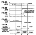
FIGS. 2A to 2E are state transition diagrams of theengine 1, the first clutch CL1 and the motor/generator 2 of the hybrid vehicle shown inFIG. 1 . In the drawings, each lateral axis indicates time, and each vertical axis indicates a system condition of the hybrid vehicle. First, at time t1, a shift signal to shift from the current gear position (Current GP) to the next gear position (Next GP) is detected. This can be, for example, judgment of a [2nd → 1st] downshift. Also at time t1, controlling of engaging oil pressures of the engaging elements on a disengaging side (dotted line inFIG. 2E ) and an engaging side (bold line inFIG. 2E ) of the second clutch CL2 of the automatic transmission AT is started. At this time point, thetransmission 3 is in a torque phase, and theengine 1 and the motor/generator 2 are torque-controlled. In the time period from t1 to t2, the engaging oil pressure of the engaging elements on the disengaging side of the second clutch CL2 is decreased, and the engaging oil pressure of the engaging elements on the engaging side of the second clutch CL2 is increased. - Subsequently, at time t2, the engaging oil pressure of the engaging elements on the engaging side becomes constant, and the phase shifts to an inertia phase. The control shifts to a rotation speed control by a target rotation speed, and the first clutch CL1 is disengaged at time t2 or shortly thereafter. By the disengaging of the first clutch CL1, the engine friction becomes substantially equal to zero, and the MG assist torque is input to the
automatic transmission 3 input torque until the motor/generator 2 is controlled. Then, since an output torque is controlled or adjusted to a torque equivalent to a target driving torque from time t3 at which the engaging pressure of the engaging elements on the engaging side is increased and the phase becomes the torque phase again, there is no occurrence of the torque change of the output torque caused by the disengagement of the first clutch CL1. That is, in the present embodiment, the disengagement of the first clutch CL1 is performed between time t1 and time t3 at the time of the downshift, more specifically, during the rotation speed control between time t2 and time t3. -
FIG. 3 is a flow chart showing one example of control executed by thecontroller 9 ofFIG. 1 .. As shown in the drawing, at step S11, a judgment is made as to whether or not a measured current SOC (value expressing a state of charge of the battery or a charge amount of the battery) is smaller than a predetermined threshold value. If the current SOC is not smaller than the predetermined threshold value, the routine is terminated. If the current SOC is smaller than the predetermined threshold value, at step S12, a judgment is made as to whether or not the vehicle operation is in coasting deceleration with the first clutch CL1 engaged. More specifically, the judgment whether the first clutch CL1 is engaged can be made by information obtained from theclutch control section 9a. The judgment whether the vehicle operation is in the coasting deceleration can be made by information obtained from theaccelerator position sensor 7. At step S12, on the basis of the information obtained from theseclutch control section 9a andaccelerator position sensor 7, the judgment is made as to whether or not the vehicle operation is in the coasting deceleration with the first clutch CL1 engaged. If the judgment condition is not satisfied, the engagement of the first clutch CL1 is maintained, and the routine is terminated. If the judgment condition is satisfied, at step S13, a judgment is made as to whether or not a current vehicle speed is smaller than or equal to a downshift vehicle speed (for example a current vehicle speed ≤ 2nd → 1st downshift vehicle speed). Step S13 is repeated until the current vehicle speed is smaller than or equal to the downshift vehicle speed as a result of the coasting deceleration. When the current vehicle speed becomes smaller than or equal to the downshift vehicle speed, at step S14, downshift is started (from, for example 2nd → 1st). At step S15, the rotation speed control is initiated, and at step S16, the disengagement of the first clutch CL1 is performed. At step S17, the downshift is completed, and the control shifts to torque control. Afterwards, the vehicle drive shifts to a creep EV drive. With this operation, since the excessive deceleration caused by the engine dragging can be prevented, the improvement of the fuel economy can be achieved and also undesirable vehicle behavior resulting from the clutch disengagement can be suppressed. - To aid the understanding of the invention, each scenario of clutch engagement and disengagement of the hybrid vehicle having the first and second clutches CL1, CL2 shown in
FIG. 1 is explained. As shown inFIGS. 4A and 4B , this hybrid vehicle has theengine 1, the first clutch CL1, the second clutch CL2, the motor/generator 2, theinverter 12 and thebattery 10. In the following drawings as well, the same component is denoted by the same reference sign. At a stop state, the first clutch CL1 is disengaged, and the second clutch CL2 is engaged. During acceleration, DC power of thebattery 10 is converted to three-phase AC current through theinverter 12 to rotate the motor/generator 2; a driving force produced by this rotation is then transmitted to the driving wheel via the second clutch CL2. -
FIGS. 4A and 4B explain the clutch engagement and disengagement in operating conditions from a constant speed (FIG. 4A ) to deceleration (FIG. 4B ). As shown inFIG. 4A , the vehicle is in a state in which each of the first and second clutches CL1, CL2 is completely engaged. The vehicle travels at the constant speed with an engine torque transmitted to the driving wheel through the first clutch CL1, the motor/generator 2 and the second clutch CL2. As a matter of course, since the vehicle is a hybrid vehicle, at this time a motor torque can be supplied besides the engine torque, or the vehicle could travel by only the motor torque with the fuel supply to the engine side stopped. As shown inFIG. 4B , when the accelerator pedal is released from such constant speed, in a case where the SOC is in a normal condition the drive shifts to the coasting drive in the EV mode. The first clutch CL1 is disengaged, and the motor/generator 2 works as a power generator. The AC power is converted to DC power through theinverter 12 and charges thebattery 10. That is to say, at deceleration, a regenerative operation in which thebattery 10 is charged is operated. -
FIGS. 5A and 5B explain the clutch engagement and disengagement in operating conditions where the drive shifts to the coasting operation in the engine brake drive mode under a high SOC state during deceleration.FIG. 5A is the coasting drive in the EV mode explained above inFIG. 4B . In a case where thebattery 10 is in the high SOC state (a fully charged condition and a charge prohibition state) in which the SOC exceeds the specified threshold charge value when the regenerative operation to thebattery 10 is operated while being decelerated or when the accelerator pedal is released, in order to perform the deceleration without regenerating the power to thebattery 10, as shown inFIG. 5B , the drive shifts to the coasting drive in the engine brake drive mode. The first clutch CL1 is engaged, and the operation in which the engine is dragged with no fuel supply to theengine 1 is carried out. That is to say, the coasting drive is performed by the engine brake. -
FIGS. 6A through 6D explain the clutch engagement and disengagement in operating conditions where the operation shifts from the coasting drive in the engine brake drive mode at the high SOC to the deceleration (downshift) or to re-acceleration.FIG. 6A is the coasting drive in the engine brake drive mode explained above inFIG. 5B . At the coasting drive in the engine brake drive mode shown inFIG. 6A , the downshift occurs in accordance with the decrease of the vehicle speed. According to an ordinary downshift technique,FIG. 6A changes toFIG. 6B by the deceleration, and the shift position downshifts to a low speed shift position of high deceleration, thus an over-deceleration state arises. On the other hand, according to embodiments of the invention, since the first clutch CL1 is disengaged during the downshift as shown inFIG. 6B , shock of the disengagement can be lessened. Furthermore, since an engagement or connection with the engine, which causes the over-deceleration, is released, there is no over-deceleration. Moreover, in such scenes, re-acceleration is often performed. In this case, as shown inFIG. 6D , the drive can shift to the EV drive without additional clutch control. - Modifications and variations of the embodiments described above will occur to those skilled in the art in light of the above teachings. For instance, a function that resides in each component or each section can be rearranged within logical limits.
- In the illustrated embodiment, an operating condition where the first clutch CL1 is disengaged in synchronization with the downshift from 2nd → 1st is explained. However, the invention is not limited to this situation. For instance, where the transmission ratio of the 2nd shift position is sufficiently high, the first clutch CL1 could be disengaged in synchronization with the downshift of 3rd → 2nd, and even in this case, the same effects as the above embodiments can be obtained. Furthermore, in a case where a correspondence between the vehicle speed and the downshift is correctly or exactly set, instead of the state of the downshift, it could be possible that the first clutch CL1 is disengaged in synchronization with the vehicle speed by which the downshift is performed.
- The above described embodiments have been described in order to allow easy understanding of the present invention, and do not limit the present invention. On the contrary, the invention is intended to cover various modifications and equivalent arrangements included within the scope of the appended claims, which scope is to be accorded the broadest interpretation so as to encompass all such modifications and equivalent structures as is permitted under the law.
Claims (8)
- A control apparatus for a hybrid vehicle including an engine (1), a motor/generator (2), a first clutch (CL1) that transmits and disconnect torque between the engine (1) and the motor/generator (2) by engagement and disengagement of the first clutch (CL1) and an automatic transmission (3) disposed between the motor/generator (2) and a driving wheel (6), the control apparatus comprising:
a controller (9) configured:
to maintain engagement of the first clutch (CL1) to perform a vehicle coasting drive while dragging the engine (1) at a time of coasting deceleration, characterized in that the controller (9) is configured:to control the automatic transmission (3) to perform a downshift process including a first torque phase, during which the controller (9) executes a first torque control of the motor/generator (2), an inertia phase, during which the controller (9) executes a rotation speed control of the motor/generator (2), and a second torque control phase, during which the controller (9) performs a second torque control of the motor/generator (2);to disengage the first clutch (CL1) during the downshift process in response to switching from the first torque control to the rotation speed control; andto maintain disengagement of the first clutch (CL1) and shift from the rotation speed control of the motor/generator (2) to the second torque control of the motor/generator (2) after the inertia phase is completed and the second torque phase begins. - The control apparatus according to claim 1 wherein the hybrid vehicle includes a battery (10) that supplies the motor/generator (2) with power and is charged with power generated by the motor/generator (2); and wherein:
the controller (9) is further configured to perform the vehicle coasting drive while dragging the engine (1) at the time of coasting deceleration when a state of charge of the battery (10) charge is greater than a predetermined threshold charge value. - The control apparatus according to claim 1 or claim 2, wherein:
the controller (9) is further configured to control the automatic transmission (3) to perform the downshift process in accordance with a decrease of a vehicle speed. - The control apparatus according to claim 3, wherein:
the controller (9) is further configured to disengage the first clutch (CL1) during the downshift process when the automatic transmission (3) downshifts to a shift position of a largest transmission ratio in accordance with the decrease of the vehicle speed at the vehicle coasting drive in which the engine is dragged with the first clutch engaged. - A method of controlling a hybrid vehicle including an engine (1), a motor/generator (2), a first clutch (CL1) that transmits and disconnects torque between the engine (1) and the motor/generator (2) by engagement and disengagement of the first clutch (CL1) and an automatic transmission (3) disposed between the motor/generator (2) and a driving wheel (6), the method comprising:maintaining engagement of the first clutch (CL1) to perform a vehicle coasting drive while dragging the engine (1) at a time of coasting deceleration, characterized bycontrolling the automatic transmission (3) to perform a downshift process including;executing a first torque phase by controlling a torque of the motor/generator (2);executing an inertia phase by controlling a rotation speed of the motor/generator (2) after executing the first torque phase; andexecuting a second torque control phase by controlling the torque of the motor/generator (2) after executing the inertia phase;disengaging the first clutch (CL1) during the downshift process responsive to switching from the first torque phase to the inertia phase; andmaintaining disengagement of the first clutch (CL1) after the second torque phase begins.
- The method according to claim 5 wherein the hybrid vehicle includes a battery (10) that supplies the motor/generator (2) with power and is charged with power generated by the motor/generator (2), the method further comprising:
performing the vehicle coasting drive while dragging the engine (1) at the time of coasting deceleration when a state of charge of the battery charge is greater than a predetermined threshold charge value. - The method according to claim 5 or claim 6 wherein controlling the automatic transmission (3) to perform the downshift process occurs in accordance with a decrease of a vehicle speed.
- The method according to claim 7 wherein disengaging the first clutch (CL1) during the downshift process occurs when the automatic transmission (3) downshifts to a shift position of a largest transmission ratio in accordance with the decrease of the vehicle speed at the vehicle coasting drive in which the engine is dragged with the first clutch (CL1) engaged.
Applications Claiming Priority (2)
| Application Number | Priority Date | Filing Date | Title |
|---|---|---|---|
| JP2008052428A JP4743218B2 (en) | 2008-03-03 | 2008-03-03 | Clutch control device for hybrid vehicle |
| PCT/IB2009/000374 WO2009109825A1 (en) | 2008-03-03 | 2009-02-27 | Control apparatus and method for controlling a hybrid vehicle |
Publications (3)
| Publication Number | Publication Date |
|---|---|
| EP2247480A1 EP2247480A1 (en) | 2010-11-10 |
| EP2247480A4 EP2247480A4 (en) | 2018-05-16 |
| EP2247480B1 true EP2247480B1 (en) | 2020-02-12 |
Family
ID=41055589
Family Applications (1)
| Application Number | Title | Priority Date | Filing Date |
|---|---|---|---|
| EP09717672.1A Active EP2247480B1 (en) | 2008-03-03 | 2009-02-27 | Control apparatus and method for controlling a hybrid vehicle |
Country Status (5)
| Country | Link |
|---|---|
| US (1) | US8491442B2 (en) |
| EP (1) | EP2247480B1 (en) |
| JP (1) | JP4743218B2 (en) |
| CN (1) | CN101959731B (en) |
| WO (1) | WO2009109825A1 (en) |
Families Citing this family (62)
| Publication number | Priority date | Publication date | Assignee | Title |
|---|---|---|---|---|
| JP5680279B2 (en) | 2008-03-06 | 2015-03-04 | 日産自動車株式会社 | Engine stop control device for hybrid vehicle |
| US9242545B2 (en) | 2010-10-20 | 2016-01-26 | GM Global Technology Operations LLC | Negative-torque downshift execution for fixed-gear transmissions |
| JPWO2012053607A1 (en) * | 2010-10-22 | 2014-02-24 | 日野自動車株式会社 | Vehicle, control method, and program |
| JP5477319B2 (en) * | 2011-03-25 | 2014-04-23 | アイシン・エィ・ダブリュ株式会社 | Control device for hybrid drive |
| DE102011102332B3 (en) * | 2011-05-25 | 2012-10-25 | Audi Ag | Method for operating a longitudinal driver assistance system in a motor vehicle and motor vehicle |
| KR20130030507A (en) * | 2011-09-19 | 2013-03-27 | 현대자동차주식회사 | Coasting control method for hybrid vehicle with amt |
| JP6100690B2 (en) * | 2011-09-27 | 2017-03-22 | トヨタ自動車株式会社 | vehicle |
| DE102011055085A1 (en) * | 2011-11-07 | 2013-05-08 | Dr. Ing. H.C. F. Porsche Aktiengesellschaft | A hybrid powertrain and method for controlling a hybrid powertrain |
| JP5927895B2 (en) | 2011-12-16 | 2016-06-01 | アイシン精機株式会社 | Control device for drive device for hybrid vehicle |
| WO2013088577A1 (en) * | 2011-12-16 | 2013-06-20 | トヨタ自動車株式会社 | Vehicle control device |
| WO2013137080A1 (en) * | 2012-03-13 | 2013-09-19 | 日産自動車株式会社 | Hybrid vehicle control apparatus |
| JP6053099B2 (en) * | 2012-03-23 | 2016-12-27 | 本田技研工業株式会社 | Drive control apparatus for hybrid vehicle |
| JP5874813B2 (en) * | 2012-03-26 | 2016-03-02 | トヨタ自動車株式会社 | Drive control apparatus for hybrid vehicle |
| JP2015116832A (en) * | 2012-04-06 | 2015-06-25 | 日産自動車株式会社 | Hybrid-vehicular control apparatus |
| JP2013216285A (en) * | 2012-04-12 | 2013-10-24 | Honda Motor Co Ltd | Control device of vehicle drive device |
| US8666577B2 (en) | 2012-04-26 | 2014-03-04 | Ford Global Technologies, Llc | Economic cruise control |
| US9108632B2 (en) | 2012-05-04 | 2015-08-18 | Ford Global Technologies, Llc | Methods and systems for operating a driveline clutch |
| US9650036B2 (en) | 2012-05-04 | 2017-05-16 | Ford Global Technologies, Llc | Methods and systems for adjusting cylinder air charge |
| US9068546B2 (en) | 2012-05-04 | 2015-06-30 | Ford Global Technologies, Llc | Methods and systems for engine cranking |
| US8882634B2 (en) | 2012-05-04 | 2014-11-11 | Ford Global Technologies, Llc | Methods and systems for operating a vehicle driveline responsive to external conditions |
| US9039570B2 (en) | 2012-05-04 | 2015-05-26 | Ford Global Technologies, Llc | Methods and systems for adjusting driveline disconnect clutch operation |
| US9322380B2 (en) | 2012-05-04 | 2016-04-26 | Ford Global Technologies, Llc | Methods and systems for engine starting during a shift |
| US8998771B2 (en) | 2012-05-04 | 2015-04-07 | Ford Global Technologies, Llc | Methods and systems for a vehicle driveline |
| DE102013208016A1 (en) * | 2012-05-04 | 2013-11-07 | Ford Global Technologies, Llc | Method of adapting operation of hybrid vehicle powertrain, involves providing manual driving input for powertrain operation mode parameter and adjusting operation of powertrain disengaging clutch in response to operation mode parameter |
| US9656665B2 (en) | 2012-05-04 | 2017-05-23 | Ford Global Technologies, Llc | Methods and systems for a driveline dual mass flywheel |
| US9278692B2 (en) | 2012-05-04 | 2016-03-08 | Ford Global Technologies, Llc | Methods and systems for a four wheel drive vehicle driveline |
| US8892289B2 (en) | 2012-05-04 | 2014-11-18 | Ford Global Technologies, Llc | Methods and systems for operating a vehicle driveline |
| US8740744B2 (en) * | 2012-05-07 | 2014-06-03 | Ford Global Technologies, Llc | Adjusting motor torque to compensate for uphill and downhill demands during cruise control in hybrid vehicle |
| US9221451B2 (en) * | 2012-05-17 | 2015-12-29 | Toyota Motor Engineering & Manufacturing North America, Inc. | Systems and methods for increasing fuel efficiency |
| KR101811975B1 (en) | 2012-09-24 | 2018-01-25 | 가부시끼 가이샤 구보다 | Vehicle |
| JP6065812B2 (en) * | 2012-11-01 | 2017-01-25 | トヨタ自動車株式会社 | Control device for hybrid vehicle |
| JP2014104776A (en) * | 2012-11-24 | 2014-06-09 | Toyota Motor Corp | Control unit of hybrid vehicle |
| GB2508670A (en) * | 2012-12-10 | 2014-06-11 | Jaguar Land Rover Ltd | Hybrid vehicle and boost control for gradients |
| KR101526384B1 (en) * | 2013-03-26 | 2015-06-05 | 현대자동차 주식회사 | Engine clutch control system for hybrid vehicle and method thereof |
| JP2014213748A (en) * | 2013-04-25 | 2014-11-17 | アイシン精機株式会社 | Vehicle control device |
| WO2015130614A1 (en) * | 2014-02-25 | 2015-09-03 | Cummins, Inc. | Power regeneration optimization in a hybrid vehicle |
| SE539477C2 (en) * | 2014-07-07 | 2017-09-26 | Scania Cv Ab | Control of an internal combustion engine in connection with freewheeling |
| SE539479C2 (en) * | 2014-07-07 | 2017-09-26 | Scania Cv Ab | Control of an internal combustion engine in connection with freewheeling |
| US9452748B2 (en) * | 2014-07-31 | 2016-09-27 | Ford Global Technologies, Llc | Methods and systems for improving hybrid vehicle transmission shifting |
| US20160101770A1 (en) * | 2014-10-10 | 2016-04-14 | Ford Global Technologies, Llc | Methods and Systems of Controlling A Vehicle Powertrain |
| US9399454B2 (en) * | 2014-11-21 | 2016-07-26 | GM Global Technology Operations LLC | Transmission with electronic range selector and pull out of park control logic |
| EP3954917B1 (en) * | 2015-02-25 | 2023-05-03 | Denso Corporation | Vehicle control device for controlling inertia operation of vehicle |
| JP6565699B2 (en) * | 2015-02-25 | 2019-08-28 | 株式会社デンソー | Vehicle control device |
| EP3265335B1 (en) * | 2015-03-03 | 2018-10-24 | Volvo Truck Corporation | A method of controlling a vehicle |
| JP6241438B2 (en) * | 2015-03-11 | 2017-12-06 | トヨタ自動車株式会社 | Control device for hybrid vehicle |
| FR3035845B1 (en) * | 2015-05-07 | 2018-10-19 | Psa Automobiles Sa. | METHOD FOR CONTROLLING THE THERMAL MOTOR OF A HYBRID VEHICLE FOR A VEHICLE DECELERATION PHASE |
| JP6106215B2 (en) * | 2015-06-18 | 2017-03-29 | 富士重工業株式会社 | Vehicle control device |
| GB2543043A (en) * | 2015-10-05 | 2017-04-12 | Gm Global Tech Operations Llc | Vehicle power system |
| CN106895142B (en) * | 2015-12-18 | 2019-05-10 | 上海汽车集团股份有限公司 | Gear box control unit and its shift fork and clutch cooperative control method |
| US10160440B2 (en) * | 2016-06-16 | 2018-12-25 | Ford Global Technologies, Llc | Methods and system for controlling driveline torque |
| KR101836675B1 (en) * | 2016-07-29 | 2018-04-20 | 현대자동차주식회사 | Control method for coasting of automotive |
| KR20180067984A (en) * | 2016-12-13 | 2018-06-21 | 현대자동차주식회사 | Method and apparatus for controlling mhsg of mild hybrid electric vehicle |
| DE102017100988A1 (en) * | 2017-01-19 | 2018-07-19 | Schaeffler Technologies AG & Co. KG | Method for controlling a sailing operation of a vehicle with automated clutch |
| JP6780610B2 (en) * | 2017-08-22 | 2020-11-04 | トヨタ自動車株式会社 | Vehicle control device |
| EP3725621B1 (en) * | 2017-12-15 | 2021-11-03 | Nissan Motor Co., Ltd. | Control method for hybrid vehicle and control apparatus for hybrid vehicle |
| CN113195320B (en) * | 2019-01-09 | 2024-04-05 | 舍弗勒技术股份两合公司 | Coasting downshift control method and control system |
| JP6994007B2 (en) * | 2019-07-01 | 2022-02-03 | 本田技研工業株式会社 | Vehicle control device |
| JP7352453B2 (en) * | 2019-11-26 | 2023-09-28 | 株式会社Subaru | Vehicle controls and vehicles |
| CN114320631B (en) * | 2020-09-25 | 2023-03-21 | 上海汽车集团股份有限公司 | Starting method of hybrid electric vehicle and hybrid electric vehicle |
| US11718298B2 (en) * | 2020-10-21 | 2023-08-08 | Cummins Inc. | Methods and systems for coordinating predictive cruise control, engine-off coasting, and hybrid power split |
| CN112984099B (en) * | 2021-05-08 | 2021-07-27 | 北京航空航天大学 | Gear shifting control method for changing intention in unpowered gear-up process |
| CN113147727B (en) * | 2021-06-04 | 2022-09-02 | 一汽解放青岛汽车有限公司 | Energy recovery control method for hybrid vehicle, and storage medium |
Citations (2)
| Publication number | Priority date | Publication date | Assignee | Title |
|---|---|---|---|---|
| US5993350A (en) * | 1997-12-01 | 1999-11-30 | Lawrie; Robert E. | Automated manual transmission clutch controller |
| DE102006003725A1 (en) * | 2006-01-26 | 2007-08-02 | Zf Friedrichshafen Ag | Transmission train for a hybrid vehicle, with an internal combustion motor and an electromotor, gives an accelerated synchronizing of the target gear on a gear change |
Family Cites Families (11)
| Publication number | Priority date | Publication date | Assignee | Title |
|---|---|---|---|---|
| DE3335923A1 (en) | 1983-03-07 | 1984-09-13 | Volkswagenwerk Ag | Hybrid drive arrangement |
| JP3861510B2 (en) * | 1999-04-28 | 2006-12-20 | トヨタ自動車株式会社 | Drive control device |
| JP3906604B2 (en) * | 1999-05-12 | 2007-04-18 | トヨタ自動車株式会社 | Vehicle drive control device |
| JP2002144921A (en) | 2000-11-15 | 2002-05-22 | Mitsubishi Motors Corp | Control system for hybrid vehicle |
| JP2004162534A (en) | 2002-11-11 | 2004-06-10 | Nissan Motor Co Ltd | Driving control device of hybrid car |
| JP3843935B2 (en) * | 2002-11-21 | 2006-11-08 | トヨタ自動車株式会社 | Vehicle drive control device |
| DE102004002061A1 (en) | 2004-01-15 | 2005-08-04 | Zf Friedrichshafen Ag | Method for controlling and regulating a drive train of a hybrid vehicle and drive train of a hybrid vehicle |
| JP4265568B2 (en) | 2005-04-28 | 2009-05-20 | 日産自動車株式会社 | Mode transition control device for hybrid vehicle |
| DE102006031684A1 (en) * | 2006-07-08 | 2008-01-10 | Zf Friedrichshafen Ag | Motor vehicle hybrid drive, with an automatic gearbox, closes the clutch between the motors when starting the combustion motor while driving with the electromotor |
| JP5742124B2 (en) * | 2010-07-21 | 2015-07-01 | 日産自動車株式会社 | Control device for hybrid vehicle |
| DE102011008597A1 (en) * | 2011-01-14 | 2012-07-19 | GM Global Technology Operations LLC (n. d. Ges. d. Staates Delaware) | Method and means for controlling the downshift |
-
2008
- 2008-03-03 JP JP2008052428A patent/JP4743218B2/en active Active
-
2009
- 2009-02-27 EP EP09717672.1A patent/EP2247480B1/en active Active
- 2009-02-27 WO PCT/IB2009/000374 patent/WO2009109825A1/en active Application Filing
- 2009-02-27 US US12/920,374 patent/US8491442B2/en active Active
- 2009-02-27 CN CN2009801076378A patent/CN101959731B/en active Active
Patent Citations (2)
| Publication number | Priority date | Publication date | Assignee | Title |
|---|---|---|---|---|
| US5993350A (en) * | 1997-12-01 | 1999-11-30 | Lawrie; Robert E. | Automated manual transmission clutch controller |
| DE102006003725A1 (en) * | 2006-01-26 | 2007-08-02 | Zf Friedrichshafen Ag | Transmission train for a hybrid vehicle, with an internal combustion motor and an electromotor, gives an accelerated synchronizing of the target gear on a gear change |
Also Published As
| Publication number | Publication date |
|---|---|
| EP2247480A1 (en) | 2010-11-10 |
| EP2247480A4 (en) | 2018-05-16 |
| JP2009208565A (en) | 2009-09-17 |
| JP4743218B2 (en) | 2011-08-10 |
| US8491442B2 (en) | 2013-07-23 |
| CN101959731B (en) | 2013-05-29 |
| CN101959731A (en) | 2011-01-26 |
| WO2009109825A1 (en) | 2009-09-11 |
| US20110174559A1 (en) | 2011-07-21 |
Similar Documents
| Publication | Publication Date | Title |
|---|---|---|
| EP2247480B1 (en) | Control apparatus and method for controlling a hybrid vehicle | |
| EP2250060B1 (en) | Control apparatus and method for controlling a hybrid vehicle | |
| US8414450B2 (en) | Control apparatus and method for controlling a hybrid vehicle | |
| EP2308734B1 (en) | Control apparatus for hybrid vehicle | |
| EP2489565B1 (en) | Control apparatus for hybrid vehicle | |
| KR101423007B1 (en) | Apparatus and method for controlling hybrid vehicle | |
| EP2639130B1 (en) | Hybrid vehicle control device | |
| EP1939059B1 (en) | Mode changeover control device for a hybrid vehicle | |
| KR101420065B1 (en) | Hybrid-vehicle control device | |
| EP2634059B1 (en) | Drive torque control device for hybrid vehicle | |
| EP2065244A2 (en) | Control apparatus of a hybrid vehicle and method for controlling the same | |
| KR101703613B1 (en) | Method and device for controlling start time of engine in hybrid vehicle | |
| JP2006306328A (en) | Mode transition controller for hybrid car | |
| JP5428330B2 (en) | Rapid deceleration control device and rapid deceleration control method for vehicle | |
| JP2012116272A (en) | Regenerative control device for hybrid electric vehicle | |
| JP5476721B2 (en) | Control device for hybrid vehicle | |
| US9321456B2 (en) | Hybrid vehicle control device | |
| KR102598558B1 (en) | Active shift control method for power-off downshift of hybrid electric vehicle | |
| JP2009292312A (en) | Cooperative control device of composite brake | |
| JP4998436B2 (en) | Control device for hybrid vehicle | |
| JP5141535B2 (en) | Control device for hybrid vehicle | |
| JP6414070B2 (en) | Hybrid vehicle drive device | |
| JP2018079877A (en) | Hybrid vehicle and control method for hybrid vehicle | |
| JP2017128281A (en) | Hybrid vehicle control device |
Legal Events
| Date | Code | Title | Description |
|---|---|---|---|
| PUAI | Public reference made under article 153(3) epc to a published international application that has entered the european phase |
Free format text: ORIGINAL CODE: 0009012 |
|
| 17P | Request for examination filed |
Effective date: 20100705 |
|
| AK | Designated contracting states |
Kind code of ref document: A1 Designated state(s): AT BE BG CH CY CZ DE DK EE ES FI FR GB GR HR HU IE IS IT LI LT LU LV MC MK MT NL NO PL PT RO SE SI SK TR |
|
| AX | Request for extension of the european patent |
Extension state: AL BA RS |
|
| DAX | Request for extension of the european patent (deleted) | ||
| RA4 | Supplementary search report drawn up and despatched (corrected) |
Effective date: 20180413 |
|
| RIC1 | Information provided on ipc code assigned before grant |
Ipc: B60W 10/08 20060101ALI20180409BHEP Ipc: B60W 10/10 20060101ALI20180409BHEP Ipc: F16H 59/44 20060101ALI20180409BHEP Ipc: F16D 48/02 20060101ALI20180409BHEP Ipc: B60W 10/02 20060101AFI20180409BHEP Ipc: B60W 10/06 20060101ALI20180409BHEP Ipc: F16H 61/68 20060101ALI20180409BHEP Ipc: F16H 61/04 20060101ALI20180409BHEP Ipc: B60L 11/14 20060101ALI20180409BHEP Ipc: F16H 63/40 20060101ALI20180409BHEP Ipc: B60W 20/00 20060101ALI20180409BHEP Ipc: B60K 6/48 20071001ALI20180409BHEP Ipc: B60K 6/547 20071001ALI20180409BHEP |
|
| RIC1 | Information provided on ipc code assigned before grant |
Ipc: B60W 10/10 20120101ALI20180409BHEP Ipc: B60K 6/547 20071001ALI20180409BHEP Ipc: B60W 10/08 20060101ALI20180409BHEP Ipc: B60W 20/00 20160101ALI20180409BHEP Ipc: F16H 63/40 20060101ALI20180409BHEP Ipc: B60K 6/48 20071001ALI20180409BHEP Ipc: F16H 61/04 20060101ALI20180409BHEP Ipc: F16D 48/02 20060101ALI20180409BHEP Ipc: F16H 59/44 20060101ALI20180409BHEP Ipc: F16H 61/68 20060101ALI20180409BHEP Ipc: B60L 11/14 20060101ALI20180409BHEP Ipc: B60W 10/06 20060101ALI20180409BHEP Ipc: B60W 10/02 20060101AFI20180409BHEP |
|
| STAA | Information on the status of an ep patent application or granted ep patent |
Free format text: STATUS: EXAMINATION IS IN PROGRESS |
|
| 17Q | First examination report despatched |
Effective date: 20190418 |
|
| RIC1 | Information provided on ipc code assigned before grant |
Ipc: B60W 10/08 20060101ALI20190816BHEP Ipc: F16H 61/04 20060101ALI20190816BHEP Ipc: B60W 10/06 20060101ALI20190816BHEP Ipc: F16H 59/44 20060101ALI20190816BHEP Ipc: F16D 48/02 20060101ALI20190816BHEP Ipc: F16H 61/68 20060101ALI20190816BHEP Ipc: B60W 10/02 20060101AFI20190816BHEP Ipc: F16H 63/40 20060101ALI20190816BHEP Ipc: B60W 20/00 20160101ALI20190816BHEP Ipc: B60K 6/48 20071001ALI20190816BHEP |
|
| GRAP | Despatch of communication of intention to grant a patent |
Free format text: ORIGINAL CODE: EPIDOSNIGR1 |
|
| STAA | Information on the status of an ep patent application or granted ep patent |
Free format text: STATUS: GRANT OF PATENT IS INTENDED |
|
| INTG | Intention to grant announced |
Effective date: 20191114 |
|
| GRAS | Grant fee paid |
Free format text: ORIGINAL CODE: EPIDOSNIGR3 |
|
| GRAA | (expected) grant |
Free format text: ORIGINAL CODE: 0009210 |
|
| STAA | Information on the status of an ep patent application or granted ep patent |
Free format text: STATUS: THE PATENT HAS BEEN GRANTED |
|
| AK | Designated contracting states |
Kind code of ref document: B1 Designated state(s): AT BE BG CH CY CZ DE DK EE ES FI FR GB GR HR HU IE IS IT LI LT LU LV MC MK MT NL NO PL PT RO SE SI SK TR |
|
| REG | Reference to a national code |
Ref country code: GB Ref legal event code: FG4D |
|
| RIN1 | Information on inventor provided before grant (corrected) |
Inventor name: SAITO, MASAKAZU Inventor name: UENO, MUNETOSHI |
|
| REG | Reference to a national code |
Ref country code: CH Ref legal event code: EP |
|
| REG | Reference to a national code |
Ref country code: AT Ref legal event code: REF Ref document number: 1231708 Country of ref document: AT Kind code of ref document: T Effective date: 20200215 |
|
| REG | Reference to a national code |
Ref country code: DE Ref legal event code: R096 Ref document number: 602009061140 Country of ref document: DE |
|
| REG | Reference to a national code |
Ref country code: IE Ref legal event code: FG4D |
|
| PG25 | Lapsed in a contracting state [announced via postgrant information from national office to epo] |
Ref country code: FI Free format text: LAPSE BECAUSE OF FAILURE TO SUBMIT A TRANSLATION OF THE DESCRIPTION OR TO PAY THE FEE WITHIN THE PRESCRIBED TIME-LIMIT Effective date: 20200212 Ref country code: NO Free format text: LAPSE BECAUSE OF FAILURE TO SUBMIT A TRANSLATION OF THE DESCRIPTION OR TO PAY THE FEE WITHIN THE PRESCRIBED TIME-LIMIT Effective date: 20200512 |
|
| REG | Reference to a national code |
Ref country code: LT Ref legal event code: MG4D |
|
| REG | Reference to a national code |
Ref country code: NL Ref legal event code: MP Effective date: 20200212 |
|
| PG25 | Lapsed in a contracting state [announced via postgrant information from national office to epo] |
Ref country code: SE Free format text: LAPSE BECAUSE OF FAILURE TO SUBMIT A TRANSLATION OF THE DESCRIPTION OR TO PAY THE FEE WITHIN THE PRESCRIBED TIME-LIMIT Effective date: 20200212 Ref country code: LV Free format text: LAPSE BECAUSE OF FAILURE TO SUBMIT A TRANSLATION OF THE DESCRIPTION OR TO PAY THE FEE WITHIN THE PRESCRIBED TIME-LIMIT Effective date: 20200212 Ref country code: BG Free format text: LAPSE BECAUSE OF FAILURE TO SUBMIT A TRANSLATION OF THE DESCRIPTION OR TO PAY THE FEE WITHIN THE PRESCRIBED TIME-LIMIT Effective date: 20200512 Ref country code: GR Free format text: LAPSE BECAUSE OF FAILURE TO SUBMIT A TRANSLATION OF THE DESCRIPTION OR TO PAY THE FEE WITHIN THE PRESCRIBED TIME-LIMIT Effective date: 20200513 Ref country code: IS Free format text: LAPSE BECAUSE OF FAILURE TO SUBMIT A TRANSLATION OF THE DESCRIPTION OR TO PAY THE FEE WITHIN THE PRESCRIBED TIME-LIMIT Effective date: 20200612 Ref country code: HR Free format text: LAPSE BECAUSE OF FAILURE TO SUBMIT A TRANSLATION OF THE DESCRIPTION OR TO PAY THE FEE WITHIN THE PRESCRIBED TIME-LIMIT Effective date: 20200212 |
|
| PG25 | Lapsed in a contracting state [announced via postgrant information from national office to epo] |
Ref country code: NL Free format text: LAPSE BECAUSE OF FAILURE TO SUBMIT A TRANSLATION OF THE DESCRIPTION OR TO PAY THE FEE WITHIN THE PRESCRIBED TIME-LIMIT Effective date: 20200212 |
|
| REG | Reference to a national code |
Ref country code: CH Ref legal event code: PL |
|
| REG | Reference to a national code |
Ref country code: BE Ref legal event code: MM Effective date: 20200229 |
|
| PG25 | Lapsed in a contracting state [announced via postgrant information from national office to epo] |
Ref country code: LT Free format text: LAPSE BECAUSE OF FAILURE TO SUBMIT A TRANSLATION OF THE DESCRIPTION OR TO PAY THE FEE WITHIN THE PRESCRIBED TIME-LIMIT Effective date: 20200212 Ref country code: EE Free format text: LAPSE BECAUSE OF FAILURE TO SUBMIT A TRANSLATION OF THE DESCRIPTION OR TO PAY THE FEE WITHIN THE PRESCRIBED TIME-LIMIT Effective date: 20200212 Ref country code: DK Free format text: LAPSE BECAUSE OF FAILURE TO SUBMIT A TRANSLATION OF THE DESCRIPTION OR TO PAY THE FEE WITHIN THE PRESCRIBED TIME-LIMIT Effective date: 20200212 Ref country code: SK Free format text: LAPSE BECAUSE OF FAILURE TO SUBMIT A TRANSLATION OF THE DESCRIPTION OR TO PAY THE FEE WITHIN THE PRESCRIBED TIME-LIMIT Effective date: 20200212 Ref country code: ES Free format text: LAPSE BECAUSE OF FAILURE TO SUBMIT A TRANSLATION OF THE DESCRIPTION OR TO PAY THE FEE WITHIN THE PRESCRIBED TIME-LIMIT Effective date: 20200212 Ref country code: LU Free format text: LAPSE BECAUSE OF NON-PAYMENT OF DUE FEES Effective date: 20200227 Ref country code: RO Free format text: LAPSE BECAUSE OF FAILURE TO SUBMIT A TRANSLATION OF THE DESCRIPTION OR TO PAY THE FEE WITHIN THE PRESCRIBED TIME-LIMIT Effective date: 20200212 Ref country code: PT Free format text: LAPSE BECAUSE OF FAILURE TO SUBMIT A TRANSLATION OF THE DESCRIPTION OR TO PAY THE FEE WITHIN THE PRESCRIBED TIME-LIMIT Effective date: 20200705 Ref country code: CZ Free format text: LAPSE BECAUSE OF FAILURE TO SUBMIT A TRANSLATION OF THE DESCRIPTION OR TO PAY THE FEE WITHIN THE PRESCRIBED TIME-LIMIT Effective date: 20200212 |
|
| REG | Reference to a national code |
Ref country code: DE Ref legal event code: R097 Ref document number: 602009061140 Country of ref document: DE |
|
| REG | Reference to a national code |
Ref country code: AT Ref legal event code: MK05 Ref document number: 1231708 Country of ref document: AT Kind code of ref document: T Effective date: 20200212 |
|
| PG25 | Lapsed in a contracting state [announced via postgrant information from national office to epo] |
Ref country code: MC Free format text: LAPSE BECAUSE OF FAILURE TO SUBMIT A TRANSLATION OF THE DESCRIPTION OR TO PAY THE FEE WITHIN THE PRESCRIBED TIME-LIMIT Effective date: 20200212 Ref country code: LI Free format text: LAPSE BECAUSE OF NON-PAYMENT OF DUE FEES Effective date: 20200229 Ref country code: CH Free format text: LAPSE BECAUSE OF NON-PAYMENT OF DUE FEES Effective date: 20200229 |
|
| PLBE | No opposition filed within time limit |
Free format text: ORIGINAL CODE: 0009261 |
|
| STAA | Information on the status of an ep patent application or granted ep patent |
Free format text: STATUS: NO OPPOSITION FILED WITHIN TIME LIMIT |
|
| 26N | No opposition filed |
Effective date: 20201113 |
|
| PG25 | Lapsed in a contracting state [announced via postgrant information from national office to epo] |
Ref country code: IT Free format text: LAPSE BECAUSE OF FAILURE TO SUBMIT A TRANSLATION OF THE DESCRIPTION OR TO PAY THE FEE WITHIN THE PRESCRIBED TIME-LIMIT Effective date: 20200212 Ref country code: IE Free format text: LAPSE BECAUSE OF NON-PAYMENT OF DUE FEES Effective date: 20200227 Ref country code: AT Free format text: LAPSE BECAUSE OF FAILURE TO SUBMIT A TRANSLATION OF THE DESCRIPTION OR TO PAY THE FEE WITHIN THE PRESCRIBED TIME-LIMIT Effective date: 20200212 |
|
| PG25 | Lapsed in a contracting state [announced via postgrant information from national office to epo] |
Ref country code: SI Free format text: LAPSE BECAUSE OF FAILURE TO SUBMIT A TRANSLATION OF THE DESCRIPTION OR TO PAY THE FEE WITHIN THE PRESCRIBED TIME-LIMIT Effective date: 20200212 Ref country code: BE Free format text: LAPSE BECAUSE OF NON-PAYMENT OF DUE FEES Effective date: 20200229 Ref country code: PL Free format text: LAPSE BECAUSE OF FAILURE TO SUBMIT A TRANSLATION OF THE DESCRIPTION OR TO PAY THE FEE WITHIN THE PRESCRIBED TIME-LIMIT Effective date: 20200212 |
|
| PG25 | Lapsed in a contracting state [announced via postgrant information from national office to epo] |
Ref country code: TR Free format text: LAPSE BECAUSE OF FAILURE TO SUBMIT A TRANSLATION OF THE DESCRIPTION OR TO PAY THE FEE WITHIN THE PRESCRIBED TIME-LIMIT Effective date: 20200212 Ref country code: MT Free format text: LAPSE BECAUSE OF FAILURE TO SUBMIT A TRANSLATION OF THE DESCRIPTION OR TO PAY THE FEE WITHIN THE PRESCRIBED TIME-LIMIT Effective date: 20200212 Ref country code: CY Free format text: LAPSE BECAUSE OF FAILURE TO SUBMIT A TRANSLATION OF THE DESCRIPTION OR TO PAY THE FEE WITHIN THE PRESCRIBED TIME-LIMIT Effective date: 20200212 |
|
| PG25 | Lapsed in a contracting state [announced via postgrant information from national office to epo] |
Ref country code: MK Free format text: LAPSE BECAUSE OF FAILURE TO SUBMIT A TRANSLATION OF THE DESCRIPTION OR TO PAY THE FEE WITHIN THE PRESCRIBED TIME-LIMIT Effective date: 20200212 |
|
| PGFP | Annual fee paid to national office [announced via postgrant information from national office to epo] |
Ref country code: FR Payment date: 20230119 Year of fee payment: 15 |
|
| PGFP | Annual fee paid to national office [announced via postgrant information from national office to epo] |
Ref country code: GB Payment date: 20230120 Year of fee payment: 15 Ref country code: DE Payment date: 20230119 Year of fee payment: 15 |