EP1894723B1 - Arrangement of blankets on printing cylinders of a printing machine. - Google Patents
Arrangement of blankets on printing cylinders of a printing machine. Download PDFInfo
- Publication number
- EP1894723B1 EP1894723B1 EP07405246A EP07405246A EP1894723B1 EP 1894723 B1 EP1894723 B1 EP 1894723B1 EP 07405246 A EP07405246 A EP 07405246A EP 07405246 A EP07405246 A EP 07405246A EP 1894723 B1 EP1894723 B1 EP 1894723B1
- Authority
- EP
- European Patent Office
- Prior art keywords
- printing
- blankets
- cylinder
- width
- cylinders
- Prior art date
- Legal status (The legal status is an assumption and is not a legal conclusion. Google has not performed a legal analysis and makes no representation as to the accuracy of the status listed.)
- Not-in-force
Links
Images

Classifications
-
- B—PERFORMING OPERATIONS; TRANSPORTING
- B41—PRINTING; LINING MACHINES; TYPEWRITERS; STAMPS
- B41F—PRINTING MACHINES OR PRESSES
- B41F30/00—Devices for attaching coverings or make-ready devices; Guiding devices for coverings
- B41F30/04—Devices for attaching coverings or make-ready devices; Guiding devices for coverings attaching to transfer cylinders
-
- B—PERFORMING OPERATIONS; TRANSPORTING
- B41—PRINTING; LINING MACHINES; TYPEWRITERS; STAMPS
- B41F—PRINTING MACHINES OR PRESSES
- B41F13/00—Common details of rotary presses or machines
- B41F13/08—Cylinders
- B41F13/193—Transfer cylinders; Offset cylinders
-
- B—PERFORMING OPERATIONS; TRANSPORTING
- B41—PRINTING; LINING MACHINES; TYPEWRITERS; STAMPS
- B41F—PRINTING MACHINES OR PRESSES
- B41F7/00—Rotary lithographic machines
- B41F7/02—Rotary lithographic machines for offset printing
- B41F7/12—Rotary lithographic machines for offset printing using two cylinders one of which serves two functions, e.g. as a transfer and impression cylinder in perfecting machines
Definitions
- the invention relates to the arrangement of printing blankets on printing cylinders of the rotary printing press in a rotary printing press.
- the rotary printing machine is preferably a web-fed printing machine.
- the machine preferably works in offset printing, either in dry offset or advantageously in wet offset.
- the machine may in particular be a newspaper printing press, preferably for the printing of large newspaper editions.
- a transfer cylinder for printing at least five pages wide having first and second mounting channels for the blankets.
- the fastening channels are arranged in different axial sections of the cylinder and offset in the circumferential direction of the cylinder by 180 ° to each other.
- printing blankets can be arranged side by side, which may have a width of one, two, three or four printing page.
- the invention is based on a rotary printing machine which comprises a first printing cylinder and a second printing cylinder, which together form a printing gap for a continuous web, preferably a paper web, and which are each covered with at least two blankets arranged axially next to one another.
- the blankets serve to transfer color to the web.
- the printing blankets preferably span the respective associated printing cylinder over its entire circumference, more precisely over almost the entire circumference. In such a blanket, the leading end and the trailing end are secured in the same nip of the associated printing cylinder.
- a plurality of printing blankets are arranged one behind the other over the circumference of one or both printing cylinders, for example two printing blankets.
- a plurality of printing blankets are arranged one behind the other over the circumference of a blanket cylinder, it is further preferred if this applies to all blankets of the respective printing cylinder arranged next to one another axially. Deviating from this, however, it would in principle be possible for a blanket in an axial section of the relevant printing cylinder to encompass its entire circumference, while in another axial section of the same printing cylinder a plurality of blankets are arranged one behind the other in the circumference.
- the axially adjacent printing blankets are preferably in abutment with one another, ie they are in contact with one another in the circumferential direction along their two mutually facing side edges, so that the gap is linear.
- the invention also requires none of the unwinding of the blankets deviating course of the side edges of the blankets, although the use of blankets with such side edges should not be excluded. In preferred embodiments, however, the blankets have side edges which are straight over their entire length and preferably extend in the circumferential direction of the respective printing cylinder.
- the blankets consist at least to a greater extent of an elastically yielding material.
- Preferred examples are the blankets known from offset printing.
- the compliant material of the blankets may be secured in the clamping channel or channels of the associated printing cylinder.
- the compliant material is on one at the periphery of the Pressure cylinder applied to the thin carrier plate applied, for example, on a metal plate, and there are the leading and the trailing end of the plate in the clamping channel or in each fixed in a different of several clamping channels.
- the invention is used with advantage in four-page-wide and six-page-wide printing cylinders, but is not limited to these width formats.
- Four-page-width printing cylinders are preferably covered with two blankets arranged axially next to one another, which, as already mentioned, preferably extend over almost the entire circumference of the printing cylinder. In principle, however, more than two printing blankets can also be arranged axially next to one another on such printing cylinders.
- Six-page-wide impression cylinder are occupied in preferred embodiments with three axially juxtaposed blankets, which preferably each extend over almost the entire circumference of the respective printing cylinder. In principle, six-page-wide printing cylinders but also more than three blankets can be arranged axially next to each other.
- only two blankets can be arranged axially next to one another on a six-page-wide printing cylinder, wherein the two blankets occupy the entire printing width in the axial direction of the cylinder. If one of the two blankets has, for example, a width of two-thirds of the entire printing width of the printing cylinder and the other of the blankets accordingly a width of one third of the entire printing width of the printing cylinder, it is sufficient for the inventive offset of the blanket column, if on the other printing cylinder, the impression gap co-forming counter-pressure cylinder, axially juxtaposed two just such blankets are arranged, wherein the arrangement is chosen so that the 1/3-wide blanket of a printing cylinder rolls on the 2/3-wide blanket of the other printing cylinder.
- the printing cylinders have axially adjacent printing sections for printing at least one printed page, for example a newspaper page. Preferably have the printing sections each the width of two printed pages.
- the axial centers of the printing blankets are offset axially relative to an axial center of the respective associated printing section.
- Such an arrangement of the blankets is advantageous, in particular, when the respective blankets, as preferred, each have at least substantially only the width of a single printing section.
- one or more of the printing blankets have either the exact width of the respectively assigned printing section or a certain oversize or undersize for the respectively assigned printing section.
- one or more of the juxtaposed blankets may also have an undersize in comparison to the width of the associated printing section, ie be narrower than the associated printing section, if the undersize is offset by an oversize in at least one other of the juxtaposed blankets.
- the axially juxtaposed blankets occupy the entire axial, usable for printing web width of the respective printing cylinder.
- the respective oversize or possibly undersize and the respective axial offset are in coordination with each other so small that none of the blanket gaps gets into one of the type area to be printed.
- the oversize or undersize is advantageously at least 1 mm and advantageously at most 20 mm, more preferably at most 15 mm.
- the blankets of at least one of the printing cylinders are all the same width.
- the blankets of the other printing cylinder can have different widths among each other.
- the uniform printing blankets may, for example, have the width of the respectively assigned printing section and the nip or the nip of the printing blankets arranged axially next to one another run exactly along a dividing line at which the respective associated printing sections adjoin one another. Because the blankets or at least one Part of the blankets of the other printing cylinder to the width of the respective associated printing section of the other printing cylinder have an oversize or undersize, results in an inventive axial offset at the same subdivision of the printing cylinder in print sections automatically.
- the blankets of the other blanket cylinder can each also have the same width each other. More preferably, the blankets of both printing cylinders are the same width. In such a constellation, the blankets are arranged on at least one of the two pressure cylinders together forming pressure cylinder axially asymmetric on the respective printing cylinder by the axial centers of these blankets are axially offset to the axial center of each associated printing section of the respective printing cylinder. If the rotary printing machine as preferred has a plurality of pairs of printing cylinders which form a printing gap in pairs and are each covered with blankets as described above, advantageously the blankets of all printing cylinders or not yet mounted blankets for all printing cylinders have the same width.
- At least one of the printing gap forming printing cylinder is covered with blankets of different widths.
- a blanket coverage is especially for wide printing cylinder in question, for example, six-page wide or eight-page wide or optionally also five- or seven-page wide printing cylinder, but in principle for narrower printing cylinder, for example, four-page wide printing cylinder.
- the other impression cylinder can be covered with mutually uniform printing blankets, as already explained in the preceding paragraph.
- the other printing cylinder can be covered with blankets of different widths.
- a printing blanket with the greater width is opposite a printing blanket with the smaller width, ie if the alternating sequence of blankets on one of the two printing cylinders is accompanied by an inversely alternating sequence on the other of the two printing cylinders.
- Such an arrangement of the blankets ensures a particularly low-vibration and therefore quiet running of the printing cylinder, while the manufacturing costs and to be operated for the storage and handling of the blankets logistical effort, on the other hand, are still limited.
- it is also preferred in the case of the second embodiments if all printing cylinders of the printing press, which in each case form a printing gap in pairs with one another, are covered with printing blankets in the same way.
- a combination of blankets is described, namely a set of blankets as such, which are intended for mounting on one or more printing cylinders of the same rotary printing press.
- the blanket set is used to equip a rotary printing machine or, if desired, only a printing cylinder of a rotary printing press according to the preferred second embodiments.
- the blanket set accordingly comprises a first blanket of a first nominal width and at least one second blanket of a second nominal width which is greater than the first nominal width.
- the nominal width is the width of the blanket before mounting on the associated impression cylinder.
- the width is accordingly measured in the unloaded state between the side edges of the resilient material of the blanket in question, as in the case of the claimed assemblies of blankets.
- the side edges extend over the entire, measured between the leading end and the trailing end of the blanket length straight and parallel to each other, in the assembled state, the two side edges within the manufacturing tolerances run exactly in the circumferential direction of the associated printing cylinder.
- the blankets of Drucktuchsets are accordingly rectangular.
- the blanket set preferably comprises a plurality of blankets of the first nominal width and a plurality of blankets of the second nominal width. Conveniently, it comprises at least as many blankets of the two different widths that with the blankets of the set a pair of printing cylinders, namely a printing cylinder and the impression cylinder, over each of the entire width of the cylinder usable for printing and over each almost the entire circumference with the blankets of the set can be occupied.
- the set advantageously comprises at least three blankets of the first width and three blankets of the second width to support at least one pair of printing cylinders, each with three blankets axially adjacent to each other and extending almost over the entire circumference of the cylinder.
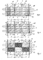
- FIG. 1 shows a first pressure cylinder 1 and a second pressure cylinder 2, which together a pressure gap 3 for a between the pressure cylinders 1 and 2 form continuous paper web, the impression cylinder 1 and 2 in FIG. 1 are offset from each other and the pressure nip 3 is therefore open.
- the printing cylinders 1 and 2 are blanket cylinders of an offset, preferably wet offset, working web-fed rotary printing press preferably for newspaper printing. The paper web is printed on both sides in the printing nip 3.
- the printing cylinders 1 and 2 are in a conventional manner with blankets 4, for example, blankets, occupied.
- the impression cylinders 1 and 2 are each four pages wide, i.
- the usable for printing bale is each so wide that the printing cylinder 1 and 2 axially next to each other four printed pages, preferably in the newspaper format, can print on the web.
- the printing cylinders 1 and 2 are each divided into two axially juxtaposed, immediately adjacent printing sections each having a width P, i. P corresponds to the width of two printed pages.
- the printing sections adjoin one another in the circumferential direction along an imaginary dividing line T.
- the width P of each of the printing sections is twice a printed page, i. it corresponds to a double page.
- FIG. 2 shows the pair of impression cylinders 1 and 2 of FIG. 1 , but with inventively arranged blankets 5, in the embodiment blankets.
- the width P of the printing sections of the printing cylinders 1 and 2 and the axial position of the printing sections have compared to the arrangement of FIG. 1 not changed.
- the Division line T runs at each of the impression cylinders 1 and 2 in the axial center about the axis of rotation.
- the blankets 5 each have the same width B.
- the width B corresponds to the printing section width P plus an excess of a few millimeters, for example 5 mm.
- two such printing blankets 5 are arranged axially next to one another and each encompassing almost the entire circumference of the associated printing cylinder 1 or 2.
- the blankets 5 of the printing cylinder 1 are offset from the dividing line T of the printing cylinder 1 to the one end face of the printing cylinder 1, while the blankets 5 of the printing cylinder 2 are offset from the dividing line T to the opposite end side.
- the offset of the blankets 5 to the respective division line T is in FIG. 2 denoted by "c". Accordingly, the blankets 5 of the printing cylinder 1 abut one another along a first gap 10a offset by c to the dividing line T and the blankets 5 of the printing cylinder 2 along a second gap 10b also offset by c toward the other end side.
- the axial offset of the two columns 10a and 10b relative to each other is thus 2c. With “e” and "d” are in FIG.
- the axially outer projections of the blankets 5 to the respective associated printing section of the printing cylinder 1 or 2 denotes.
- the offset c of the column 10a and 10b calculated on the respective division line T for example, 2 mm
- the offset of the gaps 10a and 10b relative to each other is 4 mm
- the supernatant d is in the example mentioned oversize of 5 mm 7 mm
- the Overhang e on the other side is 3 mm.
- the offset c to the respective division line T or the offset 2c of the column 10a and 10b to each other is so small that the gaps 10a and 10b outside the sentence mirror, ie the print image to be transferred, the columns 10a and 10b are axially adjacent next printed pages ,
- transitions between the axially juxtaposed Drucktüchem 5 may be sealed with a suitable mass as in the other embodiments.
- FIG. 3 shows two six-page-wide impression cylinder 11 and 12, which together form a pressure nip 3 for a passing between the printing cylinders 11 and 12, the paper web.
- the printing nip 3 is open, ie the printing cylinders 1 and 2 each occupy a parked position from the web.
- the printing cylinders 11 and 12 each have an axial bale width which corresponds to the width of six print pages which can be printed axially next to one another on the web, for example newspaper pages.
- the printing cylinders 11 and 12 are divided into three axially juxtaposed printing sections per width P. The dividing line between each two adjacent pressure sections is again denoted by T.
- FIG. 5 shows for the six-page printing cylinder 11 and 12 of the FIGS. 3 and 4 A second embodiment of the arrangement of blankets.
- Printing blankets 8 and 9 are used in two different widths E and F.
- the width E of the printing blankets 8 corresponds to the width P of the respective associated printing section.
- the narrow blankets 8 thus have an undersize.
- This undersize is compensated by a correspondingly greater width F of the blankets 9.
- the width F corresponds to the width P of the respective associated printing section plus a correspondingly larger oversize of, for example, 8 mm, that is to say an oversize 2h.
- the blankets 8 and 9 are arranged on the printing cylinders 11 and 12 in the axial direction in each case in an alternating sequence.
- a narrower blanket 8 is disposed between two wider blankets 9, while on the printing cylinder 12, a wider blanket 9 is disposed between two narrower blankets 8.
- the blankets 8 and 9 span the respective impression cylinder 11 and 12 as in the other embodiments over almost the entire circumference.
- the arrangement of the leading and trailing ends of the blankets 8 and 9 applies to the embodiment of the FIG. 4 Said in the same way.
- the respective middle blanket 8 or 9 is arranged axially centrally on the respective printing cylinder 11 or 12. Accordingly, the two outer blankets 8 or 9 are arranged axially asymmetrically.
- the gaps 10a formed between each two axially juxtaposed printing blankets 8 and 9 therefore extend on the respective division line T.
- the gaps 10b of the printing cylinder 12 each have an axial offset h relative to the gaps 10a and the dividing lines T. half excess of the wider blankets 9 corresponds.
- the axial offset h between the next adjacent columns 10a and 10b is the same. He is also in the embodiment of FIG. 5 4 mm by way of example.
- Each of the printing cylinders 1 and 2 and the printing cylinders 11 and 12 transmits a printed image obtained from a respectively subsequent forme cylinder to the web.
- Each of the forme cylinders has an inking unit and, if the press works in wet offset, a dampening unit downstream.
- the two printing units of the printing cylinder 1 and 2 on the one hand and the printing cylinder 11 and 12 on the other hand together form a printing unit having in a side view, for example, the shape of a "V" or an inverted "V".
Landscapes
- Engineering & Computer Science (AREA)
- Mechanical Engineering (AREA)
- Rotary Presses (AREA)
- Perforating, Stamping-Out Or Severing By Means Other Than Cutting (AREA)
- Screen Printers (AREA)
Abstract
Description
Die Erfindung betrifft bei einer Rotationsdruckmaschine die Anordnung von Drucktüchern auf Druckzylindern der Rotationsdruckmaschine. Die Rotationsdruckmaschine ist vorzugsweise eine Rollendruckmaschine. Bevorzugt arbeitet die Maschine im Offsetdruck, entweder im Trockenoffset oder vorteilhafterweise im Nassoffset. Bei der Maschine kann es sich insbesondere um eine Zeitungsdruckmaschine, vorzugsweise für den Druck großer Zeitungsauflagen handeln.The invention relates to the arrangement of printing blankets on printing cylinders of the rotary printing press in a rotary printing press. The rotary printing machine is preferably a web-fed printing machine. The machine preferably works in offset printing, either in dry offset or advantageously in wet offset. The machine may in particular be a newspaper printing press, preferably for the printing of large newspaper editions.
In Druckwerken, in denen mit Drucktüchem belegte Druckzylinder einen Druckspalt für eine zwischen den Druckzylindern durchlaufende Bahn bilden, können im Übergangsbereich von axial benachbarten Drucktüchern in Bahnmaterial Wellen und in der Folge Falten entstehen. Die Wellenbildung kann zu Passerproblemen führen, beispielsweise zu einem verzerrten Bild oder unleserlichen Texten. Verursacht werden die Probleme durch entweder zu stark oder zu schwach gespannte Drucktücher. Über den Umfang eines Druckzylinders zu stark gespannte Drucktücher neigen zum "Einschnüren", so dass zwischen axial benachbarten Drucktüchern eine Lücke entsteht. Eine zu geringe . Drucktuchspannung führt zu einem Überlappen der axial benachbarten Drucktücher. Beide Zustände führen im Druckspalt zweier Druckzylinder über die Bahnbreite gesehen zu lokal unterschiedlichen Wirkdurchmessern der beiden aufeinander abrollenden Druckzylinder einschließlich ihrer Drucktücher und somit zu unkontrolliertem Bahntransportverhalten.In printing units in which pressure cylinders occupied by Drucktüchem form a pressure nip for a traversing between the printing cylinders web, in the transition region of axially adjacent blankets in web material waves and wrinkles can result. The wave formation can lead to passer problems, for example to a distorted image or illegible texts. The problems are caused by either too strong or too weakly stretched blankets. Over the circumference of a printing cylinder to excessively tensioned blankets tend to "constrict", so that a gap arises between axially adjacent blankets. One too small. Blanket tension leads to an overlap of the axially adjacent blankets. Both states lead in the nip of two impression cylinders over the web width to locally different effective diameters of the two successive rolling pressure cylinder including their blankets and thus to uncontrolled web transport behavior.
Aus der
Aus der
Es ist eine Aufgabe der Erfindung, Probleme wie sie durch Einschnüren oder Überlappen von Drucktüchern entstehen können, zu beseitigen und dadurch die Druckqualität zu verbessern.It is an object of the invention to eliminate problems such as may arise from constricting or overlapping printing blankets and thereby improving print quality.
Die Erfindung geht von einer Rotationsdruckmaschine aus, die einen ersten Druckzylinder und einen zweiten Druckzylinder umfasst, die miteinander einen Druckspalt für eine durchlaufende Bahn, vorzugsweise eine Papierbahn, bilden und die jeweils mit wenigstens zwei axial nebeneinander angeordneten Drucktüchern belegt sind. Die Drucktücher dienen der Übertragung von Farbe auf die Bahn. Die Drucktücher umspannen den jeweils zugeordneten Druckzylinder vorzugsweise über dessen gesamten Umfang, genauer gesagt über nahezu den gesamten Umfang. Bei einem derartigen Drucktuch sind das vorlaufende Ende und das nachlaufende Ende im gleichen Klemmspalt des zugeordneten Druckzylinders befestigt. Grundsätzlich ist es jedoch auch möglich, dass über den Umfang eines oder beider Druckzylinder mehrere Drucktücher hintereinander angeordnet sind, beispielsweise zwei Drucktücher. Falls über den Umfang eines Drucktuchzylinders mehrere Drucktücher hintereinander angeordnet sind, wird es ferner bevorzugt, wenn dies für alle axial nebeneinander angeordneten Drucktücher des betreffenden Druckzylinders gilt. Hiervon abweichend wäre es jedoch grundsätzlich möglich, dass ein Drucktuch in einem Axialabschnitt des betreffenden Druckzylinders dessen gesamten Umfang umspannt, während in einem anderen Axialabschnitt des gleichen Druckzylinders im Umfang hintereinander mehrere Drucktücher angeordnet sind. Die jeweils auf einem der Druckzylinder axial benachbart nebeneinander angeordneten Drucktücher bilden in einem axialen Übergangsbereich zwischen sich einen Spalt. Bevorzugt sind die axial jeweils benachbarten Drucktücher miteinander auf Stoß, d.h. sie sind in Umfangsrichtung längs ihrer beiden einander zugewandten Seitenkanten miteinander in Kontakt, so dass der Spalt linienförmig ist.The invention is based on a rotary printing machine which comprises a first printing cylinder and a second printing cylinder, which together form a printing gap for a continuous web, preferably a paper web, and which are each covered with at least two blankets arranged axially next to one another. The blankets serve to transfer color to the web. The printing blankets preferably span the respective associated printing cylinder over its entire circumference, more precisely over almost the entire circumference. In such a blanket, the leading end and the trailing end are secured in the same nip of the associated printing cylinder. In principle, however, it is also possible that a plurality of printing blankets are arranged one behind the other over the circumference of one or both printing cylinders, for example two printing blankets. If a plurality of printing blankets are arranged one behind the other over the circumference of a blanket cylinder, it is further preferred if this applies to all blankets of the respective printing cylinder arranged next to one another axially. Deviating from this, however, it would in principle be possible for a blanket in an axial section of the relevant printing cylinder to encompass its entire circumference, while in another axial section of the same printing cylinder a plurality of blankets are arranged one behind the other in the circumference. The printing blankets, each adjacent to one another axially adjacent to one of the printing cylinders, form a gap between them in an axial transition region. The axially adjacent printing blankets are preferably in abutment with one another, ie they are in contact with one another in the circumferential direction along their two mutually facing side edges, so that the gap is linear.
Nach der Erfindung weist ein in Umfangsrichtung verlaufender Spalt zwischen Drucktüchern des ersten Druckzylinders einen axialen Versatz zu einem Spalt zwischen zwei Drucktüchern des zweiten Druckzylinders auf. Auf diese Weise ist gewährleistet, dass die beiden Spalten nicht aufeinander, sondern stets nur auf dem jeweils gegenüberliegenden Drucktuch des jeweiligen Druckzylinders abrollen können. Im Druckbetrieb, wenn zwischen den beiden Druckzylindern eine zu bedruckende Bahn durchläuft, rollen die Spalte unmittelbar auf der Bahn und über die Bahn gesehen auf dem gegenüberliegenden Drucktuch ab. Die Erfindung beruht somit auf der Erkenntnis, dass aufeinander abrollende Drucktuchspalte eine wesentliche Ursache für die einleitend beschriebene Wellen- und Faltenbildung der Bahn und somit von Passerproblemen sind. Es genügt bereits ein axialer Versatz von beispielsweise einem Millimeter oder wenigen Millimetern, so dass der axiale Abstand zwischen den Satzspiegeln von zwei axial benachbarten Druckseiten vollkommen ausreicht, um die axial zueinander versetzten Spalte zwischen den benachbarten Satzspiegeln abrollen zu lassen. Da jeder der Spalte auf einem gegenüberliegend glatten Drucktuch abrollt, ist eine Faltenbildung der Bahn nicht mehr zu befürchten. Von Vorteil ist ferner, dass die Erfindung auch keines von der Abwicklungsrichtung der Drucktücher abweichenden Verlaufs der Seitenkanten der Drucktücher bedarf, obgleich die Verwendung von Drucktüchern mit derartigen Seitenkanten nicht ausgeschlossen werden soll. In bevorzugten Ausgestaltungen haben die Drucktücher jedoch Seitenkanten, die über ihre gesamte Länge gerade sind und vorzugsweise in Umfangsrichtung des jeweiligen Druckzylinders verlaufen. In derartigen Ausgestaltungen haben die Drucktücher über ihre gesamte, in Umfangsrichtung gemessene Länge je eine konstante Breite, die zwischen den parallelen Seitenkanten in Achsrichtung des zugeordneten Druckzylinders gemessen wird. Die vorlaufende Kante und die nachlaufende Kante sind vorzugsweise gerade. In derartigen Ausgestaltungen sind die Drucktücher in der Abwicklung rechteckig.According to the invention, a circumferentially extending gap between blankets of the first printing cylinder on an axial offset to a gap between two blankets of the second printing cylinder. In this way, it is ensured that the two columns can not roll on each other, but always only on the respective opposite blanket of the respective printing cylinder. In printing operation, when passing through a train to be printed between the two printing cylinders, the gaps roll directly on the web and across the web on the opposite blanket. The invention is thus based on the recognition that mutually rolling blanket gaps are a major cause of the initially described wave and wrinkling of the web and thus of passer problems. An axial offset of, for example, one millimeter or a few millimeters already suffices, so that the axial distance between the set levels of two axially adjacent print sides is completely sufficient to allow the axially offset gaps to roll between the adjacent typesetting mirrors. Since each of the column rolls on an opposite smooth blanket, a wrinkling of the web is no longer to be feared. A further advantage is that the invention also requires none of the unwinding of the blankets deviating course of the side edges of the blankets, although the use of blankets with such side edges should not be excluded. In preferred embodiments, however, the blankets have side edges which are straight over their entire length and preferably extend in the circumferential direction of the respective printing cylinder. In such embodiments, the blankets each have a constant width over their entire length measured in the circumferential direction, which is measured between the parallel side edges in the axial direction of the associated printing cylinder. The leading edge and the trailing edge are preferably straight. In such embodiments, the blankets in the settlement are rectangular.
Die Drucktücher bestehen zumindest zu einem größeren Teil aus einem elastisch nachgiebigen Material. Bevorzugte Beispiele sind die aus dem Offsetdruck bekannten Gummitücher. Das nachgiebige Material der Drucktücher kann in dem Klemmkanal oder den mehreren Klemmkanälen des zugeordneten Druckzylinders befestigt sein. Vorzugsweise ist das nachgiebige Material jedoch auf einer an den Umfang des Druckzylinders anlegbaren dünnen Trägerplatte aufgebracht, beispielsweise auf eine Metallplatte, und es sind das vorlaufende und das nachlaufende Ende der Platte in dem Klemmkanal oder je in einem anderen von mehreren Klemmkanälen befestigt.The blankets consist at least to a greater extent of an elastically yielding material. Preferred examples are the blankets known from offset printing. The compliant material of the blankets may be secured in the clamping channel or channels of the associated printing cylinder. Preferably, however, the compliant material is on one at the periphery of the Pressure cylinder applied to the thin carrier plate applied, for example, on a metal plate, and there are the leading and the trailing end of the plate in the clamping channel or in each fixed in a different of several clamping channels.
Die Erfindung kommt mit Vorteil bei vierseitenbreiten und sechsseitenbreiten Druckzylindern zum Einsatz, ist auf diese Breitenformate jedoch nicht beschränkt. Vierseitenbreite Druckzylinder sind vorzugsweise mit zwei axial nebeneinander angeordneten Drucktüchern belegt, die sich wie bereits erwähnt vorzugsweise über nahezu den gesamten Umfang des Druckzylinders erstrecken. Auf derartigen Druckzylindern können grundsätzlich aber auch mehr als zwei Drucktücher axial nebeneinander angeordnet sei. Sechsseitenbreite Druckzylinder sind in bevorzugten Ausgestaltungen mit drei axial nebeneinander angeordneten Drucktüchern belegt, die sich vorzugsweise je über nahezu den gesamten Umfang des betreffenden Druckzylinders erstrecken. Grundsätzlich können auf sechsseitenbreiten Druckzylindern aber auch mehr als drei Drucktücher axial nebeneinander angeordnet sein. Desweiteren können alternativ auch nur zwei Drucktücher axial nebeneinander auf einem sechsseitenbreiten Druckzylinder angeordnet sein, wobei die zwei Drucktücher in Achsrichtung des Zylinders dessen gesamte Druckbreite belegen. Falls das eine der zwei Drucktücher beispielsweise eine Breite von zwei Dritteln der gesamten Druckbreite des Druckzylinders und das andere der Drucktücher dementsprechend eine Breite von einem Drittel der gesamten Druckbreite des Druckzylinders hat, genügt es für den erfindungsgemäßen Versatz der Drucktuchspalte, wenn auf dem anderen Druckzylinder, dem den Druckspalt mitbildenden Gegendruckzylinder, axial nebeneinander zwei ebensolche Drucktücher angeordnet sind, wobei die Anordnung so gewählt wird, dass das 1/3-breite Drucktuch des einen Druckzylinders auf dem 2/3-breiten Drucktuch des jeweils anderen Druckzylinders abrollt. Dies bedeutet, dass in einer Draufsicht auf die beiden Druckzylinder bei dem einen der Druckzylinder das 1/3-breite Drucktuch links von der axialen Mitte des einen Druckzylinders und das 1/3-breite Drucktuch dieses Druckzylinders rechts von dessen axialen Mitte angeordnet ist.The invention is used with advantage in four-page-wide and six-page-wide printing cylinders, but is not limited to these width formats. Four-page-width printing cylinders are preferably covered with two blankets arranged axially next to one another, which, as already mentioned, preferably extend over almost the entire circumference of the printing cylinder. In principle, however, more than two printing blankets can also be arranged axially next to one another on such printing cylinders. Six-page-wide impression cylinder are occupied in preferred embodiments with three axially juxtaposed blankets, which preferably each extend over almost the entire circumference of the respective printing cylinder. In principle, six-page-wide printing cylinders but also more than three blankets can be arranged axially next to each other. Furthermore, alternatively, only two blankets can be arranged axially next to one another on a six-page-wide printing cylinder, wherein the two blankets occupy the entire printing width in the axial direction of the cylinder. If one of the two blankets has, for example, a width of two-thirds of the entire printing width of the printing cylinder and the other of the blankets accordingly a width of one third of the entire printing width of the printing cylinder, it is sufficient for the inventive offset of the blanket column, if on the other printing cylinder, the impression gap co-forming counter-pressure cylinder, axially juxtaposed two just such blankets are arranged, wherein the arrangement is chosen so that the 1/3-wide blanket of a printing cylinder rolls on the 2/3-wide blanket of the other printing cylinder. This means that in a plan view of the two printing cylinders in the one of the printing cylinder, the 1/3-wide blanket is located to the left of the axial center of a printing cylinder and the 1/3 wide blanket of this printing cylinder to the right of its axial center.
Die Druckzylinder weisen axial nebeneinander Druckabschnitte zum Drucken je wenigstens einer Druckseite auf, beispielsweise einer Zeitungsseite. Vorzugsweise haben die Druckabschnitte je die Breite von zwei Druckseiten. Auf wenigstens einem der Druckzylinder, die miteinander einen Druckspalt bilden, sind wenigstens zwei axial nebeneinander angeordnete Drucktücher, die je einen zugeordneten Druckabschnitt der mehreren Druckabschnitte des Druckzylinders belegen, axial asymmetrisch zu dem jeweils zugeordneten Druckabschnitt angeordnet. Die axialen Mitten der Drucktücher sind zu einer axialen Mitte des jeweils zugeordneten Druckabschnitts axial versetzt. Eine derartige Anordnung der Drucktücher ist vorteilhaft insbesondere dann, wenn die betreffenden Drucktücher wie bevorzugt je zumindest im Wesentlichen nur die Breite eines einzigen Druckabschnitts haben. Dies bedeutet, dass eines oder mehrere der Drucktücher entweder exakt die Breite des jeweils zugeordneten Druckabschnitts oder zu dem jeweils zugeordneten Druckabschnitt ein gewisses Übermaß oder Untermaß aufweisen. Pro Druckzylinder können sämtliche Drucktücher oder nur ein Teil der Drucktücher, gegebenenfalls auch nur eines der axial nebeneinander angeordneten Drucktücher, ein Übermaß aufweisen. Gegebenenfalls kann auch eines oder können mehrere der nebeneinander angeordneten Drucktücher auch ein Untermaß im Vergleich zu der Breite des zugeordneten Druckabschnitts haben, d.h. schmaler als der zugeordnete Druckabschnitt sein, falls das Untermaß durch ein Übermaß bei wenigstens einem anderen der nebeneinander angeordneten Drucktüchern ausgeglichen wird. Insgesamt belegen die axial nebeneinander angeordneten Drucktücher die gesamte axiale, zum Drucken nutzbare Bahnbreite des jeweiligen Druckzylinders. Das jeweilige Übermaß oder gegebenenfalls Untermaß sowie der jeweilige axiale Versatz sind in Abstimmung aufeinander so klein, dass keiner der Drucktuchspalte in einen der zu druckenden Satzspiegel gerät. Das Über- oder Untermaß beträgt vorteilhafterweise wenigstens 1 mm und vorteilhafterweise höchstens 20 mm, bevorzugter höchstens 15 mm.The printing cylinders have axially adjacent printing sections for printing at least one printed page, for example a newspaper page. Preferably have the printing sections each the width of two printed pages. On at least one of the impression cylinders, which together form a printing nip, at least two printing blankets arranged axially next to each other, each of which occupy an associated printing section of the plurality of printing sections of the printing cylinder, are arranged axially asymmetrically with respect to the respective associated printing section. The axial centers of the printing blankets are offset axially relative to an axial center of the respective associated printing section. Such an arrangement of the blankets is advantageous, in particular, when the respective blankets, as preferred, each have at least substantially only the width of a single printing section. This means that one or more of the printing blankets have either the exact width of the respectively assigned printing section or a certain oversize or undersize for the respectively assigned printing section. Per printing cylinder all blankets or only a portion of the blankets, possibly even one of the axially juxtaposed blankets, have an excess. Optionally, one or more of the juxtaposed blankets may also have an undersize in comparison to the width of the associated printing section, ie be narrower than the associated printing section, if the undersize is offset by an oversize in at least one other of the juxtaposed blankets. Overall, the axially juxtaposed blankets occupy the entire axial, usable for printing web width of the respective printing cylinder. The respective oversize or possibly undersize and the respective axial offset are in coordination with each other so small that none of the blanket gaps gets into one of the type area to be printed. The oversize or undersize is advantageously at least 1 mm and advantageously at most 20 mm, more preferably at most 15 mm.
In bevorzugten ersten Ausgestaltungen sind die Drucktücher von wenigstens einem der Druckzylinder alle gleich breit. Die Drucktücher des anderen Druckzylinders können untereinander unterschiedliche Breiten aufweisen. In solch einer Konstellation können die gleichbreiten Drucktücher beispielsweise die Breite des jeweils zugeordneten Druckabschnitts haben und der Spalt oder die Spalte der axial benachbart nebeneinander angeordneten Drucktücher genau entlang einer Teilungslinie verlaufen, an der die jeweils zugeordneten Druckabschnitte aneinander grenzen. Da die Drucktücher oder zumindest ein Teil der Drucktücher des anderen Druckzylinders zur Breite des jeweils zugeordneten Druckabschnitts des anderen Druckzylinders ein Über- oder Untermaß aufweisen, ergibt sich ein erfindungsgemäßer Axialversatz bei gleicher Unterteilung der Druckzylinder in Druckabschnitte automatisch. Um die Herstellungskosten zu senken und die Drucktuchlogistik zu vereinfachen, können die Drucktücher des anderen Drucktuchzylinders untereinander ebenfalls je die gleiche Breite aufweisen. Bevorzugter noch sind die Drucktücher beider Druckzylinder gleichbreit. In solch einer Konstellation sind die Drucktücher auf wenigstens einem der zwei den Druckspalt miteinander bildenden Druckzylinder axial asymmetrisch auf dem betreffenden Druckzylinder angeordnet, indem die axialen Mitten dieser Drucktücher zu der axialen Mitte des jeweils zugeordneten Druckabschnitts des betreffenden Druckzylinders axial versetzt sind. Falls die Rotationsdruckmaschine wie bevorzugt eine Vielzahl von Druckzylinderpaaren aufweist, die paarweise einen Druckspalt miteinander bilden und wie vorstehend beschrieben jeweils mit Drucktüchern belegt sind, können vorteilhafterweise die Drucktücher aller Druckzylinder oder die noch nicht montierten Drucktücher für alle Druckzylinder die gleiche Breite aufweisen.In preferred first embodiments, the blankets of at least one of the printing cylinders are all the same width. The blankets of the other printing cylinder can have different widths among each other. In such a constellation, the uniform printing blankets may, for example, have the width of the respectively assigned printing section and the nip or the nip of the printing blankets arranged axially next to one another run exactly along a dividing line at which the respective associated printing sections adjoin one another. Because the blankets or at least one Part of the blankets of the other printing cylinder to the width of the respective associated printing section of the other printing cylinder have an oversize or undersize, results in an inventive axial offset at the same subdivision of the printing cylinder in print sections automatically. In order to reduce the manufacturing costs and to simplify the blanket logistics, the blankets of the other blanket cylinder can each also have the same width each other. More preferably, the blankets of both printing cylinders are the same width. In such a constellation, the blankets are arranged on at least one of the two pressure cylinders together forming pressure cylinder axially asymmetric on the respective printing cylinder by the axial centers of these blankets are axially offset to the axial center of each associated printing section of the respective printing cylinder. If the rotary printing machine as preferred has a plurality of pairs of printing cylinders which form a printing gap in pairs and are each covered with blankets as described above, advantageously the blankets of all printing cylinders or not yet mounted blankets for all printing cylinders have the same width.
In bevorzugten zweiten Ausgestaltungen ist wenigstens einer der den Druckspalt miteinander bildenden Druckzylinder mit Drucktüchern unterschiedlicher Breite belegt. Solch eine Drucktuchbelegung kommt insbesondere für breite Druckzylinder in Frage, beispielsweise sechsseitenbreite oder achtseitenbreite oder gegebenenfalls auch fünf- oder siebenseitenbreite Druckzylinder, grundsätzlich aber auch für schmalere Druckzylinder, beispielsweise vierseitenbreite Druckzylinder. Der andere Druckzylinder kann mit untereinander gleichbreiten Drucktüchern belegt sein, wie im vorstehenden Absatz bereits erläutert wurde. Vorteilhafterweise kann jedoch auch der andere Druckzylinder mit Drucktüchern unterschiedlicher Breite belegt sein. In den zweiten Ausgestaltungen sind in einer Weiterentwicklung auf wenigstens einem der Druckzylinder, die miteinander einen Druckspalt bilden, Drucktücher in genau zwei unterschiedlichen Breiten axial nebeneinander angeordnet, vorzugsweise in einer axial alternierenden Abfolge, in der auf ein breiteres der Drucktücher je ein schmaleres der Drucktücher folgt. Für derartige Ausgestaltungen wird es ferner bevorzugt, wenn auch der andere Zylinder, d.h. der Gegendruckzylinder, mit Drucktüchern in zwei unterschiedlichen Breiten belegt ist, wobei die Drucktücher unterschiedlicher Breite in axialer Richtung vorzugsweise ebenfalls alternierend angeordnet sind. Ferner wird es bevorzugt, wenn in solchen Ausgestaltungen für beide Druckzylinder Drucktücher nur in zwei unterschiedlichen Breiten verwendet werden. Hinsichtlich der alternierenden Abfolge ist es vorteilhaft, wenn einem Drucktuch mit der geringeren Breite ein Drucktuch mit der größeren Breite gegenüberliegt, d.h. wenn die alternierende Abfolge der Drucktücher auf dem einen der zwei Druckzylinder mit einer umgekehrt alternierenden Abfolge auf dem anderen der beiden Druckzylinder einhergeht. Solch eine Anordnung der Drucktücher gewährleistet einen besonders schwingungsarmen und daher ruhigen Lauf der Druckzylinder, während die Herstellungskosten und der für die Bevorratung und das Handling der Drucktücher zu betreibende logistische Aufwand sich andererseits noch in Grenzen halten. Wie bereits für die ersten Ausgestaltungen wird es auch bei den zweiten Ausgestaltungen bevorzugt, wenn alle Druckzylinder der Druckmaschine, die jeweils paarweise miteinander einen Druckspalt bilden, in gleicher Weise mit Drucktüchern belegt sind.In preferred second embodiments, at least one of the printing gap forming printing cylinder is covered with blankets of different widths. Such a blanket coverage is especially for wide printing cylinder in question, for example, six-page wide or eight-page wide or optionally also five- or seven-page wide printing cylinder, but in principle for narrower printing cylinder, for example, four-page wide printing cylinder. The other impression cylinder can be covered with mutually uniform printing blankets, as already explained in the preceding paragraph. Advantageously, however, the other printing cylinder can be covered with blankets of different widths. In the second embodiments, in a further development on at least one of the printing cylinders, which together form a printing nip, printing blankets are arranged in exactly two different widths axially next to one another, preferably in an axially alternating sequence, followed by a narrower of the blankets on a wider of the blankets , For such embodiments, it is further preferred if the other cylinder, ie the impression cylinder, is covered with blankets in two different widths, wherein the blankets of different width in the axial direction are preferably also arranged alternately. Further, it is preferred that in such embodiments for both printing cylinder blankets are used only in two different widths. With regard to the alternating sequence, it is advantageous if a printing blanket with the greater width is opposite a printing blanket with the smaller width, ie if the alternating sequence of blankets on one of the two printing cylinders is accompanied by an inversely alternating sequence on the other of the two printing cylinders. Such an arrangement of the blankets ensures a particularly low-vibration and therefore quiet running of the printing cylinder, while the manufacturing costs and to be operated for the storage and handling of the blankets logistical effort, on the other hand, are still limited. As in the case of the first embodiments, it is also preferred in the case of the second embodiments if all printing cylinders of the printing press, which in each case form a printing gap in pairs with one another, are covered with printing blankets in the same way.
Auch eine Kombination von Drucktüchern wird beschrieben, nämlich ein Set von Drucktüchern als solchen, die für eine Montage auf einem Druckzylinder oder mehreren Druckzylindern der gleichen Rotationsdruckmaschine vorgesehen sind. Das Drucktuchset wird für die Ausrüstung einer Rotationsdruckmaschine oder gegebenenfalls nur eines Druckzylinders einer Rotationsdruckmaschine nach den bevorzugten zweiten Ausgestaltungen verwendet. Das Drucktuchset umfasst dementsprechend ein erstes Drucktuch einer ersten Nennbreite und wenigstens ein zweites Drucktuch einer zweiten Nennbreite, die größer ist als die erste Nennbreite. Die Nennbreite ist die Breite des Drucktuchs vor der Montage auf dem zugeordneten Druckzylinder. Die Breite wird wie auch im Falle der beanspruchten Anordnungen von Drucktüchern dementsprechend im unbelasteten Zustand zwischen den Seitenkanten des nachgiebigen Materials des betreffenden Drucktuchs gemessen. Die Seitenkanten verlaufen über die gesamte, zwischen dem vorlaufenden Ende und dem nachlaufenden Ende des Drucktuchs gemessenen Länge gerade und parallel zueinander, im montierten Zustand verlaufen die beiden Seitenkanten innerhalb der Fertigungstoleranzen exakt in Umfangsrichtung des zugeordneten Druckzylinders. Die Drucktücher des Drucktuchsets sind dementsprechend rechteckig. Das Drucktuchset umfasst bevorzugt mehrere der Drucktücher der ersten Nennbreite und mehrere der Drucktücher der zweiten Nennbreite. Zweckmäßigerweise umfasst es zumindest soviel Drucktücher der beiden unterschiedlichen Breiten, dass mit den Drucktüchern des Sets ein Paar von Druckzylindern, nämlich ein Druckzylinder und dessen Gegendruckzylinder, über jeweils die gesamte Breite des für den Druck nutzbaren Zylinderballens und über jeweils nahezu den gesamten Umfang mit den Drucktüchern des Sets belegt werden kann. Für eine beispielsweise sechsseitenbreite Druckmaschine umfasst das Set vorteilhafterweise wenigstens drei Drucktücher der ersten Breite und drei Drucktücher der zweiten Breite, um wenigstens ein Paar von Druckzylindern mit je drei axial nebeneinander und sich nahezu über den gesamten Zylinderumfang erstreckenden Drucktüchern belegen zu können.Also, a combination of blankets is described, namely a set of blankets as such, which are intended for mounting on one or more printing cylinders of the same rotary printing press. The blanket set is used to equip a rotary printing machine or, if desired, only a printing cylinder of a rotary printing press according to the preferred second embodiments. The blanket set accordingly comprises a first blanket of a first nominal width and at least one second blanket of a second nominal width which is greater than the first nominal width. The nominal width is the width of the blanket before mounting on the associated impression cylinder. The width is accordingly measured in the unloaded state between the side edges of the resilient material of the blanket in question, as in the case of the claimed assemblies of blankets. The side edges extend over the entire, measured between the leading end and the trailing end of the blanket length straight and parallel to each other, in the assembled state, the two side edges within the manufacturing tolerances run exactly in the circumferential direction of the associated printing cylinder. The blankets of Drucktuchsets are accordingly rectangular. The blanket set preferably comprises a plurality of blankets of the first nominal width and a plurality of blankets of the second nominal width. Conveniently, it comprises at least as many blankets of the two different widths that with the blankets of the set a pair of printing cylinders, namely a printing cylinder and the impression cylinder, over each of the entire width of the cylinder usable for printing and over each almost the entire circumference with the blankets of the set can be occupied. For example, for a six-page press, the set advantageously comprises at least three blankets of the first width and three blankets of the second width to support at least one pair of printing cylinders, each with three blankets axially adjacent to each other and extending almost over the entire circumference of the cylinder.
Vorteilhafte Merkmale werden auch in den Unteransprüchen und deren Kombinationen beschrieben.Advantageous features are also described in the subclaims and their combinations.
Nachfolgend werden Ausfiihrungsbeispiele der Erfindung anhand von Figuren erläutert. An den Ausführungsbeispielen offenbar werdende Merkmale bilden je einzeln und in jeder Merkmalskombination die Gegenstände der Ansprüche und auch die vorstehend beschriebenen Ausgestaltungen vorteilhaft weiter. Es zeigen:
Figur 1- zwei vierseitenbreite Druckzylinder mit einer Anordnung von Drucktüchern nach dem Stand der Technik,
Figur 2- die vierseitenbreiten Druckzylinder der
Figur 1 mit einer erfindungsgemäßen Anordnung von Drucktüchern, Figur 3- zwei sechsseitenbreite Druckzylinder mit einer Anordnung von Drucktüchern nach dem Stand der Technik,
Figur 4- die
Druckzylinder der Figur 3 mit einer erfindungsgemäßen ersten Anordnung von Drucktüchern und Figur 5- die
Druckzylinder der Figur 3 mit einer erfindungsgemäßen zweiten Anordnung von Drucktüchern.
- FIG. 1
- two four-page wide printing cylinders with an arrangement of printing blankets according to the prior art,
- FIG. 2
- the four-page-wide printing cylinder the
FIG. 1 with an inventive arrangement of printing blankets, - FIG. 3
- two six-page wide printing cylinders with an arrangement of printing blankets according to the prior art,
- FIG. 4
- the impression cylinder the
FIG. 3 with a first arrangement of blankets according to the invention and - FIG. 5
- the impression cylinder the
FIG. 3 with a second arrangement of blankets according to the invention.
Die Druckzylinder 1 und 2 sind in herkömmlicher Weise mit Drucktüchern 4, beispielsweise Gummitüchern, belegt. Die Druckzylinder 1 und 2 sind jeweils vier Seiten breit, d.h. der für den Druck nutzbare Ballen ist jeweils so breit, dass die Druckzylinder 1 und 2 axial nebeneinander je vier Druckseiten, vorzugsweise im Zeitungsformat, auf die Bahn drucken können. Die Druckzylinder 1 und 2 sind je in zwei axial nebeneinander angeordnete, unmittelbar aneinander grenzende Druckabschnitte je einer Breite P unterteilt, d.h. P entspricht der Breite von zwei Druckseiten. Die Druckabschnitte grenzen in Umfangsrichtung längs einer gedachten Teilungslinie T aneinander. Die Breite P jedes der Druckabschnitte entspricht dem zweifachen einer Druckseite, d.h. sie entspricht einer Doppelseite.The
Auf jedem der Druckzylinder 1 und 2 sind je zwei Drucktücher 4 angeordnet. Die Drucktücher 4 weisen je eine axiale Breite A auf, die der axialen Breite P plus je einen Übermaß a entspricht. Das Übermaß a kann beispielsweise 3 mm betragen. Die Drucktücher 4 stoßen längs der Teilungslinie T aneinander und bilden um den jeweils zugeordneten Druckzylinder 1 oder 2 umlaufend radial über der Teilungslinie T je einen Spalt 10. Der Spalt 10 des Druckzylinders 1 ist axial auf der gleichen Höhe wie der Spalt 10 des Druckzylinders 2 angeordnet, so dass die beiden Spalten 10 bei einem Drehantrieb der Druckzylinder 1 und 2 und somit im Druckbetrieb über die dazwischen durchlaufende Bahn aufeinander abrollen. Die Drucktücher 4 als solche und ihre Anordnung relativ zueinander entspricht dem Stand der Technik.On each of the
Die Drucktücher 5 des Druckzylinders 1 sind gegenüber der Teilungslinie T des Druckzylinders 1 zu der einen Stirnseite des Druckzylinders 1 versetzt, während die Drucktücher 5 des Druckzylinders 2 gegenüber dessen Teilungslinie T zur gegenüberliegenden Stirnseite hin versetzt sind. Der Versatz der Drucktücher 5 zur jeweiligen Teilungslinie T ist in
Die Übergänge zwischen den axial nebeneinander angeordneten Drucktüchem 5 können wie auch bei den weiteren Ausführungsbeispielen mit einer geeigneten Masse versiegelt sein.The transitions between the axially juxtaposed
Die Breite D der Drucktücher 7 entspricht der Breite P des jeweils zugeordneten Druckabschnitts plus einen Übermaß h von einigen Millimetern, beispielsweise 4 mm. Die Drucktücher 7 des Druckzylinders 11 sind im Vergleich zu der axial symmetrischen Anordnung der
Das jeweils mittlere Drucktuch 8 oder 9 ist auf dem jeweiligen Druckzylinder 11 oder 12 axial mittig angeordnet. Entsprechend sind die beiden äußeren Drucktücher 8 oder 9 axial asymmetrisch angeordnet. Bei dem Druckzylinder 11 verlaufen die zwischen je zwei axial nebeneinander angeordneten Drucktüchern 8 und 9 gebildeten Spalte 10a daher auf der jeweiligen Teilungslinie T. Die Spalte 10b des Druckzylinders 12 weisen zu den Spalten 10a und den Teilungslinien T je einen axialen Versatz h auf, der dem halben Übermaß der breiteren Drucktücher 9 entspricht. Wie bereits im Ausführungsbeispiel der
Jeder der Druckzylinder 1 und 2 und der Druckzylinder 11 und 12 überträgt ein von einem jeweils nachgeordneten Formzylinder erhaltenes Druckbild auf die Bahn. Den Formzylindern ist je ein Farbwerk und, falls die Druckmaschine im Nassoffset arbeitet, ein Feuchtwerk nachgeordnet. Die beiden Druckwerke der Druckzylinder 1 und 2 einerseits und der Druckzylinder 11 und 12 andererseits bilden miteinander eine Druckeinheit, die in einer Seitenansicht beispielsweise die Form eines "V" oder eines auf dem Kopf stehenden "V" aufweist. Vorzugsweise umfasst die Druckmaschine mehrere solcher Druckeinheiten, die in einem Druckturm übereinander angeordnet sind, so dass die Bahn zumindest im Wesentlichen vertikal durch die Druckspalte 3 des Druckturms geführt und in den Druckspalten 3 beidseitig mehrfarbig bedruckt werden kann. In einem derartigen Druckturm sind vorzugsweise wenigstens vier solche Druckeinheiten übereinander angeordnet, so dass die Bahn in dem Druckturm beidseitig vierfarbig bedruckt werden kann. Die Druckmaschine umfasst zweckmäßigerweise mehrere solcher Drucktürme, in denen je eine Bahn beidseitig mehrfarbig bedruckt werden kann.Each of the
- 11
- Druckzylinderpressure cylinder
- 22
- Druckzylinderpressure cylinder
- 33
- Druckspaltnip
- 44
- Drucktuchblanket
- 55
- Drucktuchblanket
- 66
- Drucktuchblanket
- 77
- Drucktuchblanket
- 88th
- Drucktuchblanket
- 99
- Drucktuchblanket
- 1010
- DrucktuchspaltBlanket gap
- 10a10a
- DrucktuchspaltBlanket gap
- 10b10b
- DrucktuchspaltBlanket gap
- 1111
- Druckzylinderpressure cylinder
- 1212
- Druckzylinderpressure cylinder
- A,...,FA, ..., F
- Nennbreite des DrucktuchsNominal width of the printing blanket
- PP
- Breite des DruckabschnittsWidth of the printing section
- TT
- Teilungsliniedividing line
Claims (15)
- A rotary printing machine, comprising:a) a first printing cylinder (1; 11);b) printing blankets (5; 7; 8, 9) which are arranged axially next to each other on the first printing cylinder (1; 11) and between which a first gap (10a) is formed which extends in the circumferential direction;c) a second printing cylinder (2; 12) which together with the first printing cylinder (1; 11) forms a printing gap for a web;d) and printing blankets (5; 7; 8, 9) which are arranged axially next to each other on the second printing cylinder (2; 12) and roll off on the printing blankets (5; 7; 8, 9) of the first printing cylinder (1; 11) and between which a second gap (10b) is formed which extends in the circumferential direction,
characterised in thate) the gaps (10a, 10b) are axially offset with respect to each other, such that the first gap (10a) rolls off on one of the printing blankets (5; 7; 8, 9) of the second printing cylinder (2; 12), and the second gap (10b) rolls off on one of the printing blankets (5; 7; 8, 9) of the first printing cylinder (1; 11). - The rotary printing machine according to the preceding claim, characterised in that the printing blankets (5; 7; 8, 9) are rectangular.
- The rotary printing machine according to any one of the preceding claims, characterised in that the printing cylinders (1, 2; 11, 12) comprise printing sections (P), axially next to each other, for printing at least one printing side - preferably, exactly two printing sides - each, and in that at least two of the printing blankets (5; 7; 8, 9) of at least one of the printing cylinders (1, 2; 11, 12) each exhibit an axial centre which is axially offset with respect to an axial centre of the respectively assigned printing section (P).
- The rotary printing machine according to any one of the preceding claims, characterised in that the printing cylinders (1, 2; 11, 12) each exhibit an axial width of a number of printing sides, and the printing blankets (5; 7; 8, 9) of at least one of the printing cylinders (1, 2; 11, 12) each have a width (B, D, E, F) which at least substantially corresponds to a multiple of the width - preferably, twice the width - of one of the printing sides.
- The rotary printing machine according to any one of the preceding claims, characterised in that the printing blankets (5; 7; 8, 9) of at least one of the printing cylinders (1, 2; 11, 12) each extend over at least substantially the entire circumference of said printing cylinder.
- The rotary printing machine according to any one of the preceding claims, characterised in that the first gap (10a) is offset by at least 1 mm and at most 20 mm with respect to the second gap (10b) or the nearest of a number of second gaps (10b).
- The rotary printing machine according to any one of the preceding claims, characterised in that the printing blankets (8, 9) comprise a first printing blanket (8) with a first width (E) and a second printing blanket (9) with a second width (F) which differs from the first width (E).
- The rotary printing machine according to the preceding claim, characterised in that the printing blankets (8, 9) with the mutually differing widths (E, F) are arranged on the same printing cylinder (11, 12).
- The rotary printing machine according to any one of the preceding two claims, characterised in that the first printing blanket (8) is arranged on the first printing cylinder (11) and the second printing blanket (9) is arranged on the second printing cylinder (12), and the printing blanket (8) with the smaller width overlaps the second printing blanket (9) over at least the majority of its width (E).
- The rotary printing machine according to any one of the preceding three claims, characterised in that at least two first printing blankets (8) and one second printing blanket (9) are arranged on at least one of the printing cylinders (11, 12).
- The rotary printing machine according to any one of the preceding four claims, characterised in that the printing blankets (8, 9) with the mutually differing widths (E, F) are arranged on the first printing cylinder (11) in an axially alternating order.
- The rotary printing machine according to the preceding claim, characterised in that the printing blankets (8, 9) with the mutually differing widths (E, F) are arranged on the second printing cylinder (12), axially alternating in reverse order, such that a first printing blanket (8) arranged on the first printing cylinder (11) axially overlaps a second printing blanket (9) arranged on the second printing cylinder (12) over a predominant part of its width (E).
- The rotary printing machine according to any one of the preceding six claims, characterised in that printing blankets (8, 9) with mutually differing widths (E, F) are arranged on each of the two printing cylinders (11, 12).
- The rotary printing machine according to any one of claims 1 to 11, characterised in that the printing blankets (5; 7) of at least one of the printing cylinders (1, 2; 11, 12) each exhibit the same width (B; D).
- The rotary printing machine according to any one of claims 1 to 6 or according to claim 14, characterised in that the printing blankets (5; 7) each have the same width (B; D), and the printing blankets (5; 7) of the first printing cylinder (1; 11) are axially offset with respect to the printing blankets (5; 7) of the second printing cylinder (2; 12).
Applications Claiming Priority (1)
| Application Number | Priority Date | Filing Date | Title |
|---|---|---|---|
| DE102006040388A DE102006040388A1 (en) | 2006-08-29 | 2006-08-29 | Arrangement of printing blankets on printing cylinders of a rotary printing machine |
Publications (3)
| Publication Number | Publication Date |
|---|---|
| EP1894723A2 EP1894723A2 (en) | 2008-03-05 |
| EP1894723A3 EP1894723A3 (en) | 2009-11-04 |
| EP1894723B1 true EP1894723B1 (en) | 2012-04-25 |
Family
ID=38621061
Family Applications (1)
| Application Number | Title | Priority Date | Filing Date |
|---|---|---|---|
| EP07405246A Not-in-force EP1894723B1 (en) | 2006-08-29 | 2007-08-22 | Arrangement of blankets on printing cylinders of a printing machine. |
Country Status (3)
| Country | Link |
|---|---|
| EP (1) | EP1894723B1 (en) |
| AT (1) | ATE554928T1 (en) |
| DE (1) | DE102006040388A1 (en) |
Families Citing this family (1)
| Publication number | Priority date | Publication date | Assignee | Title |
|---|---|---|---|---|
| DE102013107995A1 (en) * | 2013-07-26 | 2015-01-29 | Manroland Web Systems Gmbh | Printing unit and contact structure for a printing unit |
Family Cites Families (10)
| Publication number | Priority date | Publication date | Assignee | Title |
|---|---|---|---|---|
| DE3336193C2 (en) * | 1983-10-05 | 1986-02-27 | M.A.N.- Roland Druckmaschinen AG, 6050 Offenbach | Blanket for a rotary offset printing press |
| DE4340915A1 (en) * | 1993-02-23 | 1994-08-25 | Heidelberger Druckmasch Ag | Interchangeable pressure sleeve |
| DE4436973C2 (en) * | 1993-12-21 | 2003-06-26 | Heidelberger Druckmasch Ag | Blanket with varying profile and process for its manufacture |
| JPH1071694A (en) * | 1996-08-30 | 1998-03-17 | Mitsubishi Heavy Ind Ltd | Printing cylinder |
| JP2927782B1 (en) * | 1998-07-23 | 1999-07-28 | 株式会社東京機械製作所 | Paper wrinkle prevention device |
| DE10000409B4 (en) * | 2000-01-07 | 2005-12-22 | Heinrich Greve Maschinen- Und Apparatebau Gmbh & Co Kg | Roller arrangement for the transport of flexible material webs |
| DE102004005893B4 (en) * | 2003-10-08 | 2010-11-04 | Koenig & Bauer Aktiengesellschaft | Elevators for a cylinder of a printing press, set of elevators and methods of making the same |
| DE102004055704B4 (en) * | 2004-11-18 | 2009-04-16 | Koenig & Bauer Aktiengesellschaft | Blankets for a blanket cylinder and a blanket cylinder of a rotary printing machine |
| DE102005062897A1 (en) * | 2005-04-02 | 2006-10-05 | Koenig & Bauer Ag | Printing machine with at least one printing unit |
| DE102005027682A1 (en) * | 2005-06-15 | 2006-12-28 | Maschinenfabrik Wifag | Transfer cylinder for at least five pages wide pressure |
-
2006
- 2006-08-29 DE DE102006040388A patent/DE102006040388A1/en not_active Ceased
-
2007
- 2007-08-22 AT AT07405246T patent/ATE554928T1/en active
- 2007-08-22 EP EP07405246A patent/EP1894723B1/en not_active Not-in-force
Also Published As
| Publication number | Publication date |
|---|---|
| EP1894723A3 (en) | 2009-11-04 |
| ATE554928T1 (en) | 2012-05-15 |
| EP1894723A2 (en) | 2008-03-05 |
| DE102006040388A1 (en) | 2008-03-13 |
Similar Documents
| Publication | Publication Date | Title |
|---|---|---|
| EP1574332B1 (en) | Printing unit of a printing machine | |
| WO2009033909A1 (en) | Printing group, printing press, and method for the operation of a printing group | |
| EP1688251B1 (en) | Printing unit of a printing machine | |
| EP1894723B1 (en) | Arrangement of blankets on printing cylinders of a printing machine. | |
| EP1890880A2 (en) | Transfer cylinder for printing at least five pages at a time | |
| DE102007006522B4 (en) | Operating modes of a printing unit of a rotary printing machine | |
| EP1847389A2 (en) | Printing unit of a web printing press | |
| DE102005048918B4 (en) | Rotary press | |
| EP1938978A2 (en) | Printing unit in a rotary printing press | |
| DE102007006523B4 (en) | Operating modes of a printing unit of a rotary printing machine | |
| EP2042314B1 (en) | Cylinder for a printing unit for variable paper web widths | |
| DE102006027093A1 (en) | Printing device for rotary printing press, has form cylinder working together with transmission cylinder, and channel provided for retaining adjacent printing clothes to extend about two third of surface length |
Legal Events
| Date | Code | Title | Description |
|---|---|---|---|
| PUAI | Public reference made under article 153(3) epc to a published international application that has entered the european phase |
Free format text: ORIGINAL CODE: 0009012 |
|
| AK | Designated contracting states |
Kind code of ref document: A2 Designated state(s): AT BE BG CH CY CZ DE DK EE ES FI FR GB GR HU IE IS IT LI LT LU LV MC MT NL PL PT RO SE SI SK TR |
|
| AX | Request for extension of the european patent |
Extension state: AL BA HR MK YU |
|
| PUAL | Search report despatched |
Free format text: ORIGINAL CODE: 0009013 |
|
| AK | Designated contracting states |
Kind code of ref document: A3 Designated state(s): AT BE BG CH CY CZ DE DK EE ES FI FR GB GR HU IE IS IT LI LT LU LV MC MT NL PL PT RO SE SI SK TR |
|
| AX | Request for extension of the european patent |
Extension state: AL BA HR MK RS |
|
| RIC1 | Information provided on ipc code assigned before grant |
Ipc: B41F 13/193 20060101ALI20090929BHEP Ipc: B41F 7/12 20060101ALI20090929BHEP Ipc: B41F 30/04 20060101AFI20071109BHEP |
|
| 17P | Request for examination filed |
Effective date: 20100504 |
|
| AKX | Designation fees paid |
Designated state(s): AT BE BG CH CY CZ DE DK EE ES FI FR GB GR HU IE IS IT LI LT LU LV MC MT NL PL PT RO SE SI SK TR |
|
| 17Q | First examination report despatched |
Effective date: 20100618 |
|
| GRAP | Despatch of communication of intention to grant a patent |
Free format text: ORIGINAL CODE: EPIDOSNIGR1 |
|
| GRAS | Grant fee paid |
Free format text: ORIGINAL CODE: EPIDOSNIGR3 |
|
| GRAA | (expected) grant |
Free format text: ORIGINAL CODE: 0009210 |
|
| AK | Designated contracting states |
Kind code of ref document: B1 Designated state(s): AT BE BG CH CY CZ DE DK EE ES FI FR GB GR HU IE IS IT LI LT LU LV MC MT NL PL PT RO SE SI SK TR |
|
| REG | Reference to a national code |
Ref country code: GB Ref legal event code: FG4D Free format text: NOT ENGLISH |
|
| REG | Reference to a national code |
Ref country code: CH Ref legal event code: EP |
|
| REG | Reference to a national code |
Ref country code: AT Ref legal event code: REF Ref document number: 554928 Country of ref document: AT Kind code of ref document: T Effective date: 20120515 |
|
| REG | Reference to a national code |
Ref country code: IE Ref legal event code: FG4D Free format text: LANGUAGE OF EP DOCUMENT: GERMAN |
|
| REG | Reference to a national code |
Ref country code: DE Ref legal event code: R096 Ref document number: 502007009770 Country of ref document: DE Effective date: 20120628 |
|
| REG | Reference to a national code |
Ref country code: NL Ref legal event code: T3 |
|
| LTIE | Lt: invalidation of european patent or patent extension |
Effective date: 20120425 |
|
| PG25 | Lapsed in a contracting state [announced via postgrant information from national office to epo] |
Ref country code: PL Free format text: LAPSE BECAUSE OF FAILURE TO SUBMIT A TRANSLATION OF THE DESCRIPTION OR TO PAY THE FEE WITHIN THE PRESCRIBED TIME-LIMIT Effective date: 20120425 Ref country code: IS Free format text: LAPSE BECAUSE OF FAILURE TO SUBMIT A TRANSLATION OF THE DESCRIPTION OR TO PAY THE FEE WITHIN THE PRESCRIBED TIME-LIMIT Effective date: 20120825 Ref country code: SE Free format text: LAPSE BECAUSE OF FAILURE TO SUBMIT A TRANSLATION OF THE DESCRIPTION OR TO PAY THE FEE WITHIN THE PRESCRIBED TIME-LIMIT Effective date: 20120425 Ref country code: LT Free format text: LAPSE BECAUSE OF FAILURE TO SUBMIT A TRANSLATION OF THE DESCRIPTION OR TO PAY THE FEE WITHIN THE PRESCRIBED TIME-LIMIT Effective date: 20120425 Ref country code: CY Free format text: LAPSE BECAUSE OF FAILURE TO SUBMIT A TRANSLATION OF THE DESCRIPTION OR TO PAY THE FEE WITHIN THE PRESCRIBED TIME-LIMIT Effective date: 20120425 |
|
| PG25 | Lapsed in a contracting state [announced via postgrant information from national office to epo] |
Ref country code: PT Free format text: LAPSE BECAUSE OF FAILURE TO SUBMIT A TRANSLATION OF THE DESCRIPTION OR TO PAY THE FEE WITHIN THE PRESCRIBED TIME-LIMIT Effective date: 20120827 Ref country code: LV Free format text: LAPSE BECAUSE OF FAILURE TO SUBMIT A TRANSLATION OF THE DESCRIPTION OR TO PAY THE FEE WITHIN THE PRESCRIBED TIME-LIMIT Effective date: 20120425 Ref country code: GR Free format text: LAPSE BECAUSE OF FAILURE TO SUBMIT A TRANSLATION OF THE DESCRIPTION OR TO PAY THE FEE WITHIN THE PRESCRIBED TIME-LIMIT Effective date: 20120726 Ref country code: SI Free format text: LAPSE BECAUSE OF FAILURE TO SUBMIT A TRANSLATION OF THE DESCRIPTION OR TO PAY THE FEE WITHIN THE PRESCRIBED TIME-LIMIT Effective date: 20120425 |
|
| PG25 | Lapsed in a contracting state [announced via postgrant information from national office to epo] |
Ref country code: CZ Free format text: LAPSE BECAUSE OF FAILURE TO SUBMIT A TRANSLATION OF THE DESCRIPTION OR TO PAY THE FEE WITHIN THE PRESCRIBED TIME-LIMIT Effective date: 20120425 Ref country code: RO Free format text: LAPSE BECAUSE OF FAILURE TO SUBMIT A TRANSLATION OF THE DESCRIPTION OR TO PAY THE FEE WITHIN THE PRESCRIBED TIME-LIMIT Effective date: 20120425 Ref country code: DK Free format text: LAPSE BECAUSE OF FAILURE TO SUBMIT A TRANSLATION OF THE DESCRIPTION OR TO PAY THE FEE WITHIN THE PRESCRIBED TIME-LIMIT Effective date: 20120425 Ref country code: SK Free format text: LAPSE BECAUSE OF FAILURE TO SUBMIT A TRANSLATION OF THE DESCRIPTION OR TO PAY THE FEE WITHIN THE PRESCRIBED TIME-LIMIT Effective date: 20120425 Ref country code: EE Free format text: LAPSE BECAUSE OF FAILURE TO SUBMIT A TRANSLATION OF THE DESCRIPTION OR TO PAY THE FEE WITHIN THE PRESCRIBED TIME-LIMIT Effective date: 20120425 |
|
| BERE | Be: lapsed |
Owner name: WIFAG MASCHINENFABRIK AG Effective date: 20120831 |
|
| PLBE | No opposition filed within time limit |
Free format text: ORIGINAL CODE: 0009261 |
|
| STAA | Information on the status of an ep patent application or granted ep patent |
Free format text: STATUS: NO OPPOSITION FILED WITHIN TIME LIMIT |
|
| PG25 | Lapsed in a contracting state [announced via postgrant information from national office to epo] |
Ref country code: MC Free format text: LAPSE BECAUSE OF NON-PAYMENT OF DUE FEES Effective date: 20120831 |
|
| 26N | No opposition filed |
Effective date: 20130128 |
|
| GBPC | Gb: european patent ceased through non-payment of renewal fee |
Effective date: 20120822 |
|
| PG25 | Lapsed in a contracting state [announced via postgrant information from national office to epo] |
Ref country code: ES Free format text: LAPSE BECAUSE OF FAILURE TO SUBMIT A TRANSLATION OF THE DESCRIPTION OR TO PAY THE FEE WITHIN THE PRESCRIBED TIME-LIMIT Effective date: 20120805 |
|
| REG | Reference to a national code |
Ref country code: IE Ref legal event code: MM4A |
|
| REG | Reference to a national code |
Ref country code: DE Ref legal event code: R097 Ref document number: 502007009770 Country of ref document: DE Effective date: 20130128 |
|
| PG25 | Lapsed in a contracting state [announced via postgrant information from national office to epo] |
Ref country code: BE Free format text: LAPSE BECAUSE OF NON-PAYMENT OF DUE FEES Effective date: 20120831 |
|
| PG25 | Lapsed in a contracting state [announced via postgrant information from national office to epo] |
Ref country code: BG Free format text: LAPSE BECAUSE OF FAILURE TO SUBMIT A TRANSLATION OF THE DESCRIPTION OR TO PAY THE FEE WITHIN THE PRESCRIBED TIME-LIMIT Effective date: 20120725 Ref country code: GB Free format text: LAPSE BECAUSE OF NON-PAYMENT OF DUE FEES Effective date: 20120822 Ref country code: IE Free format text: LAPSE BECAUSE OF NON-PAYMENT OF DUE FEES Effective date: 20120822 |
|
| REG | Reference to a national code |
Ref country code: AT Ref legal event code: MM01 Ref document number: 554928 Country of ref document: AT Kind code of ref document: T Effective date: 20120831 |
|
| PG25 | Lapsed in a contracting state [announced via postgrant information from national office to epo] |
Ref country code: AT Free format text: LAPSE BECAUSE OF NON-PAYMENT OF DUE FEES Effective date: 20120831 |
|
| PG25 | Lapsed in a contracting state [announced via postgrant information from national office to epo] |
Ref country code: MT Free format text: LAPSE BECAUSE OF FAILURE TO SUBMIT A TRANSLATION OF THE DESCRIPTION OR TO PAY THE FEE WITHIN THE PRESCRIBED TIME-LIMIT Effective date: 20120425 |
|
| PG25 | Lapsed in a contracting state [announced via postgrant information from national office to epo] |
Ref country code: TR Free format text: LAPSE BECAUSE OF FAILURE TO SUBMIT A TRANSLATION OF THE DESCRIPTION OR TO PAY THE FEE WITHIN THE PRESCRIBED TIME-LIMIT Effective date: 20120425 |
|
| PG25 | Lapsed in a contracting state [announced via postgrant information from national office to epo] |
Ref country code: LU Free format text: LAPSE BECAUSE OF NON-PAYMENT OF DUE FEES Effective date: 20120822 |
|
| PG25 | Lapsed in a contracting state [announced via postgrant information from national office to epo] |
Ref country code: HU Free format text: LAPSE BECAUSE OF FAILURE TO SUBMIT A TRANSLATION OF THE DESCRIPTION OR TO PAY THE FEE WITHIN THE PRESCRIBED TIME-LIMIT Effective date: 20070822 |
|
| PGFP | Annual fee paid to national office [announced via postgrant information from national office to epo] |
Ref country code: NL Payment date: 20140821 Year of fee payment: 8 Ref country code: FI Payment date: 20140820 Year of fee payment: 8 |
|
| REG | Reference to a national code |
Ref country code: NL Ref legal event code: MM Effective date: 20150901 |
|
| PG25 | Lapsed in a contracting state [announced via postgrant information from national office to epo] |
Ref country code: FI Free format text: LAPSE BECAUSE OF NON-PAYMENT OF DUE FEES Effective date: 20150822 |
|
| PG25 | Lapsed in a contracting state [announced via postgrant information from national office to epo] |
Ref country code: NL Free format text: LAPSE BECAUSE OF NON-PAYMENT OF DUE FEES Effective date: 20150901 |
|
| REG | Reference to a national code |
Ref country code: FR Ref legal event code: PLFP Year of fee payment: 10 |
|
| PGFP | Annual fee paid to national office [announced via postgrant information from national office to epo] |
Ref country code: CH Payment date: 20160809 Year of fee payment: 10 Ref country code: IT Payment date: 20160823 Year of fee payment: 10 Ref country code: DE Payment date: 20160823 Year of fee payment: 10 |
|
| PGFP | Annual fee paid to national office [announced via postgrant information from national office to epo] |
Ref country code: FR Payment date: 20160825 Year of fee payment: 10 |
|
| REG | Reference to a national code |
Ref country code: DE Ref legal event code: R119 Ref document number: 502007009770 Country of ref document: DE |
|
| REG | Reference to a national code |
Ref country code: CH Ref legal event code: PL |
|
| PG25 | Lapsed in a contracting state [announced via postgrant information from national office to epo] |
Ref country code: CH Free format text: LAPSE BECAUSE OF NON-PAYMENT OF DUE FEES Effective date: 20170831 Ref country code: LI Free format text: LAPSE BECAUSE OF NON-PAYMENT OF DUE FEES Effective date: 20170831 |
|
| REG | Reference to a national code |
Ref country code: FR Ref legal event code: ST Effective date: 20180430 |
|
| PG25 | Lapsed in a contracting state [announced via postgrant information from national office to epo] |
Ref country code: DE Free format text: LAPSE BECAUSE OF NON-PAYMENT OF DUE FEES Effective date: 20180301 |
|
| PG25 | Lapsed in a contracting state [announced via postgrant information from national office to epo] |
Ref country code: FR Free format text: LAPSE BECAUSE OF NON-PAYMENT OF DUE FEES Effective date: 20170831 Ref country code: IT Free format text: LAPSE BECAUSE OF NON-PAYMENT OF DUE FEES Effective date: 20170822 |