EP1894024B1 - Einrichtung zum kontaklosen detektieren der spannung in einem elektrischen kabel - Google Patents
Einrichtung zum kontaklosen detektieren der spannung in einem elektrischen kabel Download PDFInfo
- Publication number
- EP1894024B1 EP1894024B1 EP06763660.5A EP06763660A EP1894024B1 EP 1894024 B1 EP1894024 B1 EP 1894024B1 EP 06763660 A EP06763660 A EP 06763660A EP 1894024 B1 EP1894024 B1 EP 1894024B1
- Authority
- EP
- European Patent Office
- Prior art keywords
- measurement electrode
- tension
- electric cable
- conductor
- insulating sheath
- Prior art date
- Legal status (The legal status is an assumption and is not a legal conclusion. Google has not performed a legal analysis and makes no representation as to the accuracy of the status listed.)
- Not-in-force
Links
- 239000004020 conductor Substances 0.000 claims description 30
- 238000005259 measurement Methods 0.000 claims description 25
- 239000002184 metal Substances 0.000 claims description 14
- 239000003990 capacitor Substances 0.000 claims description 11
- 230000010355 oscillation Effects 0.000 claims description 11
- 230000002596 correlated effect Effects 0.000 claims description 5
- 238000000034 method Methods 0.000 claims description 4
- 230000008569 process Effects 0.000 claims description 3
- 239000011888 foil Substances 0.000 claims description 2
- 230000011664 signaling Effects 0.000 claims 1
- 230000000875 corresponding effect Effects 0.000 description 4
- 238000001514 detection method Methods 0.000 description 4
- 230000003321 amplification Effects 0.000 description 2
- 230000003750 conditioning effect Effects 0.000 description 2
- 230000005284 excitation Effects 0.000 description 2
- 230000006698 induction Effects 0.000 description 2
- 239000000463 material Substances 0.000 description 2
- 238000012986 modification Methods 0.000 description 2
- 230000004048 modification Effects 0.000 description 2
- 238000003199 nucleic acid amplification method Methods 0.000 description 2
- 230000002123 temporal effect Effects 0.000 description 2
- 208000032365 Electromagnetic interference Diseases 0.000 description 1
- 238000007792 addition Methods 0.000 description 1
- 238000006243 chemical reaction Methods 0.000 description 1
- 230000006835 compression Effects 0.000 description 1
- 238000007906 compression Methods 0.000 description 1
- 230000008878 coupling Effects 0.000 description 1
- 238000010168 coupling process Methods 0.000 description 1
- 238000005859 coupling reaction Methods 0.000 description 1
- 230000001419 dependent effect Effects 0.000 description 1
- 238000010586 diagram Methods 0.000 description 1
- 230000000694 effects Effects 0.000 description 1
- 238000009434 installation Methods 0.000 description 1
- 239000007788 liquid Substances 0.000 description 1
- 230000000737 periodic effect Effects 0.000 description 1
- 230000002441 reversible effect Effects 0.000 description 1
Images


Classifications
-
- G—PHYSICS
- G01—MEASURING; TESTING
- G01R—MEASURING ELECTRIC VARIABLES; MEASURING MAGNETIC VARIABLES
- G01R15/00—Details of measuring arrangements of the types provided for in groups G01R17/00 - G01R29/00, G01R33/00 - G01R33/26 or G01R35/00
- G01R15/14—Adaptations providing voltage or current isolation, e.g. for high-voltage or high-current networks
- G01R15/16—Adaptations providing voltage or current isolation, e.g. for high-voltage or high-current networks using capacitive devices
-
- G—PHYSICS
- G01—MEASURING; TESTING
- G01R—MEASURING ELECTRIC VARIABLES; MEASURING MAGNETIC VARIABLES
- G01R15/00—Details of measuring arrangements of the types provided for in groups G01R17/00 - G01R29/00, G01R33/00 - G01R33/26 or G01R35/00
- G01R15/14—Adaptations providing voltage or current isolation, e.g. for high-voltage or high-current networks
- G01R15/26—Adaptations providing voltage or current isolation, e.g. for high-voltage or high-current networks using modulation of waves other than light, e.g. radio or acoustic waves
Definitions
- the present invention concerns a device to detect the tension in an electric cable without any direct contact with the conductor element of the cable to which the tension to be detected is applied.
- the invention is advantageously but not exclusively applied in the field of motor vehicles, or in general in the so-called automotive field, for example to intercept the signals to switch on the luminous indicators of a motor vehicle and to send them to the corresponding indicators of a trailer.
- trailers are widespread, such as for example caravans, trailers or transport trolleys, to be attached to a motor vehicle or to a tractor truck, by means of a suitable hook.
- Trailers normally have luminous indicators which have substantially the same functions as those present on the motor vehicle, and indicate when the motor vehicle changes direction, brakes, goes into reverse, etc.
- Luminous indicators of the motor vehicle are fed by means of electric cables with respective signals at a direct tension comprised between 6 V and 48 V; the signals are intercepted so as to be then transmitted to the luminous indicators of the trailer by means of respective cables.
- Devices are also known to detect without contact the electric tension present on metal surfaces, for example the printing rollers on which toner is deposited; such devices however are extremely expensive and bulky, and extremely sensitive to electromagnetic interferences, which are typical of motor vehicle environments.
- Document US-A-6.104.181 describes a voltmeter suitable to detect without contact the tension in a high tension line, which uses a capacitive divider which makes use of an acoustic wave generated by an antenna and a piezoelectric element which, when stressed, determines a variation in the time of flight of the acoustic wave.
- the detection of the variation in the time of flight of the acoustic wave allows to detect, indirectly, the value of the electric tension of the high tension line.
- Document DE-A1-10021714 discloses a method that employs the application of at least one measurement electrode to an insulated sheath that surrounds an electrode.
- the measurement electrode is applied on the sheath in shape-and force-locking manner under a high definite pressure, forming a measurement capacitor, without any gap between the electrode and the sheath.
- the insulating sheath is set into mechanical vibration by a piezoelectric device at a certain auxiliary frequency so as to vary a measurement capacitance.
- the measurement signal which depends on the varying measurement capacitance and conductor potential, is finally detected and evaluated.
- the piezoelectric device and the measurement electrode are electrically connected each other, in order to allow the application to the electrode of an auxiliary tension supplied by a tension source.
- a purpose of the present invention is to achieve a device that allows to detect without contact the tension present in an electric cable, in particular suitable for use in the field of automobiles, and which does not therefore have the disadvantages and potential harmfulness of known devices.
- the Applicant has devised, tested and embodied the present invention to overcome the shortcomings of the state of the art and to obtain these and other purposes and advantages.
- a detection device is employed, for example, in a motor vehicle, advantageously suitable for towing at least a trailer, in order to detect without contact the tension present in an electric cable of the type consisting of at least a conductor wrapped in an insulating sheath.
- the detection device comprises at least an electrically conducting element, or armor, or measurement electrode, associated with means able to induce a vibration thereon, in order to induce thereon a variation of charge correlated to the tension present in the electric cable.
- the armor, or measurement electrode is disposed in substantial proximity with, but in any case at a certain minimum distance from, the insulating sheath of the electric cable so as to couple capacitively with the conductor, which thus functions as a first armor, and to achieve therewith a capacitor, whose dielectric is defined at least by the insulating sheath and by the air interspace that separates the armor from the insulating sheath.
- the air interspace is equal to at least 2 tenths of a millimeter, even though in practice it is preferable, for reasons of operating safety, to have an interspace equal to about 2 millimeters.
- the quantity of charge present on the armor is directly proportional, with respect to the capacity of the capacitor, to the value of the tension on the conductor, and the capacity in turn depends on the geometric characteristics of the capacitor.
- the capacity of the capacitor also varies as a consequence, and therefore the charge on the armor also varies over time.
- This temporal variation defines a current, here also called detected current, having at least the intensity correlated to the intensity of the tension on the conductor.
- the intensity of said detected current varies in a substantially linear manner with the intensity of the tension on the conductor.
- the detection device By picking up the detected current, the detection device according to the invention allows to determine without contact the presence of tension on the conductor and possibly to detect the value thereof, without encountering the shortcomings of the state of the art.
- the presence of an air interspace between the armor which functions as a measurement electrode and the insulating sheath of the conductor cable allows to avoid problems of stress and deformation on the sheath which, being elastic, would be subjected to repeated cycles of compression and expansion if put in contact with the vibrating armor.
- By leaving an air interspace we prevent the measurement from being falsified by modifications in the geometric constants, both the average distance between the conductor cable and the measurement electrode, and the variations in the amplitude of oscillation.
- the means able to induce a vibration in the armor comprise at least a piezoelectric element mechanically connected to the armor.
- the piezoelectric element is made to oscillate by means of a periodic electric signal, for example a sinusoidal, square or triangular wave, or other.
- the piezoelectric element is directly attached to the armor.
- a so-called mechanical amplifier the function of which is to amplify the entity of the oscillation imparted to the armor given the same deformation generated by the excitation of the piezoelectric element.
- the embodiment that provides the mechanical amplifier allows to reduce the frequencies of oscillation used, and hence to use simpler and hence cheaper electronic designs.
- a device 10 is employed, for example in a motor vehicle, to detect without contact the tension in an electric cable 11 connected to a luminous indicator 12 of the motor vehicle and to send it to a trailer of said motor vehicle.
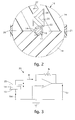
- the electric cable 11 ( figs. 1 and 2 ) comprises a metal conductor 13 having a diameter of about 1.7 mm and wrapped in an insulating sheath 14 of a plastic type, having a diameter of about 2.2 mm.
- the device 10 comprises a support 16 made for example of plastic material, having a tubular shape and consisting of two elements, respectively first 18 and second 19, connected to each other by means of a hinge 20 and able to be reciprocally clamped by means of a snap-in element 21.
- the two elements 18 and 19 define inside a shaped compartment 22, inside which the electric cable 11 is inserted under pressure and thus clamped to the support 16. Moreover, the closure achieved by means of the snap-in element 21 guarantees a good seal which prevents the entrance of liquids or humidity into the compartment 22.
- the device 10 also comprises an armor 25, made of metal or other electrically conducting material and, in the case shown here as an example, a piezoelectric element 26, fixed to a wall 27 of the compartment 22 and to which in turn said armor 25 is fixed.
- the armor 25 is disposed in close proximity with the insulating sheath 14 and is distanced from it by a few tenths of a millimeter, at least two tenths of a millimeter, for the reasons explained hereafter, and from the metal conductor 13 by an average distance D 0 of about 2 mm. In this way, the armor 25 achieves, together with the metal conductor 13, a coupling of a capacitive type, therefore defining a capacitor, the dielectric of which is represented by the insulating sheath 14 and the air.
- the armor 25 is also mechanically connected to the piezoelectric element 26 so that, when the latter is made to vibrate, the armor 25 vibrates too, varying the distance from the metal conductor 13 and consequently varying the capacity of said capacitor which, as is known, is defined by the geometric characteristics of the capacitor.
- the amplitude of the vibration can be estimated at a value of about a tenth of a millimeter
- the presence of an air interspace of a minimum of two tenths of a millimeter between the armor 25 and the insulating sheath 14 guarantees that, during functioning, there is never any contact between these two elements.
- the device 10 also comprises a command and control unit 30, shown schematically in fig. 1 , which carries out a conditioning and amplification of the signal of detected current I IN , processes it and consequently feeds a second luminous indicator 31 disposed in the trailer.
- a command and control unit 30, shown schematically in fig. 1 which carries out a conditioning and amplification of the signal of detected current I IN , processes it and consequently feeds a second luminous indicator 31 disposed in the trailer.
- the conditioning and amplification are achieved by means of an electronic circuit 33, whose electric diagram is shown in fig. 3 , comprising an operational amplifier, for example LM308AN, in a configuration as a trans-impedance amplifier, that is to say, able to effect the conversion of the detected current I IN into an output tension V U proportional thereto.
- an operational amplifier for example LM308AN
- the detected current I IN is sent to the inverting clamp of the operational amplifier, and between this and the outlet clamp a resistance R F is connected, of a value, for example, equal to about 1 M ⁇ .
- R F resistance
- this configuration is inverting and has a gain equal to the value of R F .
- the command and control unit 30 then processes the output tension V U to command the electric feed to the luminous indicator 31 of the trailer by means of a battery 34.
- the command and control unit 30 also comprises an electric generator 35 ( figs. 4 and 5 ) able to feed the piezoelectric element 26 with a, for example, sinusoidal tension, having an amplitude comprised between about 1 V and 100 V and a frequency comprised between about 10 Hz and about 1000 Hz, to make it vibrate at a desired frequency.
- an electric generator 35 figs. 4 and 5 .
- the piezoelectric element 26 is maintained in constant vibration, so that the armor 25 is able to provide promptly the signal of detected current I IN to the electronic circuit 33.
- the signal of current I IN generated by the armor 25 is correlated to the feed tension V DC on the metal conductor 13. To be more exact, as the amplitude of the feed tension V DC increases, the amplitude of the signal current I IN increases linearly.
- a mechanical amplifier is disposed, in the form of a winged metal element 40 in fig. 4 and a metal foil element 140 in fig. 5 .
- the function of the mechanical amplifier 40, 140 is to amplify the entity of the oscillation generated by excitation of the piezoelectric element 26, so that the armor 25 is subject to an oscillation of greater entity even when there is a much reduced oscillation of the piezoelectric element 26.
- the piezoelectric element 26 is distanced from the conductor cable 13 and from the armor 25, preventing induction phenomena.
- the device 10 needs a preliminary calibration of the command and control unit 30, which is effected at the moment of installation, and which pre-supposes that only two conditions are identified, corresponding to the absence of tension V DC on the conductor 13, and the presence thereof.
- the electric feed plant of the luminous indicators of motor vehicles provides a direct feed tension V DC with two values: 0 V, corresponding to the absence of a signal, and a tension comprised between 6 V and 48 V, normally 12 V for motor vehicles, corresponding to the feed tension of said indicators.
- the invention allows to detect without contact any tension whatsoever, both direct and alternating, that varies inside the calibration range.
- a capacitor is electrically connected which reduces the high-frequency noise and the risk of oscillations of the electronic circuit 33.
Landscapes
- Physics & Mathematics (AREA)
- General Physics & Mathematics (AREA)
- Force Measurement Appropriate To Specific Purposes (AREA)
Claims (10)
- Vorrichtung zur berührungslosen Erkennung der Spannung (VDC) in einem elektrischen Kabel (11), insbesondere im Automobilbereich, wobei das elektrische Kabel (11) mindestens einen Leiter (13) umfasst, der von einem isolierendem Mantel (14) umhüllt ist, wobei die Vorrichtung zumindest eine Messelektrode (25) umfasst, die in der Nähe des Leiters (13) angeordnet ist und zu Mitteln (26) gehört, die eine Schwingung anregen können, um daraufhin eine mit der in dem elektrischen Kabel (11) vorliegenden Spannung (VDC) in Zusammenhang stehende Änderung der Ladung zu erzeugen, wobei die Messelektrode (25) mit einem gewissen Abstand zu dem isolierenden Mantel (14) angeordnet ist und mit dem Leiter (13) einen Kondensator bildet, dessen Elektroden die Messelektrode (25) und der Leiter (13) selbst darstellen und dessen Dielektrikum sowohl der isolierende Mantel (14) als auch der Luftspalt, der die Messelektrode (25) von dem isolierendem Mantel (14) trennt, darstellen, wobei der Luftspalt zumindest zwei Zehntel eines Millimeters beträgt, damit sichergestellt Wird, dass bei Betrieb und Schwingung der Messelektrode (25) nie ein Kontakt zwischen dem Mantel (14) und der Messelektrode (25) stattfindet, wobei die Vorrichtung ferner zumindest ein Halteelement (16) mit einem geformten Innenraum (22) umfasst, in dem zumindest die Messelektrode (25) und die Mittel (26), die eine Schwingung anregen können, angeordnet sind, wobei das Halteelement (16) ferner zumindest einen Längskanal aufweist, in den das elektrische Kabel (11) eingeführt und dort fixiert wird.
- Vorrichtung nach Anspruch 1, dadurch gekennzeichnet, dass die Messelektrode (25) zumindest teilweise das elektrische Kabel (11) umschließt.
- Vorrichtung nach Anspruch 1, dadurch gekennzeichnet, dass die Änderung der Ladung über die Zeit einen erkannten Strom (IIN) definiert, der im Wesentlichen proportional zu der Spannung (VDC) in dem elektrischen Kabel (11) ist.
- Vorrichtung nach Anspruch 1, dadurch gekennzeichnet, dass die Mittel, die eine Schwingung anregen können, zumindest ein piezoelektrisches Element (26) umfassen.
- Vorrichtung nach Anspruch 4, dadurch gekennzeichnet, dass das piezoelektrische Element (26) mit Wechselstrom versorgt wird.
- Vorrichtung nach Anspruch 4, dadurch gekennzeichnet, dass sich zwischen dem piezoelektrischen Element (26) und der Messelektrode (25) zumindest ein schwingungsverstärkendes Element (40, 140) befindet.
- Vorrichtung nach Anspruch 6, dadurch gekennzeichnet, dass das schwingungsverstärkende Element in Form eines mit Flügeln versehenen Metallelements (40) vorliegt.
- Vorrichtung nach Anspruch 6, dadurch gekennzeichnet, dass das schwingungsverstärkende Element in Form eines Metallfolienelements (140) vorliegt.
- Vorrichtung nach Anspruch 1, dadurch gekennzeichnet, dass das Halteelement (16) zwei Schalen (18, 19) umfasst, die durch ein Scharnierelement (20) miteinander verbunden und auf der dem Scharnier (20) gegenüberliegenden Seite von einem Einrastelement (21) geklemmt werden.
- Vorrichtung nach Anspruch 3, dadurch gekennzeichnet, dass sie ferner eine Befehls- und Steuereinheit (30) umfasst, die den erkannten Strom (IIN) aufbereiten und verstärken und für die Zuführung zu Signalisierungsmitteln (31) verarbeiten kann.
Applications Claiming Priority (2)
| Application Number | Priority Date | Filing Date | Title |
|---|---|---|---|
| ITUD20050099 ITUD20050099A1 (it) | 2005-06-14 | 2005-06-14 | Dispositivo per rilevare senza contatto la tensione in un cavo elettrico |
| PCT/EP2006/063131 WO2006134097A1 (en) | 2005-06-14 | 2006-06-13 | Device to detect without contact the tension in an electric cable |
Publications (2)
| Publication Number | Publication Date |
|---|---|
| EP1894024A1 EP1894024A1 (de) | 2008-03-05 |
| EP1894024B1 true EP1894024B1 (de) | 2016-11-23 |
Family
ID=35429555
Family Applications (1)
| Application Number | Title | Priority Date | Filing Date |
|---|---|---|---|
| EP06763660.5A Not-in-force EP1894024B1 (de) | 2005-06-14 | 2006-06-13 | Einrichtung zum kontaklosen detektieren der spannung in einem elektrischen kabel |
Country Status (3)
| Country | Link |
|---|---|
| EP (1) | EP1894024B1 (de) |
| IT (1) | ITUD20050099A1 (de) |
| WO (1) | WO2006134097A1 (de) |
Citations (1)
| Publication number | Priority date | Publication date | Assignee | Title |
|---|---|---|---|---|
| US4928057A (en) * | 1986-10-28 | 1990-05-22 | Williams Bruce T | High speed D.C. non-contacting electrostatic voltage follower |
Family Cites Families (2)
| Publication number | Priority date | Publication date | Assignee | Title |
|---|---|---|---|---|
| CN1200810A (zh) | 1995-09-04 | 1998-12-02 | 西门子公司 | 用于中/高电压设备具有表面波设备的电压表 |
| DE10021714A1 (de) | 1999-08-20 | 2001-02-22 | Siemens Ag | Verfahren und Vorrichtung zur kapazitiven Messung eines elektrischen Leiterpotentials über eine mechanische Schwingung der Isolierung |
-
2005
- 2005-06-14 IT ITUD20050099 patent/ITUD20050099A1/it unknown
-
2006
- 2006-06-13 WO PCT/EP2006/063131 patent/WO2006134097A1/en not_active Ceased
- 2006-06-13 EP EP06763660.5A patent/EP1894024B1/de not_active Not-in-force
Patent Citations (1)
| Publication number | Priority date | Publication date | Assignee | Title |
|---|---|---|---|---|
| US4928057A (en) * | 1986-10-28 | 1990-05-22 | Williams Bruce T | High speed D.C. non-contacting electrostatic voltage follower |
Also Published As
| Publication number | Publication date |
|---|---|
| ITUD20050099A1 (it) | 2006-12-15 |
| WO2006134097A1 (en) | 2006-12-21 |
| EP1894024A1 (de) | 2008-03-05 |
Similar Documents
| Publication | Publication Date | Title |
|---|---|---|
| US6972575B2 (en) | Capacitive proximity sensor | |
| US6664708B2 (en) | Method and device for non-contact detection of external electric or magnetic fields | |
| DK168748B1 (da) | Bilantenne med højfrekvenspickup | |
| KR0151568B1 (ko) | 초음파수신장치 및 장해물검지장치 | |
| US5682136A (en) | Electromagnetic detection system for parking operation | |
| CN101636908A (zh) | 借助电近场吸收探测身体部位的装置 | |
| JP5506390B2 (ja) | 近傍電界の吸収による体の一部の検出のための装置 | |
| CA2167260A1 (en) | Partial-discharge measuring device | |
| JP6829852B2 (ja) | 車両内通信装置及び方法 | |
| CN102246417B (zh) | 用于检测检测区域中的物体的传感器装置 | |
| WO2006134097A1 (en) | Device to detect without contact the tension in an electric cable | |
| JP2007232496A (ja) | Gis用部分放電検出センサおよびこれを使用する絶縁異常監視システム | |
| CN102934360A (zh) | 电容性传感器系统 | |
| US4040044A (en) | Dual line electret transducer | |
| US11719737B2 (en) | Sensing arrangement | |
| US20120019264A1 (en) | Multi purpose capacitive sensor | |
| US8049633B2 (en) | Electric field whistle | |
| JP3150765B2 (ja) | 送電線近接監視システム | |
| JP3199726B2 (ja) | 部分放電検出装置 | |
| US6734698B2 (en) | Radio frequency oscillation detector | |
| KR101594756B1 (ko) | 부분방전 측정 장치 및 그 방법 | |
| JP2978718B2 (ja) | 電力ケーブルの普通接続部 | |
| JP3626513B2 (ja) | 反射波監視装置 | |
| JP7852368B2 (ja) | 物体検出装置および物体検出システム | |
| JP2645939B2 (ja) | タイヤ空気圧警報装置 |
Legal Events
| Date | Code | Title | Description |
|---|---|---|---|
| PUAI | Public reference made under article 153(3) epc to a published international application that has entered the european phase |
Free format text: ORIGINAL CODE: 0009012 |
|
| 17P | Request for examination filed |
Effective date: 20080110 |
|
| AK | Designated contracting states |
Kind code of ref document: A1 Designated state(s): AT BE BG CH CY CZ DE DK EE ES FI FR GB GR HU IE IS IT LI LT LU LV MC NL PL PT RO SE SI SK TR |
|
| DAX | Request for extension of the european patent (deleted) | ||
| DAX | Request for extension of the european patent (deleted) | ||
| 17Q | First examination report despatched |
Effective date: 20130610 |
|
| GRAP | Despatch of communication of intention to grant a patent |
Free format text: ORIGINAL CODE: EPIDOSNIGR1 |
|
| RIC1 | Information provided on ipc code assigned before grant |
Ipc: G01R 15/16 20060101AFI20160411BHEP Ipc: G01R 15/26 20060101ALI20160411BHEP |
|
| INTG | Intention to grant announced |
Effective date: 20160429 |
|
| GRAS | Grant fee paid |
Free format text: ORIGINAL CODE: EPIDOSNIGR3 |
|
| GRAA | (expected) grant |
Free format text: ORIGINAL CODE: 0009210 |
|
| RAP1 | Party data changed (applicant data changed or rights of an application transferred) |
Owner name: LITTELFUSE COMMERCIAL VEHICLE PRODUCTS, ITALY S.R. |
|
| AK | Designated contracting states |
Kind code of ref document: B1 Designated state(s): AT BE BG CH CY CZ DE DK EE ES FI FR GB GR HU IE IS IT LI LT LU LV MC NL PL PT RO SE SI SK TR |
|
| REG | Reference to a national code |
Ref country code: GB Ref legal event code: FG4D |
|
| REG | Reference to a national code |
Ref country code: CH Ref legal event code: EP |
|
| REG | Reference to a national code |
Ref country code: IE Ref legal event code: FG4D |
|
| REG | Reference to a national code |
Ref country code: AT Ref legal event code: REF Ref document number: 848383 Country of ref document: AT Kind code of ref document: T Effective date: 20161215 |
|
| REG | Reference to a national code |
Ref country code: DE Ref legal event code: R096 Ref document number: 602006051020 Country of ref document: DE |
|
| PG25 | Lapsed in a contracting state [announced via postgrant information from national office to epo] |
Ref country code: LV Free format text: LAPSE BECAUSE OF FAILURE TO SUBMIT A TRANSLATION OF THE DESCRIPTION OR TO PAY THE FEE WITHIN THE PRESCRIBED TIME-LIMIT Effective date: 20161123 |
|
| REG | Reference to a national code |
Ref country code: LT Ref legal event code: MG4D |
|
| REG | Reference to a national code |
Ref country code: NL Ref legal event code: MP Effective date: 20161123 |
|
| REG | Reference to a national code |
Ref country code: AT Ref legal event code: MK05 Ref document number: 848383 Country of ref document: AT Kind code of ref document: T Effective date: 20161123 |
|
| PG25 | Lapsed in a contracting state [announced via postgrant information from national office to epo] |
Ref country code: GR Free format text: LAPSE BECAUSE OF FAILURE TO SUBMIT A TRANSLATION OF THE DESCRIPTION OR TO PAY THE FEE WITHIN THE PRESCRIBED TIME-LIMIT Effective date: 20170224 Ref country code: SE Free format text: LAPSE BECAUSE OF FAILURE TO SUBMIT A TRANSLATION OF THE DESCRIPTION OR TO PAY THE FEE WITHIN THE PRESCRIBED TIME-LIMIT Effective date: 20161123 Ref country code: NL Free format text: LAPSE BECAUSE OF FAILURE TO SUBMIT A TRANSLATION OF THE DESCRIPTION OR TO PAY THE FEE WITHIN THE PRESCRIBED TIME-LIMIT Effective date: 20161123 Ref country code: LT Free format text: LAPSE BECAUSE OF FAILURE TO SUBMIT A TRANSLATION OF THE DESCRIPTION OR TO PAY THE FEE WITHIN THE PRESCRIBED TIME-LIMIT Effective date: 20161123 |
|
| PG25 | Lapsed in a contracting state [announced via postgrant information from national office to epo] |
Ref country code: AT Free format text: LAPSE BECAUSE OF FAILURE TO SUBMIT A TRANSLATION OF THE DESCRIPTION OR TO PAY THE FEE WITHIN THE PRESCRIBED TIME-LIMIT Effective date: 20161123 Ref country code: PT Free format text: LAPSE BECAUSE OF FAILURE TO SUBMIT A TRANSLATION OF THE DESCRIPTION OR TO PAY THE FEE WITHIN THE PRESCRIBED TIME-LIMIT Effective date: 20170323 Ref country code: ES Free format text: LAPSE BECAUSE OF FAILURE TO SUBMIT A TRANSLATION OF THE DESCRIPTION OR TO PAY THE FEE WITHIN THE PRESCRIBED TIME-LIMIT Effective date: 20161123 Ref country code: FI Free format text: LAPSE BECAUSE OF FAILURE TO SUBMIT A TRANSLATION OF THE DESCRIPTION OR TO PAY THE FEE WITHIN THE PRESCRIBED TIME-LIMIT Effective date: 20161123 Ref country code: PL Free format text: LAPSE BECAUSE OF FAILURE TO SUBMIT A TRANSLATION OF THE DESCRIPTION OR TO PAY THE FEE WITHIN THE PRESCRIBED TIME-LIMIT Effective date: 20161123 |
|
| PG25 | Lapsed in a contracting state [announced via postgrant information from national office to epo] |
Ref country code: RO Free format text: LAPSE BECAUSE OF FAILURE TO SUBMIT A TRANSLATION OF THE DESCRIPTION OR TO PAY THE FEE WITHIN THE PRESCRIBED TIME-LIMIT Effective date: 20161123 Ref country code: CZ Free format text: LAPSE BECAUSE OF FAILURE TO SUBMIT A TRANSLATION OF THE DESCRIPTION OR TO PAY THE FEE WITHIN THE PRESCRIBED TIME-LIMIT Effective date: 20161123 Ref country code: SK Free format text: LAPSE BECAUSE OF FAILURE TO SUBMIT A TRANSLATION OF THE DESCRIPTION OR TO PAY THE FEE WITHIN THE PRESCRIBED TIME-LIMIT Effective date: 20161123 Ref country code: DK Free format text: LAPSE BECAUSE OF FAILURE TO SUBMIT A TRANSLATION OF THE DESCRIPTION OR TO PAY THE FEE WITHIN THE PRESCRIBED TIME-LIMIT Effective date: 20161123 Ref country code: EE Free format text: LAPSE BECAUSE OF FAILURE TO SUBMIT A TRANSLATION OF THE DESCRIPTION OR TO PAY THE FEE WITHIN THE PRESCRIBED TIME-LIMIT Effective date: 20161123 |
|
| REG | Reference to a national code |
Ref country code: DE Ref legal event code: R097 Ref document number: 602006051020 Country of ref document: DE |
|
| PG25 | Lapsed in a contracting state [announced via postgrant information from national office to epo] |
Ref country code: BE Free format text: LAPSE BECAUSE OF FAILURE TO SUBMIT A TRANSLATION OF THE DESCRIPTION OR TO PAY THE FEE WITHIN THE PRESCRIBED TIME-LIMIT Effective date: 20161123 Ref country code: BG Free format text: LAPSE BECAUSE OF FAILURE TO SUBMIT A TRANSLATION OF THE DESCRIPTION OR TO PAY THE FEE WITHIN THE PRESCRIBED TIME-LIMIT Effective date: 20170223 |
|
| PLBE | No opposition filed within time limit |
Free format text: ORIGINAL CODE: 0009261 |
|
| STAA | Information on the status of an ep patent application or granted ep patent |
Free format text: STATUS: NO OPPOSITION FILED WITHIN TIME LIMIT |
|
| 26N | No opposition filed |
Effective date: 20170824 |
|
| PG25 | Lapsed in a contracting state [announced via postgrant information from national office to epo] |
Ref country code: SI Free format text: LAPSE BECAUSE OF FAILURE TO SUBMIT A TRANSLATION OF THE DESCRIPTION OR TO PAY THE FEE WITHIN THE PRESCRIBED TIME-LIMIT Effective date: 20161123 |
|
| PG25 | Lapsed in a contracting state [announced via postgrant information from national office to epo] |
Ref country code: MC Free format text: LAPSE BECAUSE OF FAILURE TO SUBMIT A TRANSLATION OF THE DESCRIPTION OR TO PAY THE FEE WITHIN THE PRESCRIBED TIME-LIMIT Effective date: 20161123 |
|
| REG | Reference to a national code |
Ref country code: CH Ref legal event code: PL |
|
| GBPC | Gb: european patent ceased through non-payment of renewal fee |
Effective date: 20170613 |
|
| REG | Reference to a national code |
Ref country code: IE Ref legal event code: MM4A |
|
| REG | Reference to a national code |
Ref country code: FR Ref legal event code: ST Effective date: 20180228 |
|
| PG25 | Lapsed in a contracting state [announced via postgrant information from national office to epo] |
Ref country code: LI Free format text: LAPSE BECAUSE OF NON-PAYMENT OF DUE FEES Effective date: 20170630 Ref country code: IE Free format text: LAPSE BECAUSE OF NON-PAYMENT OF DUE FEES Effective date: 20170613 Ref country code: GB Free format text: LAPSE BECAUSE OF NON-PAYMENT OF DUE FEES Effective date: 20170613 Ref country code: CH Free format text: LAPSE BECAUSE OF NON-PAYMENT OF DUE FEES Effective date: 20170630 Ref country code: LU Free format text: LAPSE BECAUSE OF NON-PAYMENT OF DUE FEES Effective date: 20170613 |
|
| PG25 | Lapsed in a contracting state [announced via postgrant information from national office to epo] |
Ref country code: FR Free format text: LAPSE BECAUSE OF NON-PAYMENT OF DUE FEES Effective date: 20170630 |
|
| PGFP | Annual fee paid to national office [announced via postgrant information from national office to epo] |
Ref country code: DE Payment date: 20180627 Year of fee payment: 13 Ref country code: IT Payment date: 20180621 Year of fee payment: 13 |
|
| PG25 | Lapsed in a contracting state [announced via postgrant information from national office to epo] |
Ref country code: HU Free format text: LAPSE BECAUSE OF FAILURE TO SUBMIT A TRANSLATION OF THE DESCRIPTION OR TO PAY THE FEE WITHIN THE PRESCRIBED TIME-LIMIT; INVALID AB INITIO Effective date: 20060613 |
|
| PG25 | Lapsed in a contracting state [announced via postgrant information from national office to epo] |
Ref country code: CY Free format text: LAPSE BECAUSE OF NON-PAYMENT OF DUE FEES Effective date: 20161123 |
|
| REG | Reference to a national code |
Ref country code: DE Ref legal event code: R119 Ref document number: 602006051020 Country of ref document: DE |
|
| PG25 | Lapsed in a contracting state [announced via postgrant information from national office to epo] |
Ref country code: TR Free format text: LAPSE BECAUSE OF FAILURE TO SUBMIT A TRANSLATION OF THE DESCRIPTION OR TO PAY THE FEE WITHIN THE PRESCRIBED TIME-LIMIT Effective date: 20161123 |
|
| PG25 | Lapsed in a contracting state [announced via postgrant information from national office to epo] |
Ref country code: DE Free format text: LAPSE BECAUSE OF NON-PAYMENT OF DUE FEES Effective date: 20200101 Ref country code: IT Free format text: LAPSE BECAUSE OF NON-PAYMENT OF DUE FEES Effective date: 20190613 |
|
| PG25 | Lapsed in a contracting state [announced via postgrant information from national office to epo] |
Ref country code: IS Free format text: LAPSE BECAUSE OF FAILURE TO SUBMIT A TRANSLATION OF THE DESCRIPTION OR TO PAY THE FEE WITHIN THE PRESCRIBED TIME-LIMIT Effective date: 20170323 |
|
| P01 | Opt-out of the competence of the unified patent court (upc) registered |
Effective date: 20230607 |