EP1893439B1 - A child vehicle seating system - Google Patents
A child vehicle seating system Download PDFInfo
- Publication number
- EP1893439B1 EP1893439B1 EP06744111A EP06744111A EP1893439B1 EP 1893439 B1 EP1893439 B1 EP 1893439B1 EP 06744111 A EP06744111 A EP 06744111A EP 06744111 A EP06744111 A EP 06744111A EP 1893439 B1 EP1893439 B1 EP 1893439B1
- Authority
- EP
- European Patent Office
- Prior art keywords
- seating
- seating system
- child
- child vehicle
- channel
- Prior art date
- Legal status (The legal status is an assumption and is not a legal conclusion. Google has not performed a legal analysis and makes no representation as to the accuracy of the status listed.)
- Not-in-force
Links
Images


Classifications
-
- B—PERFORMING OPERATIONS; TRANSPORTING
- B62—LAND VEHICLES FOR TRAVELLING OTHERWISE THAN ON RAILS
- B62B—HAND-PROPELLED VEHICLES, e.g. HAND CARTS OR PERAMBULATORS; SLEDGES
- B62B9/00—Accessories or details specially adapted for children's carriages or perambulators
- B62B9/10—Perambulator bodies; Equipment therefor
-
- B—PERFORMING OPERATIONS; TRANSPORTING
- B60—VEHICLES IN GENERAL
- B60N—SEATS SPECIALLY ADAPTED FOR VEHICLES; VEHICLE PASSENGER ACCOMMODATION NOT OTHERWISE PROVIDED FOR
- B60N2/00—Seats specially adapted for vehicles; Arrangement or mounting of seats in vehicles
- B60N2/24—Seats specially adapted for vehicles; Arrangement or mounting of seats in vehicles for particular purposes or particular vehicles
- B60N2/26—Seats specially adapted for vehicles; Arrangement or mounting of seats in vehicles for particular purposes or particular vehicles for children
- B60N2/28—Seats readily mountable on, and dismountable from, existing seats or other parts of the vehicle
- B60N2/2821—Seats readily mountable on, and dismountable from, existing seats or other parts of the vehicle having a seat and a base part
-
- B—PERFORMING OPERATIONS; TRANSPORTING
- B60—VEHICLES IN GENERAL
- B60N—SEATS SPECIALLY ADAPTED FOR VEHICLES; VEHICLE PASSENGER ACCOMMODATION NOT OTHERWISE PROVIDED FOR
- B60N2/00—Seats specially adapted for vehicles; Arrangement or mounting of seats in vehicles
- B60N2/24—Seats specially adapted for vehicles; Arrangement or mounting of seats in vehicles for particular purposes or particular vehicles
- B60N2/26—Seats specially adapted for vehicles; Arrangement or mounting of seats in vehicles for particular purposes or particular vehicles for children
- B60N2/28—Seats readily mountable on, and dismountable from, existing seats or other parts of the vehicle
- B60N2/2851—Seats readily mountable on, and dismountable from, existing seats or other parts of the vehicle provided with head-rests
-
- B—PERFORMING OPERATIONS; TRANSPORTING
- B60—VEHICLES IN GENERAL
- B60N—SEATS SPECIALLY ADAPTED FOR VEHICLES; VEHICLE PASSENGER ACCOMMODATION NOT OTHERWISE PROVIDED FOR
- B60N2/00—Seats specially adapted for vehicles; Arrangement or mounting of seats in vehicles
- B60N2/24—Seats specially adapted for vehicles; Arrangement or mounting of seats in vehicles for particular purposes or particular vehicles
- B60N2/26—Seats specially adapted for vehicles; Arrangement or mounting of seats in vehicles for particular purposes or particular vehicles for children
- B60N2/28—Seats readily mountable on, and dismountable from, existing seats or other parts of the vehicle
- B60N2/2854—Children's cots; Hammocks
-
- B—PERFORMING OPERATIONS; TRANSPORTING
- B60—VEHICLES IN GENERAL
- B60N—SEATS SPECIALLY ADAPTED FOR VEHICLES; VEHICLE PASSENGER ACCOMMODATION NOT OTHERWISE PROVIDED FOR
- B60N2/00—Seats specially adapted for vehicles; Arrangement or mounting of seats in vehicles
- B60N2/24—Seats specially adapted for vehicles; Arrangement or mounting of seats in vehicles for particular purposes or particular vehicles
- B60N2/26—Seats specially adapted for vehicles; Arrangement or mounting of seats in vehicles for particular purposes or particular vehicles for children
- B60N2/28—Seats readily mountable on, and dismountable from, existing seats or other parts of the vehicle
- B60N2/2872—Seats readily mountable on, and dismountable from, existing seats or other parts of the vehicle provided with side rests
-
- B—PERFORMING OPERATIONS; TRANSPORTING
- B60—VEHICLES IN GENERAL
- B60N—SEATS SPECIALLY ADAPTED FOR VEHICLES; VEHICLE PASSENGER ACCOMMODATION NOT OTHERWISE PROVIDED FOR
- B60N2/00—Seats specially adapted for vehicles; Arrangement or mounting of seats in vehicles
- B60N2/24—Seats specially adapted for vehicles; Arrangement or mounting of seats in vehicles for particular purposes or particular vehicles
- B60N2/26—Seats specially adapted for vehicles; Arrangement or mounting of seats in vehicles for particular purposes or particular vehicles for children
- B60N2/28—Seats readily mountable on, and dismountable from, existing seats or other parts of the vehicle
- B60N2/2881—Upholstery, padded or cushioned members therefor
-
- B—PERFORMING OPERATIONS; TRANSPORTING
- B60—VEHICLES IN GENERAL
- B60N—SEATS SPECIALLY ADAPTED FOR VEHICLES; VEHICLE PASSENGER ACCOMMODATION NOT OTHERWISE PROVIDED FOR
- B60N2/00—Seats specially adapted for vehicles; Arrangement or mounting of seats in vehicles
- B60N2/70—Upholstery springs ; Upholstery
- B60N2/7011—Upholstery springs ; Upholstery of substantially two-dimensional shape, e.g. hammock-like, plastic shells, fabrics
-
- B—PERFORMING OPERATIONS; TRANSPORTING
- B62—LAND VEHICLES FOR TRAVELLING OTHERWISE THAN ON RAILS
- B62B—HAND-PROPELLED VEHICLES, e.g. HAND CARTS OR PERAMBULATORS; SLEDGES
- B62B7/00—Carriages for children; Perambulators, e.g. dolls' perambulators
- B62B7/04—Carriages for children; Perambulators, e.g. dolls' perambulators having more than one wheel axis; Steering devices therefor
- B62B7/14—Carriages for children; Perambulators, e.g. dolls' perambulators having more than one wheel axis; Steering devices therefor with detachable or rotatably-mounted body
-
- B—PERFORMING OPERATIONS; TRANSPORTING
- B62—LAND VEHICLES FOR TRAVELLING OTHERWISE THAN ON RAILS
- B62B—HAND-PROPELLED VEHICLES, e.g. HAND CARTS OR PERAMBULATORS; SLEDGES
- B62B7/00—Carriages for children; Perambulators, e.g. dolls' perambulators
- B62B7/004—Carriages supporting a hammock-style seat
-
- B—PERFORMING OPERATIONS; TRANSPORTING
- B62—LAND VEHICLES FOR TRAVELLING OTHERWISE THAN ON RAILS
- B62B—HAND-PROPELLED VEHICLES, e.g. HAND CARTS OR PERAMBULATORS; SLEDGES
- B62B7/00—Carriages for children; Perambulators, e.g. dolls' perambulators
- B62B7/04—Carriages for children; Perambulators, e.g. dolls' perambulators having more than one wheel axis; Steering devices therefor
- B62B7/14—Carriages for children; Perambulators, e.g. dolls' perambulators having more than one wheel axis; Steering devices therefor with detachable or rotatably-mounted body
- B62B7/145—Carriages for children; Perambulators, e.g. dolls' perambulators having more than one wheel axis; Steering devices therefor with detachable or rotatably-mounted body the body being a rigid seat, e.g. a shell
-
- B—PERFORMING OPERATIONS; TRANSPORTING
- B62—LAND VEHICLES FOR TRAVELLING OTHERWISE THAN ON RAILS
- B62B—HAND-PROPELLED VEHICLES, e.g. HAND CARTS OR PERAMBULATORS; SLEDGES
- B62B9/00—Accessories or details specially adapted for children's carriages or perambulators
- B62B9/20—Handle bars; Handles
- B62B9/206—Handle bars; Handles with two separate bars, i.e. not interconnected
Definitions
- the present invention relates to a child vehicle seating system for fitment on a vehicle seat to support and restrain a child.
- a child vehicle seating system according to the preamble of claim 1 is shown by DE 203 08 464 U1 .
- Such seats/carriers are secured in position on a vehicle seat by means of a conventional seat belt (i.e. a seat belt having three anchor points so as to define a shoulder strap and a waist strap) passing through fitment points provided on the rear surface of the support component.
- a conventional seat belt i.e. a seat belt having three anchor points so as to define a shoulder strap and a waist strap
- fitment points provided on the rear surface of the support component.
- the bulk and weight of the seats/carriers can cause problems during this fitment process since they are difficult to manoeuvre and users find it difficult to see behind them in order to correctly locate the seat belt. In a recent survey, over 70% of seats/carriers were found to be fitted incorrectly.
- a relatively solid support component in combination with a padded cover also means that the seats/carriers are poorly ventilated and does not therefore assist in ensuring that a child seated therein does not overheat. Furthermore, the padded cover is often cumbersome and can prove difficult to remove, wash and replace, thereby deterring the user from trying.
- a child vehicle seating system for fitment on a vehicle seat to support and restrain a child, comprising at least one seating component, the or each seating component including a closed frame over which a flexible membrane is stretched to define a support surface.
- At least one seating component including a support surface defined by a flexible membrane stretched over a closed frame means that a solid support member is not required. This enables the provision of a seating system that is considerably lighter and less bulky than hereto known seats/carriers.
- the child vehicle seating system includes at least first and second separate seating components interconnected to define a seat and a back, each seating component including a closed frame over which a flexible membrane is stretched to define a support surface.
- the child vehicle seating system may also include a third seating component having a closed frame over which a flexible membrane is stretched to define a support surface, the third seating component being connected to the second seating component to define a head rest.
- the or each of the closed frames is preferably shaped such that the flexible membrane stretched over the frame forms a contoured support surface.
- the provision of a flexible membrane tensioned over a shaped frame enables the seating components to be shaped in order to curve around a child when the child is seating in the seating system and thereby improve the support provided by the seating components.
- the seating components it also enables the seating components to be shaped to minimize the amount of contact between a child supported by the seating system and solid components. Consequently, the overall comfort of the seating system can be improved and the likelihood of pressure injuries, such as bruises and grazes, which may otherwise occur through contact with solid components, particularly in the event of a vehicular accident, can be reduced.
- references herein to a closed frame are intended to refer to a continuous frame bounding a hollow interior, which may include two or more opposed frame elements connected end to end to form a closed frame.
- the flexible membrane is formed from a porous, breathable, fabric. This ensures that the seat is ventilated and thereby reduces the risk of a child supported by the seating system overheating as a result of high ambient temperatures.
- the porous, breathable, fabric is a mesh fabric that allows a user to see through the seating components. This can be particularly advantageous during the fitment process of the seating system on a vehicle seat since it allows the user to see behind the seating components.
- first and second seating components are interconnected by means of a connecting arrangement including a floor-engaging support member such that the seating system is self-supporting.
- references herein to a vehicle seat belt are intended to refer to a conventional vehicle seat belt having three anchor points so as to define a shoulder strap and a waist strap.
- the seating system 10 includes first and second seating components 12,14 interconnected to define a seat and a back, each seating component 12,14 including a closed frame 16 over which a flexible membrane 18 is stretched to define a support surface.
- the seating system 10 also includes a third seating component 20 having a closed frame 16 over which a flexible membrane 18 is stretched to define a support surface, the third seating component 20 being connected to the second seating component 14 to define a head rest.
- the closed frame 16 of each of the seating components 12,14,20 is preferably shaped such that the flexible membrane 18 stretched over the frame 16 forms a contoured support surface.
- the frames 16 of the seating components 12,14,20 are shaped to curve around a child seated in the seating system 10 to support the child and resist sideways movement of the child relative to the seating components 12,14,20.
- This is exemplified in Figures 3 and 4 , which show the seating component 12 forming the seat of the seating system 10 ( Figure 3 ) and the corresponding frame 16 ( Figure 4 ).
- the frames 16 of the seating components 12,14,20 are also shaped so that the support provided by each of the seating components 12,14,20 is provided entirely by the contoured support surface defined by the flexible membrane 18 stretched over the associated frame 16.
- This arrangement minimizes the amount of contact between a child seated in the seating system 10 and solid components (e.g. the frames 16). It therefore minimizes the risk of discomfort or injuries that may otherwise result from contact between a child seated in the seating system 10 and solid components in the seating system 10.
- the flexible membrane 18 stretched over the frame 16 of each of the seating components 12,14,20 is preferably a porous, breathable fabric to ventilate the seating components 12,14,20, and thereby minimize the risk of a child seated in the seating system 10 from overheating in high ambient temperatures.
- the flexible membrane 18 is a porous breathable fabric in the form of a mesh fabric.
- the first and second components 12,14 of the seating system 10 are preferably connected by means of a connecting arrangement, which includes a floor engaging support 22.
- the floor-engaging support 22 preferably assists in maintaining the seating system 10 in an upright position when placed on a flat surface, such as the floor.
- the connecting arrangement includes a support frame 24 interconnecting the seating components 12,14,20.
- the support frame 24 is a curved, tubular structure connected to the first seating component 12 forming the seat, by means of the floor engaging support 22, and extending generally upwards, behind the second seating component 14 forming the back, to the third seating component 20 forming the head rest.
- the connecting arrangement also preferably includes first and second connector members 30,32 extending between the second seating component 14 and the support frame 24 to mount the second seating component 14 on the support frame 24 for sliding movement along the length of the support frame 24.
- the first connector member 30 is fixed at one end towards the bottom of the second seating component 14 and is slidably mounted at its other end on the support frame 24.
- the second connector member 32 is fixed at one end towards the top of the second seating component 14 and is slidably mounted at its other end on the support frame 24.
- Sliding engagement between the connector members 30,32 and the support frame 24 provides means for adjusting the position of the second seating component 14 relative to the first seating component 12, as exemplified by the relative positions of the seating components 12,14 shown in Figures 5 and 6 .
- the second seating component 14 is adjustable through a range of predetermined positions relative to the first seating component 12 to accommodate children of different heights in the seating system 10. This helps to ensure that the correct ergonomic seating position for a child of a given height is provided.
- a scale 34 may be marked on the support frame 24 identifying positions of the second connector member 32 on the support frame 24 which correspond to positions of the second seating component 14 relative to the first seating component required to accommodate children of different heights.
- a window 36 having a marker 38 is provided in the second connector member 32 through which the scale 34 may be viewed, as shown in Figures 7, 8 , 9a and 9b .
- Such an arrangement allows a user to slide the second seating component 14 along the support frame 24 until the height of the child intending to sit in the seating system 10 is aligned with the marker 38 shown in the window 36, as shown in Figures 10a and 10b .
- the position of the second seating component 14 relative to the first seating component 12 can be fixed in position on the support frame, preferably by means of a locking system 40, as shown in Figures 10a - 10d .
- This enables the position of the second seating component 14 relative to the first seating component 12 to be adjusted quickly and accurately for children of different heights without having to adopt a trial and error approach.
- the locking system 40 includes a plurality of equidistantly spaced recesses 42 formed along opposite edges of the support frame 24. Teeth 44 provided on the second connector component 32, on opposite sides of the support frame 24 (only one side being shown), are engageable within the recesses 42 to lock the second connector 32 in position, relative to the support frame 24, and prevent sliding movement of the second connector 32 on the support frame 24, as shown in Figure 10a .
- the teeth 44 are preferably mounted by means of pivot pins 46 that allow pivotal movement of the teeth 44 to move an engagement portion 48 of each tooth 44 into and out of engagement with a respective recess 42.
- Each tooth 44 also preferably includes a cam portion (not shown) received within a release member 50 slidably mounted on the second connector component 32 such that on sliding movement of the release member 50 towards the support frame 24 the release member 50 engages the cam portion of each tooth 44 causing pivotal movement of the tooth 44 to move the engagement portion 48 of the tooth 44 out of engagement with the respective notch 42, as shown in Figure 10b .
- a cam portion (not shown) received within a release member 50 slidably mounted on the second connector component 32 such that on sliding movement of the release member 50 towards the support frame 24 the release member 50 engages the cam portion of each tooth 44 causing pivotal movement of the tooth 44 to move the engagement portion 48 of the tooth 44 out of engagement with the respective notch 42, as shown in Figure 10b .
- the second connector member 32 When the teeth 44 on each side of the support frame 24 are disengaged, the second connector member 32 is free to slide along the support frame 24, as shown in Figure 10c , and thereby allow adjustment of the second seating component 14 relative to the first seating component 12.
- engagement between the release member 50 and the cam portion of each tooth 44 preferably causes pivotal movement of the tooth 44 to move the engagement portion 48 of the tooth 44 into engagement with an adjacent recess 42, as shown in Figure 10d .
- the release member 50 and the teeth 44 are resiliently biased such that the release member 50 automatically moves away from the support frame 24 when released and. on movement of the release member 50 away from the support frame 24 and out of engagement with the cam portion of each tooth 44, a resilient biasing member causes pivotal movement of the tooth 44 to move the engagement portion 48 into engagement with a recess 42.
- This allows the provision of resiliently biased, depressible buttons on opposite sides of the support frame 24 to facilitate adjustment of the second seating component 14 relative to the first seating component 12.
- the connecting arrangement also includes a third connector member 52 mounted on an elongate strut member 54 ( Figure 11 ), which is slidably received within the support frame 24.
- Sliding movement of the strut member 54 into and out of the support frame 24 provides means for adjusting the position of the third seating component 14 relative to the second seating component 14, as exemplified by the relative positions of the seating components 14,20 shown in Figures 5 and 6 .
- the third seating component 20 When the third seating component 20 is positioned in a desired position relative to the second seating component 14, the third seating component can be fixed in position relative to the support frame 24, preferably by means of a locking system.
- the locking system may take a similar form to the locking system 40 associated with the second seating component 14.
- the connecting arrangement defines spaced locators 56,58 to receive and locate a vehicle seat belt 60 when the seat belt 60 is passed across the seating components 12,14,20 during fitment of the seating system 10 on a vehicle seat.
- the provision of the locators 56,58 allows a user to pass the seat belt 60 across the front of the seating components 12,14,20 ( Figure 12a ) so as to align the shoulder strap 62 with an opening between the second and third seating components 14,20 and the waist strap 64 with an opening between the first and second seating components 12,14 ( Figure 12b ).
- the shoulder strap 62 is pulled tightly against a locator 56 defined by the support frame 24 and the second connector member 32 and the waist strap 64 is pulled tightly against a locator 58 defined by the floor-engaging support member 22 ( Figure 12c ).
- the locators 56,58 thereby receive and locate the shoulder and waist straps 62,64 and maintain them in position so that the seating system 10 can be pulled tightly against the vehicle seat.
- This arrangement enables a user to fit the seating system 10 on a vehicle seat without having to locate the seat belt 60 though any connecting members provided on the rear of the seating system. Consequently the user does not need to be able to see and reach behind the seating system 10.
- the seating system 10 includes first and second stabilizer components 66,68 which define spaced contact points at the rear of the seating system 10 to support the seating system 10 when it is fitted on a vehicle seat.
- the first stabilizer component 66 is formed integrally with the floor engaging support 22 to define two laterally extending limbs 22a and 22b defining contact points at their terminal ends, as shown in Figures 7 and 8 .
- the second stabilizer component 68 is mounted at or towards the top of the support frame 24 to define two laterally extending limbs 68a,6857b also defining contact points at their terminal ends, as shown in Figures 7 and 8 .
- a contact pad 68c,68d may be provided on the terminal end of each of the limbs 68a,68b to reduce pressure between the terminal ends and the vehicle seat and thereby reduce the risk of the terminal ends damaging or otherwise marking the vehicle seat when the seating system 10 is fitted thereon and held against the vehicle seat by the seat belt 60.
- the provision of the laterally spaced contact points supports the seating system 10 when fitted on a vehicle seat, thereby preventing the seat system pivoting about the support frame 24 and ensuring that the seating system is stable on the vehicle seat.
- a child is restrained in the seating system 10 by means of a five-point strap system 70, as shown in Figure 13 .
- the five-point strap system 70 includes four static fixing points 70a-70d on the frame of the second seating component 14 so that a strap passed over each shoulder of the child, and a strap extends around the waist of the child from opposite sides of the second seating component 14.
- a tensioning web 72 is secured at one end to the flexible membrane 18 of the first seating component 12 to extend between the legs of the child to meet the other straps at the middle of the child's waist.
- the tensioning web 72 and the straps are interconnected by means of buckle 74.
- the tensioning web 72 can then preferably be adjusted in length to increase tension in the shoulder straps and thereby ensure that the child is restrained securely in the seating system 10.
- the seating components 12,14,20 include side bumper members 76,78,80 mounted on either side thereof along a section of the respective frame 16.
- Each of the bumper members 76,78 provided on the first and second seating components 12,14 includes a vented fin 82,84 formed from a resiliently deformable material, which deforms on contact so as to absorb energy should a child sitting in the seating system 10 move towards the respective frame 16.
- Each of the bumper members 80 provided on the third seating component 20 includes a fin 86 formed from a resiliently deformable material, which deforms on contact so as to absorb energy should the head of a child sitting in the seating system 10 move towards the respective frame 16.
- the provision of the bumper members 76,78,80 thereby further minimizes the risk of discomfort or injuries that may otherwise result from contact between a child seated in the seating system 10 and the respective frames 16 when a vehicle in which the seating system 10 is fitted decelerates or turns, for example.
- the provision of vented and/or non-vented fins in the bumper members 76,78,80 may vary.
- the bumper member 80 of the third seating component 20 may include a vented fin 86 as shown in Figure 14 .
- the bumper members 76,78,80 may be omitted.
- a child vehicle seating system 90 according to another embodiment of the invention is shown in Figures 15-18 .
- the seating system 90 includes first and second seating components 92,94 interconnected to define a seat and a back, each of the seating components 92,94 including a closed frame 96 over which a membrane 98 is stretched to define a support surface.
- each of the seating components 92,94 is preferably shaped so that the flexible membrane stretched over the frame 96 forms a contoured surface.
- the frames 96 of the seating components 92,94 are shaped to curve around a child seated in the seating system 90 to support the child and resist sideways movement of the child.
- the frames 96 are shaped such that the support provided by each of the seating components 92,94 is provided solely by the flexible membrane 98 stretched over the associated frame 96, thereby minimizing contact between a child seated in the seating system 90 and solid components of the seating system 90.
- the flexible membrane 98 is preferably a porous, breathable fabric to ventilate the seating components 92,94 and, in the embodiment shown in Figures 15-18 , is a mesh fabric.
- the first and second seating components 92,94 are interconnected by means of a connecting arrangement including a floor-engaging support member 100, which preferably assists to maintain the seating system 90 in an upright position when the seating system 90 is positioned on a flat surface, such as the floor.
- the connecting arrangement also preferably includes a U-shaped handle 102, where the terminal ends of the handle 102 are mounted to connector members 104 connected between the first and second seating components 92,94 on opposite sides of the seating system 90.
- the handle 102 is preferably mounted to each of the connector members 104 by means of a pivot such that the handle 102 is pivotal from a first, carrying, position where the handle 102 extends above the first and second seating components 92,94, as shown in Figures 15 and 17 , to a second, support, position where the handle 102 extends behind the second seating component 94, as shown in Figures 16 and 18 .
- the second seating component 94 and the handle 102 (in its second support position) define spaced location points A, B ( Figure 18 ) to locate a vehicle seat belt (not shown) when the seating system 90 is positioned on a vehicle seat such that a child seated in the seating system 90 faces the rear of the vehicle seat and the seat belt is passed around the back of the seating components 92,94.
- the shoulder strap is preferably located at location point A along an uppermost edge of the frame 96 of the second seating component 94, and the waist strap is preferably located across the width of the handle 102, at location point B, at a position spaced from the end of the handle 102.
- a child is restrained in the seating system 90 by means of a three-point strap system 106, as shown in Figure 16 .
- the three-point strap system 106 preferably has two fixing points 106a,106b in the flexible membrane 98 of the second seating component 94 so that a strap passes over each shoulder of a child and extends towards their waist.
- a tensioning web 108 is secured at one to the flexible membrane 98 of the first seating component 92 to extend between the legs of the child to meet the other straps at the middle of the child's waist.
- the tensioning web 108 and the straps are interconnected by means of a buckle 110.
- the tensioning web 108 can then preferably be adjusted in length to increase tension in the shoulder straps and thereby ensure that the child is restrained securely in the seating system 90.
- the first and second seating components 92,94 include bumper members 112,114 mounted on either side thereof along a section of the respective frame 96.
- Each of the bumper members 112,114 includes a vented fin 116 formed from a resiliently deformable material, which deforms on contact so as to absorb energy should a child sitting in the seating system 90 move towards the respective frame 96.
- the provision of the bumper members 112,114 further minimizes the risk of discomfort or injuries that may otherwise result from contact between a child seated in the seating system 90 and the respective frames 96 when a vehicle in which the seating system 90 is fitted decelerates or turns, for example.
- the bumper members 112,114 may include non-vented fins formed from a resiliently deformable material. In yet further embodiments the bumper members 112,114 may be omitted.
- a child vehicle seating system 120 according to a yet further embodiment of the invention is shown in Figure 19 .
- the seating system 120 includes a single seating component 122 defining a seat, the seating component 122 including a closed frame 124 over which a membrane 126 is stretched to define a support surface.
- the closed frame 124 of the seating component 122 is preferably shaped so that the flexible membrane 126 stretched over the frame 124 forms a contoured surface.
- the frame 124 of the seating component 122 is shaped to curve around a child seated on the seating system 120 to support the child and resist sideways movement.
- the frame 124 is shaped such that the support provided by the seating component 122 is provided solely by the flexible membrane 126 stretched over the frame 124, thereby minimizing contact between a child seated on the seating system 120.
- the flexible membrane 126 is preferably a porous, breathable fabric to ventilate the seating component 122 and, in the embodiment shown in Figure 19 , is a mesh fabric.
- the seating component 122 includes a bumper member 128 mounted on either side thereof along a section of the frame 124.
- Each bumper member 128 includes a vented fin 130 formed from a resiliently deformable material, which deforms on contact so as to absorb energy should a child sitting in the seating system 120 move towards the frame 124.
- the provision of the bumper members 128 further minimizes the risk of discomfort or injuries that may otherwise result from contact between a child seated in the seating system 120 and the frame 124 when a vehicle in which the seating system 120 is fitted decelerates or turns, for example.
- the seating component 122 may include bumper members 130 having non-vented fins formed from a resiliently deformable material. In yet further embodiments, the bumper members 130 may be omitted.
- a frame element 132 suitable for use in constructing the closed frames 16,96,124 of each of the seating components of the seating systems 10,90,120 shown in Figures 1-19 , is shown in cross-section in Figures 20a-20f .
- the frame element 132 includes an elongate body 134 which, in cross-section, has a generally U-shaped profile defining spaced inner and outer limbs 136,138 depending from one face 140 of a base 142 to form an open mouthed channel 144, as shown in Figure 20a .
- the terminal ends 146,148 of the limbs 136,138 define a support to receive a flexible membrane 150 stretched over the frame element, and the elongate body 134 is adapted to engage the membrane 150 when the membrane 150 is wrapped around the elongate body 134 and laid across the open mouth of the channel 148, as shown in Figure 20b , to prevent the membrane 150 being drawn from the inner limb 136 towards the outer limb 138.
- this engagement is effected by means of barbs 152 provided along the terminal end 146 of the inner limb 136, which, in use, protrude into, and thereby grip, the flexible membrane 150.
- the frame element also preferably includes a rib 154 protruding from the opposite face 156 of the base 142 to the inner and outer limbs 136,138, in alignment with the outer limb 138.
- the frame element may be a cast member or an extruded member depending on the material from which the frame element is formed.
- one end of a flexible membrane 150 is anchored along the terminal end 146 of the inner limb 136 of a frame element, along the inner edge of the open mouth of the channel 144, by means of the barbs 152.
- the membrane 150 is then wrapped around the frame element such that the membrane 150 overlies the open mouth of the channel 144.
- the membrane 150 is then stretched around an opposed frame element (not shown) such that the membrane 150 overlies the open mouth of the channel 144 in the opposed frame element, and is anchored to the terminal end 146 of the inner limb 136 of the opposed frame element, along the inner edge of the open mouth of the channel 144 of the opposed frame element, by means of the barbs 152.
- the provision of the rib 154 protruding from the opposite face 156 of the base 142 of each of the frame elements acts to space the membrane 150 from the base 142 of each of the frame elements.
- a push-in anchor member 158 may be inserted into the open mouthed channel 144 of each of the frame elements, as shown in Figures 20c and 20d .
- the membrane 150 is drawn into the channel 144 over the outer limb 138 of the respective frame element, thereby increasing the degree of tension in the membrane 150.
- the push-in anchor member 158 is preferably formed from a resiliently deformable material, and the inner and outer limbs 136,138 of each of the frame elements and the push-in anchor member 158 are preferably shaped to resist disengagement of the push-in anchor member 158 once the push-in anchor member 158 is inserted into the respective channel 144.
- the side walls of the inner and outer limbs 136,138 within the channel 144 of each of the frame elements may include a plurality of spaced blade members (not shown) which engage the membrane 150 on insertion of the push-in anchor member 158 into the channel 144.
- a shield 160 is attached along an outer edge of the push-in anchor member 158 in the form of a wing which can be folded over the outer edge of the elongate body 134 of the frame element to overlie the membrane 150 stretched around the frame element, as shown in Figures 20e and 20f .
- the shield 160 is preferably formed from a resiliently deformable material to protect the membrane 150 wrapped around the frame element, and may be formed integrally with the push-in anchor member 158.
- the rib 154 may be omitted.
- the base 142 need not be a continuous member extending along the entire length of the frame element 132.
- the base 142 could in other arrangements include a plurality of equidistantly spaced base members 142a extending between the inner and outer limbs 136,138 as shown in Figure 4 .
Abstract
Description
- The present invention relates to a child vehicle seating system for fitment on a vehicle seat to support and restrain a child. A child vehicle seating system according to the preamble of claim 1 is shown by
DE 203 08 464 U1 . - Conventionally, child car seats, booster seats and infant carriers intended for attachment to a vehicle seat in order to restrain and support a child in a vehicle have been constructed as a relatively solid support component over which a padded covering is fitted to provide a comfortable seat. Since the support component is generally moulded from a plastics material, the seats/carriers are often bulky and relatively heavy.
- Such seats/carriers are secured in position on a vehicle seat by means of a conventional seat belt (i.e. a seat belt having three anchor points so as to define a shoulder strap and a waist strap) passing through fitment points provided on the rear surface of the support component. The bulk and weight of the seats/carriers can cause problems during this fitment process since they are difficult to manoeuvre and users find it difficult to see behind them in order to correctly locate the seat belt. In a recent survey, over 70% of seats/carriers were found to be fitted incorrectly.
- The use of a relatively solid support component in combination with a padded cover also means that the seats/carriers are poorly ventilated and does not therefore assist in ensuring that a child seated therein does not overheat. Furthermore, the padded cover is often cumbersome and can prove difficult to remove, wash and replace, thereby deterring the user from trying.
- According to claim 1 there is provided a child vehicle seating system, for fitment on a vehicle seat to support and restrain a child, comprising at least one seating component, the or each seating component including a closed frame over which a flexible membrane is stretched to define a support surface.
- The provision of at least one seating component including a support surface defined by a flexible membrane stretched over a closed frame means that a solid support member is not required. This enables the provision of a seating system that is considerably lighter and less bulky than hereto known seats/carriers.
- Preferably, the child vehicle seating system includes at least first and second separate seating components interconnected to define a seat and a back, each seating component including a closed frame over which a flexible membrane is stretched to define a support surface.
- The child vehicle seating system may also include a third seating component having a closed frame over which a flexible membrane is stretched to define a support surface, the third seating component being connected to the second seating component to define a head rest.
- The or each of the closed frames is preferably shaped such that the flexible membrane stretched over the frame forms a contoured support surface. The provision of a flexible membrane tensioned over a shaped frame enables the seating components to be shaped in order to curve around a child when the child is seating in the seating system and thereby improve the support provided by the seating components.
- It also enables the seating components to be shaped to minimize the amount of contact between a child supported by the seating system and solid components. Consequently, the overall comfort of the seating system can be improved and the likelihood of pressure injuries, such as bruises and grazes, which may otherwise occur through contact with solid components, particularly in the event of a vehicular accident, can be reduced.
- References herein to a closed frame are intended to refer to a continuous frame bounding a hollow interior, which may include two or more opposed frame elements connected end to end to form a closed frame.
- Preferably the flexible membrane is formed from a porous, breathable, fabric. This ensures that the seat is ventilated and thereby reduces the risk of a child supported by the seating system overheating as a result of high ambient temperatures.
- In a particularly preferred embodiment, the porous, breathable, fabric is a mesh fabric that allows a user to see through the seating components. This can be particularly advantageous during the fitment process of the seating system on a vehicle seat since it allows the user to see behind the seating components.
- Preferably the first and second seating components are interconnected by means of a connecting arrangement including a floor-engaging support member such that the seating system is self-supporting.
- References herein to a vehicle seat belt are intended to refer to a conventional vehicle seat belt having three anchor points so as to define a shoulder strap and a waist strap.
- Other advantageous features will become apparent from the following description of preferred embodiments of the invention, provided by way of illustrative examples only, with reference to the accompanying drawings in which:
-
Figures 1 and 2 show a seating system according to an embodiment of the invention; -
Figure 3 shows a first seating component of the seating system ofFigures 1 and 2 ; -
Figure 4 shows a closed frame of the first seating component ofFigure 3 ; -
Figures 5 and 6 show the seating system ofFigures 1 and 2 before and after adjustment of the relative positions of first, second and third seating components; -
Figures 7 and 8 are a rear perspective view and a rear elevational view of the seating system ofFigures 1 and 2 ; -
Figures 9a and 9b show a connector member of the seating system ofFigures 1 and 2 ; -
Figures 10a-10d show a locking system allowing adjustment of the relative positions of the first and second seating components; -
Figure 11 shows a locking system allowing adjustment of the relative positions of the second and third seating components; -
Figures 12a-12c show the seating system ofFigures 1 and 2 during fitment on a vehicle seat; -
Figure 13 shows the seating system ofFigures 1 and 2 including an exemplary child support harness; -
Figure 14 shows a partial view of a third seating component of a seating system according to another embodiment of the invention; -
Figures 15-18 show a seating system according to a further embodiment of the invention; -
Figure 19 shows a seating system according to a yet further embodiment of the invention; and -
Figures 20a-20f show a frame element. - A child
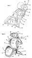
vehicle seating system 10 for fitment on a vehicle seat to support and restrain a child, according to an embodiment of the invention, is shown inFigures 1 and 2 . - The
seating system 10 includes first andsecond seating components seating component frame 16 over which aflexible membrane 18 is stretched to define a support surface. - In the embodiment shown in
Figures 1 and 2 , theseating system 10 also includes athird seating component 20 having a closedframe 16 over which aflexible membrane 18 is stretched to define a support surface, thethird seating component 20 being connected to thesecond seating component 14 to define a head rest. - The closed
frame 16 of each of theseating components flexible membrane 18 stretched over theframe 16 forms a contoured support surface. - In the embodiment shown in
Figures 1 and 2 , theframes 16 of theseating components seating system 10 to support the child and resist sideways movement of the child relative to theseating components Figures 3 and 4 , which show theseating component 12 forming the seat of the seating system 10 (Figure 3 ) and the corresponding frame 16 (Figure 4 ). - In the embodiment shown in
Figures 1 and 2 , theframes 16 of theseating components seating components flexible membrane 18 stretched over the associatedframe 16. This arrangement minimizes the amount of contact between a child seated in theseating system 10 and solid components (e.g. the frames 16). It therefore minimizes the risk of discomfort or injuries that may otherwise result from contact between a child seated in theseating system 10 and solid components in theseating system 10. - The
flexible membrane 18 stretched over theframe 16 of each of theseating components seating components seating system 10 from overheating in high ambient temperatures. - In the embodiment shown in
Figures 1 and 2 , theflexible membrane 18 is a porous breathable fabric in the form of a mesh fabric. - The use of
flexible membranes 18 in the form of mesh fabric is advantageous during fitment of theseating system 10 on a vehicle seat since it enables the user to see through theseating components - The first and
second components seating system 10 are preferably connected by means of a connecting arrangement, which includes a floorengaging support 22. - The floor-
engaging support 22 preferably assists in maintaining theseating system 10 in an upright position when placed on a flat surface, such as the floor. - In the embodiment shown in
Figures 1 and 2 , the connecting arrangement includes asupport frame 24 interconnecting theseating components support frame 24 is a curved, tubular structure connected to thefirst seating component 12 forming the seat, by means of thefloor engaging support 22, and extending generally upwards, behind thesecond seating component 14 forming the back, to thethird seating component 20 forming the head rest. - The connecting arrangement also preferably includes first and
second connector members second seating component 14 and thesupport frame 24 to mount thesecond seating component 14 on thesupport frame 24 for sliding movement along the length of thesupport frame 24. Thefirst connector member 30 is fixed at one end towards the bottom of thesecond seating component 14 and is slidably mounted at its other end on thesupport frame 24. Thesecond connector member 32 is fixed at one end towards the top of thesecond seating component 14 and is slidably mounted at its other end on thesupport frame 24. - Sliding engagement between the
connector members support frame 24 provides means for adjusting the position of thesecond seating component 14 relative to thefirst seating component 12, as exemplified by the relative positions of theseating components Figures 5 and 6 . - Preferably, the
second seating component 14 is adjustable through a range of predetermined positions relative to thefirst seating component 12 to accommodate children of different heights in theseating system 10. This helps to ensure that the correct ergonomic seating position for a child of a given height is provided. - To assist adjustment of the position of the
second seating component 14 relative to thefirst seating component 12, ascale 34 may be marked on thesupport frame 24 identifying positions of thesecond connector member 32 on thesupport frame 24 which correspond to positions of thesecond seating component 14 relative to the first seating component required to accommodate children of different heights. - Preferably, a
window 36 having amarker 38 is provided in thesecond connector member 32 through which thescale 34 may be viewed, as shown inFigures 7, 8 ,9a and 9b . - Such an arrangement allows a user to slide the
second seating component 14 along thesupport frame 24 until the height of the child intending to sit in theseating system 10 is aligned with themarker 38 shown in thewindow 36, as shown inFigures 10a and 10b . - Once the position of the
second seating component 14 relative to thefirst seating component 12 is adjusted as desired, it can be fixed in position on the support frame, preferably by means of alocking system 40, as shown inFigures 10a - 10d . This enables the position of thesecond seating component 14 relative to thefirst seating component 12 to be adjusted quickly and accurately for children of different heights without having to adopt a trial and error approach. - The locking
system 40 includes a plurality of equidistantly spaced recesses 42 formed along opposite edges of thesupport frame 24.Teeth 44 provided on thesecond connector component 32, on opposite sides of the support frame 24 (only one side being shown), are engageable within therecesses 42 to lock thesecond connector 32 in position, relative to thesupport frame 24, and prevent sliding movement of thesecond connector 32 on thesupport frame 24, as shown inFigure 10a . - The
teeth 44 are preferably mounted by means of pivot pins 46 that allow pivotal movement of theteeth 44 to move anengagement portion 48 of eachtooth 44 into and out of engagement with arespective recess 42. - Each
tooth 44 also preferably includes a cam portion (not shown) received within arelease member 50 slidably mounted on thesecond connector component 32 such that on sliding movement of therelease member 50 towards thesupport frame 24 therelease member 50 engages the cam portion of eachtooth 44 causing pivotal movement of thetooth 44 to move theengagement portion 48 of thetooth 44 out of engagement with therespective notch 42, as shown inFigure 10b . - When the
teeth 44 on each side of thesupport frame 24 are disengaged, thesecond connector member 32 is free to slide along thesupport frame 24, as shown inFigure 10c , and thereby allow adjustment of thesecond seating component 14 relative to thefirst seating component 12. - On sliding movement of the
release member 50 away from thesupport frame 24, once adjustment is complete, engagement between therelease member 50 and the cam portion of eachtooth 44 preferably causes pivotal movement of thetooth 44 to move theengagement portion 48 of thetooth 44 into engagement with anadjacent recess 42, as shown inFigure 10d . - Preferably the
release member 50 and theteeth 44 are resiliently biased such that therelease member 50 automatically moves away from thesupport frame 24 when released and. on movement of therelease member 50 away from thesupport frame 24 and out of engagement with the cam portion of eachtooth 44, a resilient biasing member causes pivotal movement of thetooth 44 to move theengagement portion 48 into engagement with arecess 42. This allows the provision of resiliently biased, depressible buttons on opposite sides of thesupport frame 24 to facilitate adjustment of thesecond seating component 14 relative to thefirst seating component 12. - Preferably, the connecting arrangement also includes a
third connector member 52 mounted on an elongate strut member 54 (Figure 11 ), which is slidably received within thesupport frame 24. - Sliding movement of the
strut member 54 into and out of thesupport frame 24 provides means for adjusting the position of thethird seating component 14 relative to thesecond seating component 14, as exemplified by the relative positions of theseating components Figures 5 and 6 . - When the
third seating component 20 is positioned in a desired position relative to thesecond seating component 14, the third seating component can be fixed in position relative to thesupport frame 24, preferably by means of a locking system. The locking system may take a similar form to thelocking system 40 associated with thesecond seating component 14. - In the embodiment shown in
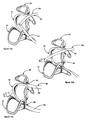
Figures 1 and 2 , the connecting arrangement defines spacedlocators vehicle seat belt 60 when theseat belt 60 is passed across theseating components seating system 10 on a vehicle seat. - The provision of the
locators seat belt 60 across the front of theseating components Figure 12a ) so as to align theshoulder strap 62 with an opening between the second andthird seating components waist strap 64 with an opening between the first andsecond seating components 12,14 (Figure 12b ). On tightening theseat belt 60 to increase the tension in the shoulder and waist straps 62,64 theshoulder strap 62 is pulled tightly against alocator 56 defined by thesupport frame 24 and thesecond connector member 32 and thewaist strap 64 is pulled tightly against alocator 58 defined by the floor-engaging support member 22 (Figure 12c ). Thelocators seating system 10 can be pulled tightly against the vehicle seat. - This arrangement enables a user to fit the
seating system 10 on a vehicle seat without having to locate theseat belt 60 though any connecting members provided on the rear of the seating system. Consequently the user does not need to be able to see and reach behind theseating system 10. - In the embodiment shown in
Figures 1 and 2 , theseating system 10 includes first andsecond stabilizer components seating system 10 to support theseating system 10 when it is fitted on a vehicle seat. - Preferably the
first stabilizer component 66 is formed integrally with thefloor engaging support 22 to define two laterally extendinglimbs Figures 7 and 8 . - Preferably, the
second stabilizer component 68 is mounted at or towards the top of thesupport frame 24 to define two laterally extendinglimbs 68a,6857b also defining contact points at their terminal ends, as shown inFigures 7 and 8 . Acontact pad limbs seating system 10 is fitted thereon and held against the vehicle seat by theseat belt 60. - The provision of the laterally spaced contact points supports the
seating system 10 when fitted on a vehicle seat, thereby preventing the seat system pivoting about thesupport frame 24 and ensuring that the seating system is stable on the vehicle seat. - The laterally spaced contact points together with a lower edge of the
first seating component 12, which is also preferably in contact with the vehicle seat when theseating system 10 is mounted on the vehicle seat (as shown inFigures 5 and 6 ), define a five-point contact arrangement to support theseating system 10 and assist in preventing twisting and tipping of theseating system 10 on the vehicle seat. Preferably, a child is restrained in theseating system 10 by means of a five-point strap system 70, as shown inFigure 13 . - The five-
point strap system 70 includes fourstatic fixing points 70a-70d on the frame of thesecond seating component 14 so that a strap passed over each shoulder of the child, and a strap extends around the waist of the child from opposite sides of thesecond seating component 14. - Preferably a
tensioning web 72 is secured at one end to theflexible membrane 18 of thefirst seating component 12 to extend between the legs of the child to meet the other straps at the middle of the child's waist. At this point, preferably thetensioning web 72 and the straps are interconnected by means ofbuckle 74. Thetensioning web 72 can then preferably be adjusted in length to increase tension in the shoulder straps and thereby ensure that the child is restrained securely in theseating system 10. - As can be seen in
Figure 2 , theseating components side bumper members respective frame 16. - Each of the
bumper members second seating components fin seating system 10 move towards therespective frame 16. - Each of the
bumper members 80 provided on thethird seating component 20 includes afin 86 formed from a resiliently deformable material, which deforms on contact so as to absorb energy should the head of a child sitting in theseating system 10 move towards therespective frame 16. - The provision of the
bumper members seating system 10 and therespective frames 16 when a vehicle in which theseating system 10 is fitted decelerates or turns, for example. - In other embodiments, the provision of vented and/or non-vented fins in the
bumper members bumper member 80 of thethird seating component 20 may include a ventedfin 86 as shown inFigure 14 . In yet further embodiments, thebumper members - A child
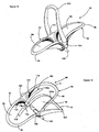
vehicle seating system 90 according to another embodiment of the invention is shown inFigures 15-18 . - The
seating system 90 includes first andsecond seating components seating components frame 96 over which amembrane 98 is stretched to define a support surface. - The
closed frame 96 of each of theseating components frame 96 forms a contoured surface. - In a similar manner to the embodiment described with reference to
Figures 1 and 2 , theframes 96 of theseating components seating system 90 to support the child and resist sideways movement of the child. - Similarly, the
frames 96 are shaped such that the support provided by each of theseating components flexible membrane 98 stretched over the associatedframe 96, thereby minimizing contact between a child seated in theseating system 90 and solid components of theseating system 90. - The
flexible membrane 98 is preferably a porous, breathable fabric to ventilate theseating components Figures 15-18 , is a mesh fabric. - The first and
second seating components support member 100, which preferably assists to maintain theseating system 90 in an upright position when theseating system 90 is positioned on a flat surface, such as the floor. - The connecting arrangement also preferably includes a
U-shaped handle 102, where the terminal ends of thehandle 102 are mounted toconnector members 104 connected between the first andsecond seating components seating system 90. - The
handle 102 is preferably mounted to each of theconnector members 104 by means of a pivot such that thehandle 102 is pivotal from a first, carrying, position where thehandle 102 extends above the first andsecond seating components Figures 15 and17 , to a second, support, position where thehandle 102 extends behind thesecond seating component 94, as shown inFigures 16 and18 . - In the embodiment shown in
Figures 15-18 , thesecond seating component 94 and the handle 102 (in its second support position) define spaced location points A, B (Figure 18 ) to locate a vehicle seat belt (not shown) when theseating system 90 is positioned on a vehicle seat such that a child seated in theseating system 90 faces the rear of the vehicle seat and the seat belt is passed around the back of theseating components - The shoulder strap is preferably located at location point A along an uppermost edge of the
frame 96 of thesecond seating component 94, and the waist strap is preferably located across the width of thehandle 102, at location point B, at a position spaced from the end of thehandle 102. - Preferably a child is restrained in the
seating system 90 by means of a three-point strap system 106, as shown inFigure 16 . - The three-
point strap system 106 preferably has twofixing points flexible membrane 98 of thesecond seating component 94 so that a strap passes over each shoulder of a child and extends towards their waist. - Preferably a
tensioning web 108 is secured at one to theflexible membrane 98 of thefirst seating component 92 to extend between the legs of the child to meet the other straps at the middle of the child's waist. At this point, preferably thetensioning web 108 and the straps are interconnected by means of abuckle 110. - The
tensioning web 108 can then preferably be adjusted in length to increase tension in the shoulder straps and thereby ensure that the child is restrained securely in theseating system 90.
As can be seen inFigure 15 , the first andsecond seating components respective frame 96. - Each of the bumper members 112,114 includes a vented
fin 116 formed from a resiliently deformable material, which deforms on contact so as to absorb energy should a child sitting in theseating system 90 move towards therespective frame 96. - As with the embodiment described with reference to
Figures 1 and 2 , the provision of the bumper members 112,114 further minimizes the risk of discomfort or injuries that may otherwise result from contact between a child seated in theseating system 90 and therespective frames 96 when a vehicle in which theseating system 90 is fitted decelerates or turns, for example. - In other embodiments, the bumper members 112,114 may include non-vented fins formed from a resiliently deformable material. In yet further embodiments the bumper members 112,114 may be omitted.
- A child
vehicle seating system 120 according to a yet further embodiment of the invention is shown inFigure 19 . - The
seating system 120 includes asingle seating component 122 defining a seat, theseating component 122 including aclosed frame 124 over which amembrane 126 is stretched to define a support surface. - The
closed frame 124 of theseating component 122 is preferably shaped so that theflexible membrane 126 stretched over theframe 124 forms a contoured surface. - In a similar manner to the embodiments described with reference to
Figures 1, 2 and15-18 , theframe 124 of theseating component 122 is shaped to curve around a child seated on theseating system 120 to support the child and resist sideways movement. - Similarly the
frame 124 is shaped such that the support provided by theseating component 122 is provided solely by theflexible membrane 126 stretched over theframe 124, thereby minimizing contact between a child seated on theseating system 120. - The
flexible membrane 126 is preferably a porous, breathable fabric to ventilate theseating component 122 and, in the embodiment shown inFigure 19 , is a mesh fabric. - In the embodiment shown in
Figure 19 , theseating component 122 includes abumper member 128 mounted on either side thereof along a section of theframe 124. Eachbumper member 128 includes a ventedfin 130 formed from a resiliently deformable material, which deforms on contact so as to absorb energy should a child sitting in theseating system 120 move towards theframe 124. - As with the embodiments described with reference to
Figures 1, 2 and15-18 , the provision of thebumper members 128 further minimizes the risk of discomfort or injuries that may otherwise result from contact between a child seated in theseating system 120 and theframe 124 when a vehicle in which theseating system 120 is fitted decelerates or turns, for example. - In other embodiments, the
seating component 122 may includebumper members 130 having non-vented fins formed from a resiliently deformable material. In yet further embodiments, thebumper members 130 may be omitted. - A
frame element 132, suitable for use in constructing theclosed frames 16,96,124 of each of the seating components of theseating systems 10,90,120 shown inFigures 1-19 , is shown in cross-section inFigures 20a-20f . - The
frame element 132 includes anelongate body 134 which, in cross-section, has a generally U-shaped profile defining spaced inner and outer limbs 136,138 depending from oneface 140 of a base 142 to form an openmouthed channel 144, as shown inFigure 20a . - The terminal ends 146,148 of the limbs 136,138 define a support to receive a
flexible membrane 150 stretched over the frame element, and theelongate body 134 is adapted to engage themembrane 150 when themembrane 150 is wrapped around theelongate body 134 and laid across the open mouth of thechannel 148, as shown inFigure 20b , to prevent themembrane 150 being drawn from theinner limb 136 towards theouter limb 138. - In the arrangement shown in
Figure 20b , this engagement is effected by means ofbarbs 152 provided along theterminal end 146 of theinner limb 136, which, in use, protrude into, and thereby grip, theflexible membrane 150. - The frame element also preferably includes a
rib 154 protruding from theopposite face 156 of the base 142 to the inner and outer limbs 136,138, in alignment with theouter limb 138. - The frame element may be a cast member or an extruded member depending on the material from which the frame element is formed.
- In use, one end of a
flexible membrane 150 is anchored along theterminal end 146 of theinner limb 136 of a frame element, along the inner edge of the open mouth of thechannel 144, by means of thebarbs 152. - The
membrane 150 is then wrapped around the frame element such that themembrane 150 overlies the open mouth of thechannel 144. - The
membrane 150 is then stretched around an opposed frame element (not shown) such that themembrane 150 overlies the open mouth of thechannel 144 in the opposed frame element, and is anchored to theterminal end 146 of theinner limb 136 of the opposed frame element, along the inner edge of the open mouth of thechannel 144 of the opposed frame element, by means of thebarbs 152. - The provision of the
rib 154 protruding from theopposite face 156 of thebase 142 of each of the frame elements acts to space themembrane 150 from thebase 142 of each of the frame elements. - In order to secure the
membrane 150 to each of the frame elements, and to increase the degree of stretch in themembrane 150, a push-inanchor member 158 may be inserted into the openmouthed channel 144 of each of the frame elements, as shown inFigures 20c and 20d . - On insertion of the push-in
anchor member 158 into the openmouthed channel 148 of each of the frame elements, themembrane 150 is drawn into thechannel 144 over theouter limb 138 of the respective frame element, thereby increasing the degree of tension in themembrane 150. - The push-in
anchor member 158 is preferably formed from a resiliently deformable material, and the inner and outer limbs 136,138 of each of the frame elements and the push-inanchor member 158 are preferably shaped to resist disengagement of the push-inanchor member 158 once the push-inanchor member 158 is inserted into therespective channel 144. - To resist creep of the
membrane 150 and the push-inanchor member 158 along the length of thechannel 144 in each frame element, the side walls of the inner and outer limbs 136,138 within thechannel 144 of each of the frame elements may include a plurality of spaced blade members (not shown) which engage themembrane 150 on insertion of the push-inanchor member 158 into thechannel 144. - In the embodiment shown in
Figures 20c and 20d , ashield 160 is attached along an outer edge of the push-inanchor member 158 in the form of a wing which can be folded over the outer edge of theelongate body 134 of the frame element to overlie themembrane 150 stretched around the frame element, as shown inFigures 20e and 20f . - The
shield 160 is preferably formed from a resiliently deformable material to protect themembrane 150 wrapped around the frame element, and may be formed integrally with the push-inanchor member 158. - In other arrangements, the
rib 154 may be omitted. - It is also envisaged that the base 142 need not be a continuous member extending along the entire length of the
frame element 132. The base 142 could in other arrangements include a plurality of equidistantly spacedbase members 142a extending between the inner and outer limbs 136,138 as shown inFigure 4 .
Claims (18)
- A child vehicle seating system, for fitment on a vehicle seat to support and restrain a child, comprising at least one seating component, characterized in the or each seating component including a closed frame over which a flexible membrane is stretched to define a support surface.
- A child vehicle seating system according to Claim 1 including at least first and second separate seating components interconnected to define a seat and a back, each seating component including a closed frame over which a flexible membrane is stretched to define a support surface.
- A child vehicle seating system according to Claim 2 further including a third separate seating component having a closed frame over which a flexible membrane is stretched to define a support surface, the first, second and third seating components being interconnected to define a seat, a back and a head rest.
- A child vehicle seating system according to any of the preceding claims wherein each of the closed frames is shaped such that the flexible membrane stretched over the frame forms a contoured support surface.
- A child vehicle seating system according to any of the preceding claims wherein the flexible membrane is formed from a porous breathable fabric.
- A child vehicle seating system according to Claim 5 wherein the porous breathable fabric is a mesh fabric.
- A child vehicle seating system according to Claim 2 and any claim dependent thereon wherein the first and second seating components are interconnected by means of a connecting arrangement including a floor-engaging support member.
- A child vehicle seating system according to Claim 7 wherein the connecting arrangement further includes a support frame interconnecting the seating components and including adjustment means to adjust the relative positions of the seating components through a range of predetermined positions to accommodate children of different heights.
- A child vehicle seating system according to any of the preceding claims further including spaced seat belt locators to receive and locate a vehicle seat belt when the seat belt is passed across the seating system in order to enable fitment of the seating system on a vehicle seat.
- A child vehicle seating system according to Claims 8 and 9 wherein the connecting arrangement defines the seat belt locators.
- A child vehicle seating system according to any of the preceding claims wherein the or each closed frame includes a frame element having an elongate body which in cross-section has a generally U-shaped profile defining spaced inner and outer limbs depending from one face of a base to form an open mouthed channel to receive a push-in anchor member, the terminal ends of the limbs defining a support to receive the flexible membrane stretched over the frame element and the elongate body being adapted to engage the membrane when wrapped around the elongate body and laid across the open mouth of the channel to prevent the membrane being drawn into the channel from the inner limb when a push-in anchor member is inserted into the channel so as to encourage the membrane to be drawn into the channel over the outer limb and thereby increase the degree of tension in the membrane.
- A child vehicle seating system according to Claim 11 wherein the inner limb includes a plurality of barbs which engage the flexible membrane when it is laid across the open mouth of the channel to prevent the membrane being drawn into the channel from the inner limb when a push-in anchor member is inserted into the channel so as to encourage the membrane to be drawn into the channel over the outer limb and thereby increase the degree of tension in the membrane.
- A child vehicle seating system according to Claim 11 or Claim 12 wherein the inner and outer limbs and the push-in anchor member are shaped to resist disengagement of the push-in member when the push-in anchor member is inserted into the channel.
- A child vehicle seating system according to any of Claims 11-13 wherein the elongate body further includes a rib protruding from the opposite face of the base to the limbs, in alignment with the outer limb, to guide the flexible membrane over the elongate body while spacing the membrane from the base.
- A child vehicle seating system according to any of Claims 11-14 wherein a plurality of spaced blade members are formed on the side walls of the limbs within the channel to engage the flexible membrane on insertion of the push-in anchor member into the channel and resist creep of the flexible membrane and the push-in anchor member in a direction along the length of the channel.
- A child vehicle seating system according to any of Claims 11-15 further including a resilient shield member attached to the push-in anchor member in the form of a wing which folds over the outer edge of the elongate body to overlie the flexible membrane stretched around the outer edge of the elongate body.
- A child vehicle seating system according to any of the preceding claims wherein the or at least one of the seating components includes a side bumper member mounted along a section of the respective frame at either side thereof to absorb energy from a child sitting in the child vehicle seating system as the child moves towards the respective frame.
- A child vehicle seating system according to Claim 17 wherein each side bumper member includes a vented fin formed from a resiliently deformable material which deforms on contact so as to absorb the energy from a child sitting in the child vehicle seating system as the child moves towards the respective frame.
Priority Applications (1)
| Application Number | Priority Date | Filing Date | Title |
|---|---|---|---|
| PL06744111T PL1893439T3 (en) | 2005-06-04 | 2006-06-05 | A child vehicle seating system |
Applications Claiming Priority (2)
| Application Number | Priority Date | Filing Date | Title |
|---|---|---|---|
| GBGB0511393.1A GB0511393D0 (en) | 2005-06-04 | 2005-06-04 | A seating system |
| PCT/GB2006/002057 WO2006131717A1 (en) | 2005-06-04 | 2006-06-05 | A child vehicle seating system |
Publications (2)
| Publication Number | Publication Date |
|---|---|
| EP1893439A1 EP1893439A1 (en) | 2008-03-05 |
| EP1893439B1 true EP1893439B1 (en) | 2010-12-15 |
Family
ID=34835130
Family Applications (1)
| Application Number | Title | Priority Date | Filing Date |
|---|---|---|---|
| EP06744111A Not-in-force EP1893439B1 (en) | 2005-06-04 | 2006-06-05 | A child vehicle seating system |
Country Status (9)
| Country | Link |
|---|---|
| US (1) | US8038212B2 (en) |
| EP (1) | EP1893439B1 (en) |
| CN (2) | CN101233012B (en) |
| AT (1) | ATE491597T1 (en) |
| DE (1) | DE602006018912D1 (en) |
| ES (1) | ES2382432T3 (en) |
| GB (2) | GB0511393D0 (en) |
| PL (1) | PL1893439T3 (en) |
| WO (1) | WO2006131717A1 (en) |
Families Citing this family (30)
| Publication number | Priority date | Publication date | Assignee | Title |
|---|---|---|---|---|
| CN101734177B (en) * | 2008-12-09 | 2012-07-04 | 好孩子儿童用品有限公司 | Car seat for children |
| US8454093B2 (en) | 2008-12-24 | 2013-06-04 | Mity-Lite, Inc. | Mesh chair with open-end hoop |
| US8317269B2 (en) | 2008-12-24 | 2012-11-27 | Mity-Lite, Inc. | Mesh stacking chair |
| US8033598B2 (en) | 2008-12-24 | 2011-10-11 | Mity-Lite, Inc. | Mesh folding chair |
| US8322787B2 (en) | 2008-12-24 | 2012-12-04 | Mity-Lite, Inc. | Clamping joint for a chair |
| EP2241475A1 (en) * | 2009-04-14 | 2010-10-20 | Anecia Sp. z o.o. | A seating portion of a car seat for children and a method for manufacturing thereof |
| US20110057497A1 (en) * | 2009-09-08 | 2011-03-10 | Tsan-Ching Wang | Combination of net and frame |
| USD648554S1 (en) | 2009-11-04 | 2011-11-15 | Mity-Lite, Inc. | Mesh stacking chair |
| FR2955535A1 (en) * | 2010-01-28 | 2011-07-29 | Dorel France Sa | CHILD CAR SEAT, INTENDED TO BE SOLIDARIZED AT THE SEAT OF A MOTOR VEHICLE. |
| USD660612S1 (en) | 2010-11-16 | 2012-05-29 | Mity-Lite, Inc. | Mesh banquet chair |
| KR20120107716A (en) * | 2011-03-22 | 2012-10-04 | 삼성테크윈 주식회사 | Temperature control apparatus for material |
| DE102011015348B4 (en) * | 2011-03-28 | 2015-07-16 | Grammer Aktiengesellschaft | vehicle seat |
| CN102555852B (en) * | 2012-01-06 | 2015-10-21 | 好孩子儿童用品有限公司 | Automobile seat for child |
| US20140021756A1 (en) * | 2012-07-19 | 2014-01-23 | Baby Matters LLC | Seat |
| USD697730S1 (en) | 2012-09-20 | 2014-01-21 | Steelcase Inc. | Chair |
| USD781605S1 (en) | 2015-04-24 | 2017-03-21 | Steelcase Inc. | Chair |
| USD698165S1 (en) | 2012-09-20 | 2014-01-28 | Steelcase Inc. | Chair |
| USD699959S1 (en) | 2012-09-20 | 2014-02-25 | Steelcase Inc. | Chair |
| USD699958S1 (en) | 2012-09-20 | 2014-02-25 | Steelcase Inc. | Chair |
| USD683151S1 (en) | 2012-09-20 | 2013-05-28 | Steelcase Inc. | Chair |
| WO2015195653A1 (en) * | 2014-06-16 | 2015-12-23 | Zodiac Seats Us Llc | Lightweight headrests with suspension mesh and supporting frame |
| USD781604S1 (en) | 2015-04-24 | 2017-03-21 | Steelcase Inc. | Chair |
| USD758774S1 (en) | 2015-04-24 | 2016-06-14 | Steelcase Inc. | Headrest assembly |
| USD760526S1 (en) | 2015-04-24 | 2016-07-05 | Steelcase Inc. | Headrest assembly |
| USD759415S1 (en) | 2015-04-24 | 2016-06-21 | Steelcase Inc. | Headrest |
| CA2936917C (en) | 2015-07-23 | 2018-05-22 | Dorel Juvenile Group, Inc. | Child restraint with energy management system |
| EP3823857A4 (en) * | 2018-07-16 | 2022-04-20 | Dong-in Entech Co., Ltd. | Portable car seat |
| US10703330B2 (en) * | 2018-10-16 | 2020-07-07 | GM Global Technology Operations LLC | Restraint harness attached to a main support structure of a vehicle |
| USD953758S1 (en) * | 2019-06-27 | 2022-06-07 | Bentley Motors Limited | Seat |
| US10960794B1 (en) * | 2019-11-05 | 2021-03-30 | GM Global Technology Operations LLC | Seat assembly |
Family Cites Families (63)
| Publication number | Priority date | Publication date | Assignee | Title |
|---|---|---|---|---|
| US462055A (en) | 1891-10-27 | Toast-cutter | ||
| GB623055A (en) | 1946-10-23 | 1949-05-11 | Annette Elsie Fridolph | Improvements in rails or beading |
| US3606453A (en) | 1968-10-29 | 1971-09-20 | James J Cicero | Seat belt extension assembly for child's chair |
| FR2277711A1 (en) | 1974-07-12 | 1976-02-06 | Stelniceanu Jacques | Foldable tubular pushchair with canvas seat - has elastic loops supporting top of seat on support rod |
| US3995882A (en) | 1975-04-14 | 1976-12-07 | Watkins Mervyn M | Folding support structure |
| US4364607A (en) | 1980-07-28 | 1982-12-21 | Gilardini S.P.A. | Seat for vehicles |
| GB2099376A (en) | 1981-04-09 | 1982-12-08 | Kirkmoss Ltd | Improvements in or relating to foldable pushchairs |
| DE3207352A1 (en) | 1982-03-02 | 1983-09-08 | Wilkhahn Wilkening + Hahne GmbH + Co, 3252 Bad Münder | ARMCHAIR |
| GB8323006D0 (en) | 1983-08-26 | 1983-09-28 | Serac Ltd | Clip fixing for retaining thin film |
| US4510634A (en) * | 1983-09-30 | 1985-04-16 | Diedrich Brian J | Infant carrier |
| US4602816A (en) * | 1984-09-04 | 1986-07-29 | General Motors Corporation | Motor vehicle sling seat |
| GB8604807D0 (en) | 1986-02-26 | 1986-04-03 | Carrington S P | Sheet fabric joining system |
| IT8920623V0 (en) | 1988-02-23 | 1989-02-23 | Abbasali Abdulla Currimjee | SITTING DEVICE. |
| CA2035797A1 (en) | 1990-08-08 | 1992-02-09 | Paul K. Meeker | Portable high chair/booster seat |
| DE4140638C2 (en) | 1991-12-10 | 1994-02-03 | Wuerstl Curt Vermoegensverwalt | Child safety seat |
| EP0856269B1 (en) * | 1992-06-15 | 2005-08-31 | Herman Miller, Inc. | Exposed fabric for a seating structure and method for making a chair with an exposed fabric |
| US5342111A (en) | 1992-12-21 | 1994-08-30 | General Motors Corporation | Retractable seat |
| GB9313227D0 (en) * | 1993-06-26 | 1993-08-11 | Britax Restmor Ltd | Pushchair |
| US5785382A (en) * | 1994-02-16 | 1998-07-28 | Bettacare Limited | Infant car seats |
| FR2735082B1 (en) | 1995-06-07 | 1998-06-05 | Ampafrance | CHILD SEAT |
| PT751033E (en) | 1995-06-30 | 2001-06-29 | Margarete Schrader | CHILD SEAT FOR CARS |
| DE19527351C2 (en) | 1995-07-26 | 1999-01-07 | Bayerische Motoren Werke Ag | child seat |
| JPH0939627A (en) | 1995-08-01 | 1997-02-10 | Molten Corp | Chair for infant |
| US5915787A (en) | 1996-04-23 | 1999-06-29 | Dme Corporation | Aircraft seat child restraint device |
| CN2294195Y (en) * | 1996-04-26 | 1998-10-14 | 陈丽琚 | Carriage for children with means able to position safety seat |
| DE29608894U1 (en) | 1996-05-17 | 1996-07-25 | Hartmann Johannes | Child seat to attach to an adult seat unit |
| US5964502A (en) | 1996-10-25 | 1999-10-12 | Evenflo Company, Inc. | High-back child restraint system |
| AU5094298A (en) * | 1996-11-04 | 1998-05-29 | Chrysler Corporation | Lightweight bucket seat for motor vehicles |
| JP2001503300A (en) | 1996-11-07 | 2001-03-13 | ペリー、チャールズ・オーエン | Flexible chair with adjustable support frame |
| US6105997A (en) | 1996-11-13 | 2000-08-22 | Convaid Products, Inc. | Stroller Arrangement |
| US5806924A (en) * | 1996-12-17 | 1998-09-15 | Cambridge Industries, Inc. | Baby seat |
| TW381996B (en) * | 1997-10-21 | 2000-02-11 | Delta Tooling Co Ltd | Cushion and seat having a net-shaped skin |
| JPH11198696A (en) | 1998-01-14 | 1999-07-27 | Takata Kk | Child seat |
| DE19906547B4 (en) | 1999-02-17 | 2004-03-25 | Innovint Einrichtungs Gmbh | Child seat for mobile use in an aircraft |
| US6254190B1 (en) | 1999-09-29 | 2001-07-03 | Peter G. G. Gregory | Chair having a seat with differential front and rear support portions |
| JP2001105942A (en) | 1999-10-12 | 2001-04-17 | Toyota Autom Loom Works Ltd | Child seat |
| JP2001294064A (en) | 2000-02-07 | 2001-10-23 | Aprica Kassai Inc | Safety child and junior seat for automobile |
| DE20005818U1 (en) | 2000-03-29 | 2001-08-02 | Koenig & Neurath Ag | Seat and / or backrest covering of a chair |
| GB2361865A (en) | 2000-05-06 | 2001-11-07 | Seymour Powell Ltd | Seat, such as aeroplane seat, with opening out/ rocking around common virtual axis action |
| NZ504871A (en) | 2000-05-22 | 2002-04-26 | Miller Herman Inc | A chair with a preload mechanism to assist in the manufacture of reclining chairs so that the spring mechanism may be easily inserted |
| US6439665B1 (en) | 2000-06-09 | 2002-08-27 | Stylex | Ergonomic chair with mesh seat and back |
| JP2002087121A (en) | 2000-09-20 | 2002-03-26 | Toyota Industries Corp | Child seat |
| US6540950B1 (en) * | 2000-09-20 | 2003-04-01 | Dahti, Inc. | Carrier and attachment method for load bearing fabric |
| JP2002120618A (en) | 2000-10-17 | 2002-04-23 | Toyota Industries Corp | Seat and stroller furnished with this seat |
| JP4903328B2 (en) | 2000-12-28 | 2012-03-28 | タカノ株式会社 | Membrane member mounting structure |
| JP2002211298A (en) | 2001-01-16 | 2002-07-31 | Mazda Motor Corp | Vehicular seat |
| US6575492B2 (en) * | 2001-03-26 | 2003-06-10 | Convaid Products, Inc. | Lateral torso supports for folding wheelchairs |
| US6623074B2 (en) | 2001-04-05 | 2003-09-23 | Mattel, Inc. | Vehicle seat |
| JP2003072435A (en) | 2001-09-06 | 2003-03-12 | Aprica Kassai Inc | Nursing utensil |
| NL1019017C2 (en) * | 2001-09-24 | 2003-03-25 | Revab Bv | Self-supporting seat support and wheelchair equipped with it, as well as a method for manufacturing it. |
| US7066536B2 (en) | 2002-02-11 | 2006-06-27 | Graco Children's Products Inc. | Child seat |
| US6644674B2 (en) | 2002-02-12 | 2003-11-11 | Cari-All, Inc. | Shopping cart with dedicated multi-compartments |
| GB0203733D0 (en) | 2002-02-16 | 2002-04-03 | Britax Excelsior | Foldable child seat |
| DE20203348U1 (en) | 2002-03-01 | 2002-08-22 | Saier Katrin | Three-wheeled stroller |
| GB0208678D0 (en) * | 2002-04-16 | 2002-05-29 | Britax Roemer Kindersicherheit Gmbh | Child safety seat |
| DE20308464U1 (en) * | 2002-06-20 | 2003-08-21 | Keiper Recaro Gmbh Co | Car safety seat for baby, comprising separately movable backrest and seat, for being also used as portable cot |
| NL1020910C2 (en) | 2002-06-20 | 2003-12-23 | Dremefa Bv | Child's seat. |
| EP1552771B1 (en) | 2002-07-23 | 2009-04-15 | Okamura corporation | Construction for attaching net member to chair seat or backrest frame |
| US6908151B2 (en) | 2003-03-07 | 2005-06-21 | Meeker R&D, Inc. | Adjustable and foldable booster car seat |
| US20050127735A1 (en) | 2003-11-03 | 2005-06-16 | Kenneth Munsch | Vehicle seat with adjustable support system |
| WO2005053998A1 (en) | 2003-12-05 | 2005-06-16 | Combi Corporation | Child seat |
| US20060071453A1 (en) * | 2004-10-01 | 2006-04-06 | Myers Peter J | Ventilated strollers and methods of ventilating strollers |
| US7152929B2 (en) * | 2005-04-20 | 2006-12-26 | Comfordy Co., Ltd. | Structure of a double-mesh seat of a chair |
-
2005
- 2005-06-04 GB GBGB0511393.1A patent/GB0511393D0/en not_active Ceased
-
2006
- 2006-06-05 WO PCT/GB2006/002057 patent/WO2006131717A1/en active Application Filing
- 2006-06-05 GB GB0719171A patent/GB2439020B/en not_active Expired - Fee Related
- 2006-06-05 CN CN2006800277925A patent/CN101233012B/en not_active Expired - Fee Related
- 2006-06-05 ES ES06744111T patent/ES2382432T3/en active Active
- 2006-06-05 US US11/921,720 patent/US8038212B2/en not_active Expired - Fee Related
- 2006-06-05 AT AT06744111T patent/ATE491597T1/en not_active IP Right Cessation
- 2006-06-05 PL PL06744111T patent/PL1893439T3/en unknown
- 2006-06-05 EP EP06744111A patent/EP1893439B1/en not_active Not-in-force
- 2006-06-05 CN CN2006800279634A patent/CN101233039B/en not_active Expired - Fee Related
- 2006-06-05 DE DE602006018912T patent/DE602006018912D1/en active Active
Also Published As
| Publication number | Publication date |
|---|---|
| GB0511393D0 (en) | 2005-07-13 |
| GB2439020A (en) | 2007-12-12 |
| WO2006131717A1 (en) | 2006-12-14 |
| ATE491597T1 (en) | 2011-01-15 |
| PL1893439T3 (en) | 2011-06-30 |
| CN101233039B (en) | 2012-01-04 |
| CN101233039A (en) | 2008-07-30 |
| GB2439020B (en) | 2009-01-14 |
| ES2382432T3 (en) | 2012-06-08 |
| US20090184548A1 (en) | 2009-07-23 |
| GB0719171D0 (en) | 2007-11-07 |
| CN101233012A (en) | 2008-07-30 |
| CN101233012B (en) | 2010-11-03 |
| US8038212B2 (en) | 2011-10-18 |
| DE602006018912D1 (en) | 2011-01-27 |
| EP1893439A1 (en) | 2008-03-05 |
Similar Documents
| Publication | Publication Date | Title |
|---|---|---|
| EP1893439B1 (en) | A child vehicle seating system | |
| US6916066B2 (en) | Infant car seat and safety belt system | |
| CN103507677B (en) | The safety belt lock catch of safety seat | |
| US20090309405A1 (en) | Child safety seat with adjustable headrest | |
| US20120019033A1 (en) | Booster cushion for use with a vehicle seat | |
| US20090230741A1 (en) | Child Restraint System | |
| GB2429641A (en) | Child safety seat with belt buckle positioning means | |
| US4738489A (en) | Child's car seat restraint system | |
| KR930012098B1 (en) | Child's car seat restraint system | |
| CN107264347A (en) | Booster seat with removable strip locator automotive seat | |
| KR102120985B1 (en) | Improved tether strap arrangement | |
| TW201221387A (en) | Child seat | |
| US20070052278A1 (en) | Portable child seat | |
| US20100078908A1 (en) | Stroller having a seat belt attachment and adjustment device | |
| EP1396378A1 (en) | Connecting system for child car seats | |
| EP2263911B1 (en) | Child vehicle seat for forwardly facing and rearwardly facing use | |
| US20100032460A1 (en) | Infant support device | |
| AU2005311274A1 (en) | Safety device for child seats for vehicles | |
| CN107685661A (en) | Motor vehicle Future Prospects of Child Restraint Systems for Vehicles | |
| WO2012129613A1 (en) | Restraint system for a child safety seat | |
| US20070102989A1 (en) | Restraint safety device | |
| JPS6316582Y2 (en) | ||
| US8590967B1 (en) | Child car safety seat | |
| RU2758230C2 (en) | Child safety seat | |
| US10800297B2 (en) | Systems, methods, and apparatuses for attaching soft goods to a child's apparatus |
Legal Events
| Date | Code | Title | Description |
|---|---|---|---|
| PUAI | Public reference made under article 153(3) epc to a published international application that has entered the european phase |
Free format text: ORIGINAL CODE: 0009012 |
|
| 17P | Request for examination filed |
Effective date: 20071207 |
|
| AK | Designated contracting states |
Kind code of ref document: A1 Designated state(s): AT BE BG CH CY CZ DE DK EE ES FI FR GB GR HU IE IS IT LI LT LU LV MC NL PL PT RO SE SI SK TR |
|
| DAX | Request for extension of the european patent (deleted) | ||
| 17Q | First examination report despatched |
Effective date: 20080812 |
|
| DAX | Request for extension of the european patent (deleted) | ||
| GRAP | Despatch of communication of intention to grant a patent |
Free format text: ORIGINAL CODE: EPIDOSNIGR1 |
|
| GRAS | Grant fee paid |
Free format text: ORIGINAL CODE: EPIDOSNIGR3 |
|
| GRAA | (expected) grant |
Free format text: ORIGINAL CODE: 0009210 |
|
| AK | Designated contracting states |
Kind code of ref document: B1 Designated state(s): AT BE BG CH CY CZ DE DK EE ES FI FR GB GR HU IE IS IT LI LT LU LV MC NL PL PT RO SE SI SK TR |
|
| REG | Reference to a national code |
Ref country code: CH Ref legal event code: EP Ref country code: GB Ref legal event code: FG4D |
|
| REG | Reference to a national code |
Ref country code: IE Ref legal event code: FG4D |
|
| REF | Corresponds to: |
Ref document number: 602006018912 Country of ref document: DE Date of ref document: 20110127 Kind code of ref document: P |
|
| REG | Reference to a national code |
Ref country code: NL Ref legal event code: T3 |
|
| REG | Reference to a national code |
Ref country code: SE Ref legal event code: TRGR |
|
| PG25 | Lapsed in a contracting state [announced via postgrant information from national office to epo] |
Ref country code: LT Free format text: LAPSE BECAUSE OF FAILURE TO SUBMIT A TRANSLATION OF THE DESCRIPTION OR TO PAY THE FEE WITHIN THE PRESCRIBED TIME-LIMIT Effective date: 20101215 |
|
| LTIE | Lt: invalidation of european patent or patent extension |
Effective date: 20101215 |
|
| PG25 | Lapsed in a contracting state [announced via postgrant information from national office to epo] |
Ref country code: LV Free format text: LAPSE BECAUSE OF FAILURE TO SUBMIT A TRANSLATION OF THE DESCRIPTION OR TO PAY THE FEE WITHIN THE PRESCRIBED TIME-LIMIT Effective date: 20101215 Ref country code: AT Free format text: LAPSE BECAUSE OF FAILURE TO SUBMIT A TRANSLATION OF THE DESCRIPTION OR TO PAY THE FEE WITHIN THE PRESCRIBED TIME-LIMIT Effective date: 20101215 Ref country code: FI Free format text: LAPSE BECAUSE OF FAILURE TO SUBMIT A TRANSLATION OF THE DESCRIPTION OR TO PAY THE FEE WITHIN THE PRESCRIBED TIME-LIMIT Effective date: 20101215 Ref country code: CY Free format text: LAPSE BECAUSE OF FAILURE TO SUBMIT A TRANSLATION OF THE DESCRIPTION OR TO PAY THE FEE WITHIN THE PRESCRIBED TIME-LIMIT Effective date: 20101215 Ref country code: SI Free format text: LAPSE BECAUSE OF FAILURE TO SUBMIT A TRANSLATION OF THE DESCRIPTION OR TO PAY THE FEE WITHIN THE PRESCRIBED TIME-LIMIT Effective date: 20101215 Ref country code: BG Free format text: LAPSE BECAUSE OF FAILURE TO SUBMIT A TRANSLATION OF THE DESCRIPTION OR TO PAY THE FEE WITHIN THE PRESCRIBED TIME-LIMIT Effective date: 20110315 |
|
| REG | Reference to a national code |
Ref country code: PL Ref legal event code: T3 |
|
| PG25 | Lapsed in a contracting state [announced via postgrant information from national office to epo] |
Ref country code: IS Free format text: LAPSE BECAUSE OF FAILURE TO SUBMIT A TRANSLATION OF THE DESCRIPTION OR TO PAY THE FEE WITHIN THE PRESCRIBED TIME-LIMIT Effective date: 20110415 Ref country code: CZ Free format text: LAPSE BECAUSE OF FAILURE TO SUBMIT A TRANSLATION OF THE DESCRIPTION OR TO PAY THE FEE WITHIN THE PRESCRIBED TIME-LIMIT Effective date: 20101215 Ref country code: PT Free format text: LAPSE BECAUSE OF FAILURE TO SUBMIT A TRANSLATION OF THE DESCRIPTION OR TO PAY THE FEE WITHIN THE PRESCRIBED TIME-LIMIT Effective date: 20110415 Ref country code: EE Free format text: LAPSE BECAUSE OF FAILURE TO SUBMIT A TRANSLATION OF THE DESCRIPTION OR TO PAY THE FEE WITHIN THE PRESCRIBED TIME-LIMIT Effective date: 20101215 Ref country code: BE Free format text: LAPSE BECAUSE OF FAILURE TO SUBMIT A TRANSLATION OF THE DESCRIPTION OR TO PAY THE FEE WITHIN THE PRESCRIBED TIME-LIMIT Effective date: 20101215 Ref country code: GR Free format text: LAPSE BECAUSE OF FAILURE TO SUBMIT A TRANSLATION OF THE DESCRIPTION OR TO PAY THE FEE WITHIN THE PRESCRIBED TIME-LIMIT Effective date: 20110316 |
|
| PG25 | Lapsed in a contracting state [announced via postgrant information from national office to epo] |
Ref country code: RO Free format text: LAPSE BECAUSE OF FAILURE TO SUBMIT A TRANSLATION OF THE DESCRIPTION OR TO PAY THE FEE WITHIN THE PRESCRIBED TIME-LIMIT Effective date: 20101215 Ref country code: SK Free format text: LAPSE BECAUSE OF FAILURE TO SUBMIT A TRANSLATION OF THE DESCRIPTION OR TO PAY THE FEE WITHIN THE PRESCRIBED TIME-LIMIT Effective date: 20101215 |
|
| PLBE | No opposition filed within time limit |
Free format text: ORIGINAL CODE: 0009261 |
|
| STAA | Information on the status of an ep patent application or granted ep patent |
Free format text: STATUS: NO OPPOSITION FILED WITHIN TIME LIMIT |
|
| PG25 | Lapsed in a contracting state [announced via postgrant information from national office to epo] |
Ref country code: DK Free format text: LAPSE BECAUSE OF FAILURE TO SUBMIT A TRANSLATION OF THE DESCRIPTION OR TO PAY THE FEE WITHIN THE PRESCRIBED TIME-LIMIT Effective date: 20101215 |
|
| 26N | No opposition filed |
Effective date: 20110916 |
|
| REG | Reference to a national code |
Ref country code: DE Ref legal event code: R097 Ref document number: 602006018912 Country of ref document: DE Effective date: 20110916 |
|
| REG | Reference to a national code |
Ref country code: CH Ref legal event code: PL |
|
| REG | Reference to a national code |
Ref country code: IE Ref legal event code: MM4A |
|
| PG25 | Lapsed in a contracting state [announced via postgrant information from national office to epo] |
Ref country code: LI Free format text: LAPSE BECAUSE OF NON-PAYMENT OF DUE FEES Effective date: 20110630 Ref country code: CH Free format text: LAPSE BECAUSE OF NON-PAYMENT OF DUE FEES Effective date: 20110630 Ref country code: IE Free format text: LAPSE BECAUSE OF NON-PAYMENT OF DUE FEES Effective date: 20110605 |
|
| REG | Reference to a national code |
Ref country code: ES Ref legal event code: FG2A Ref document number: 2382432 Country of ref document: ES Kind code of ref document: T3 Effective date: 20120608 |
|
| PG25 | Lapsed in a contracting state [announced via postgrant information from national office to epo] |
Ref country code: MC Free format text: LAPSE BECAUSE OF NON-PAYMENT OF DUE FEES Effective date: 20110630 |
|
| PG25 | Lapsed in a contracting state [announced via postgrant information from national office to epo] |
Ref country code: LU Free format text: LAPSE BECAUSE OF NON-PAYMENT OF DUE FEES Effective date: 20110605 |
|
| PGFP | Annual fee paid to national office [announced via postgrant information from national office to epo] |
Ref country code: SE Payment date: 20130612 Year of fee payment: 8 |
|
| PGFP | Annual fee paid to national office [announced via postgrant information from national office to epo] |
Ref country code: PL Payment date: 20130415 Year of fee payment: 8 |
|
| PG25 | Lapsed in a contracting state [announced via postgrant information from national office to epo] |
Ref country code: TR Free format text: LAPSE BECAUSE OF FAILURE TO SUBMIT A TRANSLATION OF THE DESCRIPTION OR TO PAY THE FEE WITHIN THE PRESCRIBED TIME-LIMIT Effective date: 20101215 |
|
| PG25 | Lapsed in a contracting state [announced via postgrant information from national office to epo] |
Ref country code: HU Free format text: LAPSE BECAUSE OF FAILURE TO SUBMIT A TRANSLATION OF THE DESCRIPTION OR TO PAY THE FEE WITHIN THE PRESCRIBED TIME-LIMIT Effective date: 20101215 |
|
| REG | Reference to a national code |
Ref country code: GB Ref legal event code: 732E Free format text: REGISTERED BETWEEN 20140313 AND 20140319 |
|
| REG | Reference to a national code |
Ref country code: DE Ref legal event code: R082 Ref document number: 602006018912 Country of ref document: DE Representative=s name: PATENTANWAELTE FREISCHEM, DE |
|
| REG | Reference to a national code |
Ref country code: FR Ref legal event code: TP Owner name: MAXI MILIAAN B.V., NL Effective date: 20140414 |
|
| REG | Reference to a national code |
Ref country code: DE Ref legal event code: R082 Ref document number: 602006018912 Country of ref document: DE Representative=s name: PATENTANWAELTE FREISCHEM, DE Effective date: 20140414 Ref country code: DE Ref legal event code: R081 Ref document number: 602006018912 Country of ref document: DE Owner name: MAXI MILIAAN B.V., NL Free format text: FORMER OWNER: SPACE NET TECHNOLOGY LTD., MORTON, NR. SOUTHWELL, GB Effective date: 20140414 Ref country code: DE Ref legal event code: R081 Ref document number: 602006018912 Country of ref document: DE Owner name: MAXI MILIAAN B.V., NL Free format text: FORMER OWNER: SPACE NET TECHNOLOGY LTD., MORTON, NR. SOUTHWELL, NOTTINGHAMSHIRE, GB Effective date: 20140414 Ref country code: DE Ref legal event code: R082 Ref document number: 602006018912 Country of ref document: DE Representative=s name: FREISCHEM & PARTNER PATENTANWAELTE MBB, DE Effective date: 20140414 |
|
| PG25 | Lapsed in a contracting state [announced via postgrant information from national office to epo] |
Ref country code: SE Free format text: LAPSE BECAUSE OF NON-PAYMENT OF DUE FEES Effective date: 20140606 |
|
| REG | Reference to a national code |
Ref country code: SE Ref legal event code: EUG |
|
| REG | Reference to a national code |
Ref country code: PL Ref legal event code: LAPE |
|
| PG25 | Lapsed in a contracting state [announced via postgrant information from national office to epo] |
Ref country code: PL Free format text: LAPSE BECAUSE OF NON-PAYMENT OF DUE FEES Effective date: 20140605 |
|
| REG | Reference to a national code |
Ref country code: FR Ref legal event code: PLFP Year of fee payment: 11 |
|
| PGFP | Annual fee paid to national office [announced via postgrant information from national office to epo] |
Ref country code: NL Payment date: 20160524 Year of fee payment: 11 |
|
| PGFP | Annual fee paid to national office [announced via postgrant information from national office to epo] |
Ref country code: ES Payment date: 20160614 Year of fee payment: 11 |
|
| PGFP | Annual fee paid to national office [announced via postgrant information from national office to epo] |
Ref country code: IT Payment date: 20160628 Year of fee payment: 11 |
|
| REG | Reference to a national code |
Ref country code: FR Ref legal event code: PLFP Year of fee payment: 12 |
|
| REG | Reference to a national code |
Ref country code: NL Ref legal event code: MM Effective date: 20170701 |
|
| PG25 | Lapsed in a contracting state [announced via postgrant information from national office to epo] |
Ref country code: NL Free format text: LAPSE BECAUSE OF NON-PAYMENT OF DUE FEES Effective date: 20170701 |
|
| PG25 | Lapsed in a contracting state [announced via postgrant information from national office to epo] |
Ref country code: IT Free format text: LAPSE BECAUSE OF NON-PAYMENT OF DUE FEES Effective date: 20170605 |
|
| REG | Reference to a national code |
Ref country code: FR Ref legal event code: PLFP Year of fee payment: 13 |
|
| PGFP | Annual fee paid to national office [announced via postgrant information from national office to epo] |
Ref country code: GB Payment date: 20180620 Year of fee payment: 13 |
|
| REG | Reference to a national code |
Ref country code: ES Ref legal event code: FD2A Effective date: 20181116 |
|
| PG25 | Lapsed in a contracting state [announced via postgrant information from national office to epo] |
Ref country code: ES Free format text: LAPSE BECAUSE OF NON-PAYMENT OF DUE FEES Effective date: 20170606 |
|
| PGFP | Annual fee paid to national office [announced via postgrant information from national office to epo] |
Ref country code: DE Payment date: 20190619 Year of fee payment: 14 |
|
| PGFP | Annual fee paid to national office [announced via postgrant information from national office to epo] |
Ref country code: FR Payment date: 20190619 Year of fee payment: 14 |
|
| GBPC | Gb: european patent ceased through non-payment of renewal fee |
Effective date: 20190605 |
|
| PG25 | Lapsed in a contracting state [announced via postgrant information from national office to epo] |
Ref country code: GB Free format text: LAPSE BECAUSE OF NON-PAYMENT OF DUE FEES Effective date: 20190605 |
|
| REG | Reference to a national code |
Ref country code: DE Ref legal event code: R119 Ref document number: 602006018912 Country of ref document: DE |
|
| PG25 | Lapsed in a contracting state [announced via postgrant information from national office to epo] |
Ref country code: FR Free format text: LAPSE BECAUSE OF NON-PAYMENT OF DUE FEES Effective date: 20200630 |
|
| PG25 | Lapsed in a contracting state [announced via postgrant information from national office to epo] |
Ref country code: DE Free format text: LAPSE BECAUSE OF NON-PAYMENT OF DUE FEES Effective date: 20210101 |