EP1893390B1 - Apparatus for slicing apples - Google Patents
Apparatus for slicing apples Download PDFInfo
- Publication number
- EP1893390B1 EP1893390B1 EP06773691A EP06773691A EP1893390B1 EP 1893390 B1 EP1893390 B1 EP 1893390B1 EP 06773691 A EP06773691 A EP 06773691A EP 06773691 A EP06773691 A EP 06773691A EP 1893390 B1 EP1893390 B1 EP 1893390B1
- Authority
- EP
- European Patent Office
- Prior art keywords
- blade
- blades
- clinch
- buckles
- buckle
- Prior art date
- Legal status (The legal status is an assumption and is not a legal conclusion. Google has not performed a legal analysis and makes no representation as to the accuracy of the status listed.)
- Active
Links
Images





Classifications
-
- A—HUMAN NECESSITIES
- A23—FOODS OR FOODSTUFFS; TREATMENT THEREOF, NOT COVERED BY OTHER CLASSES
- A23N—MACHINES OR APPARATUS FOR TREATING HARVESTED FRUIT, VEGETABLES OR FLOWER BULBS IN BULK, NOT OTHERWISE PROVIDED FOR; PEELING VEGETABLES OR FRUIT IN BULK; APPARATUS FOR PREPARING ANIMAL FEEDING- STUFFS
- A23N4/00—Machines for stoning fruit or removing seed-containing sections from fruit, characterised by their stoning or removing device
- A23N4/22—Machines for stoning fruit or removing seed-containing sections from fruit, characterised by their stoning or removing device for both splitting and stoning
-
- A—HUMAN NECESSITIES
- A23—FOODS OR FOODSTUFFS; TREATMENT THEREOF, NOT COVERED BY OTHER CLASSES
- A23N—MACHINES OR APPARATUS FOR TREATING HARVESTED FRUIT, VEGETABLES OR FLOWER BULBS IN BULK, NOT OTHERWISE PROVIDED FOR; PEELING VEGETABLES OR FRUIT IN BULK; APPARATUS FOR PREPARING ANIMAL FEEDING- STUFFS
- A23N15/00—Machines or apparatus for other treatment of fruits or vegetables for human purposes; Machines or apparatus for topping or skinning flower bulbs
- A23N15/06—Devices for other treatment of fruit, e.g. marking, maturing, polishing
-
- A—HUMAN NECESSITIES
- A23—FOODS OR FOODSTUFFS; TREATMENT THEREOF, NOT COVERED BY OTHER CLASSES
- A23N—MACHINES OR APPARATUS FOR TREATING HARVESTED FRUIT, VEGETABLES OR FLOWER BULBS IN BULK, NOT OTHERWISE PROVIDED FOR; PEELING VEGETABLES OR FRUIT IN BULK; APPARATUS FOR PREPARING ANIMAL FEEDING- STUFFS
- A23N4/00—Machines for stoning fruit or removing seed-containing sections from fruit, characterised by their stoning or removing device
- A23N4/12—Machines for stoning fruit or removing seed-containing sections from fruit, characterised by their stoning or removing device for coring fruit
- A23N4/14—Machines for stoning fruit or removing seed-containing sections from fruit, characterised by their stoning or removing device for coring fruit for apples, pears or the like
-
- B—PERFORMING OPERATIONS; TRANSPORTING
- B26—HAND CUTTING TOOLS; CUTTING; SEVERING
- B26D—CUTTING; DETAILS COMMON TO MACHINES FOR PERFORATING, PUNCHING, CUTTING-OUT, STAMPING-OUT OR SEVERING
- B26D1/00—Cutting through work characterised by the nature or movement of the cutting member or particular materials not otherwise provided for; Apparatus or machines therefor; Cutting members therefor
- B26D1/01—Cutting through work characterised by the nature or movement of the cutting member or particular materials not otherwise provided for; Apparatus or machines therefor; Cutting members therefor involving a cutting member which does not travel with the work
- B26D1/547—Cutting through work characterised by the nature or movement of the cutting member or particular materials not otherwise provided for; Apparatus or machines therefor; Cutting members therefor involving a cutting member which does not travel with the work having a wire-like cutting member
- B26D1/553—Cutting through work characterised by the nature or movement of the cutting member or particular materials not otherwise provided for; Apparatus or machines therefor; Cutting members therefor involving a cutting member which does not travel with the work having a wire-like cutting member with a plurality of wire-like cutting members
-
- B—PERFORMING OPERATIONS; TRANSPORTING
- B26—HAND CUTTING TOOLS; CUTTING; SEVERING
- B26D—CUTTING; DETAILS COMMON TO MACHINES FOR PERFORATING, PUNCHING, CUTTING-OUT, STAMPING-OUT OR SEVERING
- B26D3/00—Cutting work characterised by the nature of the cut made; Apparatus therefor
- B26D3/24—Cutting work characterised by the nature of the cut made; Apparatus therefor to obtain segments other than slices, e.g. cutting pies
- B26D3/26—Cutting work characterised by the nature of the cut made; Apparatus therefor to obtain segments other than slices, e.g. cutting pies specially adapted for cutting fruit or vegetables, e.g. for onions
-
- B—PERFORMING OPERATIONS; TRANSPORTING
- B26—HAND CUTTING TOOLS; CUTTING; SEVERING
- B26D—CUTTING; DETAILS COMMON TO MACHINES FOR PERFORATING, PUNCHING, CUTTING-OUT, STAMPING-OUT OR SEVERING
- B26D1/00—Cutting through work characterised by the nature or movement of the cutting member or particular materials not otherwise provided for; Apparatus or machines therefor; Cutting members therefor
- B26D1/0006—Cutting members therefor
-
- B—PERFORMING OPERATIONS; TRANSPORTING
- B26—HAND CUTTING TOOLS; CUTTING; SEVERING
- B26D—CUTTING; DETAILS COMMON TO MACHINES FOR PERFORATING, PUNCHING, CUTTING-OUT, STAMPING-OUT OR SEVERING
- B26D1/00—Cutting through work characterised by the nature or movement of the cutting member or particular materials not otherwise provided for; Apparatus or machines therefor; Cutting members therefor
- B26D1/01—Cutting through work characterised by the nature or movement of the cutting member or particular materials not otherwise provided for; Apparatus or machines therefor; Cutting members therefor involving a cutting member which does not travel with the work
- B26D1/46—Cutting through work characterised by the nature or movement of the cutting member or particular materials not otherwise provided for; Apparatus or machines therefor; Cutting members therefor involving a cutting member which does not travel with the work having an endless band-knife or the like
- B26D1/48—Cutting through work characterised by the nature or movement of the cutting member or particular materials not otherwise provided for; Apparatus or machines therefor; Cutting members therefor involving a cutting member which does not travel with the work having an endless band-knife or the like with tensioning means
-
- B—PERFORMING OPERATIONS; TRANSPORTING
- B26—HAND CUTTING TOOLS; CUTTING; SEVERING
- B26D—CUTTING; DETAILS COMMON TO MACHINES FOR PERFORATING, PUNCHING, CUTTING-OUT, STAMPING-OUT OR SEVERING
- B26D1/00—Cutting through work characterised by the nature or movement of the cutting member or particular materials not otherwise provided for; Apparatus or machines therefor; Cutting members therefor
- B26D1/0006—Cutting members therefor
- B26D2001/0033—Cutting members therefor assembled from multiple blades
-
- B—PERFORMING OPERATIONS; TRANSPORTING
- B26—HAND CUTTING TOOLS; CUTTING; SEVERING
- B26D—CUTTING; DETAILS COMMON TO MACHINES FOR PERFORATING, PUNCHING, CUTTING-OUT, STAMPING-OUT OR SEVERING
- B26D7/00—Details of apparatus for cutting, cutting-out, stamping-out, punching, perforating, or severing by means other than cutting
- B26D7/26—Means for mounting or adjusting the cutting member; Means for adjusting the stroke of the cutting member
- B26D7/2614—Means for mounting the cutting member
Definitions
- the present invention relates generally to slicing of apples.
- the present invention is designed to automatically slice apples into wedges for use in packaged fruit salads sold in restaurants or in packaged sliced fruit sold, for example, in supermarkets. More particularly, the present invention relates to an apparatus for optimizing the slicing of apples which results in minimum cell damage to the apple which, in turn, extends the shelf-life of packaged apple slices.
- the browning of freshly cut apples is caused by oxidation of one or more enzymes released from apple cells that are cut open or ruptured during the slicing operation.
- the enzymes are liquid and tend to spread across the freshly cut apple surface. As those enzymes oxidize, they turn brown. This oxidation process is described in detail in U.S. patent 6,054,160 at column 1, line 13 through column 3, line 16.
- the prior art includes various attempts to delay or prevent the browning of sliced apples.
- the prior art includes a variety of liquids that are applied to sliced apples in an attempt to neutralize the enzymes or to otherwise delay the onset of browning (see U.S. patents 5,922,382 ; 5,914,143 ; 5,939,117 ; 5,922,382 and 6,054,160 .
- the primary dis-advantage of this approach is that the apple slices tend to absorb the applied liquid (which is usually applied in the form of a bath or spray) and become "waterlogged,” losing their crispness and desirability, thereby becoming unacceptable to consumers.
- the prior art also includes the use of transparent plastic covers for packaged salads or apple slices to reduce the amount of oxygen in the ambient air that reaches the sliced apple surfaces (see U.S. patents 5,922,382 and 6,054,160 ).
- This technique covers the entire packaged salad (rather than sealing each cut surface), allowing ambient oxygen inside the package to react with the freshly cut apple surfaces.
- transparent covers are relatively expensive and not totally impermeable to air and allow oxygen and air to pass through over time.
- the prior art includes several genetically engineered species of apple tree wherein the apples have a delayed onset of browning after being sliced (see U.S. plant patents 4,956; 7,857; 13,930 and U.S. 2006/0053517P1).
- the difficulty with a genetically engineered apple is that the taste does not satisfy the large majority of consumers who favor the taste of known varietals such as Fuji, Granny Smith, Delicious and a host of others.
- U.S. patent 4,007,676 owned-by the assignee of the present application.
- the '676 patent teaches an apple slicer for cutting wedge shaped apple slices.
- the blades have a thickness of about 500 microns (0.020 inches) and are tensioned by a pair of screws (see column 9, lines 48-69). Applicants have found that simply tensioning the blade with the tensioning screws of the '676 patent is inadequate when using blades thinner than 500 microns.
- US 3,948,161 upon which the preamble of claim 1 is based A describes a multi-lane machine for removing the seed cell from previously cored apples by selectively cutting a cavity therein.
- Various size apples are accommodated and the size of the seed cell cavity is varied depending on the size of the apple.
- the apples are conveyed along a path while the core hole is oriented relative to the path. Taking advantage of the alignment of the core hole, the apples are transferred onto a spindle and moved therealong by a pair of centering jaws to a seed cell station.
- the medial plane of the apple is positioned over a seed celling knife on the spindle while the size of the apple is measured as it is moved into the seed celling station.
- the knife is crescent-shaped and pivotally housed in and rotated by the spindle.
- a knife control mechanism extends the rotating knife into the seed cell a distance determinate of the size of the apple and in timed sequence with the movement of the jaws. Subsequently, the apple is displaced along the spindle and through a die to cut the apple in segments.
- EP 0873828 A2 describes a wedge cut cutter for food products which includes one or more cutter sections mounted between a base plate and an end retainer. Each cutter section includes shoulders and clamping members for clamping each end of one or more elongate blades to the cutter section. Each blade is tensioned by an adjustment screw which bears against a roll pin which, in turn, urges a portion of the blade around a pair of anvils into a recess. The blades of each cutter section, or of adjacent cutter sections, are radially offset to cut incoming items into wedge-shaped portions.
- US 2002/124709 A1 describes a blade assembly for cutting a food product such as potatoes or vegetables in a wedge configuration.
- the blade assembly includes a blade head to which a blade is attached and tensioned by a tensioning assembly.
- the blade is attached to the blade head with a first end restrained by a first end retainer, a second end restrained by a second end retainer, a first bend positioned about a first return of the blade head, a second bend positioned about a second return of the blade head.
- the blade also includes a first leg segment extending in a first plane across an aperture of the blade head, and a second leg segment extending across the aperture of the blade head in a second plane at an angle to the first leg segment.
- the blade assembly for cutting a food product may also include a blade failure sensing device.
- the problem addressed by the present invention is how known varieties of apples can be sliced and packaged in a manner to delay the onset of browning while preserving crispness and taste.
- the present invention significantly delays the onset of browning white preserving crispness and taste.
- a key aspect of the present invention is the use of a significantly thinner blade than heretofore used in automatic apple slicing machines.
- the thinner blade must be used together with a novel system or supporting and tensioning the blade to resist bending, warping, and twisting as described below.
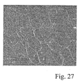
- the thickness of the blade utilized in the present invention is roughly equivalent to the diameter of most apple cells, i.e., less than 300 microns and preferably about 200 microns. As shown in Fig. 27 , typical apple cells are roughly 250-300 microns in width.
- Fig. 27 is a reproduction of Fig.
- Fig. 27 illustrates that the present invention has reduced the blade thickness by roughly the width of a typical apple cell. A reduction of such magnitude will inherently reduce the amount of apple cell damage caused by the slicing operation. Applicants are not aware of prior art apple slicing blades having a thickness less than about 500 microns.
- the use of a 200 micron thick blade cuts or ruptures less than half the cells that are cut or ruptured by a prior art blade of 500 micron thickness.
- the swath or kerf of the thinner blade is less than half that of a 500 micron thick blade.
- the reduction of the number of cut or ruptured apple cells inherently delays the onset of browning by reducing the amount of oxidizable enzymes released by cut or ruptured cells.
- the reduced volume of oxidizable enzymes is neutralized by known agents applied in much lower quantities than utilized in prior art apple slicers, thereby avoiding "waterlogged" apple slices while preserving crispness and a fresh appearance. Additionally, significant cost savings are realized by the use of a smaller volume of sealant and/or neutralizing agents.
- a first embodiment of the present invention utilizes a plurality of generally V-shaped blades having bent tabs at the outer ends or tips of the legs of each blade, wherein each blade is independently supported and tensioned.
- the apex (or “inner end") of each V-shaped blade is supported by a central hub; the bent tabs formed at the two outer ends of the blade are rigidly connected to and supported by a clinch buckle to stiffen the blade.
- each clinch buckle is preferably "captured” between two surfaces of the outer blade support ring to prevent rotation of the clinch buckles, thereby further stiffening the blades.
- An adjustable tensioning device is used to move or draw the clinch buckle radially outwardly and away from the inner hub or blade apex toward the outer blade support ring
- a plurality of single blades extends between a central or inner hub and a cylindrical outer blade support ring. Both ends of the blade are firmly and rigidly supported. The outer ends of each blade are connected to a clinch buckle as briefly noted above, and each clinch buckle is in turn adjustably mounted to the outer blade support ring for blade tensioning. Each blade is separately and independently tensioned from the exterior of the outer blade support ring.
- A-primary object is to provide an apparatus for automatically slicing apples which minimizes apple cell damage and delays the onset of browning, while preserving crispness and taste.
- a further object is to provide an apparatus for automatically slicing apples wherein a significantly thinner blade is used as compared with prior art apple slicers, and wherein the thinner blade is supported and tensioned to minimize and/or eliminate bending of the blade and to minimize apple cell damage.
- Figs. 1-11 illustrate a first embodiment of apple slicer assembly 10 of the present invention.
- Fig. 1 is a perspective view of a fully assembled slicer 10 and
- Fig. 2 is an exploded view.
- the slicer assembly 10 is used in conjunction with an apple orienting, coring and slicing machine such as that shown in U.S. patent 4,007,676 , incorporated herein by reference as though set forth in full.
- an apple orienting, coring and slicing machine such as that shown in U.S. patent 4,007,676 , incorporated herein by reference as though set forth in full.
- the orienting, conveying and coring aspects of the apparatus are not repeated here.
- Some updated versions of the apparatus (not pertinent to the slicer assembly) of the '676 patent are available from Atlas. Pacific Engineering Company of Pueblo, Colorado, and are not repeated here
- an outer blade support ring 20 is provided, and an inner hub 30 is positioned preferably at the center of the circle formed by ring 20.
- a circular array of blades 40 extends from inner blade support hub 30 radially outwardly toward cylindrical outer blade support ring 20.
- Each of the plurality of blades 40 is a single continuous strip of resilient material preferably stainless steel, having a thickness "t" (see Fig. 6 ) less than 300 microns, preferably in the range of 180 to 220 microns. Blades thinner than 200 microns may be utilized with the clinch buckle blade supports of the present invention. Applicants believe that the blade thickness can be reduced to 100 microns, and possibly less than 100 microns, utilizing the present invention.
- Each blade has a width "w" (see Fig. 9 ) preferably of between 11.43 mm (0.45 inches) and 12.7 mm (0.50 inches).
- the width "w” may vary from 3.18 mm (0.125 inches) to 25.4 mm (1 inch) without limitation.
- Each of the blades 40 is flat, and each blade is aligned parallel with axis A-A ( Fig. 2 ), which is parallel with the direction in which the apples are moved through blade assembly 10, as is known in the art.
- the assembly 10 includes six identical generally V-shaped blades 41-46.
- V-shaped blade 44 is shown in detail in Figs. 3-10 .
- Blade 44 has first and second legs 44a and 44b, respectively, which form an apex angle x. Apex angle x varies, but in the embodiment shown in Figs. 1-11 , angle x is 30°.
- Blade 44 has upper and lower edges 44c and 44d; upper edge 44c is preferably serrated and lower wedge is flat:
- each leg 44a and 44b has a bent tab 44m and 44n, respectively.
- Bent tabs 44m and 44n are preferably formed by bending the ends of blade 44 with two bends, a 180° bend shown as 44t and 44u, and a 75° bend at the tips 44r and 44s of legs 44a, 44b.
- Tabs 44m and 44n are dual layer, bent and folded tabs which are connected rigidly to clinch buckle means 60 described below. It is within the scope of the invention to utilize a single layer tab, but the preferred embodiment is shown in Figs. 1-11 :
- the bent tabs 44m and 44n have same width "w" as the width of the leds 44a and 44b.
- Clinch buckle means 60 is shown best in Figs. 3-6 .
- Each clinch buckle 60 includes a clinch plate 61 ( Fig. 11 ), having a flat body 62, two 180 ° folded ears 63, 64, and a passageway 65 extending through body 62 The ears 63, 64 are sized and formed to slidably engage bent tabs 44m, 44n respectively, of blade 44 (see Fig. 4 ).
- Clinch buckle means 60 also includes buckle 68 having a flat body 69, top and bottom flanges 71 and 7-2 respectively, and-passageway 74 formed in body 69. The purpose of buckle 68 is to help strengthen and rigidify the ultimate connection between clinch buckle 60 and blade 44.
- the top and bottom flanges 71, 72 of buckle 68 extend across the top and bottom of clinch plate 61, and across tabs 44m and 44n.
- Fillet welds are applied in at least eight places to penetrate the upper and lower edges 44r, 44s of blade tabs 44m, 44n, the clinch plate :61 and the flanges 71, 72 of buckle 68.
- Two of the fillet welds 75 and 76 are shown in Fig. 6 .
- Two welds are made on the bottom flange in the same location as elds 75, 76.
- Four similar fillet welds are made on bent tab 44n. The result is a robust, rigid connection for stiffening the legs 44a, 44b of blade 44, and greatly enhancing the resistance of blade 44 to flexing, bending and warping, especially after the blade is tensioned as described below.
- Blade tensioning means 80 is shown partly in Fig. 2 and partly in Fig. 4 .
- Tensioning screws 81-86 extend through passageways 81a-86a (of which 81a-83a are visible in Fig. 2 ) formed in outer blade support ring 20.
- Tensioning screws 81-86 extend through passageways 74 and 65 ( Fig. 4 ) formed in buckle 68 and clinch plate 61 and threadably engage nuts 81b 86b (only nuts 84b and 85b are visible in Fig. 2 which are attached rigidly to (preferably by welding or 85b are visible in Fig. 2 ), which are attached rigidly to (preferably by welding or cold forming) and carried by each clinch buckle 60.
- Nut 84b is shown in exploded form in in Fig. 4 .
- the outer blade support ring 20 includes a smooth, circumferential band 21, a bottom flange 22 to strengthen band 21, and an internal ledge or seat 23.
- Clinch buckles 60 seat against bottom flange 22.
- the clinch buckles 60 are "captured" between bottom flange 22 and top ring 24, i.e., the top and bottom flanges 71, 72 have minimum clearance (about 50.8 microns (0.002 inches)) from top ring 24 and bottom flange 22, respectively.
- the clinch buckles are thereby restrained and prevented from rotating, maximizing the rigidity of the connection between each clinch buckle 60 and each blade 41-46.
- the rigidity of this connection is significantly greater than the connection achieved in U.S. prior art patent 4,007,676 by screws 968 and 969 described in that patent. Those screws (i.e. and 969) achieve tensioning of the prior art blade, but only provide limited resistance to bending and twisting of the prior art blades.
- each clinch buckle means 60 is carried by outer support ring 20 and is captured between bottom flange 22 and top ring 24, the clinch buckles are free to slide radially inwardly and outwardly while the blades are being tensioned.
- the inner blade support hub 30 positioned preferably at the center of ring 20 is shown in Figs. 2 . and 12 .
- the embodiment shown in Figs. 2 and 12 includes a first blade support means comprising a plurality of pins 31-36.
- Pins-31-36 are securely anchored in lower hub 37 and upper hub 38.
- Pins 31-36 extend along the apex of each blade 41-46 and are in contact along the full width of both legs of each blade, as shown by pin 34 in Fig. 5 .
- Pins 31-36 hold the apex of each blade, and the blade tensioning means 80 tensions the outer ends of each blade 41-46 against pins 31-36, respectively.
- Pins 31-36 extend across the entire width of each blade, and provide maximum resistance to bending; twisting or warping of the blades.
- Figs. 13-17 illustrate a second embodiment of the invention.
- Fig. 13 is a perspective view of a fully assembled slicer 110
- Fig. 14 is an exploded view.
- the primary difference between the second embodiment shown in Figs. 13-17 and the first embodiment shown in Figs. 1-12 is that the second embodiment uses a plurality of three single blades 141-143 as opposed to the V-shaped "double" blades 41-46 of the first embodiment.
- the V-shaped "double" blades 41-46 of the first embodiment make two wedge shaped apple slices per blade, whereas the single blades 141-143 will create the same number of wedge shaped apple slices as there are blades.
- a secondary difference is the design of the inner hub 130 and the first blade support means described below.
- the three blades 141-143 each have an inner end 141a-143a connected to inner hub 130.
- Fig. 16 shows in greater detail the inner end 141 a of blade 141.
- the inner end 141a is formed with a bent tab 141 m bent through 180° to fold back against the blade 141.
- Blades 142 and 143 have identical bent tabs formed at their inner ends.
- the inner hub 130 has a series of blade wedge slots 131-133 formed therein to receive and support blades 141-143 and the bent tab on each blade.
- Wedge slot 131 includes a first slit or passageway 131 a which slidably receives blade 141 and an enlarged opening or passageway 131 b which slidably receives the bent tab 141 m.
- the clinch buckle means 160 is the same as clinch buckle 60 described above, and is not described in detail here for brevity.
- the three clinch buckles 160 used in the three single blade assembly 110 are all "captured" between lower flange 122 and top ring 124 of cylindrical outer support ring 120, are thereby prevented from rotating to allow blades 141-143 to bend, twist or warp.
- Fig. 18 illustrates a "taper-lock” slot 139, which is a variation of the "wedge” slot 131 of Fig. 17 .
- the "taper-lock” slot 139 includes a first slit or passageway 139a which slidably receives blade 141, and an enlarged opening 139b which slidable receives bent tab 141 m.
- Inclined surface 139c forms an acute angle formed by the inclined surface 139c ( Fig. 18 ) with blade 141.
- the "taper-lock" slot 139 and bent tab 141m form the "first blade support means" within the meaning of the claims.
- Figs. 19-23 illustrate a third embodiment of the invention.
- the slicer assembly 210 has only one significant difference from assembly 10 shown in Figs. 1-11 .
- the difference is that the inner hub 230 is "slotted" with 12 slots 231-242 to receive the 12 legs of 6 V-shaped blades 241-246.
- a circular recess 271 is formed in inner hub 230 to slidably receive the apex of each of V-shaped blades 241-246.
- the slotted hub 230 forms the "first blade support means" within the meaning of the claims.
- Figs. 24-26 illustrate plan and sectional views of the third embodiment slicer 210.
- Fig 26 illustrates in cross-section how the tensioning means 280 draws clinch buckle 260 away from inner hub 230 and toward outer support ring 220.
- Lower flange 222 and top ring 224 are shown "capturing" clinch buckle 260 to support it and keep it from rotating.
- Fig. 25 also illustrates how the top and bottom flanges 271, 272 of clinch buckle 260 are contacted by and captured by lower flange 222 and top ring 224 of outer support ring 220 to prevent clinch buckle 260 from rotating, thereby maximizing the resistance of blade 241 to bending, twisting and warping.
- the blades 41-46, 141-143 and 241-246 are preferably serrated.
- the serrations may include various bevel designs as known in the art.
- the serrated nature of the blades helps minimize the number of cells ruptured during the slicing operation. It is significant to note that the clinch buckle means 60, 160 and 260 are designed to function with either serrated blades as shown or with flat, non-serrated blades.
- Fig. 27 is a microscopic image of apple cells stained with methylene blue.
Landscapes
- Life Sciences & Earth Sciences (AREA)
- Engineering & Computer Science (AREA)
- Chemical & Material Sciences (AREA)
- Food Science & Technology (AREA)
- Polymers & Plastics (AREA)
- Forests & Forestry (AREA)
- Mechanical Engineering (AREA)
- Food-Manufacturing Devices (AREA)
- Preparation Of Fruits And Vegetables (AREA)
- Apparatuses For Bulk Treatment Of Fruits And Vegetables And Apparatuses For Preparing Feeds (AREA)
Description
- The present invention relates generally to slicing of apples. The present invention is designed to automatically slice apples into wedges for use in packaged fruit salads sold in restaurants or in packaged sliced fruit sold, for example, in supermarkets. More particularly, the present invention relates to an apparatus for optimizing the slicing of apples which results in minimum cell damage to the apple which, in turn, extends the shelf-life of packaged apple slices.
- The demand for packaged fruit salads or packaged fresh sliced apples has grown dramatically. Consumers having less time available for preparing meals and greater concern for eating fresh fruit have increased the demand for packaged fruit salads. The single largest problem in selling packaged, sliced apples is that the apple slices turn brown over time and become unacceptable to consumers.
- The browning of freshly cut apples is caused by oxidation of one or more enzymes released from apple cells that are cut open or ruptured during the slicing operation. The enzymes are liquid and tend to spread across the freshly cut apple surface. As those enzymes oxidize, they turn brown. This oxidation process is described in detail in
U.S. patent 6,054,160 atcolumn 1, line 13 through column 3, line 16. - The prior art includes various attempts to delay or prevent the browning of sliced apples.
- For example, the prior art includes a variety of liquids that are applied to sliced apples in an attempt to neutralize the enzymes or to otherwise delay the onset of browning (see
U.S. patents 5,922,382 ;5,914,143 ;5,939,117 ;5,922,382 and6,054,160 . The primary dis-advantage of this approach is that the apple slices tend to absorb the applied liquid (which is usually applied in the form of a bath or spray) and become "waterlogged," losing their crispness and desirability, thereby becoming unacceptable to consumers. - The prior art also includes the use of transparent plastic covers for packaged salads or apple slices to reduce the amount of oxygen in the ambient air that reaches the sliced apple surfaces (see
U.S. patents 5,922,382 and6,054,160 ). This technique covers the entire packaged salad (rather than sealing each cut surface), allowing ambient oxygen inside the package to react with the freshly cut apple surfaces. Furthermore, such transparent covers are relatively expensive and not totally impermeable to air and allow oxygen and air to pass through over time. - In fact, the prior art includes several genetically engineered species of apple tree wherein the apples have a delayed onset of browning after being sliced (see U.S. plant patents 4,956; 7,857; 13,930 and U.S. 2006/0053517P1). The difficulty with a genetically engineered apple is that the taste does not satisfy the large majority of consumers who favor the taste of known varietals such as Fuji, Granny Smith, Delicious and a host of others.
- The prior art includes
U.S. patent 4,007,676 , owned-by the assignee of the present application. The '676 patent teaches an apple slicer for cutting wedge shaped apple slices. The blades have a thickness of about 500 microns (0.020 inches) and are tensioned by a pair of screws (seecolumn 9, lines 48-69). Applicants have found that simply tensioning the blade with the tensioning screws of the '676 patent is inadequate when using blades thinner than 500 microns. -
US 3,948,161 upon which the preamble ofclaim 1 is based A describes a multi-lane machine for removing the seed cell from previously cored apples by selectively cutting a cavity therein. Various size apples are accommodated and the size of the seed cell cavity is varied depending on the size of the apple. The apples are conveyed along a path while the core hole is oriented relative to the path. Taking advantage of the alignment of the core hole, the apples are transferred onto a spindle and moved therealong by a pair of centering jaws to a seed cell station. The medial plane of the apple is positioned over a seed celling knife on the spindle while the size of the apple is measured as it is moved into the seed celling station. The knife is crescent-shaped and pivotally housed in and rotated by the spindle. A knife control mechanism extends the rotating knife into the seed cell a distance determinate of the size of the apple and in timed sequence with the movement of the jaws. Subsequently, the apple is displaced along the spindle and through a die to cut the apple in segments. -
EP 0873828 A2 describes a wedge cut cutter for food products which includes one or more cutter sections mounted between a base plate and an end retainer. Each cutter section includes shoulders and clamping members for clamping each end of one or more elongate blades to the cutter section. Each blade is tensioned by an adjustment screw which bears against a roll pin which, in turn, urges a portion of the blade around a pair of anvils into a recess. The blades of each cutter section, or of adjacent cutter sections, are radially offset to cut incoming items into wedge-shaped portions. -
US 2002/124709 A1 describes a blade assembly for cutting a food product such as potatoes or vegetables in a wedge configuration. The blade assembly includes a blade head to which a blade is attached and tensioned by a tensioning assembly. The blade is attached to the blade head with a first end restrained by a first end retainer, a second end restrained by a second end retainer, a first bend positioned about a first return of the blade head, a second bend positioned about a second return of the blade head. The blade also includes a first leg segment extending in a first plane across an aperture of the blade head, and a second leg segment extending across the aperture of the blade head in a second plane at an angle to the first leg segment. The blade assembly for cutting a food product may also include a blade failure sensing device. - The problem addressed by the present invention is how known varieties of apples can be sliced and packaged in a manner to delay the onset of browning while preserving crispness and taste.
- The present invention significantly delays the onset of browning white preserving crispness and taste. A key aspect of the present invention is the use of a significantly thinner blade than heretofore used in automatic apple slicing machines. The thinner blade must be used together with a novel system or supporting and tensioning the blade to resist bending, warping, and twisting as described below. The thickness of the blade utilized in the present invention is roughly equivalent to the diameter of most apple cells, i.e., less than 300 microns and preferably about 200 microns. As shown in
Fig. 27 , typical apple cells are roughly 250-300 microns in width.Fig. 27 is a reproduction ofFig. 1 from a paper entitled "Cell Boundary Detection and Volume Approximation of Confocal Microscope Images for Quantitative Analysis of Osmotically Dehydrated Plant Tissues" available at http://www.kremer.ca/Publications or httb://www.kremer.ca/Publications/Papers/ Applespiderpaper.pdf.gz The significance ofFig. 27 is that it illustrates that the present invention has reduced the blade thickness by roughly the width of a typical apple cell. A reduction of such magnitude will inherently reduce the amount of apple cell damage caused by the slicing operation. Applicants are not aware of prior art apple slicing blades having a thickness less than about 500 microns. As shown and described below, the use of a 200 micron thick blade cuts or ruptures less than half the cells that are cut or ruptured by a prior art blade of 500 micron thickness. The swath or kerf of the thinner blade is less than half that of a 500 micron thick blade. The reduction of the number of cut or ruptured apple cells inherently delays the onset of browning by reducing the amount of oxidizable enzymes released by cut or ruptured cells. The reduced volume of oxidizable enzymes is neutralized by known agents applied in much lower quantities than utilized in prior art apple slicers, thereby avoiding "waterlogged" apple slices while preserving crispness and a fresh appearance. Additionally, significant cost savings are realized by the use of a smaller volume of sealant and/or neutralizing agents. - We have found that the use of a significantly thinner blade than used in the prior art automatic apple slicers requires the use of a novel and robust clinch buckle support for the outer end or ends of each blade, along with adjustable blade tensioning, described below in detail. The supporting and tensioning of each blade prevents the blade from twisting, bending or warping as the slicing is done. It is critical to avoid twisting, bending or warping of the blade, since those movements of the blade greatly increase cell damage and usually result in apple slices with distorted and unacceptably cut surfaces.
- A first embodiment of the present invention utilizes a plurality of generally V-shaped blades having bent tabs at the outer ends or tips of the legs of each blade, wherein each blade is independently supported and tensioned. The apex (or "inner end") of each V-shaped blade is supported by a central hub; the bent tabs formed at the two outer ends of the blade are rigidly connected to and supported by a clinch buckle to stiffen the blade. Furthermore, each clinch buckle is preferably "captured" between two surfaces of the outer blade support ring to prevent rotation of the clinch buckles, thereby further stiffening the blades. An adjustable tensioning device is used to move or draw the clinch buckle radially outwardly and away from the inner hub or blade apex toward the outer blade support ring
- In a second embodiment, a plurality of single blades extends between a central or inner hub and a cylindrical outer blade support ring. Both ends of the blade are firmly and rigidly supported. The outer ends of each blade are connected to a clinch buckle as briefly noted above, and each clinch buckle is in turn adjustably mounted to the outer blade support ring for blade tensioning. Each blade is separately and independently tensioned from the exterior of the outer blade support ring.
- A-primary object is to provide an apparatus for automatically slicing apples which minimizes apple cell damage and delays the onset of browning, while preserving crispness and taste.
- A further object is to provide an apparatus for automatically slicing apples wherein a significantly thinner blade is used as compared with prior art apple slicers, and wherein the thinner blade is supported and tensioned to minimize and/or eliminate bending of the blade and to minimize apple cell damage.
- Other objects and advantages of the invention will become apparent from the following description and drawings wherein:
-
-
Fig. 1 is a perspective view of the first embodiment of the slicer assembly of the present invention; -
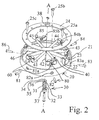
Fig. 2 is an exploded view of the assembly shown inFig. 1 ; -
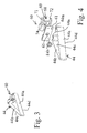
Fig. 3 is a perspective view of one of the V-shaped blades and clinch buckle utilized in the slicer shown inFigs. 1 and2 ; -
Fig. 4 is an exploded view of the V-shaped blade and clinch buckle shown inFig. 3 ; -
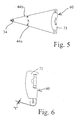
Fig. 5 is a top, plan view of the blade and clinch buckle shown inFig. 3 ; -
Fig. 6 is a plan view of the circle portion ofFig. 5 ; -
Fig. 7 is a perspective view of the V-shaped blade shown inFig. 3 , without the clinch buckle attached; -
Fig. 8 is a plan view of the blade shown in perspective inFig. 7 ; -
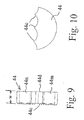
Fig. 9 is a side elevational view of the blade shown inFigs. 7 and 8 ; -
Fig. 10 is a closeup view of the serrated blade design used in the blade shown inFigs. 3 and7 ; -
Fig. 11 is a perspective view of the clinch plate, one component of the clinch buckle; -
Fig. 12 is an exploded view of the inner blade support hub shown inFig. 2 ; -
Fig. 13 is a perspective view of a second embodiment of the invention, wherein a plurality of three single blades is utilized; -
Fig. 14 is an exploded view of the embodiment shown inFig. 13 ; -
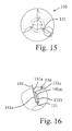
Fig. 15 is a plan view of the innerblade support hub 30 illustrating a "wedge-lock" design of the first blade support means; -
Fig. 16 is a closeup view of the circled portion ofFig. 15 ; -
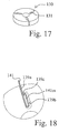
Fig. 17 is a perspective view of the inner blade support hub ofFig. 14 ; -
Fig. 18 is a closeup view of an alternate inner blade support means utilizing a "taper- lock" design; -
Fig. 19 is a perspective view of an assembled third embodiment of the invention utilizing a slotted hub design as an alternate first blade support means; -
Fig. 20 is an exploded view ofFig. 19 ; -
Fig. 21 is a perspective view of the inner support hub of the embodiment illustrated inFigs. 19 and 20 ; -
Fig. 22 is a plan view of the inner support hub shown inFig. 21 ; -
Fig. 23 is a section on the line 23-23 ofFig. 22 ; -
Fig. 24 is a plan view of the third embodiment of the invention shown inFigs. 19 and 20 ; -
Fig. 25 is a section on the line 25-25 ofFig. 24 ; -
Fig. 26 is a section on the line 26-26 ofFig. 24 ; and -
Fig. 27 is a reproduction of an image of apple cell walls stained with methylene blue. -
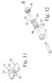
Figs. 1-11 illustrate a first embodiment ofapple slicer assembly 10 of the present invention.Fig. 1 is a perspective view of a fully assembledslicer 10 andFig. 2 is an exploded view. - It is to be understood that the
slicer assembly 10 is used in conjunction with an apple orienting, coring and slicing machine such as that shown inU.S. patent 4,007,676 , incorporated herein by reference as though set forth in full. In the interest of brevity, the orienting, conveying and coring aspects of the apparatus are not repeated here. Some updated versions of the apparatus (not pertinent to the slicer assembly) of the '676 patent are available from Atlas. Pacific Engineering Company of Pueblo, Colorado, and are not repeated here - As shown in
Figs. 1-11 ,wherein each reference numeral used refers to the same feature in each figure, an outerblade support ring 20 is provided, and aninner hub 30 is positioned preferably at the center of the circle formed byring 20. - A circular array of
blades 40 extends from innerblade support hub 30 radially outwardly toward cylindrical outerblade support ring 20. Each of the plurality ofblades 40 is a single continuous strip of resilient material preferably stainless steel, having a thickness "t" (seeFig. 6 ) less than 300 microns, preferably in the range of 180 to 220 microns. Blades thinner than 200 microns may be utilized with the clinch buckle blade supports of the present invention. Applicants believe that the blade thickness can be reduced to 100 microns, and possibly less than 100 microns, utilizing the present invention. Each blade has a width "w" (seeFig. 9 ) preferably of between 11.43 mm (0.45 inches) and 12.7 mm (0.50 inches). The width "w" may vary from 3.18 mm (0.125 inches) to 25.4 mm (1 inch) without limitation. Each of theblades 40 is flat, and each blade is aligned parallel with axis A-A (Fig. 2 ), which is parallel with the direction in which the apples are moved throughblade assembly 10, as is known in the art. - In the embodiment of
Figs. 1-11 , theassembly 10 includes six identical generally V-shaped blades 41-46. V-shapedblade 44 is shown in detail inFigs. 3-10 .Blade 44 has first andsecond legs Figs. 1-11 , angle x is 30°.Blade 44 has upper andlower edges upper edge 44c is preferably serrated and lower wedge is flat: - As shown best in
Figs. 4 ,7 and 8 , eachleg bent tab Bent tabs blade 44 with two bends, a 180° bend shown as 44t and 44u, and a 75° bend at thetips legs Tabs Figs. 1-11 : Thebent tabs leds - Clinch buckle means 60 is shown best in
Figs. 3-6 . Eachclinch buckle 60 includes a clinch plate 61 (Fig. 11 ), having aflat body 62, two 180° foldedears passageway 65 extending throughbody 62 Theears bent tabs Fig. 4 ). Clinch buckle means 60 also includesbuckle 68 having aflat body 69, top andbottom flanges 71 and 7-2 respectively, and-passageway 74 formed inbody 69. The purpose ofbuckle 68 is to help strengthen and rigidify the ultimate connection betweenclinch buckle 60 andblade 44. Whenclinch buckle 60 is assembled (seeFigs. 3, 5 and 6 ), the top andbottom flanges buckle 68 extend across the top and bottom ofclinch plate 61, and acrosstabs lower edges blade tabs flanges buckle 68. Two of the fillet welds 75 and 76 are shown inFig. 6 . Two welds are made on the bottom flange in the same location as elds 75, 76. Four similar fillet welds are made onbent tab 44n. The result is a robust, rigid connection for stiffening thelegs blade 44, and greatly enhancing the resistance ofblade 44 to flexing, bending and warping, especially after the blade is tensioned as described below. - Blade tensioning means 80 is shown partly in
Fig. 2 and partly inFig. 4 . Tensioning screws 81-86 extend throughpassageways 81a-86a (of which 81a-83a are visible inFig. 2 ) formed in outerblade support ring 20. Tensioning screws 81-86 extend through passageways 74 and 65 (Fig. 4 ) formed inbuckle 68 and clinchplate 61 and threadably engage nuts 81b 86b (only nuts 84b and 85b are visible inFig. 2 which are attached rigidly to (preferably by welding or 85b are visible inFig. 2 ), which are attached rigidly to (preferably by welding or cold forming) and carried by eachclinch buckle 60.Nut 84b is shown in exploded form in inFig. 4 . - It is significant to note that the outer
blade support ring 20 includes a smooth,circumferential band 21, abottom flange 22 to strengthenband 21, and an internal ledge orseat 23. Clinch buckles 60 seat againstbottom flange 22. Astop ring 24 is applied over clinch buckles 60 and held in its assembled position ofFig. 1 , in which it seats againstledge 23, the clinch buckles 60 are "captured" betweenbottom flange 22 andtop ring 24, i.e., the top andbottom flanges top ring 24 andbottom flange 22, respectively. The clinch buckles are thereby restrained and prevented from rotating, maximizing the rigidity of the connection between eachclinch buckle 60 and each blade 41-46. The rigidity of this connection is significantly greater than the connection achieved in U.S. prior art patent 4,007,676 by screws 968 and 969 described in that patent. Those screws (i.e. and 969) achieve tensioning of the prior art blade, but only provide limited resistance to bending and twisting of the prior art blades. - It is significant to note that although each clinch buckle means 60 is carried by
outer support ring 20 and is captured betweenbottom flange 22 andtop ring 24, the clinch buckles are free to slide radially inwardly and outwardly while the blades are being tensioned. - The inner
blade support hub 30 positioned preferably at the center ofring 20 is shown inFigs. 2 . and12 . The embodiment shown inFigs. 2 and12 includes a first blade support means comprising a plurality of pins 31-36. Pins-31-36 are securely anchored inlower hub 37 andupper hub 38. Pins 31-36 extend along the apex of each blade 41-46 and are in contact along the full width of both legs of each blade, as shown bypin 34 inFig. 5 . Pins 31-36 hold the apex of each blade, and the blade tensioning means 80 tensions the outer ends of each blade 41-46 against pins 31-36, respectively. Pins 31-36 extend across the entire width of each blade, and provide maximum resistance to bending; twisting or warping of the blades. -
Figs. 13-17 illustrate a second embodiment of the invention.Fig. 13 is a perspective view of a fully assembledslicer 110, andFig. 14 is an exploded view. The primary difference between the second embodiment shown inFigs. 13-17 and the first embodiment shown inFigs. 1-12 is that the second embodiment uses a plurality of three single blades 141-143 as opposed to the V-shaped "double" blades 41-46 of the first embodiment. The V-shaped "double" blades 41-46 of the first embodiment make two wedge shaped apple slices per blade, whereas the single blades 141-143 will create the same number of wedge shaped apple slices as there are blades. A secondary difference is the design of theinner hub 130 and the first blade support means described below. - The three blades 141-143 each have an
inner end 141a-143a connected toinner hub 130.Fig. 16 shows in greater detail theinner end 141 a ofblade 141. Theinner end 141a is formed with abent tab 141 m bent through 180° to fold back against theblade 141.Blades inner hub 130 has a series of blade wedge slots 131-133 formed therein to receive and support blades 141-143 and the bent tab on each blade.Wedge slot 131 includes a first slit orpassageway 131 a which slidably receivesblade 141 and an enlarged opening orpassageway 131 b which slidably receives thebent tab 141 m. Asblade 141 is tensioned, thebent tab 141 m bears against the taperedsurface 131 c ofslot 131.Tapered surface 131 c forms an obtuse angle withblade 141.Slot 131 and taperedsurface 131c extend across the entire width "w" ofblade 141 and provides rigid support against bending, twisting and warping ofblade 141. -
Slot 131 andbent tab 141 m comprise the "first blade support means" within the meaning of the claims. The clinch buckle means 160 is the same asclinch buckle 60 described above, and is not described in detail here for brevity. The three clinch buckles 160 used in the threesingle blade assembly 110 are all "captured" betweenlower flange 122 andtop ring 124 of cylindricalouter support ring 120, are thereby prevented from rotating to allow blades 141-143 to bend, twist or warp. -
Fig. 18 illustrates a "taper-lock" slot 139, which is a variation of the "wedge"slot 131 ofFig. 17 . The "taper-lock" slot 139 includes a first slit orpassageway 139a which slidably receivesblade 141, and anenlarged opening 139b which slidable receivesbent tab 141 m.Inclined surface 139c forms an acute angle formed by theinclined surface 139c (Fig. 18 ) withblade 141. The "taper-lock" slot 139 andbent tab 141m form the "first blade support means" within the meaning of the claims. -
Figs. 19-23 illustrate a third embodiment of the invention. Theslicer assembly 210 has only one significant difference fromassembly 10 shown inFigs. 1-11 . The difference is that theinner hub 230 is "slotted" with 12 slots 231-242 to receive the 12 legs of 6 V-shaped blades 241-246. Acircular recess 271 is formed ininner hub 230 to slidably receive the apex of each of V-shaped blades 241-246. The slottedhub 230 forms the "first blade support means" within the meaning of the claims. -
Figs. 24-26 illustrate plan and sectional views of thethird embodiment slicer 210.Fig 26 illustrates in cross-section how the tensioning means 280 drawsclinch buckle 260 away frominner hub 230 and towardouter support ring 220.Lower flange 222 andtop ring 224 are shown "capturing"clinch buckle 260 to support it and keep it from rotating.Fig. 25 also illustrates how the top andbottom flanges clinch buckle 260 are contacted by and captured bylower flange 222 andtop ring 224 ofouter support ring 220 to preventclinch buckle 260 from rotating, thereby maximizing the resistance ofblade 241 to bending, twisting and warping. - The blades 41-46, 141-143 and 241-246 are preferably serrated. The serrations may include various bevel designs as known in the art. The serrated nature of the blades helps minimize the number of cells ruptured during the slicing operation. It is significant to note that the clinch buckle means 60, 160 and 260 are designed to function with either serrated blades as shown or with flat, non-serrated blades.
-
Fig. 27 , as noted above at page 3, is a microscopic image of apple cells stained with methylene blue. - The foregoing description of the invention has been presented for purposes of illustration and description and is not intended to be exhaustive or to limit the invention to the precise form disclosed. Modifications and variations are possible in light of the above teaching. The embodiments were chosen and described to best explain the principles of the invention and its practical application to thereby enable others skilled in the art to best use the invention in various embodiments and with various modifications suited to the particular use contemplated. The scope of the invention is to be defined by the following claims.
Claims (15)
- An apparatus (10) for automatically slicing apples into a plurality of wedge shaped segments, the apparatus (10) comprising:a plurality of blades (40) extending, in a circular array, from an inner hub (30) to a cylindrical outer support ring (20);first blade support means (31-36, 131, 139, 230) carried by said inner hub (30) for supporting the inner end (141a-143a) of each of said blades (40) against bending, twisting and warping;characterised in that:each of said blades (40) has a thickness less than 300 microns, and each blade (40) has a bent tab (44m, 44n) at its outer end or ends; andthe apparatus (10) comprises:a plurality of clinch buckles (60) carried by said cylindrical outer support ring (20) for supporting the outer end or ends of each of said blades (40) against bending, twisting and warping, wherein each clinch buckle (60) is rigidly attached to a bent tab (44m, 44n) at an outer end of a blade (40); andblade tensioning means (80) for each blade (40) connected to each of said clinch buckles (60) and to said outer support ring (20) for adjustably tensioning each of said blades (40).
- The apparatus (10) of claim 1, further comprising means (222, 224) carried by said outer support ring (20) for capturing each clinch buckle (60) to prevent rotation of each of said clinch buckles (60).
- The apparatus (10) of claim 1 wherein each blade (40) has a thickness between 180 microns and 220 microns.
- The apparatus (10) of claim 1 wherein said blades (40) are serrated.
- The apparatus (10) of claim 1 wherein each of said clinch buckles (60) includes top (71) and bottom (72) flanges that extend across the upper (44c) and lower (44d) edges of said blades (40).
- The apparatus (10) of claim 5 wherein said top (71) and bottom (72) flanges are welded to the upper (44c) and lower (44d) edges of said serrated blades (40).
- The apparatus (10) of claim 6 wherein each of said clinch buckles (60) includes a clinch plate (61) which slidably engages said bent tabs (44m, 44n) at said outer end or ends of each of said blades (40).
- The apparatus (10) of claim 7 wherein each of said clinch plates (61) is welded to said upper (44c) and lower (44d) edges of said blades (40) and wherein each of said clinch plates (61) is welded to said top (71) and bottom (72) flanges.
- The apparatus (10) of claim 1 wherein said clinch buckle (60) is movable radially inwardly and outwardly by said tensioning means (80).
- The apparatus (10) of claim 1 wherein said first blade support means comprises a bent tab (141m) at said inner end (141a) of each of said blades (40) and a plurality of wedge-lock slots (131) formed in said inner hub (30).
- The apparatus (10) of claim 1 wherein said first blade support means comprises a bent tab (141m) at said inner end (141a) of each of said blades (40) and a plurality of taper-lock slots (139) formed in said inner hub (30).
- The apparatus (10) of claim 1 wherein each of said blades (40) is generally V-shaped, with each of said blades having first (44a) and second (44b) legs forming an apex angle x.
- The apparatus (10) of claim 12 wherein said bent tabs (44m, 44n) at the outer ends of each blade (40) are double folded tabs.
- The apparatus (10) of claim 12 wherein said first blade support means comprises a plurality of pins (31-36) carried by said inner hub (30).
- The apparatus (10) of claim 12 wherein said first blade support means comprises a slotted inner hub (230) for slidably receiving the apex of each of said V-shaped blades (40).
Priority Applications (1)
| Application Number | Priority Date | Filing Date | Title |
|---|---|---|---|
| PL06773691T PL1893390T3 (en) | 2005-06-21 | 2006-06-20 | Apparatus for slicing apples |
Applications Claiming Priority (2)
| Application Number | Priority Date | Filing Date | Title |
|---|---|---|---|
| US69255605P | 2005-06-21 | 2005-06-21 | |
| PCT/US2006/024147 WO2007002199A2 (en) | 2005-06-21 | 2006-06-20 | Apparatus for slicing apples |
Publications (3)
| Publication Number | Publication Date |
|---|---|
| EP1893390A2 EP1893390A2 (en) | 2008-03-05 |
| EP1893390A4 EP1893390A4 (en) | 2011-12-21 |
| EP1893390B1 true EP1893390B1 (en) | 2012-09-05 |
Family
ID=37595797
Family Applications (1)
| Application Number | Title | Priority Date | Filing Date |
|---|---|---|---|
| EP06773691A Active EP1893390B1 (en) | 2005-06-21 | 2006-06-20 | Apparatus for slicing apples |
Country Status (7)
| Country | Link |
|---|---|
| US (1) | US7610850B2 (en) |
| EP (1) | EP1893390B1 (en) |
| AU (1) | AU2006262208B2 (en) |
| BR (1) | BRPI0612514B1 (en) |
| NZ (1) | NZ563214A (en) |
| PL (1) | PL1893390T3 (en) |
| WO (1) | WO2007002199A2 (en) |
Families Citing this family (24)
| Publication number | Priority date | Publication date | Assignee | Title |
|---|---|---|---|---|
| USD649413S1 (en) | 2011-01-20 | 2011-11-29 | Columbia Insurance Company | Food wedger |
| USD650246S1 (en) | 2011-01-26 | 2011-12-13 | Columbia Insurance Company | Food slicer |
| USD648989S1 (en) | 2011-02-01 | 2011-11-22 | Columbia Insurance Company | Food wedger |
| USD650247S1 (en) | 2011-02-08 | 2011-12-13 | Columbia Insurance Company | Food slicer |
| AU2012276060B2 (en) * | 2011-06-27 | 2016-10-27 | Atlas Pacific Engineering Company | Slice blade assembly with non-welded replaceable blades |
| USD690170S1 (en) | 2011-08-03 | 2013-09-24 | Columbia Insurance Company | Food cutter |
| USD687267S1 (en) | 2011-08-03 | 2013-08-06 | Columbia Insurance Company | Food cutter |
| US9089987B2 (en) * | 2011-10-11 | 2015-07-28 | J.R. Simplot Company | Rotary knife fixture for cutting spiral, textured potato pieces |
| US9943978B2 (en) | 2011-10-11 | 2018-04-17 | J.R. Simplot Company | System for cutting spiral shaped pieces |
| USD716109S1 (en) * | 2013-08-06 | 2014-10-28 | Axis Sourcing Group, Inc. | Melon slicer |
| US20150273719A1 (en) | 2014-04-01 | 2015-10-01 | Mccain Foods Limited | Blade assembly and food cutting device incorporating the same |
| USD776496S1 (en) * | 2014-11-19 | 2017-01-17 | Tristar Products, Inc. | Melon slicer with base cover |
| US10160132B2 (en) * | 2015-09-11 | 2018-12-25 | J.R. Simplot Company | Flow-propelled rotary knife |
| CN109514634A (en) * | 2017-09-20 | 2019-03-26 | 贵港市瑞成科技有限公司 | A kind of automatic lemon slicing device |
| US11104025B2 (en) * | 2019-03-20 | 2021-08-31 | Mccain Foods Limited | Blade assembly for cutting food |
| USD896032S1 (en) * | 2019-06-13 | 2020-09-15 | Lamb Weston, Inc. | Cutter for food products |
| USD896031S1 (en) * | 2019-06-13 | 2020-09-15 | Lamb Weston, Inc. | Cutter for food products |
| CN110394836B (en) * | 2019-08-08 | 2021-02-12 | 东营海瑞宝新材料有限公司 | Method for processing hard polyurethane foam plastic pipeline heat-insulating layer |
| CN112971171B (en) * | 2019-12-17 | 2022-06-03 | 莒南和信食品有限公司 | Apple washs, coring and surely lamella all-in-one with anti-oxidation function |
| USD922143S1 (en) * | 2019-12-20 | 2021-06-15 | Lamb Weston, Inc. | Cutter for food products |
| USD922142S1 (en) * | 2019-12-20 | 2021-06-15 | Lamb Weston, Inc. | Cutter for food products |
| USD922822S1 (en) * | 2020-01-23 | 2021-06-22 | Lamb Weston, Inc. | Cut potato product |
| CA3249108A1 (en) * | 2022-04-29 | 2023-11-02 | Stumabo International N.V. | Cutting head assembly and knives for cutting food products into strips, and assembly method |
| USD1120219S1 (en) * | 2024-09-27 | 2026-03-24 | J.C. Ford Company | Valve assembly |
Family Cites Families (12)
| Publication number | Priority date | Publication date | Assignee | Title |
|---|---|---|---|---|
| US2496637A (en) * | 1948-01-19 | 1950-02-07 | Winnifred N Pease | Apple celling and slicing machine |
| US2703122A (en) * | 1952-05-31 | 1955-03-01 | F B Pease Company Inc | Apple celling and slicing machine |
| US2750976A (en) * | 1952-07-29 | 1956-06-19 | F B Pease Company Inc | Apple celling and slicing machine |
| US3696847A (en) * | 1970-06-15 | 1972-10-10 | Borden Inc | Apple slicer and celler |
| US4007676A (en) | 1974-01-09 | 1977-02-15 | Atlas Pacific Engineering Company | Segmenting knife for apple seed celling machine |
| US3948161A (en) * | 1974-09-18 | 1976-04-06 | Atlas Pacific Engineering Company | Seed celling machine |
| US4334557A (en) * | 1980-05-05 | 1982-06-15 | Yasenka Kathryn H | Canning utensil |
| ES2030020T3 (en) * | 1986-09-29 | 1992-10-16 | A. BORNER GmbH | RAW FOOD CUTTER. |
| US5520105A (en) * | 1994-05-06 | 1996-05-28 | Healy; Jack | Combination can crusher, juicer and slicer |
| US6047625A (en) | 1997-04-21 | 2000-04-11 | Mendenhall; George A. | Wedge cut blade apparatus |
| US6923104B2 (en) | 1997-05-09 | 2005-08-02 | Raleigh J. Jensen | Tensive cutting assembly |
| US6519815B2 (en) * | 1998-06-11 | 2003-02-18 | Bks Company, Llc | Band clamp |
-
2006
- 2006-06-20 PL PL06773691T patent/PL1893390T3/en unknown
- 2006-06-20 WO PCT/US2006/024147 patent/WO2007002199A2/en not_active Ceased
- 2006-06-20 AU AU2006262208A patent/AU2006262208B2/en active Active
- 2006-06-20 EP EP06773691A patent/EP1893390B1/en active Active
- 2006-06-20 NZ NZ563214A patent/NZ563214A/en unknown
- 2006-06-20 BR BRPI0612514-0A patent/BRPI0612514B1/en active IP Right Grant
- 2006-06-20 US US11/471,207 patent/US7610850B2/en active Active
Also Published As
| Publication number | Publication date |
|---|---|
| NZ563214A (en) | 2009-12-24 |
| EP1893390A4 (en) | 2011-12-21 |
| US20060283339A1 (en) | 2006-12-21 |
| AU2006262208B2 (en) | 2011-03-24 |
| EP1893390A2 (en) | 2008-03-05 |
| WO2007002199A2 (en) | 2007-01-04 |
| PL1893390T3 (en) | 2013-02-28 |
| BRPI0612514A2 (en) | 2010-11-30 |
| US7610850B2 (en) | 2009-11-03 |
| BRPI0612514B1 (en) | 2019-06-25 |
| WO2007002199A3 (en) | 2007-06-28 |
| AU2006262208A1 (en) | 2007-01-04 |
Similar Documents
| Publication | Publication Date | Title |
|---|---|---|
| AU2006262208B2 (en) | Apparatus for slicing apples | |
| US5765472A (en) | Fruit and vegetable hand slicer | |
| US8347511B2 (en) | Cutter assembly for concave tapered food product | |
| EP2632666B1 (en) | Apple wedger | |
| EP2900438B1 (en) | Tailored slicing | |
| US6814994B2 (en) | Method and device to obtain fresh fruit flesh slices | |
| DK2985125T3 (en) | ROTATING KNIFE UNIT TO CUT A FOOD PRODUCT IN SPIRAL SHEETS | |
| US20070215736A1 (en) | Cutter assembly with s-shaped blade | |
| EP3706969B1 (en) | Knife assemblies and cutting apparatuses comprising the same | |
| US3605840A (en) | Apparatus for comminuting comestibles | |
| JP2006523148A (en) | Product slicer | |
| EP2202036A1 (en) | Mandoline having adjustable infeed and outfeed decks | |
| US11104024B2 (en) | Produce pusher | |
| EP1584429B1 (en) | Cutting wheel for cutting a food product | |
| US318694A (en) | Bread-cutter | |
| EP2283735B1 (en) | Fleshy whole fruit pre-cut for division into pieces at the point of consumption and method and device for preparation thereof | |
| NL2003091C2 (en) | Piece of cheese cut from a block, such as a wheel, brick, or ball, and method of and apparatus for preparing the same. | |
| HK1085967A1 (en) | Cutting wheel for cutting a food product | |
| HK1085967B (en) | Cutting wheel for cutting a food product | |
| HK1123703A (en) | Mango slicer |
Legal Events
| Date | Code | Title | Description |
|---|---|---|---|
| PUAI | Public reference made under article 153(3) epc to a published international application that has entered the european phase |
Free format text: ORIGINAL CODE: 0009012 |
|
| 17P | Request for examination filed |
Effective date: 20071105 |
|
| AK | Designated contracting states |
Kind code of ref document: A2 Designated state(s): AT BE BG CH CY CZ DE DK EE ES FI FR GB GR HU IE IS IT LI LT LU LV MC NL PL PT RO SE SI SK TR |
|
| DAX | Request for extension of the european patent (deleted) | ||
| DAX | Request for extension of the european patent (deleted) | ||
| A4 | Supplementary search report drawn up and despatched |
Effective date: 20111123 |
|
| RIC1 | Information provided on ipc code assigned before grant |
Ipc: B26D 3/26 20060101ALI20111118BHEP Ipc: B26D 1/553 20060101ALI20111118BHEP Ipc: B26D 1/00 20060101AFI20111118BHEP |
|
| GRAP | Despatch of communication of intention to grant a patent |
Free format text: ORIGINAL CODE: EPIDOSNIGR1 |
|
| GRAS | Grant fee paid |
Free format text: ORIGINAL CODE: EPIDOSNIGR3 |
|
| GRAA | (expected) grant |
Free format text: ORIGINAL CODE: 0009210 |
|
| AK | Designated contracting states |
Kind code of ref document: B1 Designated state(s): AT BE BG CH CY CZ DE DK EE ES FI FR GB GR HU IE IS IT LI LT LU LV MC NL PL PT RO SE SI SK TR |
|
| REG | Reference to a national code |
Ref country code: GB Ref legal event code: FG4D |
|
| REG | Reference to a national code |
Ref country code: CH Ref legal event code: EP |
|
| REG | Reference to a national code |
Ref country code: AT Ref legal event code: REF Ref document number: 573872 Country of ref document: AT Kind code of ref document: T Effective date: 20120915 |
|
| REG | Reference to a national code |
Ref country code: IE Ref legal event code: FG4D |
|
| REG | Reference to a national code |
Ref country code: DE Ref legal event code: R096 Ref document number: 602006031848 Country of ref document: DE Effective date: 20121025 |
|
| REG | Reference to a national code |
Ref country code: NL Ref legal event code: T3 |
|
| REG | Reference to a national code |
Ref country code: AT Ref legal event code: MK05 Ref document number: 573872 Country of ref document: AT Kind code of ref document: T Effective date: 20120905 |
|
| PG25 | Lapsed in a contracting state [announced via postgrant information from national office to epo] |
Ref country code: CY Free format text: LAPSE BECAUSE OF FAILURE TO SUBMIT A TRANSLATION OF THE DESCRIPTION OR TO PAY THE FEE WITHIN THE PRESCRIBED TIME-LIMIT Effective date: 20120905 Ref country code: AT Free format text: LAPSE BECAUSE OF FAILURE TO SUBMIT A TRANSLATION OF THE DESCRIPTION OR TO PAY THE FEE WITHIN THE PRESCRIBED TIME-LIMIT Effective date: 20120905 Ref country code: FI Free format text: LAPSE BECAUSE OF FAILURE TO SUBMIT A TRANSLATION OF THE DESCRIPTION OR TO PAY THE FEE WITHIN THE PRESCRIBED TIME-LIMIT Effective date: 20120905 Ref country code: LT Free format text: LAPSE BECAUSE OF FAILURE TO SUBMIT A TRANSLATION OF THE DESCRIPTION OR TO PAY THE FEE WITHIN THE PRESCRIBED TIME-LIMIT Effective date: 20120905 |
|
| REG | Reference to a national code |
Ref country code: LT Ref legal event code: MG4D Effective date: 20120905 |
|
| PG25 | Lapsed in a contracting state [announced via postgrant information from national office to epo] |
Ref country code: SE Free format text: LAPSE BECAUSE OF FAILURE TO SUBMIT A TRANSLATION OF THE DESCRIPTION OR TO PAY THE FEE WITHIN THE PRESCRIBED TIME-LIMIT Effective date: 20120905 Ref country code: SI Free format text: LAPSE BECAUSE OF FAILURE TO SUBMIT A TRANSLATION OF THE DESCRIPTION OR TO PAY THE FEE WITHIN THE PRESCRIBED TIME-LIMIT Effective date: 20120905 Ref country code: GR Free format text: LAPSE BECAUSE OF FAILURE TO SUBMIT A TRANSLATION OF THE DESCRIPTION OR TO PAY THE FEE WITHIN THE PRESCRIBED TIME-LIMIT Effective date: 20121206 Ref country code: LV Free format text: LAPSE BECAUSE OF FAILURE TO SUBMIT A TRANSLATION OF THE DESCRIPTION OR TO PAY THE FEE WITHIN THE PRESCRIBED TIME-LIMIT Effective date: 20120905 |
|
| REG | Reference to a national code |
Ref country code: PL Ref legal event code: T3 |
|
| PG25 | Lapsed in a contracting state [announced via postgrant information from national office to epo] |
Ref country code: RO Free format text: LAPSE BECAUSE OF FAILURE TO SUBMIT A TRANSLATION OF THE DESCRIPTION OR TO PAY THE FEE WITHIN THE PRESCRIBED TIME-LIMIT Effective date: 20120905 Ref country code: ES Free format text: LAPSE BECAUSE OF FAILURE TO SUBMIT A TRANSLATION OF THE DESCRIPTION OR TO PAY THE FEE WITHIN THE PRESCRIBED TIME-LIMIT Effective date: 20121216 Ref country code: EE Free format text: LAPSE BECAUSE OF FAILURE TO SUBMIT A TRANSLATION OF THE DESCRIPTION OR TO PAY THE FEE WITHIN THE PRESCRIBED TIME-LIMIT Effective date: 20120905 Ref country code: IS Free format text: LAPSE BECAUSE OF FAILURE TO SUBMIT A TRANSLATION OF THE DESCRIPTION OR TO PAY THE FEE WITHIN THE PRESCRIBED TIME-LIMIT Effective date: 20130105 |
|
| PG25 | Lapsed in a contracting state [announced via postgrant information from national office to epo] |
Ref country code: PT Free format text: LAPSE BECAUSE OF FAILURE TO SUBMIT A TRANSLATION OF THE DESCRIPTION OR TO PAY THE FEE WITHIN THE PRESCRIBED TIME-LIMIT Effective date: 20130107 Ref country code: SK Free format text: LAPSE BECAUSE OF FAILURE TO SUBMIT A TRANSLATION OF THE DESCRIPTION OR TO PAY THE FEE WITHIN THE PRESCRIBED TIME-LIMIT Effective date: 20120905 |
|
| PLBE | No opposition filed within time limit |
Free format text: ORIGINAL CODE: 0009261 |
|
| STAA | Information on the status of an ep patent application or granted ep patent |
Free format text: STATUS: NO OPPOSITION FILED WITHIN TIME LIMIT |
|
| PG25 | Lapsed in a contracting state [announced via postgrant information from national office to epo] |
Ref country code: BG Free format text: LAPSE BECAUSE OF FAILURE TO SUBMIT A TRANSLATION OF THE DESCRIPTION OR TO PAY THE FEE WITHIN THE PRESCRIBED TIME-LIMIT Effective date: 20121205 Ref country code: DK Free format text: LAPSE BECAUSE OF FAILURE TO SUBMIT A TRANSLATION OF THE DESCRIPTION OR TO PAY THE FEE WITHIN THE PRESCRIBED TIME-LIMIT Effective date: 20120905 |
|
| 26N | No opposition filed |
Effective date: 20130606 |
|
| REG | Reference to a national code |
Ref country code: DE Ref legal event code: R097 Ref document number: 602006031848 Country of ref document: DE Effective date: 20130606 |
|
| PG25 | Lapsed in a contracting state [announced via postgrant information from national office to epo] |
Ref country code: MC Free format text: LAPSE BECAUSE OF FAILURE TO SUBMIT A TRANSLATION OF THE DESCRIPTION OR TO PAY THE FEE WITHIN THE PRESCRIBED TIME-LIMIT Effective date: 20120905 |
|
| REG | Reference to a national code |
Ref country code: IE Ref legal event code: MM4A |
|
| PG25 | Lapsed in a contracting state [announced via postgrant information from national office to epo] |
Ref country code: IE Free format text: LAPSE BECAUSE OF NON-PAYMENT OF DUE FEES Effective date: 20130620 |
|
| PG25 | Lapsed in a contracting state [announced via postgrant information from national office to epo] |
Ref country code: TR Free format text: LAPSE BECAUSE OF FAILURE TO SUBMIT A TRANSLATION OF THE DESCRIPTION OR TO PAY THE FEE WITHIN THE PRESCRIBED TIME-LIMIT Effective date: 20120905 |
|
| PG25 | Lapsed in a contracting state [announced via postgrant information from national office to epo] |
Ref country code: HU Free format text: LAPSE BECAUSE OF FAILURE TO SUBMIT A TRANSLATION OF THE DESCRIPTION OR TO PAY THE FEE WITHIN THE PRESCRIBED TIME-LIMIT; INVALID AB INITIO Effective date: 20060620 Ref country code: LU Free format text: LAPSE BECAUSE OF NON-PAYMENT OF DUE FEES Effective date: 20130620 |
|
| REG | Reference to a national code |
Ref country code: FR Ref legal event code: PLFP Year of fee payment: 11 |
|
| REG | Reference to a national code |
Ref country code: FR Ref legal event code: PLFP Year of fee payment: 12 |
|
| REG | Reference to a national code |
Ref country code: FR Ref legal event code: PLFP Year of fee payment: 13 |
|
| PGFP | Annual fee paid to national office [announced via postgrant information from national office to epo] |
Ref country code: NL Payment date: 20250516 Year of fee payment: 20 |
|
| PGFP | Annual fee paid to national office [announced via postgrant information from national office to epo] |
Ref country code: PL Payment date: 20250429 Year of fee payment: 20 Ref country code: DE Payment date: 20250429 Year of fee payment: 20 |
|
| PGFP | Annual fee paid to national office [announced via postgrant information from national office to epo] |
Ref country code: GB Payment date: 20250501 Year of fee payment: 20 |
|
| PGFP | Annual fee paid to national office [announced via postgrant information from national office to epo] |
Ref country code: BE Payment date: 20250516 Year of fee payment: 20 Ref country code: IT Payment date: 20250522 Year of fee payment: 20 |
|
| PGFP | Annual fee paid to national office [announced via postgrant information from national office to epo] |
Ref country code: FR Payment date: 20250508 Year of fee payment: 20 |
|
| PGFP | Annual fee paid to national office [announced via postgrant information from national office to epo] |
Ref country code: CZ Payment date: 20250602 Year of fee payment: 20 |
|
| PGFP | Annual fee paid to national office [announced via postgrant information from national office to epo] |
Ref country code: CH Payment date: 20250701 Year of fee payment: 20 |