EP0873828A2 - Cutting tool for cutting foodstuff - Google Patents
Cutting tool for cutting foodstuff Download PDFInfo
- Publication number
- EP0873828A2 EP0873828A2 EP98107115A EP98107115A EP0873828A2 EP 0873828 A2 EP0873828 A2 EP 0873828A2 EP 98107115 A EP98107115 A EP 98107115A EP 98107115 A EP98107115 A EP 98107115A EP 0873828 A2 EP0873828 A2 EP 0873828A2
- Authority
- EP
- European Patent Office
- Prior art keywords
- blade
- cutter
- engaged
- blades
- bore
- Prior art date
- Legal status (The legal status is an assumption and is not a legal conclusion. Google has not performed a legal analysis and makes no representation as to the accuracy of the status listed.)
- Granted
Links
- 239000007787 solid Substances 0.000 claims 1
- 235000013305 food Nutrition 0.000 abstract description 9
- 235000002595 Solanum tuberosum Nutrition 0.000 description 4
- 244000061456 Solanum tuberosum Species 0.000 description 4
- 235000012015 potatoes Nutrition 0.000 description 4
- 230000007246 mechanism Effects 0.000 description 3
- 230000000712 assembly Effects 0.000 description 2
- 238000000429 assembly Methods 0.000 description 2
- XLYOFNOQVPJJNP-UHFFFAOYSA-N water Substances O XLYOFNOQVPJJNP-UHFFFAOYSA-N 0.000 description 2
- 101100008050 Caenorhabditis elegans cut-6 gene Proteins 0.000 description 1
- 238000013459 approach Methods 0.000 description 1
- 238000005452 bending Methods 0.000 description 1
- 239000012267 brine Substances 0.000 description 1
- 235000012020 french fries Nutrition 0.000 description 1
- 238000000034 method Methods 0.000 description 1
- 230000002028 premature Effects 0.000 description 1
- HPALAKNZSZLMCH-UHFFFAOYSA-M sodium;chloride;hydrate Chemical compound O.[Na+].[Cl-] HPALAKNZSZLMCH-UHFFFAOYSA-M 0.000 description 1
- 239000000243 solution Substances 0.000 description 1
- 229910001220 stainless steel Inorganic materials 0.000 description 1
- 239000010935 stainless steel Substances 0.000 description 1
Images


Classifications
-
- B—PERFORMING OPERATIONS; TRANSPORTING
- B26—HAND CUTTING TOOLS; CUTTING; SEVERING
- B26D—CUTTING; DETAILS COMMON TO MACHINES FOR PERFORATING, PUNCHING, CUTTING-OUT, STAMPING-OUT OR SEVERING
- B26D3/00—Cutting work characterised by the nature of the cut made; Apparatus therefor
- B26D3/18—Cutting work characterised by the nature of the cut made; Apparatus therefor to obtain cubes or the like
- B26D3/185—Grid like cutters
-
- B—PERFORMING OPERATIONS; TRANSPORTING
- B26—HAND CUTTING TOOLS; CUTTING; SEVERING
- B26D—CUTTING; DETAILS COMMON TO MACHINES FOR PERFORATING, PUNCHING, CUTTING-OUT, STAMPING-OUT OR SEVERING
- B26D3/00—Cutting work characterised by the nature of the cut made; Apparatus therefor
- B26D3/24—Cutting work characterised by the nature of the cut made; Apparatus therefor to obtain segments other than slices, e.g. cutting pies
-
- B—PERFORMING OPERATIONS; TRANSPORTING
- B26—HAND CUTTING TOOLS; CUTTING; SEVERING
- B26D—CUTTING; DETAILS COMMON TO MACHINES FOR PERFORATING, PUNCHING, CUTTING-OUT, STAMPING-OUT OR SEVERING
- B26D7/00—Details of apparatus for cutting, cutting-out, stamping-out, punching, perforating, or severing by means other than cutting
- B26D7/26—Means for mounting or adjusting the cutting member; Means for adjusting the stroke of the cutting member
- B26D7/2614—Means for mounting the cutting member
-
- B—PERFORMING OPERATIONS; TRANSPORTING
- B26—HAND CUTTING TOOLS; CUTTING; SEVERING
- B26D—CUTTING; DETAILS COMMON TO MACHINES FOR PERFORATING, PUNCHING, CUTTING-OUT, STAMPING-OUT OR SEVERING
- B26D1/00—Cutting through work characterised by the nature or movement of the cutting member or particular materials not otherwise provided for; Apparatus or machines therefor; Cutting members therefor
- B26D1/0006—Cutting members therefor
- B26D2001/0033—Cutting members therefor assembled from multiple blades
-
- Y—GENERAL TAGGING OF NEW TECHNOLOGICAL DEVELOPMENTS; GENERAL TAGGING OF CROSS-SECTIONAL TECHNOLOGIES SPANNING OVER SEVERAL SECTIONS OF THE IPC; TECHNICAL SUBJECTS COVERED BY FORMER USPC CROSS-REFERENCE ART COLLECTIONS [XRACs] AND DIGESTS
- Y10—TECHNICAL SUBJECTS COVERED BY FORMER USPC
- Y10S—TECHNICAL SUBJECTS COVERED BY FORMER USPC CROSS-REFERENCE ART COLLECTIONS [XRACs] AND DIGESTS
- Y10S83/00—Cutting
- Y10S83/929—Particular nature of work or product
- Y10S83/932—Edible
-
- Y—GENERAL TAGGING OF NEW TECHNOLOGICAL DEVELOPMENTS; GENERAL TAGGING OF CROSS-SECTIONAL TECHNOLOGIES SPANNING OVER SEVERAL SECTIONS OF THE IPC; TECHNICAL SUBJECTS COVERED BY FORMER USPC CROSS-REFERENCE ART COLLECTIONS [XRACs] AND DIGESTS
- Y10—TECHNICAL SUBJECTS COVERED BY FORMER USPC
- Y10T—TECHNICAL SUBJECTS COVERED BY FORMER US CLASSIFICATION
- Y10T83/00—Cutting
- Y10T83/929—Tool or tool with support
- Y10T83/9493—Stationary cutter
-
- Y—GENERAL TAGGING OF NEW TECHNOLOGICAL DEVELOPMENTS; GENERAL TAGGING OF CROSS-SECTIONAL TECHNOLOGIES SPANNING OVER SEVERAL SECTIONS OF THE IPC; TECHNICAL SUBJECTS COVERED BY FORMER USPC CROSS-REFERENCE ART COLLECTIONS [XRACs] AND DIGESTS
- Y10—TECHNICAL SUBJECTS COVERED BY FORMER USPC
- Y10T—TECHNICAL SUBJECTS COVERED BY FORMER US CLASSIFICATION
- Y10T83/00—Cutting
- Y10T83/929—Tool or tool with support
- Y10T83/9493—Stationary cutter
- Y10T83/9495—Nonparallel cutting edges
Definitions
- This invention relates to a cutting apparatus for cutting food products into wedge-shaped portions, and in particular, a cutting apparatus which utilizes tensioned blades, and which can be configured for cutting food products into any number of wedge-shaped portions.
- Food products and produce such as potatoes are cut and shaped by being entrained in a process stream of water or brine and passed through a "hydroknife" blade assembly which typically includes multiple blades for cutting the produce into the desired shape and size.
- a hydroknife cutter assembly disclosed in US 5,095,794 is used for cutting potatoes into elongate, square cross-sectioned pieces for further processing into french fries.
- Another popular form for processed potatoes is wedge-shaped portions.
- the prior art includes some cutting assemblies for producing wedge-shaped portions, the prior art does not provide a wedge-cut cutter in which the blades are tensionable, which can be easily reconfigured to cut various numbers of wedge-cuts, and which are otherwise suitable for modern hydraulic cutting systems.
- the invention provides solutions to the needs unmet by the prior art.
- the invention is embodied in a cutter which includes a first body having a first axial bore, and a first elongate blade traversing the bore.
- the first blade has first and second end portions attached to respective first and second mounting surfaces milled into the first body.
- a first recess underlies a portion of the first blade, and a first blade tensioner urges a portion of the first blade toward the first recess.
- a cutter according to the invention may further include a second elongate blade traversing the bore at an angle to the first blade, the second blade having first and second end portions attached to respective third and fourth mounting surfaces.
- a second recess underlies a portion of the second blade, and a second blade tensioner urges a portion of the second blade toward the second recess.
- a blade tensioner according to the invention is embodied in a first bearing member which bears on the first blade, and a first biasing member bearing on the first bearing member.
- the bearing member is a cylindrical pin
- the biasing member is a screw or bolt
- the blade tensioners are adjustable to tension the blades to any of a plurality of selectable tensions.
- a cutter according to the invention may further include a second body similar to the first body, and stacked thereon to provide additional blades as required to achieve the desired number of cuts.
- the preferred embodiment includes mounting means for mounting the first and second bodies on an underlying surface.
- the mounting means includes a base member and means for removably attaching the first body to the base member.
- An end retainer is fitted atop the stacked body, and through bolts are used to secure the end retainer and stacked cutter bodies to the base plate.
- cutter assembly 10 is assembled from a bottom mounting plate 12, a lower 2-blade cutter section 14, an upper 2-blade cutter section 16, and an end retainer plate 18.
- the assembly is preferably made from stainless steel for food processing applications, although the invention is not limited thereto.
- Bolts 20a-d extend downwardly through end retainer plate 18 and cutter sections 14 and 16, and are threaded into holes in bottom mounting plate 12.
- Mounting plate 12 is provided for mounting cutter 10 in a food cutting system, such as a hydraulic food cutting apparatus (not shown).
- US 4,807,503 discloses an hydraulic cutting system in which potatoes are entrained in a water stream and passed through a blade assembly which is mounted in a conduit.
- This '503 patent teaches that it is advantageous to accelerate the food product as it approaches the blades.
- the same principle is applicable to this invention, although the cutter assembly of this invention can be used with other hydraulic cutting systems as well, and even with non-hydraulic cutting systems.
- the use of two cutter sections, each having two blades produces 8 equal wedge-shaped portions in a single pass.
- any even number of wedges can be produced by using different combinations of cutter sections and blades.
- a single cutter section can be used with one or two blades to produce two or four wedges.
- Three or more cutter sections, each with one or two blades, may be employed to cut 6 or 12 wedges, for example. Turning now to FIGS.
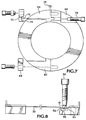
- cutter section is shown generally at 22, and may be generally described as a cylindrical collar having an axial through bore 23, and having recessed areas 24, 26 and 28 milled into its top surface 30.
- a blade 32 traverses axial bore 23 and is mounted at end 34 between shoulder 36 and blade clamp 38.
- Bolt 40 secures blade clamp 38 and blade end 34 to shoulder 36.
- Blade end 42 is likewise clamped by blade clamp 44 to shoulder 46 by bolt 48.
- Blade ends 34 and 42 may be notched or drilled to receive the respective bolts 40 and 48.
- shoulders 36 and 46 are offset from the transverse centerline of the axial bore 23 by one-half the thickness of blade 32.
- the ends of blade 32 are 0.008" thick, and shoulders 36 and 46 are offset 0.004" from the transverse centerline of bore 23. Owing to the relatively thin cross-section of blade 32, which can range from 0.004-0.012", the blade is placed in tension to ensure that it remains centered and does not flex when impacted by the food product.
- the present invention includes a blade tensioning mechanism wherein a tensioning force is applied to blade 32 by turning adjustment screw 50 inwardly against a roll pin 51, which in turn urges blade 32 around blade tension anvils 52 and 54 and into recess 56 of blade clamp 44. Screw 50 is locked in place by locknut 53 (FIG. 5).
- Blade tension roll pin 48 preferably extends the full width of the blade 32, and is of a sufficiently large radius to avoid unduly high bending stresses in the blade at the point of contact with the roll pin 48. Applicant has found that a 3/16" diameter roll pin is suitable for blades having a thickness of 0.004 to 0.012". Blade tension anvils 52 and 54 are also rounded in the preferred embodiment to minimize stress concentrations in blade 32 which if unchecked, could lead to premature failure of the blade. Although rounded roll pin and tension anvils extend blade life, the invention is not limited thereto, and other profiles could be employed for the roll pin and tension anvils without departing from the scope of the invention.
- the bottom surface of cutter section 22 includes a second blade 60, recessed milled areas 62, 64, 66, blade clamps 68 and 70, shoulders 72 and 74, and a blade tensioning assembly (roll pin 76 and adjustment screw 78) which are identical to those described with respect to the top surface (FIG. 7).
- blade 60 (FIG. 3) is rotated 90 degrees relative to blade 32 to provide four wedge portions per cutter assembly, and multiples of four wedges if multiple cutter assemblies are stacked. In other embodiments, different rotational offset between the upper and lower blades could be utilized.
- three wedges can be produced by stacking a cutter section having two blades which are offset by 120° instead of 90° atop a cutter section having a single blade which is oriented at 120° relative to each of the two lower blades.
Landscapes
- Life Sciences & Earth Sciences (AREA)
- Forests & Forestry (AREA)
- Engineering & Computer Science (AREA)
- Mechanical Engineering (AREA)
- Details Of Cutting Devices (AREA)
- Food-Manufacturing Devices (AREA)
- Crushing And Pulverization Processes (AREA)
Abstract
Description
Claims (9)
- Apparatus for cutting solid foodstuffs into slices of desired cross-sectional shape, comprising:a cutter body (10) having in it an axial bore (23);means (38, 40, 44, 48) for mounting at least one blade member (32, 60) so that it traverses the bore and has its ends engaged by clamps (38, 44);a transverse recess (56) in at least one of the clamping surfaces at one end of the path of the blade and underlying the blade path, anda blade tensioner (50, 51) extending transversely to the path of the blade and having its inner end movable in and out of the recess, whereby the intervening blade portion is able to be deflected out of its linear position to adjust the longitudinal tension in the blade.
- A cutter as claimed in claim 1, in which the cutter body has two axially-spaced means for mounting two blades (32, 60) so that their planes intersect at a desired angle to each other, and at the axis of the bore.
- A cutter as claimed in claim 1 or 2, in which two like cutters (10) are positioned coäxially in line with each other, the two bodies being angularly positioned relative to each other such that the planes of the blades intersect each other at desired angles.
- A cutter as claimed in claim 3, in which each cutter body has two blades mounted in it at 90° apart, and in which the blades in one cutter body are positioned at 45° to those of the other cutter body.
- A cutter as claimed in any preceding claim, in which one end of each blade is intended to be engaged by a clamp member (38) engaged by a screw (40) passing through an aperture in the blade; in which the other end of each blade is intended to be engaged by a second clamp member (44) engaged by a second screw (48), and in which the blade tensioner includes a cylindrical pin (51) intended to bear on the blade at a location between the second screw and the axial bore.
- A cutter as claimed in claim 5, in which the cylindrical pin (51) has its outer end engaged by a screw (50) in the body.
- A cutter as claimed in any preceding claim, in which the cutter body (10), or one of them, is adapted to be removably mounted on a base member (12).
- A cutter as claimed in claim 6, in which the other end face of the cutter body, or the remote end face of two contiguous and aligned cutter bodies, is engaged by a retainer plate (18) screwed to the base member.
- A cutter as claimed in any preceding claim, in which the mounting surfaces (36, 46) of the body, to which the blade is intended to be clamped, are spaced from a diametral plane by half the thickness of the blade, whereby the central plane of the blade lies on a diameter of the bore.
Applications Claiming Priority (2)
| Application Number | Priority Date | Filing Date | Title |
|---|---|---|---|
| US837616 | 1997-04-21 | ||
| US08/837,616 US6047625A (en) | 1997-04-21 | 1997-04-21 | Wedge cut blade apparatus |
Publications (3)
| Publication Number | Publication Date |
|---|---|
| EP0873828A2 true EP0873828A2 (en) | 1998-10-28 |
| EP0873828A3 EP0873828A3 (en) | 1999-10-27 |
| EP0873828B1 EP0873828B1 (en) | 2003-08-13 |
Family
ID=25274969
Family Applications (1)
| Application Number | Title | Priority Date | Filing Date |
|---|---|---|---|
| EP19980107115 Expired - Lifetime EP0873828B1 (en) | 1997-04-21 | 1998-04-19 | Cutting tool for cutting foodstuff |
Country Status (3)
| Country | Link |
|---|---|
| US (1) | US6047625A (en) |
| EP (1) | EP0873828B1 (en) |
| CA (1) | CA2232113C (en) |
Cited By (5)
| Publication number | Priority date | Publication date | Assignee | Title |
|---|---|---|---|---|
| NL1013937C2 (en) * | 1999-12-23 | 2001-06-26 | Aviko Bv | Device for cutting potatoes or other vegetables into slices or sticks. |
| WO2004091872A1 (en) * | 2003-04-02 | 2004-10-28 | Prime Slice, Llc | Produce slicer |
| WO2007002199A2 (en) | 2005-06-21 | 2007-01-04 | Atlas Pacific Engineering Company | Apparatus for slicing apples |
| US7513450B2 (en) | 2006-03-17 | 2009-04-07 | Centlgra Foods, Inc. | Cutter assembly with s-shaped blade |
| NL1038863C2 (en) * | 2011-06-07 | 2012-12-10 | Tummers Beheer B V | A SHARABLE CLIP CUTTING BLOCK FOR CUTTING CARBON-MADE PRODUCTS. |
Families Citing this family (14)
| Publication number | Priority date | Publication date | Assignee | Title |
|---|---|---|---|---|
| US6923104B2 (en) * | 1997-05-09 | 2005-08-02 | Raleigh J. Jensen | Tensive cutting assembly |
| US6725765B1 (en) | 2003-01-10 | 2004-04-27 | George A. Mendenhall | Cutter blade assembly for cutting vegetable products |
| EP2001595A4 (en) | 2006-03-17 | 2013-01-02 | Conagra Foods Inc | A concave tapered food product, method, and apparatus for producing such a product |
| US20090249930A1 (en) * | 2008-04-04 | 2009-10-08 | Progressive International Corporation | V-slicing blade |
| WO2009123651A1 (en) * | 2008-04-04 | 2009-10-08 | Progressive International Corporation | Chopper and slicer |
| USD585709S1 (en) | 2008-04-09 | 2009-02-03 | Progressive International Corporation | Combined chopper and slicer |
| USD582719S1 (en) | 2008-05-01 | 2008-12-16 | Progressive International Corporation | Multi-chopper |
| US9943978B2 (en) | 2011-10-11 | 2018-04-17 | J.R. Simplot Company | System for cutting spiral shaped pieces |
| US9089987B2 (en) * | 2011-10-11 | 2015-07-28 | J.R. Simplot Company | Rotary knife fixture for cutting spiral, textured potato pieces |
| FR3001909B1 (en) * | 2013-02-11 | 2015-02-27 | Mc Cain Foods Ltd | CUTTING BLOCK OF FOOD PRODUCTS IN "S" FRAGMENTS |
| US20150273719A1 (en) | 2014-04-01 | 2015-10-01 | Mccain Foods Limited | Blade assembly and food cutting device incorporating the same |
| US10843363B2 (en) * | 2017-11-10 | 2020-11-24 | Urschel Laboratories, Inc. | Knife assemblies and cutting apparatuses comprising the same |
| USD842025S1 (en) | 2018-02-22 | 2019-03-05 | Progressive International Corporation | Tower chopper |
| ES2817301B2 (en) * | 2020-06-10 | 2022-07-29 | Espeja Antonio Capdevila | PROCEDURE FOR PREPARING FRENCH FRIES AND FRENCH FRIES OBTAINED BY SAID PROCEDURE |
Family Cites Families (14)
| Publication number | Priority date | Publication date | Assignee | Title |
|---|---|---|---|---|
| US1879008A (en) * | 1930-03-31 | 1932-09-27 | Josiah Anstice & Co Inc | Vegetable slicing machine |
| GB398939A (en) * | 1932-04-22 | 1933-09-28 | Archie John Hobson | Improvements in or relating to apparatus for cutting vegetables |
| US2563237A (en) * | 1947-06-02 | 1951-08-07 | Grocoff William | Butter cutter |
| FR1238917A (en) * | 1959-07-10 | 1960-08-19 | Caves Et Des Producteurs Reuni | Machine for cutting cheese into sections in the shape of sectors |
| US3109470A (en) * | 1960-02-19 | 1963-11-05 | Joe R Urschel | Knife assembly |
| US3554253A (en) * | 1968-08-30 | 1971-01-12 | Paul Vasile | Combined slicing, dicing, coring and juicing apparatus |
| US4300429A (en) * | 1977-09-23 | 1981-11-17 | Amfac Foods, Inc. | Cutter element |
| US4573384A (en) * | 1984-08-01 | 1986-03-04 | Jones Frank W | Dicing device for sliced food articles |
| DE3544807C2 (en) * | 1985-12-18 | 1995-08-10 | Holac Maschbau Gmbh | Device for cutting food |
| US4911045A (en) * | 1987-06-08 | 1990-03-27 | Mendenhall George A | Decorative form hydraulic food product cutting blade assembly |
| DE4020827A1 (en) * | 1990-06-29 | 1992-01-02 | Wacker Chemitronic | TENSIONING SYSTEM FOR AN INSIDE HOLE SAW BLADE AND ITS USE IN SAWING BARS, ESPECIALLY MADE OF SEMICONDUCTOR MATERIAL, IN DISCS |
| US5197681A (en) * | 1990-12-03 | 1993-03-30 | Beltec International | Apparatus for safe high speed slicing/shaving of a food product |
| US5303687A (en) * | 1991-03-06 | 1994-04-19 | Silicon Technology Corporation | Blade mount for an inner diameter saw blade |
| US5343623A (en) * | 1992-05-11 | 1994-09-06 | Urschel Laboratories, Inc. | Knife assembly for cutting a food product |
-
1997
- 1997-04-21 US US08/837,616 patent/US6047625A/en not_active Expired - Fee Related
-
1998
- 1998-03-16 CA CA 2232113 patent/CA2232113C/en not_active Expired - Lifetime
- 1998-04-19 EP EP19980107115 patent/EP0873828B1/en not_active Expired - Lifetime
Cited By (10)
| Publication number | Priority date | Publication date | Assignee | Title |
|---|---|---|---|---|
| NL1013937C2 (en) * | 1999-12-23 | 2001-06-26 | Aviko Bv | Device for cutting potatoes or other vegetables into slices or sticks. |
| EP1110682A1 (en) * | 1999-12-23 | 2001-06-27 | Aviko B.V. | Device for cutting potatoes or other vegetables into slices or sticks |
| WO2004091872A1 (en) * | 2003-04-02 | 2004-10-28 | Prime Slice, Llc | Produce slicer |
| US6959636B2 (en) | 2003-04-02 | 2005-11-01 | Prime Slice, Llc | Produce slicer |
| GB2415359A (en) * | 2003-04-02 | 2005-12-28 | Prime Slice Llc | Produce slicer |
| GB2415359B (en) * | 2003-04-02 | 2006-07-26 | Prime Slice Llc | Produce slicer |
| WO2007002199A2 (en) | 2005-06-21 | 2007-01-04 | Atlas Pacific Engineering Company | Apparatus for slicing apples |
| EP1893390A4 (en) * | 2005-06-21 | 2011-12-21 | Atlas Pacifik Eng Co | APPARATUS FOR CUTTING APPLES IN SLICES |
| US7513450B2 (en) | 2006-03-17 | 2009-04-07 | Centlgra Foods, Inc. | Cutter assembly with s-shaped blade |
| NL1038863C2 (en) * | 2011-06-07 | 2012-12-10 | Tummers Beheer B V | A SHARABLE CLIP CUTTING BLOCK FOR CUTTING CARBON-MADE PRODUCTS. |
Also Published As
| Publication number | Publication date |
|---|---|
| US6047625A (en) | 2000-04-11 |
| EP0873828A3 (en) | 1999-10-27 |
| CA2232113C (en) | 2006-07-25 |
| EP0873828B1 (en) | 2003-08-13 |
| CA2232113A1 (en) | 1998-10-21 |
Similar Documents
| Publication | Publication Date | Title |
|---|---|---|
| EP0873828B1 (en) | Cutting tool for cutting foodstuff | |
| US5343623A (en) | Knife assembly for cutting a food product | |
| US6725765B1 (en) | Cutter blade assembly for cutting vegetable products | |
| CN1097498C (en) | Round bar blade and cutter head provided especially for same | |
| US4503893A (en) | Disc type wood chipper knife having positioning serrations and intermediate land therebetween | |
| US8534330B2 (en) | Knife and knife assembly for a planer side head | |
| CN1066383C (en) | Knife clamping system | |
| AU686093B2 (en) | Backsawn timber production from radially sawn wedges | |
| US6688351B2 (en) | Adjustable profiling head for a wood cutting apparatus | |
| US9278460B2 (en) | Apparatus for the cross-perforation or cross-cutting of continuous material webs | |
| US4498449A (en) | Precision tensioning device for ID saw blade | |
| CA2496660A1 (en) | Apparatus for planing an article of wood | |
| US20070158478A1 (en) | Method and apparatus for adjusting knife extension | |
| JPH10510489A (en) | Method and apparatus for retaining a cutting flitch | |
| EP0506683B1 (en) | Circular saw blade assembly | |
| US5655582A (en) | Modified quick change inserted edges anvil system for wood chippers | |
| US3294132A (en) | Circular chipping device | |
| US7584772B2 (en) | Method for clamping a knife in a disc chipper and a knife clamp for a knife assembly | |
| NZ528052A (en) | Wood cutting apparatus with discs each having teeth defining distinct cutting diameters | |
| CA2489896A1 (en) | Chipper knife | |
| US6923227B2 (en) | Canter chipper head | |
| FI87159C (en) | FOLLOWING ORGANIZATION FOR THE PURPOSE OF THE KNOWLEDGE I AND SKIVHUGG | |
| US7992604B1 (en) | Ripsaw stabilizing device | |
| SE463325B (en) | DEVICE FOR LINE MOVEMENT | |
| RU2773312C1 (en) | Replaceable knife insert |
Legal Events
| Date | Code | Title | Description |
|---|---|---|---|
| PUAI | Public reference made under article 153(3) epc to a published international application that has entered the european phase |
Free format text: ORIGINAL CODE: 0009012 |
|
| AK | Designated contracting states |
Kind code of ref document: A2 Designated state(s): BE GB NL |
|
| AX | Request for extension of the european patent |
Free format text: AL;LT;LV;MK;RO;SI |
|
| PUAL | Search report despatched |
Free format text: ORIGINAL CODE: 0009013 |
|
| AK | Designated contracting states |
Kind code of ref document: A3 Designated state(s): AT BE CH CY DE DK ES FI FR GB GR IE IT LI LU MC NL PT SE |
|
| AX | Request for extension of the european patent |
Free format text: AL;LT;LV;MK;RO;SI |
|
| 17P | Request for examination filed |
Effective date: 20000426 |
|
| AKX | Designation fees paid |
Free format text: BE GB NL |
|
| REG | Reference to a national code |
Ref country code: DE Ref legal event code: 8566 |
|
| 17Q | First examination report despatched |
Effective date: 20010716 |
|
| GRAH | Despatch of communication of intention to grant a patent |
Free format text: ORIGINAL CODE: EPIDOS IGRA |
|
| GRAH | Despatch of communication of intention to grant a patent |
Free format text: ORIGINAL CODE: EPIDOS IGRA |
|
| GRAA | (expected) grant |
Free format text: ORIGINAL CODE: 0009210 |
|
| AK | Designated contracting states |
Designated state(s): BE GB NL |
|
| REG | Reference to a national code |
Ref country code: GB Ref legal event code: FG4D |
|
| PLBE | No opposition filed within time limit |
Free format text: ORIGINAL CODE: 0009261 |
|
| STAA | Information on the status of an ep patent application or granted ep patent |
Free format text: STATUS: NO OPPOSITION FILED WITHIN TIME LIMIT |
|
| 26N | No opposition filed |
Effective date: 20040514 |
|
| REG | Reference to a national code |
Ref country code: GB Ref legal event code: 732E Free format text: REGISTERED BETWEEN 20120628 AND 20120704 |
|
| REG | Reference to a national code |
Ref country code: NL Ref legal event code: SD Effective date: 20121001 |
|
| PGFP | Annual fee paid to national office [announced via postgrant information from national office to epo] |
Ref country code: NL Payment date: 20150409 Year of fee payment: 18 |
|
| PGFP | Annual fee paid to national office [announced via postgrant information from national office to epo] |
Ref country code: GB Payment date: 20150415 Year of fee payment: 18 |
|
| PGFP | Annual fee paid to national office [announced via postgrant information from national office to epo] |
Ref country code: BE Payment date: 20150413 Year of fee payment: 18 |
|
| PG25 | Lapsed in a contracting state [announced via postgrant information from national office to epo] |
Ref country code: BE Free format text: LAPSE BECAUSE OF NON-PAYMENT OF DUE FEES Effective date: 20160430 |
|
| REG | Reference to a national code |
Ref country code: NL Ref legal event code: MM Effective date: 20160501 |
|
| GBPC | Gb: european patent ceased through non-payment of renewal fee |
Effective date: 20160419 |
|
| PG25 | Lapsed in a contracting state [announced via postgrant information from national office to epo] |
Ref country code: GB Free format text: LAPSE BECAUSE OF NON-PAYMENT OF DUE FEES Effective date: 20160419 Ref country code: NL Free format text: LAPSE BECAUSE OF NON-PAYMENT OF DUE FEES Effective date: 20160501 |