EP1892474A1 - Burner with protection element for ignition electrodes - Google Patents
Burner with protection element for ignition electrodes Download PDFInfo
- Publication number
- EP1892474A1 EP1892474A1 EP06017534A EP06017534A EP1892474A1 EP 1892474 A1 EP1892474 A1 EP 1892474A1 EP 06017534 A EP06017534 A EP 06017534A EP 06017534 A EP06017534 A EP 06017534A EP 1892474 A1 EP1892474 A1 EP 1892474A1
- Authority
- EP
- European Patent Office
- Prior art keywords
- burner
- ignition
- protective element
- ignition electrode
- electrode
- Prior art date
- Legal status (The legal status is an assumption and is not a legal conclusion. Google has not performed a legal analysis and makes no representation as to the accuracy of the status listed.)
- Withdrawn
Links
- 230000001681 protective effect Effects 0.000 claims abstract description 26
- 239000000463 material Substances 0.000 claims description 4
- 238000005452 bending Methods 0.000 abstract description 4
- 238000009434 installation Methods 0.000 abstract description 4
- 230000035939 shock Effects 0.000 abstract description 3
- 239000000446 fuel Substances 0.000 description 10
- VNWKTOKETHGBQD-UHFFFAOYSA-N methane Chemical compound C VNWKTOKETHGBQD-UHFFFAOYSA-N 0.000 description 6
- 238000002485 combustion reaction Methods 0.000 description 5
- 238000011161 development Methods 0.000 description 4
- 230000018109 developmental process Effects 0.000 description 4
- 239000007789 gas Substances 0.000 description 4
- 241001156002 Anthonomus pomorum Species 0.000 description 3
- 239000003345 natural gas Substances 0.000 description 3
- 229910000831 Steel Inorganic materials 0.000 description 2
- 230000001419 dependent effect Effects 0.000 description 2
- 238000010304 firing Methods 0.000 description 2
- 239000000203 mixture Substances 0.000 description 2
- 239000010959 steel Substances 0.000 description 2
- 230000002411 adverse Effects 0.000 description 1
- 239000002737 fuel gas Substances 0.000 description 1
- 239000000295 fuel oil Substances 0.000 description 1
- 239000007788 liquid Substances 0.000 description 1
- 239000002184 metal Substances 0.000 description 1
- 239000003208 petroleum Substances 0.000 description 1
- 238000005476 soldering Methods 0.000 description 1
- 238000010792 warming Methods 0.000 description 1
- 238000003466 welding Methods 0.000 description 1
Images


Classifications
-
- F—MECHANICAL ENGINEERING; LIGHTING; HEATING; WEAPONS; BLASTING
- F23—COMBUSTION APPARATUS; COMBUSTION PROCESSES
- F23Q—IGNITION; EXTINGUISHING-DEVICES
- F23Q9/00—Pilot flame igniters
-
- F—MECHANICAL ENGINEERING; LIGHTING; HEATING; WEAPONS; BLASTING
- F23—COMBUSTION APPARATUS; COMBUSTION PROCESSES
- F23Q—IGNITION; EXTINGUISHING-DEVICES
- F23Q3/00—Igniters using electrically-produced sparks
- F23Q3/006—Details
-
- F—MECHANICAL ENGINEERING; LIGHTING; HEATING; WEAPONS; BLASTING
- F23—COMBUSTION APPARATUS; COMBUSTION PROCESSES
- F23Q—IGNITION; EXTINGUISHING-DEVICES
- F23Q7/00—Incandescent ignition; Igniters using electrically-produced heat, e.g. lighters for cigarettes; Electrically-heated glowing plugs
- F23Q7/22—Details
- F23Q7/24—Safety arrangements
Definitions
- the invention relates to a burner with an igniter and at least one ignition electrode, in particular one for installation in a burner of a gas turbine.
- a designed as a pilot burner torch with a detonator and igniter leading ignition electrodes is, for example, in EP 0 193 838 B1 described.
- the detonator has the task of igniting the fuel.
- the ignition electrodes are attached to the outside of the pilot burner and run parallel to its longitudinal axis.
- the fuel supply is located inside the pilot burner and ends in fuel outlet openings.
- the ignition electrodes end in the region of the fuel outlet openings and ignite the fuel emerging there by means of a spark.
- the spark is generated by an ignition voltage between two ignition electrodes and is active during the entire ignition duration.
- Damage to or bending of one or both of the ignition electrodes mounted on the pilot burner during transport or installation may adversely affect the performance of the ignition electrodes. Damage or bending may therefore necessitate replacement of the ignition electrodes.
- the replacement of the ignition electrodes may also be necessary if one of the electrodes is so bent that, instead of between the electrode tips between an electrode line and another metallic component to the electric flashover and therefore the gas mixture can not be ignited.
- the invention has for its object to provide a burner with at least one ignition electrode available, in which the above problem does not occur or only to a reduced extent.
- the burner can be designed in particular as a pilot burner.
- the solution of the problem is that the burner is equipped with at least one extending on its outer side ignition electrode, said electrode is associated with a protective element which projects beyond the outside of the burner and beyond the ignition electrode.
- the advantage of the solution according to the invention is therefore that the ignition electrodes are protected and therefore damage during transport or when installing and removing the ignition electrodes can be avoided.
- the protective element is connected to the outside of the burner, so that the necessary stability is ensured.
- the protective element surrounds the ignition electrodes, wherein the ignition electrode is at least partially covered lengthwise, so that the at least one ignition electrode is optimally protected.
- the protective member may be U-shaped and fixed with the open side and the outside of the burner, so that the ignition electrode are protected from three sides to the outside.
- the protective element can completely enclose the electrodes at least in the front region near the electrode tips.
- the protective element may be formed by at least one rib, so that a better accessibility of the ignition electrodes is ensured.
- the rib can run parallel to the ignition electrode. There may also be at least one rib on each side of the ignition electrode.
- the protective element is made of a rigid and impact-resistant material, so that a deformation of the protective element, which could lead to a deformation of the internal ignition electrodes, is avoided.
- a further advantageous development is that the distance between the protective element and the ignition electrode is at least so great that when an ignition voltage applied to the ignition electrode no flashover between the protective element and the ignition electrode, so that a current flashover between the ignition electrode and the protective element can be reliably avoided ,
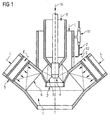
- the burner assembly shown in FIG 1 belongs to a gas turbine plant, the preferred field of application of the invention.
- the burner arrangement is, however, also suitable for gas-fired furnaces of boilers.
- the burner arrangement consists of at least one first burner 2 (not shown in FIG 1, see FIGS 2, 3), which serves as a pilot burner, and a second burner 1, which serves as a main burner and in the middle of the first burner 2 is used coaxially.
- the first burner 2 has a burner head 4 with a swirl blading 3 and can be operated with natural gas E and / or fuel oil H as fuel.
- the head 4 of the first burner 2 is coaxial with respect to the burner axis, surrounded by an air supply channel 6, which serves to supply the main portion of the combustion air L to a combustion zone (not shown) formed downstream of the burner head 4.
- the annular gap, the pressurized combustion air L is supplied from a compressor of the gas turbine plant. The hot fuel gases flow into the turbine blading.
- the main burner serving as the second burner 1 is supplemented by the first, serving as a pilot burner burner 2, i. In natural gas mode, it is possible to switch from pilot burner to main burner mode with its lower NOx values after starting up and warming up.
- the first burner 2 serves to stabilize the flame.
- the second burner comprises nozzle tubes 5 and an air supply channel 6.
- the nozzle tubes are connected to a fuel supply system (not shown) and serve to mix petroleum, natural gas or other gaseous or liquid fuel with the supplied combustion air L.
- the air supply channel 6 passes the combustion air L possibly with admixed fuel to the flame area.
- the ignition of the first burner 2 supplied air-fuel mixture via a rod or tubular electrode assembly with two ignition electrodes 7.
- the ignition electrodes 7 are mainly parallel to the axis of the first burner 2. In the region of the support plate 9 through which the ignition electrodes however, the distance of the ignition electrodes 7 from the outer wall of the first burner is significantly greater. The distance of the ignition electrodes 7 from each other is greater in the region of the support plate than in the region of the outer wall of the first burner 2.
- the ignition electrodes are fastened with connecting pieces 11 on the outside of the first burner 2.
- a burner 2 is shown as an exemplary embodiment of a burner according to the invention, on the outer wall of which two ignition electrodes 7 extending in the longitudinal direction of the burner 2 are mounted.
- the burner 2 can in particular serve as the first burner in the burner arrangement described with reference to FIG.
- the ignition electrodes of the burner 2 are covered by a protective element 8, which is formed in the present example as a U-shaped bent sheet 8.
- the legs of the sheet 8 each have an angled region in which they are attached to the outer wall of the burner 2.
- the attachment 10 is advantageously carried out by means of suitable detachable connecting elements, for example screws, so that, if necessary, access to the ignition electrodes 7 is possible.
- detachable connecting elements for example screws
- non-detachable connections are also possible instead of the detachable connection, for example welded connections.
- the U-shaped metal sheet extends at least over the front part of the ignition electrodes 7, ie the part which lies close to the electrode tips 12.
- the sheet 8 should be made of an impact resistant and rigid material such as e.g. Be made of steel.
- the distance of the sheet 8 from the ignition electrodes 7 should be at least so great that when a firing voltage applied to the ignition electrodes 7 no flashover between the fender 8 and the ignition electrodes 7 takes place.
- the concrete value for the distance depends on the dielectric strength of the medium between the electrodes 7 and the protective plate 8 as well as the geometry of the ignition electrodes and the temperature prevailing when the ignition voltage is applied. In the present embodiment with air as the medium, a safety distance of at least 5 mm should be maintained if the ignition voltage is 5 kV.
- FIG. 3 shows an ignition electrode 7 mounted in the burner 2 with two ignition electrodes 7 mounted on its outer wall.
- This burner 2 can also be used, in particular, as the first burner in the burner arrangement described with reference to FIG.
- the longitudinal ribs 8 project from the surface of the burner 2 via the ignition electrodes 7, so that the ignition electrodes 7 are protected from shocks.
- the ribs 8 are fixedly connected to the wall of the burner 2.
- the attachment 10 can be made for example by welding or soldering. Although detachable connections between the longitudinal ribs 8 and the burner 2, for example by means of screws, are also possible, non-detachable connections are completely sufficient since the arrangement does not substantially restrict access to the ignition electrodes 7 and the ribs 8 are therefore accessible the electrodes 7 need not be removed.
- the ribs 8 should be made of a shock-resistant and rigid material such as steel.
- the distance of the ribs from the ignition electrodes 7 should be at least at a starting voltage of 5 kV 5 mm so that no flashover between a firing electrode and a rib can take place.
Landscapes
- Engineering & Computer Science (AREA)
- Chemical & Material Sciences (AREA)
- Combustion & Propulsion (AREA)
- Mechanical Engineering (AREA)
- General Engineering & Computer Science (AREA)
- Gas Burners (AREA)
- Spark Plugs (AREA)
- Investigating, Analyzing Materials By Fluorescence Or Luminescence (AREA)
- Measuring Oxygen Concentration In Cells (AREA)
Abstract
Die Erfindung betrifft einen Brenner 2 mit einem Zünder und einer Zündelektrode 7 für den Einbau in einen Hauptbrenner 1 einer Gasturbine. Durch Beschädigung oder Verbiegen der am Brenner 2 angebrachten Zündelektrode 7 beim Transport oder Ein- bzw. Ausbau kann es während des Betriebes zur Verbiegung oder zum Bruch der Zündelektrode 7 kommen. Erfindungsgemäß wird die Zündelektrode 7 durch ein Schutzelement 8 gegen Beschädigungen geschützt. Das führt dazu, dass bei einem Stoß das Schutzelement 8 und nicht die Zündelektrode 7 belastet wird.

Description
Die Erfindung betrifft einen Brenner mit einem Zünder und wenigstens einer Zündelektrode, insbesondere einen solchen für den Einbau in einen Brenner einer Gasturbine.The invention relates to a burner with an igniter and at least one ignition electrode, in particular one for installation in a burner of a gas turbine.
Ein als Pilotbrenner ausgebildeter Brenner mit einem Zünder und zum Zünder führenden Zündelektroden ist beispielsweise in
Beschädigungen oder Verbiegung einer oder beider am Pilotbrenner angebrachten Zündelektroden beim Transport oder Einbau können die Funktionstüchtigkeit der Zündelektroden negativ beeinflussen. Beschädigungen oder Verbiegung können daher den Austausch der Zündelektroden notwendig werden lassen.Damage to or bending of one or both of the ignition electrodes mounted on the pilot burner during transport or installation may adversely affect the performance of the ignition electrodes. Damage or bending may therefore necessitate replacement of the ignition electrodes.
Der Austausch der Zündelektroden kann auch notwendig werden, wenn eine der Elektroden so sehr verbogen ist, dass es anstatt zwischen den Elektrodenspitzen zwischen einer Elektrodenleitung und einem anderen metallischen Bauteil zum Stromüberschlag kommt und daher das Gasgemisch nicht gezündet werden kann.The replacement of the ignition electrodes may also be necessary if one of the electrodes is so bent that, instead of between the electrode tips between an electrode line and another metallic component to the electric flashover and therefore the gas mixture can not be ignited.
Der Erfindung liegt die Aufgabe zugrunde, einen Brenner mit wenigstens einer Zündelektrode zur Verfügung zu stellen, bei dem die oben genannte Problematik nicht oder nur in reduziertem Maße auftritt.The invention has for its object to provide a burner with at least one ignition electrode available, in which the above problem does not occur or only to a reduced extent.
Diese Aufgabe wird durch einen Brenner mit den Merkmalen des Anspruchs 1 gelöst. Der Brenner kann insbesondere als Pilotbrenner ausgebildet sein.This object is achieved by a burner having the features of claim 1. The burner can be designed in particular as a pilot burner.
Erfindungsgemäß besteht die Lösung der Aufgabe darin, dass der Brenner mit wenigstens einer an seiner Außenseite verlaufenden Zündelektrode ausgerüstet ist, wobei dieser Elektrode ein Schutzelement zugeordnet ist, welches über die Außenseite des Brenners und über die Zündelektrode hinaus vorsteht.According to the invention the solution of the problem is that the burner is equipped with at least one extending on its outer side ignition electrode, said electrode is associated with a protective element which projects beyond the outside of the burner and beyond the ignition electrode.
Der Vorteil der erfindungsgemäßen Lösung liegt also darin, dass die Zündelektroden geschützt sind und daher Beschädigungen beim Transport bzw. beim Ein- und Ausbau der Zündelektroden vermieden werden können.The advantage of the solution according to the invention is therefore that the ignition electrodes are protected and therefore damage during transport or when installing and removing the ignition electrodes can be avoided.
Vorteilhafte Weiterbildungen sind in den abhängigen Ansprüchen angegeben.Advantageous developments are specified in the dependent claims.
Bei einer vorteilhaften Weiterbildung der Erfindung ist das Schutzelement mit der Außenseite des Brenners verbunden, so dass die nötige Stabilität gewährleistet ist.In an advantageous embodiment of the invention, the protective element is connected to the outside of the burner, so that the necessary stability is ensured.
Eine andere vorteilhafte Weiterbildung besteht darin, dass das Schutzelement die Zündelektroden umgibt, wobei die Zündelektrode zumindest teilweise der Länge nach abgedeckt wird, so dass die wenigstens eine Zündelektrode optimal geschützt ist.Another advantageous development is that the protective element surrounds the ignition electrodes, wherein the ignition electrode is at least partially covered lengthwise, so that the at least one ignition electrode is optimally protected.
Außerdem kann das Schutzelement U-förmig ausgebildet und mit der offenen Seite and der Außenseite des Brenners befestigt sein, so dass die Zündelektrode von drei Seiten nach außen hin geschützt werden. Das Schutzelement kann die Elektroden zumindest im vorderen Bereich nahe den Elektrodenspitzen vollständig umschließen.In addition, the protective member may be U-shaped and fixed with the open side and the outside of the burner, so that the ignition electrode are protected from three sides to the outside. The protective element can completely enclose the electrodes at least in the front region near the electrode tips.
Alternativ kann das Schutzelement durch wenigstens eine Rippe gebildet sein, so dass eine bessere Zugänglichkeit der Zündelektroden gewährleistet ist. Die Rippe kann parallel zur Zündelektrode verlaufen. Es kann sich auch auf beiden Seiten der Zündelektrode jeweils mindestens eine Rippe befinden.Alternatively, the protective element may be formed by at least one rib, so that a better accessibility of the ignition electrodes is ensured. The rib can run parallel to the ignition electrode. There may also be at least one rib on each side of the ignition electrode.
Vorzugsweise wird das Schutzelement aus einem biegesteifen und stoßfesten Material hergestellt, so dass eine Verformung des Schutzelements, die zu einer Verformung der innen liegenden Zündelektroden führen könnte, vermieden wird.Preferably, the protective element is made of a rigid and impact-resistant material, so that a deformation of the protective element, which could lead to a deformation of the internal ignition electrodes, is avoided.
Eine weitere vorteilhafte Weiterbildung besteht darin, der Abstand zwischen dem Schutzelement und der Zündelektrode mindestens so groß ist dass bei Anliegen einer Zündspannung an der Zündelektrode kein Überschlag zwischen dem Schutzelement und der Zündelektrode erfolgt, damit ein Stromüberschlag zwischen der Zündelektrode und dem Schutzelement zuverlässig vermieden werden kann.A further advantageous development is that the distance between the protective element and the ignition electrode is at least so great that when an ignition voltage applied to the ignition electrode no flashover between the protective element and the ignition electrode, so that a current flashover between the ignition electrode and the protective element can be reliably avoided ,
Weitere Merkmale, Eigenschaften und Vorteile der Erfindung ergeben sich aus der nachfolgenden Beschreibung von Ausführungsbeispielen unter Bezugnahme auf die beiliegenden Figuren. Es zeigt:
- FIG 1
- einen Brenner mit einer Zündelektrode,
- FIG 2
- einen Brenner mit Zündelektroden und einem Schutzelement, das einen U-förmigen Querschnitt aufweist und die Zündelektroden im vorderen Bereich umgibt,
- FIG 3
- einen Brenner mit Zündelektroden und einem Schutzelement, welches aus Rippen gebildet ist und parallel zu den Zündelektroden verläuft.
- FIG. 1
- a burner with an ignition electrode,
- FIG. 2
- a burner with ignition electrodes and a protective element which has a U-shaped cross-section and surrounds the ignition electrodes in the front region,
- FIG. 3
- a burner with ignition electrodes and a protective element, which is formed from ribs and runs parallel to the ignition electrodes.
Die in FIG 1 dargestellte Brenneranordnung gehört zu einer Gasturbinenanlage, dem bevorzugten Anwendungsgebiet der Erfindung. Die Brenneranordnung ist indes auch für gasbefeuerte Feuerungsanlagen von Kesseln geeignet.The burner assembly shown in FIG 1 belongs to a gas turbine plant, the preferred field of application of the invention. The burner arrangement is, however, also suitable for gas-fired furnaces of boilers.
Die Brenneranordnung besteht aus wenigstens einem an einer Trägerplatte (in FIG 1 nicht dargestellt; s. FIG 2, 3) befestigten ersten Brenner 2, der als Pilotbrenner dient, und einem zweiten Brenner 1, der als Hauptbrenner dient und in dessen Mitte der erste Brenner 2 koaxial eingesetzt ist. Der erste Brenner 2 weist einen Brennerkopf 4 mit einer Drallbeschaufelung 3 auf und kann mit Erdgas E und/oder Heizöl H als Brennstoff betrieben werden. Der Kopf 4 des ersten Brenners 2 ist koaxial, bezogen auf die Brennerachse, umgeben von einem Luftzufuhrkanal 6, welcher der Zufuhr des Hauptanteils der Verbrennungsluft L zu einer stromab des Brennerkopfes 4 ausgebildeten Verbrennungszone (nicht dargestellt) dient. Dem Ringspalt wird die unter Druck stehende Verbrennungsluft L von einem Kompressor der Gasturbinenanlage zugeführt. Die heißen Brenngase strömen in die Turbinenbeschaufelung.The burner arrangement consists of at least one first burner 2 (not shown in FIG 1, see FIGS 2, 3), which serves as a pilot burner, and a second burner 1, which serves as a main burner and in the middle of the
Der als Hauptbrenner dienende zweite Brenner 1 wird durch den ersten, als Pilotbrenner dienenden Brenner 2 ergänzt, d.h. bei Erdgasbetrieb kann nach dem Anfahren und Anwärmen vom Pilotbrenner- auf den Hauptbrennerbetrieb mit seinen geringeren NOx-Werten umgeschaltet werden. Der erste Brenner 2 dient dabei zur Stabilisierung der Flamme.The main burner serving as the second burner 1 is supplemented by the first, serving as a
Der zweite Brenner umfasst Düsenrohre 5 und einen Luftzufuhrkanal 6. Die Düsenrohre sind an ein Brennstoffzuleitungssystem angeschlossen (nicht dargestellt) und dienen zur Vermischung von Erdöl, Erdgas oder einem anderen gasförmigen oder flüssigen Brennstoff mit der zugeführten Verbrennungsluft L. Der Luftzufuhrkanal 6 leitet die Verbrennungsluft L ggf. mit beigemischtem Brennstoff dem Flammenbereich zu.The second burner comprises
Die Zündung des dem ersten Brenner 2 zugeführten Luft-Brennstoff-Gemisches erfolgt über eine stab- oder rohrförmige Elektrodenanordnung mit zwei Zündelektroden 7. Die Zündelektroden 7 verlaufen hauptsächlich parallel zur Achse des ersten Brenners 2. Im Bereich der Trägerplatte 9, durch die die Zündelektroden 7 hindurchgeführt sind, ist der Abstand der Zündelektroden 7 von der Außenwand des ersten Brenners jedoch deutlich größer. Auch der Abstand der Zündelektroden 7 untereinander ist im Bereich der Trägerplatte größer als im Bereich der Außenwand des ersten Brenners 2. Die Zündelektroden sind mit Verbindungsstücken 11 auf der Außenseite des ersten Brenners 2 befestigt.The ignition of the
In Figur 2 ist als Ausführungsbeispiel für einen erfindungsgemäßen Brenner ein Brenner 2 dargestellt, an dessen Außenwand zwei in Längsrichtung des Brenners 2 verlaufende Zündelektroden 7 angebracht sind. Der Brenner 2 kann insbesondere als erster Brenner in der mit Bezug auf FIG 1 beschriebenen Brenneranordnung dienen.In FIG. 2, a
Die Zündelektroden des Brenners 2 sind durch ein Schutzelement 8 abgedeckt, das im vorliegenden Beispiel als U-förmig gebogenes Blech 8 ausgebildet ist. Die Schenkel des Bleches 8 weisen jeweils einen abgewinkelten Bereich auf, in dem sie an der Außenwand des Brenners 2 befestigt sind. Die Befestigung 10 erfolgt vorteilhafterweise durch geeignete lösbare Verbindungselemente, z.B. Schrauben, damit im Bedarfsfall ein Zugang zu den Zündelektroden 7 möglich ist. Statt der lösbaren Verbindung sind grundsätzlich auch nicht lösbare Verbindungen möglich, bspw. Schweißverbindungen. Das U-förmige Blech erstreckt sich zumindest über den vorderen Teil der Zündelektroden 7, d.h. den Teil, der nahe den Elektrodenspitzen 12 liegt.The ignition electrodes of the
Das Blech 8 sollte aus einem stoßfesten und biegesteifen Werkstoff wie z.B. Stahl gefertigt sein. Der Abstand des Bleches 8 von den Zündelektroden 7 sollte mindestens so groß sein, dass bei Anliegen einer Zündspannung an den Zündelektroden 7 kein Überschlag zwischen dem Schutzblech 8 und den Zündelektroden 7 erfolgt. Der konkrete Wert für den Abstand hängt von der Durchschlagsfestigkeit des Mediums zwischen den Elektroden 7 und dem Schutzblech 8 sowie der Geometrie der Zündelektroden und der bei Anliegen der Zündspannung herrschenden Temperatur ab. Im vorliegenden Ausführungsbeispiel mit Luft als Medium sollte ein Sicherheitsabstand von mindestens 5 mm eingehalten werden, wenn die Zündspannung 5 kV beträgt.The
Figur 3 zeigt einen im Brenner 2 mit zwei an seiner Außenwand angebrachten Zündelektroden 7. Auch dieser Brenner 2 kann insbesondere als erster Brenner in der mit Bezug auf FIG 1 beschriebenen Brenneranordnung dienen.FIG. 3 shows an
Rechts und links von den Zündelektroden 7 des in FIG 3 dargestellten Brenners 2 verläuft jeweils eine Längsrippe 8. Die Längsrippen 8 stehen von der Oberfläche des Brenners 2 aus über die Zündelektroden 7 vor, so dass die Zündelektroden 7 vor Stößen geschützt sind. Die Rippen 8 sind fest mit der Wand des Brenners 2 verbunden. Die Befestigung 10 kann beispielsweise durch Schweißen oder Löten erfolgen. Lösbare Verbindungen zwischen den Längsrippen 8 und dem Brenner 2, bspw. mittels Schrauben, sind zwar auch möglich, aber nicht lösbare Verbindungen sind völlig ausrechend, da die Anordnung den Zugang zu den Zündelektroden 7 nicht wesentlich einschränkt und die Rippen 8 daher für den Zugang zu den Elektroden 7 nicht abgenommen werden müssen.Right and left of the
Wie das Blech des ersten Ausführungsbeispiels sollten die Rippen 8 aus einem stoßfesten und biegesteifen Werkstoff wie z.B. Stahl gefertigt sein. Der Abstand der Rippen von den Zündelektroden 7 sollte bei einer Zündspannung von 5 kV mindestens 5 mm betragen, damit kein Stromüberschlag zwischen einer Zündelektrode und einer Rippe stattfinden kann.Like the sheet of the first embodiment, the
Abschließend sei angemerkt, dass sämtlichen Merkmalen, die in den Anmeldungsunterlagen und insbesondere in den abhängigen Ansprüchen genannt sind, trotz des vorgenommenen formalen Rückbezuges auf einen oder mehrere bestimmte Ansprüche, auch einzeln oder in beliebiger Kombination eigenständiger Schutz zukommen soll.Finally, it should be noted that all the features that are mentioned in the application documents and in particular in the dependent claims, despite the formal reference to one or more specific claims, even individually or in any combination should receive independent protection.
Claims (11)
dadurch gekennzeichnet, dass das Schutzelement (8) mit der Außenseite des Brenners (2) verbunden ist.Burner (2) according to claim 1,
characterized in that the protective element (8) is connected to the outside of the burner (2).
dadurch gekennzeichnet, dass das Schutzelement (8) die Zündelektrode (7) umgibt, wobei die Zündelektrode (7) zumindest teilweise der Länge nach abgedeckt wird.Burner (2) according to claims 1 and 2,
characterized in that the protective element (8) surrounds the ignition electrode (7), wherein the ignition electrode (7) is at least partially covered lengthwise.
dadurch gekennzeichnet, dass das Schutzelement (8) im Querschnitt U-förmig ausgebildet und mit der offenen Seite an der Außenseite des Brenners (2) befestigt ist.Burner (2) according to claim 3,
characterized in that the protective element (8) is U-shaped in cross-section and fixed with the open side on the outside of the burner (2).
dadurch gekennzeichnet, dass das Schutzelement (8) die Zündelelektrode (7) zumindest im vorderen Bereich nahe den Elektrodenspitzen umschließt.Burner (2) according to claim 4,
characterized in that the protective element (8) encloses the Zündel electrode (7) at least in the front region near the electrode tips.
dadurch gekennzeichnet, dass das Schutzelement (8) wenigstens eine Rippe umfasst.Burner (2) according to claim 1 or 2,
characterized in that the protective element (8) comprises at least one rib.
dadurch gekennzeichnet, dass sich die Rippe (8) parallel zur Zündelektrode (7) erstreckt.Burner (2) according to claim 6,
characterized in that the rib (8) extends parallel to the ignition electrode (7).
dadurch gekennzeichnet, dass sich auf beiden Seiten der Zündelektrode jeweils mindestens eine Rippe befindet.Burner (2) according to claim 6 or 7,
characterized in that there is at least one rib each on both sides of the ignition electrode.
dadurch gekennzeichnet, dass das Schutzelement (8) aus einem biegesteifen und stoßfesten Material ist.Burner (2) according to one of the preceding claims,
characterized in that the protective element (8) is made of a rigid and impact-resistant material.
dadurch gekennzeichnet, dass der Abstand zwischen dem Schutzelement (8) und der Zündelektrode (7) mindestens so groß ist dass bei Anliegen einer Zündspannung an der Zündelektrode (7) kein Überschlag zwischen dem Schutzelement (8) und der Zündelektrode (7) erfolgt.Burner (2) according to one of the preceding claims,
characterized in that the distance between the protective element (8) and the ignition electrode (7) is at least so great that upon application of an ignition voltage to the ignition electrode (7) no flashover between the protective element (8) and the ignition electrode (7).
gekennzeichnet durch seine Ausgestaltung als Pilotbrenner für eine Brenneranordnung.Burner (2) according to one of the preceding claims,
characterized by its design as a pilot burner for a burner assembly.
Priority Applications (13)
| Application Number | Priority Date | Filing Date | Title |
|---|---|---|---|
| EP06017534A EP1892474A1 (en) | 2006-08-23 | 2006-08-23 | Burner with protection element for ignition electrodes |
| EP07788421A EP2054669B1 (en) | 2006-08-23 | 2007-08-14 | Burner with a protective element for ignition electrodes |
| KR1020097005879A KR101391212B1 (en) | 2006-08-23 | 2007-08-14 | Burner with a protective element for ignition electrodes |
| JP2009525023A JP2010501767A (en) | 2006-08-23 | 2007-08-14 | Burner with protection element for ignition electrode |
| DE502007003342T DE502007003342D1 (en) | 2006-08-23 | 2007-08-14 | BURNER WITH A PROTECTIVE ELEMENT FOR IGNITION ELECTRODES |
| ES07788421T ES2342500T3 (en) | 2006-08-23 | 2007-08-14 | BURNER WITH A PROTECTIVE ELEMENT FOR IGNITION ELECTRODE. |
| AT07788421T ATE462933T1 (en) | 2006-08-23 | 2007-08-14 | BURNER WITH A PROTECTIVE ELEMENT FOR IGNITION ELECTRODES |
| CN2007800289382A CN101501401B (en) | 2006-08-23 | 2007-08-14 | Burner with ignition electrode protection |
| PCT/EP2007/058411 WO2008022948A1 (en) | 2006-08-23 | 2007-08-14 | Burner with a protective element for ignition electrodes |
| PT07788421T PT2054669E (en) | 2006-08-23 | 2007-08-14 | Burner with a protective element for ignition electrodes |
| RU2009110175/06A RU2439433C2 (en) | 2006-08-23 | 2007-08-14 | Burner of gas turbine, and gas turbine |
| US12/310,284 US8327616B2 (en) | 2006-08-23 | 2007-08-14 | Burner having a protective element for ignition electrodes |
| JP2011281519A JP5484436B2 (en) | 2006-08-23 | 2011-12-22 | Burner with protection element for ignition electrode |
Applications Claiming Priority (1)
| Application Number | Priority Date | Filing Date | Title |
|---|---|---|---|
| EP06017534A EP1892474A1 (en) | 2006-08-23 | 2006-08-23 | Burner with protection element for ignition electrodes |
Publications (1)
| Publication Number | Publication Date |
|---|---|
| EP1892474A1 true EP1892474A1 (en) | 2008-02-27 |
Family
ID=37606836
Family Applications (2)
| Application Number | Title | Priority Date | Filing Date |
|---|---|---|---|
| EP06017534A Withdrawn EP1892474A1 (en) | 2006-08-23 | 2006-08-23 | Burner with protection element for ignition electrodes |
| EP07788421A Active EP2054669B1 (en) | 2006-08-23 | 2007-08-14 | Burner with a protective element for ignition electrodes |
Family Applications After (1)
| Application Number | Title | Priority Date | Filing Date |
|---|---|---|---|
| EP07788421A Active EP2054669B1 (en) | 2006-08-23 | 2007-08-14 | Burner with a protective element for ignition electrodes |
Country Status (11)
| Country | Link |
|---|---|
| US (1) | US8327616B2 (en) |
| EP (2) | EP1892474A1 (en) |
| JP (2) | JP2010501767A (en) |
| KR (1) | KR101391212B1 (en) |
| CN (1) | CN101501401B (en) |
| AT (1) | ATE462933T1 (en) |
| DE (1) | DE502007003342D1 (en) |
| ES (1) | ES2342500T3 (en) |
| PT (1) | PT2054669E (en) |
| RU (1) | RU2439433C2 (en) |
| WO (1) | WO2008022948A1 (en) |
Cited By (1)
| Publication number | Priority date | Publication date | Assignee | Title |
|---|---|---|---|---|
| US8564276B2 (en) | 2008-11-21 | 2013-10-22 | Siemens Aktiengesellschaft | Method and measurement device for determining a condition of an electric igniter of a gas turbine burner and an ignition device for a gas turbine burner |
Families Citing this family (5)
| Publication number | Priority date | Publication date | Assignee | Title |
|---|---|---|---|---|
| EP2012060A1 (en) * | 2007-07-03 | 2009-01-07 | Siemens Aktiengesellschaft | Three-point anchorage of ignition electrodes of a burner |
| GB2489963B (en) * | 2011-04-13 | 2015-11-04 | Rolls Royce Plc | Fuel injector arrangement having an igniter |
| RU2493489C2 (en) * | 2011-07-28 | 2013-09-20 | Общество с ограниченной ответственностью "Энерго Эстейт" | Method of safe burner operation in wide range of loads |
| CN109595587B (en) * | 2017-09-30 | 2024-01-16 | 宁波方太厨具有限公司 | Ignition needle and gas burner using same |
| CN109838816B (en) * | 2017-11-29 | 2023-11-17 | 宁波方太厨具有限公司 | Gas stove ignition needle and combustor provided with same |
Citations (7)
| Publication number | Priority date | Publication date | Assignee | Title |
|---|---|---|---|---|
| US2850084A (en) * | 1954-03-19 | 1958-09-02 | Robertshaw Fulton Coutrols Com | Electric ignition device for gaseous fuel |
| US3823345A (en) * | 1971-01-19 | 1974-07-09 | J Willson | Electric igniter construction |
| US4029936A (en) * | 1975-01-13 | 1977-06-14 | The Tappan Company | Igniter assembly |
| EP0193838A2 (en) * | 1985-03-04 | 1986-09-10 | Siemens Aktiengesellschaft | Burner disposition for combustion installations, especially for combustion chambers of gas turbine installations, and method for its operation |
| US5856651A (en) * | 1998-04-06 | 1999-01-05 | Surface Igniter Corporation | Shield for a hot surface ignitor and method for fabricating a shield |
| US5860804A (en) * | 1997-10-30 | 1999-01-19 | Societe En Commandite Gaz Metropolitain | Baffle ignitor assembly |
| US6777650B1 (en) * | 2000-02-04 | 2004-08-17 | Saint-Gobtain Industrial Ceramics, Inc. | Igniter shields |
Family Cites Families (15)
| Publication number | Priority date | Publication date | Assignee | Title |
|---|---|---|---|---|
| FR1592091A (en) | 1968-02-27 | 1970-05-11 | ||
| JPS5130904U (en) * | 1974-08-28 | 1976-03-05 | ||
| JPS5130904A (en) * | 1974-09-09 | 1976-03-16 | Seiko Koki Kk | DOKIMOOTAATONISHOSARERUDENJIKUDOSOCHI |
| JPS5257106U (en) * | 1975-10-23 | 1977-04-25 | ||
| JPS5257106A (en) * | 1975-11-06 | 1977-05-11 | Shiyouji Nanba | Stable high concentrated liquid alminium alkolate composition with easy handling |
| US4149373A (en) * | 1977-08-29 | 1979-04-17 | United Technologies Corporation | Combustion chamber stress reducing means |
| DE3536198A1 (en) * | 1985-10-10 | 1987-04-16 | Webasto Werk Baier Kg W | IGNITION SPARKER FOR FUEL-OPERATED HEATER |
| EP0228091A3 (en) * | 1986-01-03 | 1988-08-24 | A/S Kongsberg Väpenfabrikk | Axially compact gas turbine burner and method for cooling same |
| US4903476A (en) | 1988-12-27 | 1990-02-27 | General Electric Company | Gas turbine igniter with ball-joint support |
| US5393224A (en) * | 1993-12-02 | 1995-02-28 | American Standard Inc. | Ignitor assembly for power burner furnace |
| US5465571A (en) * | 1993-12-21 | 1995-11-14 | United Technologies Corporation | Fuel nozzle attachment in gas turbine combustors |
| US5802859A (en) * | 1996-12-16 | 1998-09-08 | Hudson Technologies, Inc. | Apparatus for recovering and analyzing volatile refrigerants |
| JP3875395B2 (en) * | 1998-03-24 | 2007-01-31 | 財団法人石油産業活性化センター | Catalytic combustion equipment |
| CN100510538C (en) * | 2003-08-22 | 2009-07-08 | 株式会社能率 | Ignition unit |
| DE202004006644U1 (en) | 2004-04-27 | 2004-08-26 | Buderus Heiztechnik Gmbh | electrode |
-
2006
- 2006-08-23 EP EP06017534A patent/EP1892474A1/en not_active Withdrawn
-
2007
- 2007-08-14 PT PT07788421T patent/PT2054669E/en unknown
- 2007-08-14 JP JP2009525023A patent/JP2010501767A/en active Pending
- 2007-08-14 WO PCT/EP2007/058411 patent/WO2008022948A1/en not_active Ceased
- 2007-08-14 US US12/310,284 patent/US8327616B2/en active Active
- 2007-08-14 AT AT07788421T patent/ATE462933T1/en active
- 2007-08-14 RU RU2009110175/06A patent/RU2439433C2/en active
- 2007-08-14 CN CN2007800289382A patent/CN101501401B/en active Active
- 2007-08-14 KR KR1020097005879A patent/KR101391212B1/en active Active
- 2007-08-14 DE DE502007003342T patent/DE502007003342D1/en active Active
- 2007-08-14 EP EP07788421A patent/EP2054669B1/en active Active
- 2007-08-14 ES ES07788421T patent/ES2342500T3/en active Active
-
2011
- 2011-12-22 JP JP2011281519A patent/JP5484436B2/en active Active
Patent Citations (7)
| Publication number | Priority date | Publication date | Assignee | Title |
|---|---|---|---|---|
| US2850084A (en) * | 1954-03-19 | 1958-09-02 | Robertshaw Fulton Coutrols Com | Electric ignition device for gaseous fuel |
| US3823345A (en) * | 1971-01-19 | 1974-07-09 | J Willson | Electric igniter construction |
| US4029936A (en) * | 1975-01-13 | 1977-06-14 | The Tappan Company | Igniter assembly |
| EP0193838A2 (en) * | 1985-03-04 | 1986-09-10 | Siemens Aktiengesellschaft | Burner disposition for combustion installations, especially for combustion chambers of gas turbine installations, and method for its operation |
| US5860804A (en) * | 1997-10-30 | 1999-01-19 | Societe En Commandite Gaz Metropolitain | Baffle ignitor assembly |
| US5856651A (en) * | 1998-04-06 | 1999-01-05 | Surface Igniter Corporation | Shield for a hot surface ignitor and method for fabricating a shield |
| US6777650B1 (en) * | 2000-02-04 | 2004-08-17 | Saint-Gobtain Industrial Ceramics, Inc. | Igniter shields |
Cited By (1)
| Publication number | Priority date | Publication date | Assignee | Title |
|---|---|---|---|---|
| US8564276B2 (en) | 2008-11-21 | 2013-10-22 | Siemens Aktiengesellschaft | Method and measurement device for determining a condition of an electric igniter of a gas turbine burner and an ignition device for a gas turbine burner |
Also Published As
| Publication number | Publication date |
|---|---|
| DE502007003342D1 (en) | 2010-05-12 |
| JP2010501767A (en) | 2010-01-21 |
| JP5484436B2 (en) | 2014-05-07 |
| EP2054669B1 (en) | 2010-03-31 |
| US8327616B2 (en) | 2012-12-11 |
| WO2008022948A1 (en) | 2008-02-28 |
| KR20090048508A (en) | 2009-05-13 |
| ES2342500T3 (en) | 2010-07-07 |
| ATE462933T1 (en) | 2010-04-15 |
| RU2009110175A (en) | 2010-09-27 |
| JP2012107624A (en) | 2012-06-07 |
| PT2054669E (en) | 2010-04-21 |
| EP2054669A1 (en) | 2009-05-06 |
| CN101501401A (en) | 2009-08-05 |
| US20110120077A1 (en) | 2011-05-26 |
| KR101391212B1 (en) | 2014-05-02 |
| CN101501401B (en) | 2011-01-26 |
| RU2439433C2 (en) | 2012-01-10 |
Similar Documents
| Publication | Publication Date | Title |
|---|---|---|
| DE102011055241B4 (en) | Apparatus and method for igniting a combustor assembly | |
| EP2054669B1 (en) | Burner with a protective element for ignition electrodes | |
| DE102010045175A1 (en) | Igniter for igniting a fuel-air mixture by means of an RF corona discharge and engine with such detonators | |
| DE1201122B (en) | Flame ignition device for the combustion chamber of a gas turbine system | |
| CH697703B1 (en) | Fuel nozzle assembly. | |
| EP1754002B1 (en) | Staged premix burner with an injector for liquid fuel | |
| DE102004041272B4 (en) | Hybrid burner lance | |
| DE602004000485T2 (en) | afterburning | |
| EP2092245B1 (en) | Burner for a gas turbine with fuel supply heat shield | |
| EP2409086B1 (en) | Burner assembly for a gas turbine | |
| EP2037173B1 (en) | Burner head and method for one-step combustion of fuel in a combustion zone separated from the burner head | |
| DE3238206A1 (en) | IGNITION DEVICE FOR CARBON DUST BURNERS | |
| DE102009013664A1 (en) | System for introducing fuel into the exhaust system of a motor vehicle and fuel evaporator therefor | |
| DE811056C (en) | Combustion chamber arrangement for liquid fuels for internal combustion turbines | |
| EP2422136B1 (en) | Pre-mix burner | |
| DE4446609A1 (en) | Fuel feed device for oil- or gas-fired burner for gas turbine | |
| DE102004030790B4 (en) | Spark plug with ignition cable | |
| DE882775C (en) | Ignition device for gas turbine engines | |
| CH688525A5 (en) | Gas burner | |
| AT395761B (en) | BURNER | |
| DE19741508A1 (en) | Mixer for oil or gas burner | |
| EP2048440B1 (en) | Burner | |
| DE102007025761B4 (en) | flame tube | |
| DE29901832U1 (en) | Flame monitoring and ignition device | |
| DE3911924A1 (en) | Nozzle, in particular with piezoelectric ignition, and ignition module with such a nozzle |
Legal Events
| Date | Code | Title | Description |
|---|---|---|---|
| PUAI | Public reference made under article 153(3) epc to a published international application that has entered the european phase |
Free format text: ORIGINAL CODE: 0009012 |
|
| AK | Designated contracting states |
Kind code of ref document: A1 Designated state(s): AT BE BG CH CY CZ DE DK EE ES FI FR GB GR HU IE IS IT LI LT LU LV MC NL PL PT RO SE SI SK TR |
|
| AX | Request for extension of the european patent |
Extension state: AL BA HR MK YU |
|
| 17P | Request for examination filed |
Effective date: 20080411 |
|
| 17Q | First examination report despatched |
Effective date: 20080520 |
|
| AKX | Designation fees paid |
Designated state(s): AT BE BG CH CY CZ DE DK EE ES FI FR GB GR HU IE IS IT LI LT LU LV MC NL PL PT RO SE SI SK TR |
|
| STAA | Information on the status of an ep patent application or granted ep patent |
Free format text: STATUS: THE APPLICATION IS DEEMED TO BE WITHDRAWN |
|
| 18D | Application deemed to be withdrawn |
Effective date: 20101110 |