EP1892466A1 - Halter für eine Lichtquelle - Google Patents
Halter für eine Lichtquelle Download PDFInfo
- Publication number
- EP1892466A1 EP1892466A1 EP06380230A EP06380230A EP1892466A1 EP 1892466 A1 EP1892466 A1 EP 1892466A1 EP 06380230 A EP06380230 A EP 06380230A EP 06380230 A EP06380230 A EP 06380230A EP 1892466 A1 EP1892466 A1 EP 1892466A1
- Authority
- EP
- European Patent Office
- Prior art keywords
- reflector
- lamp holder
- area
- light
- european patent
- Prior art date
- Legal status (The legal status is an assumption and is not a legal conclusion. Google has not performed a legal analysis and makes no representation as to the accuracy of the status listed.)
- Withdrawn
Links
- 239000011521 glass Substances 0.000 claims description 6
- 238000000034 method Methods 0.000 claims description 5
- 239000004417 polycarbonate Substances 0.000 claims description 3
- 229920000515 polycarbonate Polymers 0.000 claims description 3
- 239000005357 flat glass Substances 0.000 claims 1
- 238000010586 diagram Methods 0.000 description 1
- 230000004048 modification Effects 0.000 description 1
- 238000012986 modification Methods 0.000 description 1
- 239000004033 plastic Substances 0.000 description 1
- 230000003068 static effect Effects 0.000 description 1
Images

Classifications
-
- F—MECHANICAL ENGINEERING; LIGHTING; HEATING; WEAPONS; BLASTING
- F21—LIGHTING
- F21V—FUNCTIONAL FEATURES OR DETAILS OF LIGHTING DEVICES OR SYSTEMS THEREOF; STRUCTURAL COMBINATIONS OF LIGHTING DEVICES WITH OTHER ARTICLES, NOT OTHERWISE PROVIDED FOR
- F21V19/00—Fastening of light sources or lamp holders
- F21V19/02—Fastening of light sources or lamp holders with provision for adjustment, e.g. for focusing
Definitions
- the invention refers to improvements to the purpose of the main Patent No. 6.380.159.1, by adding a mechanism to the lamp holder for the light, which allows the light generated by it to be adjusted quickly and efficiently, so that the operator assembling the light can direct the light produced by the lamp to the required area without using special tools. In this way and at the same time, small faults in the alignment of other parts of the equipment, such as the arm holding the light and the vertical nature of the column holding the aforementioned light can be rectified.
- the main European Patent No. 6.380.159.1 is a light formed by a circular frame, the upper part of which has a seal joint, a support for the reflector body and the reflector itself which its corresponding electrical parts for lighting the lamp.
- the lower section has a flat piece of glass, a lens glass or a polycarbonate box and lateral or vertical different shaped link arms which position the light on the selected column.
- a washer is attached to the opening for the assembly of the lamp holder.
- This washer is located in this opening and includes some means of receiving the cup without changing its design and changing its position of this cup with regard to the reflector using these methods allowing the light emitted by the lamp to be perfectly focused.
- the cup itself includes the lamp holder and because of the means of adjustment and connection, it forms an airtight seal with the reflector.
- the position of the cup can be changed by turning a small screw on the cup.
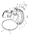
- Figure 1 is an enlarged view of the light (27) showing the different parts forming the improvements to this Additional European Patent application.
- Figure 2 is an enlarged view of the main features of the cup (60) connected to the reflector (14) using connection piece (73).
- the light (27) in this European Patent No. 6.380.159.1 has no lamp holders (22) drawn with this number in Figure 1 of this patent. These have been replaced by a cup (60) in order to make fine adjustments of the light as shown in Figure 2.
- the cup (60) is formed by a lamp holder support (62) as shown in Figure 2, an adjustment wheel (63) and means to guide the lamp holder (59), which fit into the connection piece (57), mounted (57) on the reflector (14) using conventional screws not shown in the drawing. These screws pass through drilled holes (66) made in (57) allowing the connection piece (57) to be attached to the reflector (14).
- connection piece (57) is formed by a flat and ring piece (65) and a skirt (68) appearing from its inner edge.
- the lamp (58) is attached by a screwed thread or other equivalent method for lamp holders (59), as shown in Figure 2.
- this is (59) fixed using screws (72) to the supports (62), with these supports (62) having a slotted area (71) which stops the lamp holder (59) to (62) from moving in the different positions shown for illustrative purposes as letters A, B, C, D, E, and F.
- These positions shown as letters holding screws (72)in slot (71) hold the position of the lamp (58) in a more or less advanced position in a longitudinal direction inside the reflector (14).
- the support (62) is formed by an ring area (74) which extended vertically downwards according to skirts (75), which (75) has some longitudinal guide ribs (70) on its upper surface. These contain hidden slots shown in Figure 2 equipped with a connection piece (57) in a skirt (68).
- connection piece (57), as shown in Figure 2 is formed by a flat ring shaped piece (65) which is extended around its inner edge by a skirt (68). The surface of this has some ribs (69) which butt up to the circular area or joint (76). Also in the flat area there are drilled holes (66) for holding the support (62) to the reflector (14). Lugs (64) have been located in the connection area emerging from the ring area (74).
- the lugs (64) are located in the connection area (67) which has been drilled so that these lugs (64) can pass through.
- By turning the ring area (74) allow the cup (60) to be connected to the reflector (14), pressing the joint (76) located below the flat area (73) on the wheel (63) the flat area (65) of the connection piece (57) making the whole assembly (14-60) completely sealed.
- a single inner thread finely adjusts the lamp holder (59) or makes a second adjustment once all light components (27) have been assembled. In this way, its is first generally adjusted using the holding position for the lamp holder (59) in any of the positions A, B, C, D, E, F. There is then a fine adjustment by rotating the wheel (63).
Landscapes
- Engineering & Computer Science (AREA)
- General Engineering & Computer Science (AREA)
- Fastening Of Light Sources Or Lamp Holders (AREA)
Priority Applications (1)
| Application Number | Priority Date | Filing Date | Title |
|---|---|---|---|
| EP06380230A EP1892466A1 (de) | 2006-08-21 | 2006-08-21 | Halter für eine Lichtquelle |
Applications Claiming Priority (1)
| Application Number | Priority Date | Filing Date | Title |
|---|---|---|---|
| EP06380230A EP1892466A1 (de) | 2006-08-21 | 2006-08-21 | Halter für eine Lichtquelle |
Publications (1)
| Publication Number | Publication Date |
|---|---|
| EP1892466A1 true EP1892466A1 (de) | 2008-02-27 |
Family
ID=37309384
Family Applications (1)
| Application Number | Title | Priority Date | Filing Date |
|---|---|---|---|
| EP06380230A Withdrawn EP1892466A1 (de) | 2006-08-21 | 2006-08-21 | Halter für eine Lichtquelle |
Country Status (1)
| Country | Link |
|---|---|
| EP (1) | EP1892466A1 (de) |
Citations (5)
| Publication number | Priority date | Publication date | Assignee | Title |
|---|---|---|---|---|
| EP0686805A1 (de) * | 1994-06-10 | 1995-12-13 | Thorn Europhane | Leuchte insbesondere Aussen- oder Industrieleuchte mit einem Reflektor und einem von diesem abnehmbaren Lampenfassungsträger |
| WO1996005467A1 (en) * | 1994-08-10 | 1996-02-22 | Lee, Larry, C., Y. | Quartz lamp with quick-release |
| EP0901202A2 (de) * | 1997-09-06 | 1999-03-10 | Hella KG Hueck & Co. | Reflektorleuchte |
| US6380159B1 (en) | 1997-12-23 | 2002-04-30 | Cornell Research Foundation, Inc. | Genes for male accessory gland proteins in drosophila melanogaster |
| DE10241900A1 (de) * | 2002-09-06 | 2004-03-25 | Siemens Ag | Beleuchtungsvorrichtung |
-
2006
- 2006-08-21 EP EP06380230A patent/EP1892466A1/de not_active Withdrawn
Patent Citations (5)
| Publication number | Priority date | Publication date | Assignee | Title |
|---|---|---|---|---|
| EP0686805A1 (de) * | 1994-06-10 | 1995-12-13 | Thorn Europhane | Leuchte insbesondere Aussen- oder Industrieleuchte mit einem Reflektor und einem von diesem abnehmbaren Lampenfassungsträger |
| WO1996005467A1 (en) * | 1994-08-10 | 1996-02-22 | Lee, Larry, C., Y. | Quartz lamp with quick-release |
| EP0901202A2 (de) * | 1997-09-06 | 1999-03-10 | Hella KG Hueck & Co. | Reflektorleuchte |
| US6380159B1 (en) | 1997-12-23 | 2002-04-30 | Cornell Research Foundation, Inc. | Genes for male accessory gland proteins in drosophila melanogaster |
| DE10241900A1 (de) * | 2002-09-06 | 2004-03-25 | Siemens Ag | Beleuchtungsvorrichtung |
Similar Documents
| Publication | Publication Date | Title |
|---|---|---|
| AU3358699A (en) | Controls for a surgical light apparatus | |
| CN111765402A (zh) | 一种具有防眩装置的探照灯 | |
| EP1892466A1 (de) | Halter für eine Lichtquelle | |
| CN117148650A (zh) | 一种基于视觉检测的可调式补光装置及补光方法 | |
| KR101701886B1 (ko) | 등명기 | |
| CN204083996U (zh) | 机械可调节式筒灯 | |
| CN203963751U (zh) | 车用迎宾灯 | |
| EP3591282A1 (de) | Lampeneinheitsträgerstruktur für scheinwerfer und scheinwerferherstellungsverfahren | |
| CN208794133U (zh) | 台灯配光结构 | |
| KR20130004277U (ko) | 스포트라이트 조명등 | |
| CN210291472U (zh) | 新型可调式手电筒 | |
| CN208365415U (zh) | 车辆用灯具 | |
| CN210165320U (zh) | 一种变焦组件及变焦灯具 | |
| KR101104855B1 (ko) | 빔 조절가능 벽등 | |
| KR20190055369A (ko) | 유지보수가 용이한 등기구의 조립구조 | |
| CN220417149U (zh) | 透镜固定结构、灯具及照明系统 | |
| CN209445095U (zh) | 一种灯具 | |
| CN112197187A (zh) | 一种台灯光照范围的调节方法 | |
| CN223924656U (zh) | 一种草坪灯 | |
| KR101663930B1 (ko) | 현수막 거치장치 | |
| CN222142807U (zh) | 一种可穿孔厚型材安装的点光源 | |
| CN220379624U (zh) | 一种多功能文旅投影式智慧庭院灯 | |
| CN205640563U (zh) | 一种清晰度可调的logo坎灯 | |
| CN219453804U (zh) | 一种万向可调射灯 | |
| CN218001239U (zh) | 一种高光效防炫目台灯 |
Legal Events
| Date | Code | Title | Description |
|---|---|---|---|
| PUAI | Public reference made under article 153(3) epc to a published international application that has entered the european phase |
Free format text: ORIGINAL CODE: 0009012 |
|
| AK | Designated contracting states |
Kind code of ref document: A1 Designated state(s): AT BE BG CH CY CZ DE DK EE ES FI FR GB GR HU IE IS IT LI LT LU LV MC NL PL PT RO SE SI SK TR |
|
| AX | Request for extension of the european patent |
Extension state: AL BA HR MK YU |
|
| 17P | Request for examination filed |
Effective date: 20080314 |
|
| 17Q | First examination report despatched |
Effective date: 20080418 |
|
| AKX | Designation fees paid |
Designated state(s): AT BE BG CH CY CZ DE DK EE ES FI FR GB GR HU IE IS IT LI LT LU LV MC NL PL PT RO SE SI SK TR |
|
| STAA | Information on the status of an ep patent application or granted ep patent |
Free format text: STATUS: THE APPLICATION IS DEEMED TO BE WITHDRAWN |
|
| 18D | Application deemed to be withdrawn |
Effective date: 20110802 |