EP1892439A2 - Hydrostatisches Getriebe - Google Patents
Hydrostatisches Getriebe Download PDFInfo
- Publication number
- EP1892439A2 EP1892439A2 EP07114508A EP07114508A EP1892439A2 EP 1892439 A2 EP1892439 A2 EP 1892439A2 EP 07114508 A EP07114508 A EP 07114508A EP 07114508 A EP07114508 A EP 07114508A EP 1892439 A2 EP1892439 A2 EP 1892439A2
- Authority
- EP
- European Patent Office
- Prior art keywords
- poppet
- hydrostatic transmission
- bypass orifice
- trunnion shaft
- bypass
- Prior art date
- Legal status (The legal status is an assumption and is not a legal conclusion. Google has not performed a legal analysis and makes no representation as to the accuracy of the status listed.)
- Granted
Links
Images




Classifications
-
- F—MECHANICAL ENGINEERING; LIGHTING; HEATING; WEAPONS; BLASTING
- F16—ENGINEERING ELEMENTS AND UNITS; GENERAL MEASURES FOR PRODUCING AND MAINTAINING EFFECTIVE FUNCTIONING OF MACHINES OR INSTALLATIONS; THERMAL INSULATION IN GENERAL
- F16H—GEARING
- F16H61/00—Control functions within control units of change-speed- or reversing-gearings for conveying rotary motion ; Control of exclusively fluid gearing, friction gearing, gearings with endless flexible members or other particular types of gearing
- F16H61/38—Control of exclusively fluid gearing
- F16H61/40—Control of exclusively fluid gearing hydrostatic
-
- F—MECHANICAL ENGINEERING; LIGHTING; HEATING; WEAPONS; BLASTING
- F16—ENGINEERING ELEMENTS AND UNITS; GENERAL MEASURES FOR PRODUCING AND MAINTAINING EFFECTIVE FUNCTIONING OF MACHINES OR INSTALLATIONS; THERMAL INSULATION IN GENERAL
- F16H—GEARING
- F16H61/00—Control functions within control units of change-speed- or reversing-gearings for conveying rotary motion ; Control of exclusively fluid gearing, friction gearing, gearings with endless flexible members or other particular types of gearing
- F16H61/38—Control of exclusively fluid gearing
- F16H61/40—Control of exclusively fluid gearing hydrostatic
- F16H61/4035—Control of circuit flow
-
- F—MECHANICAL ENGINEERING; LIGHTING; HEATING; WEAPONS; BLASTING
- F16—ENGINEERING ELEMENTS AND UNITS; GENERAL MEASURES FOR PRODUCING AND MAINTAINING EFFECTIVE FUNCTIONING OF MACHINES OR INSTALLATIONS; THERMAL INSULATION IN GENERAL
- F16H—GEARING
- F16H61/00—Control functions within control units of change-speed- or reversing-gearings for conveying rotary motion ; Control of exclusively fluid gearing, friction gearing, gearings with endless flexible members or other particular types of gearing
- F16H61/38—Control of exclusively fluid gearing
- F16H61/40—Control of exclusively fluid gearing hydrostatic
- F16H61/4043—Control of a bypass valve
-
- F—MECHANICAL ENGINEERING; LIGHTING; HEATING; WEAPONS; BLASTING
- F16—ENGINEERING ELEMENTS AND UNITS; GENERAL MEASURES FOR PRODUCING AND MAINTAINING EFFECTIVE FUNCTIONING OF MACHINES OR INSTALLATIONS; THERMAL INSULATION IN GENERAL
- F16H—GEARING
- F16H59/00—Control inputs to control units of change-speed- or reversing-gearings for conveying rotary motion
- F16H59/68—Inputs being a function of gearing status
- F16H2059/6823—Sensing neutral state of the transmission
-
- F—MECHANICAL ENGINEERING; LIGHTING; HEATING; WEAPONS; BLASTING
- F16—ENGINEERING ELEMENTS AND UNITS; GENERAL MEASURES FOR PRODUCING AND MAINTAINING EFFECTIVE FUNCTIONING OF MACHINES OR INSTALLATIONS; THERMAL INSULATION IN GENERAL
- F16H—GEARING
- F16H59/00—Control inputs to control units of change-speed- or reversing-gearings for conveying rotary motion
- F16H59/68—Inputs being a function of gearing status
- F16H2059/6838—Sensing gearing status of hydrostatic transmissions
- F16H2059/6853—Sensing gearing status of hydrostatic transmissions the state of the transmission units, i.e. motor or pump capacity, e.g. for controlled shifting of range gear
-
- F—MECHANICAL ENGINEERING; LIGHTING; HEATING; WEAPONS; BLASTING
- F16—ENGINEERING ELEMENTS AND UNITS; GENERAL MEASURES FOR PRODUCING AND MAINTAINING EFFECTIVE FUNCTIONING OF MACHINES OR INSTALLATIONS; THERMAL INSULATION IN GENERAL
- F16H—GEARING
- F16H61/00—Control functions within control units of change-speed- or reversing-gearings for conveying rotary motion ; Control of exclusively fluid gearing, friction gearing, gearings with endless flexible members or other particular types of gearing
- F16H61/38—Control of exclusively fluid gearing
- F16H61/40—Control of exclusively fluid gearing hydrostatic
- F16H61/42—Control of exclusively fluid gearing hydrostatic involving adjustment of a pump or motor with adjustable output or capacity
- F16H61/439—Control of the neutral position, e.g. by zero tilt rotation holding means
Definitions
- the invention relates to hydrostatic transmissions for work vehicles, and particularly to hydrostatic transmissions used on grass mowing machines having a hydrostatic transmission to control the direction of rotation and speed of traction drive wheels.
- Hydrostatic transmissions for work vehicles such as grass mowing machines may be used to control direction and speed of traction drive wheels.
- the vehicle operator may move operator controls to turn a trunnion shaft or control arm on the hydrostatic transmission. Turning the trunnion shaft or control arm also will change the rotational speed of the wheel.
- shifting the hydrostatic transmission from neutral into forward or reverse such vehicles have a tendency to be somewhat jerky or bouncy, as the operator may not be able to smoothly control the transition from neutral. Additionally, the vehicle may experience dynamic braking, which may result in turf damage due to tire slippage and scuffing.
- Hydrostatic transmissions may include a pump with a bleed passage or bypass orifice in the closed loop section of the hydraulic circuit.
- the bypass orifice may be included in the hydraulic circuit to help soften the abrupt transition between neutral and forward or reverse by broadening the neutral zone of the hydrostatic transmission.
- the bypass orifice also can provide a softer application of dynamic braking, which may reduce turf damage and enhance the vehicle's overall control, especially when mowing on a slope or hillside.
- a bypass orifice can help adjust and index the neutral position of the operator controls to the hydrostatic pump's exact hydraulic neutral.
- Hydrostatic transmissions with very small and/or no closed loop bleed passage or bypass orifice exhibit a very tight neutral or no-flow position zone.
- hydrostatic transmissions equipped with larger bleed orifices have a large neutral zone, and are much easier to adjust to a no-creep position.
- bypass orifices may have disadvantages.
- bypass orifices may contribute to increased temperatures as loop pressures increase. Accordingly, a bypass orifice for a hydrostatic transmission is needed that provides a neutral zone sufficient to provide a smooth transition between neutral and forward or reverse, without increasing temperatures.
- a bypass orifice is needed that will help increase pump performance, and simplify assembly.
- a hydrostatic transmission of a work vehicle such as a grass mowing machine.
- a charge pump provides hydraulic fluid to a plurality of high pressure ports, each high pressure port having a charge system bypass valve.
- the shift controlled bypass orifice may connect to each charge system bypass valve.
- a poppet may close the bypass orifice in response to operator controls shifting the hydrostatic transmission to a non-neutral position.
- a trunnion shaft may cam the poppet to close the bypass orifice in response to movement of operator controls to the non-neutral position, and open as the operator moves the controls closer to neutral.
- An inventive hydrostatic transmission comprises a charge pump providing hydraulic fluid to a plurality of high pressure ports, each high pressure port having a charge system bypass valve; wherein a bypass orifice connecting to each charge system bypass valve; and a poppet valve closing the bypass orifice in response to the hydrostatic transmission moving to a non-neutral position.
- a trunnion shaft may cam the poppet to close the bypass orifice in response to movement of an operator control to a non-neutral position.
- An operator control may be connected to the trunnion shaft, the operator control turning the trunnion shaft between a neutral position, a forward position, and a reverse position.
- a spring may bias the poppet valve to open the bypass orifice.
- a poppet cap, and a spring between the poppet cap and the poppet valve may be provided.
- the bypass orifice may be transverse to the high pressure ports.
- a bleed passage may be provided through the poppet valve.
- a hydrostatic transmission may comprise a pump valve body having a plurality of high pressure ports through which hydraulic fluid flows between a pump and a motor; a bypass orifice in the pump valve body and extending between the high pressure ports and the pump valve body; a bleed poppet movable between a closed position blocking the bypass orifice and an open position opening the bypass orifice; a poppet push pin moving the bleed poppet toward the open position if the hydrostatic transmission is in neutral, and toward the closed position if the hydrostatic transmission is in forward or reverse.
- the trunnion shaft may have a groove, the poppet push pin riding on the trunnion shaft.
- a spring may be provided to bypass the bleed poppet.
- the bleed poppet may be transverse to the bypass orifice.
- a bleed passage may be provided through the bleed poppet.
- a hydrostatic transmission may comprise a bypass orifice extending through a pump valve body of the hydrostatic transmission; at least one operator control pivoting to move the hydrostatic transmission between a neutral position, a forward position, and a reverse position; and a poppet valve transverse to the bypass orifice, the poppet valve opening the bypass orifice further as the operator controls are pivoted further toward the neutral position, the poppet valve closing the bypass orifice further as the operator controls are pivoted further toward the forward or reverse positions.
- Each operator control may be a pivoting stick.
- Each operator control may be attached to a trunnion shaft, the trunnion shaft having a cylindrical outer surface with an axial groove.
- the hydrostatic transmission may be a dual hydrostatic transmission.
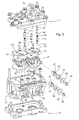
- Figs. 1-5 show an embodiment of the shift controlled bypass orifice in hydrostatic transmission 10.
- the hydrostatic transmission includes dual pump valve body 11, main housing 12, charge pump 13, and lower housing 15.
- the shift controlled bypass orifice also may be included in a hydrostatic transmission having a single pump valve body.
- Charge pump 13 may be a rotary pump operatively connected to a rotating shaft of an internal combustion engine, electric motor or other power source, and may supply hydraulic fluid to charge port 14.
- the pump valve body also may include a pair of valve plates 33, 34.
- charge system bypass valves 17, 18 may open to allow hydraulic fluid in charge port 14 to enter and maintain sufficient hydraulic fluid pressure in high pressure ports 19, 20.
- Each charge system bypass valve may include a check ball that is spring biased to a closed position.
- Each charge system bypass valve may open if hydraulic fluid pressure in charge port 14 exceeds the hydraulic pressure in high pressure ports 19, 20 sufficiently to overcome the spring force and unseat the check ball.
- hydraulic lines may connect high pressure ports 19, 20 to a hydraulic motor which rotates a traction drive wheel to move the vehicle forward or in reverse. If it is necessary to rotate the traction drive wheel without operating the hydrostatic transmission, bypass valve 24 may be retracted from crossover passage 25, allowing hydraulic fluid to circulate freely between high pressure ports 19 and 20.
- trunnion shafts or control arms 26, 27 may extend through main housing 12, and may turn to pivot swash plates.
- the trunnion shafts or control arms 26, 27 may be turned using various operator controls, such as pivoting sticks that are commonly used to operate zero turning radius mowers.
- the operator controls may be used to turn the trunnion shafts to shift between neutral and forward or reverse, and change the speed in forward or reverse, by changing the angle of the swash plate.
- Each swash plate controls the position and displacement of pistons in a piston cylinder block 30, 31, to specify the direction and flow of hydraulic fluid from high pressure ports 19, 20 through hydraulic lines to a hydraulic motor.
- each trunnion shaft or control arm 26, 27 may be a generally cylindrical shaft having a groove 37, 38.
- Each trunnion shaft or control arm may be inserted through bushing 39, 40, oil seal 52, 53, washer 54, 55 and lock ring 56, 57 positioned in openings 58, 59 in main housing 12.
- Each bushing may have an aperture 41, 42 though which poppet push pin 43, 44 may extend to ride on and be directly activated off the trunnion shaft or control arm.
- each poppet push pin 43, 44 may activate spring biased bleed poppet 45, 46 to slide into poppet cap 48, 49, opening or closing shift controlled bypass orifice 47.
- Each poppet cap 48, 49 may protrude through the top of the pump valve body.
- Springs 63, 64 may be positioned between each bleed poppet and poppet cap to maintain contact between the bleed poppet, poppet push pin, and trunnion shaft.
- the top of each poppet cap may be closed by plug 71, 72.
- the shift controlled bypass orifice may extend from the charge system bypass valves to the outer wall of the pump valve body where it may be connected to a conduit to hydraulic fluid reservoir.
- the control turns the trunnion shaft, and poppet push pin 43, 44 pushes bleed poppet 45, 46 up to close the shift controlled bypass orifice, or down to open the shift controlled bypass orifice.
- the shift controlled bypass orifice also may include an aperture 49, 50 through the holder wall of each charge system bypass valve 17, 18.
- trunnion shaft 26 is shown in a neutral position.
- Shift controlled bypass orifice 47 is open because bleed poppet 45 has moved down as poppet push pin 43 rides down into groove 37 in trunnion shaft 26.
- bleed poppet 45 slides down and further out from poppet cap 48 to open the shift controlled bypass orifice.
- trunnion shaft 26 is shown in a forward or reverse position. Shift controlled bypass orifice 47 is closed because bleed poppet 45 has been pushed up by poppet push pin 43 riding on the outer diameter of trunnion shaft 26. The poppet push pin cams upward, urging bleed poppet 45 to slide up further into poppet cap 48, to close the shift controlled bypass orifice.
- each trunnion shaft may turn about twenty degrees between a neutral position and a maximum forward position, and about twenty degrees from neutral to maximum reverse.
- Groove 37 on the trunnion shaft may be dimensioned so that the shift controlled bypass orifice is completely open for about ten percent of the trunnion shaft's total range of rotation between neutral and forward, and between neutral and reverse. This means the groove is dimensioned so that the shift controlled bypass orifice is completely open, most preferably about two degrees, or in a range of between about one degree and about three degrees, of trunnion shaft rotation on each side of the neutral position.
- bleed orifice 65 may extend through bleed poppet 45. Hydraulic fluid flowing through the open shift controlled bypass may flow between the bleed poppet and poppet cap, through bleed orifice 65, and out around the top of poppet push pin 43 into the case.
- the top surface of poppet push pin 43 may have a groove 74 so that hydraulic fluid is not trapped in bleed orifice 65.
- shift controlled bypass orifice 47 may have an internal diameter equal to or greater than bleed orifice 65 through the bleed poppet.
- bleed orifice 65 may have an internal diameter of between about 0,0254 cm (0.010 inches) and about 0,1143 cm (0.045 inches), and shift controlled bypass orifice may have an internal diameter that is the same or equal.
- bleed poppet 45 As trunnion shaft 26 pushes the poppet push pin 43 up and against bleed poppet 45, the bleed poppet progressively closes off shift controlled bypass orifice 47. At some degree of trunnion shaft rotation, bleed poppet 45 completely shuts off all bypass fluid flow through the shift controlled bypass orifice. The closer an operator control is to neutral, the more the bleed poppet opens the bypass orifice.
- the shift controlled bypass orifice may sequentially widen the neutral zone and allow for enhanced dynamic braking and vehicle control. As a result, the shift controlled bypass orifice effectively increases the hydraulic pump's performance, and also eliminates induced heat.
- the shift controlled bypass orifice of the present invention has a number of benefits and advantages, as set forth below.
- the shift controlled bypass orifice helps improve operator comfort and machine control by significantly reducing abrupt, jerky starts.
- the shift controlled bypass orifice helps achieve better control of a vehicle such as a grass mowing machine during turns and stops by providing softer dynamic braking.
- the shift controlled bypass orifice improves performance of a hydrostatic transmission as the vehicle approaches normal operating speeds because, as the bypass bleed is shut down, more of the closed loop fluid is directed to the wheel motors.
- the shift controlled bypass orifice helps increase the life of a hydrostatic transmission, and enhance vehicle performance and reliability, by reducing system operating temperatures.
- the shift controlled bypass orifice enhances vehicle safety by reducing or eliminating hard starts, reducing front end lift off, and effectively reducing creep in the neutral position while the engine is running.
- the shift controlled bypass orifice improves system reliability because hard start pressures are less spiked, reducing undesirable and adverse stresses on all system components.
- the shift controlled bypass orifice also can reduce vehicle maintenance requirements because the wider neutral zone of the hydrostatic transmission requires fewer and less frequent creep adjustments.
- the shift controlled bypass orifice helps reduce assembly time because locating and adjusting hydraulic neutral creep is much easier to attain.
- the shift controlled bypass orifice locates all controls and components inside a hydrostatic pump, and are less subject to damage or contamination than external components.
Landscapes
- Engineering & Computer Science (AREA)
- General Engineering & Computer Science (AREA)
- Mechanical Engineering (AREA)
- Control Of Fluid Gearings (AREA)
Applications Claiming Priority (1)
| Application Number | Priority Date | Filing Date | Title |
|---|---|---|---|
| US11/509,377 US7430861B2 (en) | 2006-08-24 | 2006-08-24 | Shift controlled bypass orifice for hydrostatic transmission |
Publications (3)
| Publication Number | Publication Date |
|---|---|
| EP1892439A2 true EP1892439A2 (de) | 2008-02-27 |
| EP1892439A3 EP1892439A3 (de) | 2010-06-02 |
| EP1892439B1 EP1892439B1 (de) | 2011-09-21 |
Family
ID=38596111
Family Applications (1)
| Application Number | Title | Priority Date | Filing Date |
|---|---|---|---|
| EP07114508A Ceased EP1892439B1 (de) | 2006-08-24 | 2007-08-17 | Hydrostatisches Getriebe |
Country Status (2)
| Country | Link |
|---|---|
| US (1) | US7430861B2 (de) |
| EP (1) | EP1892439B1 (de) |
Families Citing this family (2)
| Publication number | Priority date | Publication date | Assignee | Title |
|---|---|---|---|---|
| WO2010011637A1 (en) * | 2008-07-21 | 2010-01-28 | Strands, Inc | Ambient collage display of digital media content |
| US20110029928A1 (en) * | 2009-07-31 | 2011-02-03 | Apple Inc. | System and method for displaying interactive cluster-based media playlists |
Citations (3)
| Publication number | Priority date | Publication date | Assignee | Title |
|---|---|---|---|---|
| GB892049A (en) | 1959-04-10 | 1962-03-21 | Lucas Industries Ltd | Hydraulic power transmission means for vehicles |
| US3161137A (en) | 1961-06-12 | 1964-12-15 | Dowty Hydraulic Units Ltd | Hydraulic apparatus |
| US3224197A (en) | 1963-10-03 | 1965-12-21 | John A Lauck | Hydrostatic transmission |
Family Cites Families (11)
| Publication number | Priority date | Publication date | Assignee | Title |
|---|---|---|---|---|
| US3451218A (en) * | 1967-09-01 | 1969-06-24 | Towmotor Corp | Compensator valve for hydrostatic transmission |
| US4896506A (en) * | 1987-11-18 | 1990-01-30 | Shivvers, Inc. | Transmission with integrated gear reduction |
| US4843817A (en) * | 1987-11-18 | 1989-07-04 | Shivvers, Inc. | Integrated hydraulic transmission |
| US6513325B2 (en) * | 1996-06-26 | 2003-02-04 | Kanzaki Kokyukoki Mfg. Co., Ltd. | Mechanism of returning to neutral for axle driving apparatus |
| US5979270A (en) * | 1997-07-09 | 1999-11-09 | Unipat Ag | Hydrostatic transaxle |
| US6253637B1 (en) * | 1998-11-20 | 2001-07-03 | Hydro-Gear Limited Partnership | Control device for hydrostatic apparatus |
| US6145312A (en) * | 1998-12-30 | 2000-11-14 | Hydro-Gear Limited Partnership | Electro-mechanical bypass for hydrostatic transmission |
| JP2002243037A (ja) * | 2001-02-19 | 2002-08-28 | Sauer-Danfoss-Daikin Ltd | 動力ユニット |
| US6672843B1 (en) * | 2002-04-08 | 2004-01-06 | Hydro-Gear Limited Partnership | Dual pump apparatus comprising dual drive shafts and auxiliary pump |
| US6837047B2 (en) * | 2002-07-12 | 2005-01-04 | Parker-Hannifin Corporation | Hydraulic devices for smooth operations of hydrostatic transmission |
| US7082759B1 (en) * | 2004-09-02 | 2006-08-01 | Michio Tsukamoto | Hydraulic drive vehicle |
-
2006
- 2006-08-24 US US11/509,377 patent/US7430861B2/en active Active
-
2007
- 2007-08-17 EP EP07114508A patent/EP1892439B1/de not_active Ceased
Patent Citations (3)
| Publication number | Priority date | Publication date | Assignee | Title |
|---|---|---|---|---|
| GB892049A (en) | 1959-04-10 | 1962-03-21 | Lucas Industries Ltd | Hydraulic power transmission means for vehicles |
| US3161137A (en) | 1961-06-12 | 1964-12-15 | Dowty Hydraulic Units Ltd | Hydraulic apparatus |
| US3224197A (en) | 1963-10-03 | 1965-12-21 | John A Lauck | Hydrostatic transmission |
Also Published As
| Publication number | Publication date |
|---|---|
| EP1892439A3 (de) | 2010-06-02 |
| EP1892439B1 (de) | 2011-09-21 |
| US20080047264A1 (en) | 2008-02-28 |
| US7430861B2 (en) | 2008-10-07 |
Similar Documents
| Publication | Publication Date | Title |
|---|---|---|
| US7921956B2 (en) | Hydraulic drive vehicle | |
| US7430863B2 (en) | Pump unit and hydrostatic transmission | |
| US9211793B2 (en) | Vehicle transaxle system | |
| US8347620B2 (en) | Bypass/flushing valve for closed hydraulic circuit | |
| US6837047B2 (en) | Hydraulic devices for smooth operations of hydrostatic transmission | |
| US9549504B2 (en) | Transaxle system for vehicle | |
| US20090145124A1 (en) | Hydraulic Transaxle | |
| US20220034067A1 (en) | Hydraulic Driving Apparatus | |
| US7320217B2 (en) | Load controller for hydrostatic transmission in work vehicles | |
| CN107532590A (zh) | 用于动力传动系统的正排量泵组件以及结合该组件的液压控制系统 | |
| US7383913B1 (en) | Hydraulic transaxle and vehicle comprising it | |
| CA2097202C (en) | Conduit valve providing wide neutral in a hydrostatic transmission | |
| EP1892439B1 (de) | Hydrostatisches Getriebe | |
| US8820066B1 (en) | Steerable transaxle | |
| US6682453B1 (en) | Hydrostatic transaxle apparatus | |
| US9664270B1 (en) | Hydrostatic transmission | |
| AU759540B2 (en) | Electronically controlled dampener for hydrostatic transmission | |
| US6895748B2 (en) | Hydrostatic transmission having a hydraulic disconnect | |
| JP4034909B2 (ja) | 可変容量型油圧ポンプの斜板制御装置 | |
| US20040123594A1 (en) | Hydrostatic transmission having a hydraulic dampening and neutral bleed mechanism | |
| JP3613365B2 (ja) | Hst式ミッション装置 | |
| US10895249B2 (en) | Hydraulic transaxle | |
| JP2000225864A (ja) | 油圧式無段変速装置の中立保持機構 | |
| JP2007170612A (ja) | 流体圧伝動装置および機械 | |
| JP2009179153A (ja) | ロータリバルブ |
Legal Events
| Date | Code | Title | Description |
|---|---|---|---|
| PUAI | Public reference made under article 153(3) epc to a published international application that has entered the european phase |
Free format text: ORIGINAL CODE: 0009012 |
|
| AK | Designated contracting states |
Kind code of ref document: A2 Designated state(s): AT BE BG CH CY CZ DE DK EE ES FI FR GB GR HU IE IS IT LI LT LU LV MC MT NL PL PT RO SE SI SK TR |
|
| AX | Request for extension of the european patent |
Extension state: AL BA HR MK YU |
|
| PUAL | Search report despatched |
Free format text: ORIGINAL CODE: 0009013 |
|
| AK | Designated contracting states |
Kind code of ref document: A3 Designated state(s): AT BE BG CH CY CZ DE DK EE ES FI FR GB GR HU IE IS IT LI LT LU LV MC MT NL PL PT RO SE SI SK TR |
|
| AX | Request for extension of the european patent |
Extension state: AL BA HR MK RS |
|
| 17P | Request for examination filed |
Effective date: 20101202 |
|
| AKX | Designation fees paid |
Designated state(s): DE GB |
|
| RIC1 | Information provided on ipc code assigned before grant |
Ipc: F16H 61/40 20100101AFI20110203BHEP |
|
| GRAP | Despatch of communication of intention to grant a patent |
Free format text: ORIGINAL CODE: EPIDOSNIGR1 |
|
| GRAS | Grant fee paid |
Free format text: ORIGINAL CODE: EPIDOSNIGR3 |
|
| GRAA | (expected) grant |
Free format text: ORIGINAL CODE: 0009210 |
|
| AK | Designated contracting states |
Kind code of ref document: B1 Designated state(s): DE GB |
|
| REG | Reference to a national code |
Ref country code: GB Ref legal event code: FG4D |
|
| REG | Reference to a national code |
Ref country code: DE Ref legal event code: R096 Ref document number: 602007017322 Country of ref document: DE Effective date: 20111215 |
|
| PLBE | No opposition filed within time limit |
Free format text: ORIGINAL CODE: 0009261 |
|
| STAA | Information on the status of an ep patent application or granted ep patent |
Free format text: STATUS: NO OPPOSITION FILED WITHIN TIME LIMIT |
|
| 26N | No opposition filed |
Effective date: 20120622 |
|
| REG | Reference to a national code |
Ref country code: DE Ref legal event code: R097 Ref document number: 602007017322 Country of ref document: DE Effective date: 20120622 |
|
| PGFP | Annual fee paid to national office [announced via postgrant information from national office to epo] |
Ref country code: DE Payment date: 20190719 Year of fee payment: 13 |
|
| REG | Reference to a national code |
Ref country code: DE Ref legal event code: R119 Ref document number: 602007017322 Country of ref document: DE |
|
| PG25 | Lapsed in a contracting state [announced via postgrant information from national office to epo] |
Ref country code: DE Free format text: LAPSE BECAUSE OF NON-PAYMENT OF DUE FEES Effective date: 20210302 |
|
| PGFP | Annual fee paid to national office [announced via postgrant information from national office to epo] |
Ref country code: GB Payment date: 20230828 Year of fee payment: 17 |
|
| GBPC | Gb: european patent ceased through non-payment of renewal fee |
Effective date: 20240817 |
|
| PG25 | Lapsed in a contracting state [announced via postgrant information from national office to epo] |
Ref country code: GB Free format text: LAPSE BECAUSE OF NON-PAYMENT OF DUE FEES Effective date: 20240817 |