EP1892428A1 - Core perimeter screw, assembly and method for secure mounting and/or replacement of core perimeter screws - Google Patents
Core perimeter screw, assembly and method for secure mounting and/or replacement of core perimeter screws Download PDFInfo
- Publication number
- EP1892428A1 EP1892428A1 EP07016525A EP07016525A EP1892428A1 EP 1892428 A1 EP1892428 A1 EP 1892428A1 EP 07016525 A EP07016525 A EP 07016525A EP 07016525 A EP07016525 A EP 07016525A EP 1892428 A1 EP1892428 A1 EP 1892428A1
- Authority
- EP
- European Patent Office
- Prior art keywords
- kernumfassungsschraube
- screw head
- screw
- locking plate
- anformung
- Prior art date
- Legal status (The legal status is an assumption and is not a legal conclusion. Google has not performed a legal analysis and makes no representation as to the accuracy of the status listed.)
- Granted
Links
Images


Classifications
-
- F—MECHANICAL ENGINEERING; LIGHTING; HEATING; WEAPONS; BLASTING
- F16—ENGINEERING ELEMENTS AND UNITS; GENERAL MEASURES FOR PRODUCING AND MAINTAINING EFFECTIVE FUNCTIONING OF MACHINES OR INSTALLATIONS; THERMAL INSULATION IN GENERAL
- F16B—DEVICES FOR FASTENING OR SECURING CONSTRUCTIONAL ELEMENTS OR MACHINE PARTS TOGETHER, e.g. NAILS, BOLTS, CIRCLIPS, CLAMPS, CLIPS OR WEDGES; JOINTS OR JOINTING
- F16B39/00—Locking of screws, bolts or nuts
- F16B39/02—Locking of screws, bolts or nuts in which the locking takes place after screwing down
- F16B39/10—Locking of screws, bolts or nuts in which the locking takes place after screwing down by a plate, spring, wire or ring immovable with regard to the bolt or object and mainly perpendicular to the axis of the bolt
- F16B39/103—Locking of screws, bolts or nuts in which the locking takes place after screwing down by a plate, spring, wire or ring immovable with regard to the bolt or object and mainly perpendicular to the axis of the bolt with a locking cup washer, ring or sleeve surrounding the nut or bolt head and being partially deformed on the nut or bolt head, or on the object itself
- F16B39/105—Locking of screws, bolts or nuts in which the locking takes place after screwing down by a plate, spring, wire or ring immovable with regard to the bolt or object and mainly perpendicular to the axis of the bolt with a locking cup washer, ring or sleeve surrounding the nut or bolt head and being partially deformed on the nut or bolt head, or on the object itself locking the bold head or nut into a hole or cavity, e.g. with the cup washer, ring or sleeve deformed into a dimple in the cavity
-
- F—MECHANICAL ENGINEERING; LIGHTING; HEATING; WEAPONS; BLASTING
- F16—ENGINEERING ELEMENTS AND UNITS; GENERAL MEASURES FOR PRODUCING AND MAINTAINING EFFECTIVE FUNCTIONING OF MACHINES OR INSTALLATIONS; THERMAL INSULATION IN GENERAL
- F16B—DEVICES FOR FASTENING OR SECURING CONSTRUCTIONAL ELEMENTS OR MACHINE PARTS TOGETHER, e.g. NAILS, BOLTS, CIRCLIPS, CLAMPS, CLIPS OR WEDGES; JOINTS OR JOINTING
- F16B35/00—Screw-bolts; Stay-bolts; Screw-threaded studs; Screws; Set screws
- F16B35/04—Screw-bolts; Stay-bolts; Screw-threaded studs; Screws; Set screws with specially-shaped head or shaft in order to fix the bolt on or in an object
- F16B35/06—Specially-shaped heads
-
- Y—GENERAL TAGGING OF NEW TECHNOLOGICAL DEVELOPMENTS; GENERAL TAGGING OF CROSS-SECTIONAL TECHNOLOGIES SPANNING OVER SEVERAL SECTIONS OF THE IPC; TECHNICAL SUBJECTS COVERED BY FORMER USPC CROSS-REFERENCE ART COLLECTIONS [XRACs] AND DIGESTS
- Y02—TECHNOLOGIES OR APPLICATIONS FOR MITIGATION OR ADAPTATION AGAINST CLIMATE CHANGE
- Y02E—REDUCTION OF GREENHOUSE GAS [GHG] EMISSIONS, RELATED TO ENERGY GENERATION, TRANSMISSION OR DISTRIBUTION
- Y02E30/00—Energy generation of nuclear origin
- Y02E30/30—Nuclear fission reactors
Definitions
- the invention relates to a Kernum chargedsschraube, an arrangement with Kernum interruptedsschraube and locking plate for secure installation and / or replacement of Kernum chargedsschrauben for mounting Kernum interruptedsblechen and a method for installation and / or replacement of Kernum directedsschrauben in a reactor pressure vessel, according to the preambles of the independent claims.
- Common reactor pressure vessels with internals include, for example, the actual reactor or core container, a loading and unloading system for introducing and removing or replacing the control rods and a support structure in which the reactor core rests and which distributes the coolant flow to the individual fuel elements.
- This usually provides a Kernum charged, an upper support plate, a lower support plate, a lower grid plate, and a flow distributor and an inner frame cylinder before.
- further internals may be provided, such as nozzles for the control drive, an overflow device, guide tubes for êtkerninstrumenttechnik, a control guide tube and an upper grid plate.
- the Kernum charged is thereby formed of several Kernum chargedsblechen which with Kernum executedsschrauben on-the-form ribs of the reactor pressure vessel or the Core scaffold be attached.
- a corresponding screw connection comprises the respective core surround screw, usually a screw with thread M12, a locking plate and a spacer.
- the Kernum forcedsschraube is secured against rotation and / or loosening in the locking plate by welding and sanded largely smooth to avoid supernatants with the locking plate.
- the core containment plates of the reactor are mounted dry before commissioning of the reactor, ensure a rectified and uniform flow of the coolant over the entire cross section of the active core and protected the actual reactor pressure vessel from the effects of neutron radiation. After flooding the reactor pressure vessel and commissioning of the reactor repair or replacement of the aforementioned internals is possible only under difficult conditions, with a repair concept during operation of the reactor is not present.
- the invention is based on the object to provide a simplified repair concept for core enclosures and in particular a simplified way for the replacement or renewal of Kernum distributedsschrauben.
- the core encompassing screw according to the invention has a shaft with an external thread and a screw head with a profile, preferably an external hexagon, which has an at least partially encircling formation.
- the Anformung can be formed, for example, like a ring or collar like screw head collar.
- the Anformung is formed mechanically deformable and has an advantageous embodiment of the Kernum chargedsschraube a material thickness of about 0.5 mm.
- the Anformung in particular designed as a screw head collar Anformung, while integrally formed or divided into a plurality of individual segments.
- the formed as a screw head collar Anformung includes flush with the upper edge or profile surface of the screw head.
- the screw head collar has a lower collar height than the screw head, in particular the screw head designed as an external hexagon.
- the transition region between the shaft and the head of the screw has, in an advantageous development, a parabolic shape, whereby the stress distribution in the transition region is improved.
- an arrangement for the secure installation of Kernum chargedsschrauben for assembly of Kernum chargedsblechen which comprises at least one Kernum drawnsschraube and at least one locking plate, wherein the Kernum chargedsschraube a screw shaft with external thread and a screw head with profile, preferably an external hexagon includes, which screw head an at least partially Has circumferential Anformung and wherein at least one counterbore for receiving the screw head, a first recess, in particular a hole or a hole for penetration of the Kernum chargedsschraube and mechanical security of the Kernum chargedsschraube against rotation at least one recess for engaging the sortedenkopfanformung are provided after mechanical deformation in the locking plate ,
- the Kernum forcedsschraube is installed torque controlled over the example hexagon of the screw head and secured by mechanical deformation of the Anformung against twisting or loosening in the at least one recess of the locking plate.
- the Anformung can be formed, for example, like a ring or as a screw head collar.
- a distance from the engagement of a corresponding tool such as the nut of a torque wrench or a ring wrench, provided for torque-controlled installation of Kernum forcedsschraube.
- the Anformung of the screw head is mechanically deformable and has an advantageous embodiment of the Kernum chargedsschraube a material thickness of about 0.5 mm.
- the Anformung in particular designed as a screw head collar Anformung, in one piece or as a plurality of individual segments.
- the Anformung of the screw head surrounds the screw head circumferentially at least partially, for example in the form of one or more ring or collar segments, which may also be arranged circumferentially spaced.
- the formed as a screw head collar Anformung concludes in an advantageous development of the upper edge of the screw head.
- the projection formed as a screw head collar has a lower collar height than the external hexagon of the screw head.
- transition region between the shaft and the head of the core surrounding screw is curved in an advantageous development, in particular formed with a parabolic course.
- the locking plate of the arrangement in its inner countersink in the bottom of a hole or a hole for the penetration of the Kernum chargedsschraube in the complementary internal thread of the mold ribs for fastening the respective Kernum shockedsbleches.
- the first recess of the countersink for passing through the core surround screw is preferably arranged centrally or centrally in the bottom of the countersink.
- At least one further recess is provided in the locking plate, in particular in the upper edge and / or wall region of the countersink, in which the Anformung of the screw head engages against mechanical deformation to secure the Kernum chargedsschraube against rotation. Also is an embodiment possible in which the at least one recess is arranged in the bottom region of the inner countersink.
- the locking plate in particular the upper edge region and / or the bottom portion of the countersink, four mutually offset by 90 ° recesses for engagement of the Anformung the screw head, in particular designed as a screw head collar Anformung, and thus for mechanical securing of the Kernum chargedsschraube.
- the countersink is configured in such a way that it completely accommodates the screw head with the shaping of the core surrounding screw and that the screw head is preferably flush with the upper side of the securing plate.
- the locking plate has an oval, insbesondre elliptical basic shape and rests in the installed state of Kernum chargedsschraube in a correspondingly shaped recess of Kernum forcedsbleches, whereby the locking plate secured against rotation relative to the Kernum forcedsblech and its installation is facilitated.
- the molding of the screw head in particular the Anformung formed as a screw head collar engages after installation of the Kernum chargedsschraube and mechanical deformation of the Anformung in at least one, in particular four offset by 90 °, recesses of the inner countersink of the lock washer.
- a first preparatory method step at least two holes are drilled through the core surround plate and / or a spacer located behind it and / or into the mold rib carrying the sheet metal and / or a locking pin is inserted into at least two of the drilled holes.
- the locking pins are inserted in such a way that they fix the spacer and / or and the core surround plate in its intended installation position and against each other, even after unscrewing the Kernum chargedsschraube and / or peeling off the locking plate.
- the locking pins are dimensioned with respect to their length such that they do not protrude beyond the Kernum chargedsblech or not survive, but in particular flush with this.
- the locking pins defined by depth stop pressed and / or secured by a press fit.
- a reworking of the seat of the locking plate is performed in a further intermediate step.
- At least one guide pin is installed in a further intermediate step after unscrewing the Kernum chargedsschraube and / or peeling off the locking plate to facilitate installation of the lock plate with countersink with recess for engagement of the fferenkopfanformung, in particular screwed into the threaded bore of the molding rib.
- the guide pin thereby advantageously engages through an optional spacer and the core surround sheet.
- the guide pin is unscrewed before inserting the lock plate with countersink with recess for engaging the SSenkopfanformung again and serves only as a guide for editing or post-processing of the seat.
- the mechanical deformation of the fferenkopfanformung carried out by means of a corresponding pressing or punching tool which presses the fferenkopfanformung partially in the space provided recesses of the locking plate, whereby the Kernum forcedsschraube is mechanically secured against rotation.
- FIG. 1 shows a side sectional view of a core surround plate mounted in a conventional manner on a rib, in particular during initial assembly, by means of a core surround screw and a lock washer. Accordingly, on the wall of a reactor pressure vessel core scaffold 1 - for simplification only partially shown here - Form ribs 2, each with a threaded bore 3 for receiving a Kernum chargedsschraube 4 for fixing a corresponding Kernum chargedsbleches 5 are provided.
- the locking plate 7 has an internal countersink with hole, in particular bore, for the penetration of the core surround screw 4 and engages in the installed state in a recess of Kernum chargedsbleches 5, whereby this is fixed after installation of the Kernum conductedsschraube 4 in its original position and orientation.
- the Kernum forcedsschraube 4 is thereby torque controlled screwed into the threaded hole 3 of the respective rib 2, wherein it passes through the locking plate 7, the Kernum chargedsblech 5 and the spacer 6 and this attached to the rib 2.
- the screw After screwing the Kernum chargedsschraube 4, the screw is usually secured by welding with the locking plate 7 against rotation and / or loosening.
- the surfaces of screw 4 and locking plate 7 are then flush ground to remove by the welding process supernatants and / or seams and to create a smooth, flat top or inner surface.
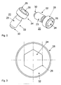
- FIG. 2 an exemplarily formed core surround screw 20 according to the invention is shown in a spatial representation from two different viewing directions.
- the aforementioned screw 20 in this case comprises a screw shaft 22 with external thread 23 and a screw head 24 with screw head profile, preferably external hexagon 26, which has an at least partially encircling, collar-like Anformung 28, hereinafter also referred to as a screw head collar has.
- the Anformung example also annular and / or be formed as a disc.
- the taper 30 can also be formed pyramidal or with any other geometric base.
- a running free area 32 for engagement of a corresponding tool such as the nut of a torque wrench or a ring wrench, provided for the torque-controlled installation of the core wrap screw 20.
- the free area 32 is formed like a groove.
- the screw head collar 28 is, in particular with regard to its material thickness, designed such that it is mechanically deformed relatively easily by the action of force and / or has a wall thickness or material thickness of about 0.5 mm.
- the aforementioned SSenkopfanformung in particular designed as a screw head collar 28 Anformung can be formed integrally or from individual segments. Furthermore, it can surround the screw head 24 with a profile, in particular the external hexagon 26 of the core surrounding screw 20, completely or, for example, if formed from individual segments, only partially, in particular in sections, circumferentially.
- Fig. 4 is a side sectional view of an exemplified trained Kernum forcedsschraube 20 with screw head collar 28 is shown.
- free shaft end 30 is tapered designed as a truncated cone to facilitate later attachment and / or screwing the Kernum chargedsschraube 20.
- tapered free shaft end 30 for example, pyramidal with square, triangular or polygonal, in particular hexagonal or octagonal base surface, possible.
- the shank 22 proportionately has an external thread 23, in particular an M12 thread, through which the screw 20 can be screwed and fixed in a complementary threaded bore of a shaped rib.
- a torque wrench with appropriate nut can be used.
- a screw head collar 28 is formed, which surrounds the head profile 26 circumferentially. Between screw head collar 28 and head profile 26, in particular an external hexagon, a distance is formed, so that a groove-shaped circumferentially encircling open area 32 is created, which allows the engagement of a corresponding tool for torque-controlled screwing the screw 20.
- the screw head collar 28 can also be formed from a plurality of individual segments, wherein the segments can surround the screw head 24 circumferentially only partially.
- the individual segments may be arranged circumferentially spaced from each other.
- the screw head collar 28 is designed such that it is flush with the head profile 26, that is, the collar height corresponds to the profile and / or head height.
- the screw head collar 28 may also have a smaller height than the screw head 24 or its profile 26, so that the screw head 24 protrudes or the profile 26 projects beyond the collar 28.
- the trained as a collar sterenkopfanformung 28 has a material thickness of in particular 0.5 mm.
- the transition region 36 between the shaft 22 and the head 24 of the screw is rotationally symmetrical and has, as shown in Fig. 4, a curved, in particular a nearly parabolic course.
- FIG. 5 shows a side sectional view of a core surround plate 5 mounted on a shaped rib 2, by means of an arrangement for the secure installation and / or replacement of core surround screws with at least one core surround screw 20 with screw head molding 28 and a locking plate 40.
- a spacer 6 is provided between the form of rib 2 and core surround plate 5.
- the core encompassing screw 20 according to FIG. 2 or FIG. 4 comprises a shaft 22 with external thread 23 and a screw head 24 with at least one protrusion 28 surrounding the screw head 24 at least proportionally circumferentially, which collar is formed like a collar in the example shown here.
- the locking plate 40 has, as also indicated in Fig. 7, an oval approximately elliptical basic shape, which rests in the installed state almost positively and accurately in a corresponding recess 41 of the Kernum chargedsbleches 5, whereby it is mechanically secured against rotation.
- the locking plate 40 As shown in Fig. 8 and Fig. 9, a trough-like inner countersink 42 with hole or bore 44 for receiving the screw head 24 and the penetration of the Kernum chargedsschraube 20 through the locking plate 40 and the Kernum conductedsblech 5 in the complementary threaded bore of a rib 2 on. Furthermore, the locking plate 40 and in particular its inner countersink 42 has four mutually offset by 90 ° recess 46 for engagement 48 of the collar-like designed SSenkopfanformung 28 for mechanical securing of the Kernum shockedsschraube 20th
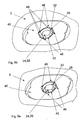
- FIG. 6 is a plan view of the mounted according to FIG. 5 Kernum chargedsblech 5 is shown, wherein the locking plate 40 rests in the complementary recess 41 of the respective Kernum forcedsbleches 5. Furthermore, in the region of the inner countersink 42 of the locking plate 40, the screw head 24 or its external hexagon profile 26 of the built-in core surround screw 20 with screw head collar 28 and between the profile 26 and collar 28 groove-shaped open area 32 indicated, the collar 28 has four deformations 48 which in the four recesses 46 of the locking plate 40 engage.
- the ringenkopfanformung may also be formed like a ring or disc, wherein the associated locking plate, the at least one recess for engaging the ringenkopfanformung 28 is then preferably arranged in the bottom region of the trough-like inner recess 42 of the locking plate 40.
- Fig. 7 is a side sectional view of a locking plate 40 with trough-like ausgestalteter inner countersink 42 for receiving the screw head 24 and hole or bore 44 for the penetration of the Kernum chargedsschraube 20 by the locking plate 40 and the Kernum conductedsblech 5 indicated in the complementary threaded bore of a shaped rib 2.
- the locking plate 40 and in particular its inner countersink 42 has four mutually offset by 90 ° recesses 46 for engaging the collar-like designed SSenkopfanformung 28 for mechanical securing of the Kernum shockedsschraube 20th
- any number of recesses 46 for engagement of the screw head collar 28 after deformation can be realized, for example, 1,2,3,6,8 etc.
- FIG. 8 shows a perspective view of a securing plate 40 according to FIGS. 6 and 7.
- the locking plate 40 has in a circular, trough-shaped inner countersink 42, in the bottom of a first recess 44, in particular a hole or hole, is provided for the penetration of the core screw 2 in the complementary threaded bore 3 of the molding ribs for fastening the respective Kernum chargedsbleches 5.
- the recess 44 in particular a bore, the inner countersink 42 for the passage of the core surround screw 20 is preferably arranged centrally or centrally in the bottom of the countersink.
- the locking plate 40 in particular in the upper edge region of the trough-shaped inner countersink 42, four bevels formed as chamfers further recesses 46 are provided, in which the Anformung 28 of the screw head 24 engages against mechanical deformation to secure the Kernum chargedsschraube 20 against rotation.
- the recesses 46 are offset by 90 ° to each other, but can also be arranged offset from each other at any other angle.
- the countersink 42 is designed such that it completely accommodates the screw head 24 with molding 28 of the core surrounding screw 20 and that the screw head 24 terminates flush with the upper side of the locking plate 40, as indicated in FIGS. 9a and 9b.
- FIG. 9a and FIG. 9b a spatial representation of the securing plate 40 resting in the core enclosing plate 20 according to FIG. 6 is shown, with the securing plate 40 also resting in the complementary recess 41 of the respective core enclosing plate 5. Furthermore, in the region of the inner countersink 42 of the securing plate 40, the screw head 24 or its external hexagonal profile 26 of the built-in core surrounding screw 20 with screw head collar 28 and the free-space 32 formed between profile 26 and collar 28 are indicated, wherein in FIG. 9b the collar 28 has four deformations 48 , which engage in the four recesses 46 of the locking plate 40.
- FIG. 10 is a sectional side view of one of a rib 2, by means of an arrangement for the secure installation and / or replacement of Kernum chargedsschrauben 4.20 with at least one Kernum chargedsschraube 20 with synchronenkopfanformung 28 and a locking plate 40 mounted Kernum forcedsbleches 5, for example after replacement of a Kernum forcedsschraube 4, shown.
- FIG. 5 a sectional representation of a core surround screw 20 according to the invention with clearly recognizable screw head molding 28 and free region 32 between screw head 24 and molding 28 is also shown.
- FIG. 10 at least two recesses, in particular holes 50 indicated which extend through the inserted spacer 6 and the respective Kernum chargedsblech 5 into the respective form of rib 2, wherein in at least two of the recesses, in particular bores 50, each used a locking pin 52 is.
- the purpose of the locking pins 52 is to hold the respective core enclosing plate 5 and the installed spacer 6 in position after unscrewing the core surrounding screw 4, 20.
- Bore depth and locking pin length are matched to one another such that each inserted locking pin 52 terminates with the respective Kernum chargedsblech 5 or ends before this.
- the pin 52 is in particular shorter than the bore 50 is formed.
- the post-processing of the seat of the locking plate can be carried out as needed.
Landscapes
- Engineering & Computer Science (AREA)
- General Engineering & Computer Science (AREA)
- Mechanical Engineering (AREA)
- Connection Of Plates (AREA)
Abstract
Kernumfassungsschraube (20), Anordnung und Verfahren für den gesicherten Einbau und/oder Austausch von Kernumfassungsschrauben (4,20) zur Montage von Kernumfassungsblechen (5) mit wenigstens einer Kernumfassungsschraube (20) sowie wenigstens einem Sicherungsblech (40), wobei die Kernumfassungsschraube (20) einen Schraubenkopf (24) mit zumindest einer, den Schraubenkopf (24) wenigstens anteilig umfänglich umgebenden Anformung (28) aufweist und im Sicherungsblech (40) wenigstens eine Innensenkung (42) zur Aufnahme des Schraubenkopfes (24) mit wenigstens einer ersten Ausnehmung (44), insbesondere einem Loch, zum Durchgriff der Kernumfassungsschraube (20) sowie wenigstens einer weiteren Ausnehmung (46) zum Eingriff der Schraubenkopfanformung (28) zur mechanischen Sicherung der Kernumfassungsschraube (20) gegen Verdrehen vorgesehen ist und die Anformung (28) nach Einbau und/oder Austausch der Kernumfassungsschraube (4,20) mechanisch derart verformt wird, dass sie zumindest anteilig in wenigstens eine weitere Ausnehmung (46) des Sicherungsbleches (40) eingreift, wodurch die Schraube (20) gegen Verdrehen beziehungsweise Losdrehen gesichert wird.A core containment screw (20), assembly and method for securely installing and / or replacing core containment screws (4, 20) for mounting core containment panels (5) having at least one core containment screw (20) and at least one retention plate (40), said core containment screw (20 ) has a screw head (24) with at least one projection (28) at least partially surrounding the screw head (24) and at least one countersink (42) for receiving the screw head (24) with at least one first recess (44) in the lock plate (40) ), in particular a hole, for the passage of the Kernumfassungsschraube (20) and at least one further recess (46) for engaging the Schraubenkopfanformung (28) for mechanically securing the Kernumfassungsschraube (20) against rotation is provided and the Anformung (28) after installation and / or replacement of the Kernumfassungsschraube (4,20) is mechanically deformed such that they at least partially in whom at least one further recess (46) of the locking plate (40) engages, whereby the screw (20) is secured against rotation or loosening.
Description
Die Erfindung betrifft eine Kernumfassungsschraube, eine Anordnung mit Kernumfassungsschraube und Sicherungsblech für einen gesicherten Einbau und/oder Austausch von Kernumfassungsschrauben zur Montage von Kernumfassungsblechen sowie ein Verfahren zum Einbau und/oder Austausch von Kernumfassungsschrauben in einem Reaktordruckbehälter, gemäß den Oberbegriffen der unabhängigen Ansprüche.The invention relates to a Kernumfassungsschraube, an arrangement with Kernumfassungsschraube and locking plate for secure installation and / or replacement of Kernumfassungsschrauben for mounting Kernumfassungsblechen and a method for installation and / or replacement of Kernumfassungsschrauben in a reactor pressure vessel, according to the preambles of the independent claims.
Gängige Reaktordruckbehälter mit Einbauten umfassen beispielsweise den eigentlichen Reaktor- oder Kernbehälter, ein Be- und Entladesystem zum Einbringen und Entnehmen beziehungsweise Auswechseln der Regelstäbe sowie eine Tragekonstruktion, in welcher der Reaktorkern ruht und welche den Kühlmittelstrom auf die einzelnen Brennelemente verteilt. Diese sieht in aller Regel eine Kernumfassung, eine obere Tragplatte, eine untere Tragplatte, eine untere Gitterplatte, sowie einen Strömungsverteiler und einen inneren Tragwerkszylinder vor. Darüber hinaus können noch weitere Einbauten vorgesehen sein, wie beispielsweise Stutzen für den Steuerelementantrieb, eine Überströmvorrichtung, Führungsrohre für eine Innenkerninstrumentierung, ein Steuerelementführungsrohr sowie eine obere Gitterplatte.Common reactor pressure vessels with internals include, for example, the actual reactor or core container, a loading and unloading system for introducing and removing or replacing the control rods and a support structure in which the reactor core rests and which distributes the coolant flow to the individual fuel elements. This usually provides a Kernumfassung, an upper support plate, a lower support plate, a lower grid plate, and a flow distributor and an inner frame cylinder before. In addition, further internals may be provided, such as nozzles for the control drive, an overflow device, guide tubes for Innenkerninstrumentierung, a control guide tube and an upper grid plate.
Bei herkömmlichen Konstruktionen von Reaktordruckbehältern sowie deren Einbauten, wie beispielsweise beim Reaktortyp WER 440 eingesetzt, wird die Kernumfassung dabei aus mehreren Kernumfassungsblechen gebildet, welche mit Kernumfassungsschrauben an-den-Formrippen des Reaktordruckbehälters beziehungsweise dessen Kerngerüstes befestigt werden. Eine entsprechende Schraubenverbindung umfasst dabei die jeweilige Kernumfassungsschraube, üblicherweise eine Schraube mit Gewinde M12, ein Sicherungsblech und eine Distanzscheibe. Die Kernumfassungsschraube ist dabei gegen Verdrehen und/oder Lösen im Sicherungsblech durch Verschweißen gesichert und zur Vermeidung von Überständen mit dem Sicherungsblech weitestgehend glatt verschliffen.
Die Kernumfassungsbleche des Reaktors werden dabei vor Erstinbetriebnahme des Reaktors im Trockenen montiert, gewährleisten einen gleichgerichteten und gleichmäßigen Durchfluss des Kühlmittels über den gesamten Querschnitt des aktiven Kerns und schützten den eigentlichen Reaktordruckbehälter vor den Auswirkungen der Neutronenstrahlung. Nach Fluten des Reaktordruckbehälters und Inbetriebnahme des Reaktors ist eine Reparatur oder ein Austausch vorgenannter Einbauten nur noch unter erschwerten Bedingungen möglich, wobei ein Reparaturkonzept während des Betriebes des Reaktors nicht vorliegt.In conventional constructions of reactor pressure vessels and their internals, as used for example in the reactor type WER 440, the Kernumfassung is thereby formed of several Kernumfassungsblechen which with Kernumfassungsschrauben on-the-form ribs of the reactor pressure vessel or the Core scaffold be attached. A corresponding screw connection comprises the respective core surround screw, usually a screw with thread M12, a locking plate and a spacer. The Kernumfassungsschraube is secured against rotation and / or loosening in the locking plate by welding and sanded largely smooth to avoid supernatants with the locking plate.
The core containment plates of the reactor are mounted dry before commissioning of the reactor, ensure a rectified and uniform flow of the coolant over the entire cross section of the active core and protected the actual reactor pressure vessel from the effects of neutron radiation. After flooding the reactor pressure vessel and commissioning of the reactor repair or replacement of the aforementioned internals is possible only under difficult conditions, with a repair concept during operation of the reactor is not present.
Im Betrieb des Reaktors treten aufgrund von betrieblichen thermischen Belastungen und vergleichsweise hohen Strahlungsumfeldern oftmals Beschädigung und/oder Versprödungen an verschiedene Einbauten, insbesondere jedoch an den Befestigungsschrauben der Kernumfassungsbleche, den sogenannten Kernumfassungsschrauben auf.During operation of the reactor, due to operational thermal loads and comparatively high radiation environments, damage and / or embrittlement often occur to various installations, but in particular to the fastening screws of the core enclosure panels, the so-called core enclosure screws.
Da sich die Bauteile nach Inbetriebnahme des Reaktors unter Flüssigkeit, insbesondere Wasser, befinden, ist ein Austausch der Kernumfassungsschrauben mit anschließender Schweißsicherung und Nachbearbeitung der Schweißnaht per Verschleifung nur mit hohem Aufwand durchzuführen und erscheint demgemäß als Reparaturkonzept als eher nicht geeignet.Since the components are after start-up of the reactor under liquid, especially water, an exchange of Kernumfassungsschrauben with subsequent welding and reworking of the weld by slotting is carried out only with great effort and appears accordingly as a repair concept rather not suitable.
Der Erfindung liegt die Aufgabe zu Grunde, ein vereinfachtes Reparaturkonzept für Kernumfassungen und insbesondere eine vereinfachte Möglichkeit für den Austausch beziehungsweise die Erneuerung von Kernumfassungsschrauben anzugeben.The invention is based on the object to provide a simplified repair concept for core enclosures and in particular a simplified way for the replacement or renewal of Kernumfassungsschrauben.
Diese Aufgabe wird durch eine Kernumfassungsschraube mit den Merkmalen des Anspruchs 1 gelöst. Vorteilhafte Weiterbildungender Kernumfassungsschraube, eine Anordnung mit Kernumfassungsschraube und Sicherungsblech für einen gesicherten Einbau von Kernumfassungsschrauben zur Montage von Kernumfassungsblechen sowie ein Verfahren zum Einbau und/oder Austausch von Kernumfassungsschrauben sind in weiteren Ansprüchen und der nachfolgenden Beschreibung angegeben.This object is achieved by a Kernumfassungsschraube with the features of
Die erfindungsgemäße Kernumfassungsschraube besitzt einen Schaft mit Außengewinde sowie einen Schraubenkopf mit Profil, vorzugsweise ein Außensechskant, welcher eine zumindest anteilig umlaufende Anformung aufweist.The core encompassing screw according to the invention has a shaft with an external thread and a screw head with a profile, preferably an external hexagon, which has an at least partially encircling formation.
Die Anformung kann dabei beispielsweise ringartig oder kragenartig als Schraubenkopfkragen ausgebildet sein.The Anformung can be formed, for example, like a ring or collar like screw head collar.
Bei der kragenartig als Schraubenkopfkragen ausgebildeten Anformung ist dabei vorteilhaft zwischen Schraubenkopfkragen und Schraubenkopf ein Abstand zum Eingriff eines entsprechenden Werkzeuges, beispielsweise der Nuss eines Drehmomentschlüssels oder eines Ringschlüssels entsprechender Größe, zum drehmomentkontrollierten Einbau der Kernumfassungsschraube vorgesehen.In the form of a collar designed as a screw head collar Anformung is between screw head collar and screw head a distance from the engagement of a corresponding tool, such as the nut of a torque wrench or a ring wrench of appropriate size, provided for torque-controlled installation of Kernumfassungsschraube.
Die Anformung ist mechanisch verformbar ausgebildet und weist in einer vorteilhaften Ausgestaltung der Kernumfassungsschraube eine Materialdicke von ungefähr 0,5 mm auf.The Anformung is formed mechanically deformable and has an advantageous embodiment of the Kernumfassungsschraube a material thickness of about 0.5 mm.
In vorteilhafter Weiterbildung kann die Anformung, insbesondere die als Schraubenkopfkragen ausgestaltete Anformung, dabei einstückig oder in mehrere einzelne Segmente unterteilt ausgebildet sein.In an advantageous embodiment, the Anformung, in particular designed as a screw head collar Anformung, while integrally formed or divided into a plurality of individual segments.
In vorteilhafter Weiterbildung schließt die als Schraubenkopfkragen ausgebildete Anformung bündig mit der Oberkante beziehungsweise Profiloberfläche des Schraubenkopfes ab.In an advantageous embodiment, the formed as a screw head collar Anformung includes flush with the upper edge or profile surface of the screw head.
In einer alternativen Ausgestaltung der Kernumfassungsschraube weist der Schraubenkopfkragen eine geringere Kragenhöhe als der Schraubenkopf, insbesondere der als Außensechskant ausgestaltete Schraubenkopf auf.In an alternative embodiment of the core encompassing screw, the screw head collar has a lower collar height than the screw head, in particular the screw head designed as an external hexagon.
Der Übergangsbereich zwischen dem Schaft und dem Kopf der Schraube weist in einer vorteilhaften Weiterbildung einen parabelfömigen Verlauf auf, wodurch die Spannungsverteilung im Übergangsbereich verbessert wird.The transition region between the shaft and the head of the screw has, in an advantageous development, a parabolic shape, whereby the stress distribution in the transition region is improved.
Weiterhin wird eine Anordnung für den gesicherten Einbau von Kernumfassungsschrauben zur Montage von Kernumfassungsblechen beansprucht, welche wenigstens eine Kernumfassungsschraube sowie wenigstens ein Sicherungsblech umfasst, wobei die Kernumfassungsschraube einen Schraubenschaft mit Außengewinde sowie einen Schraubenkopf mit Profil, vorzugsweise ein Außensechskant, umfasst, welcher Schraubenkopf eine zumindest anteilig umlaufende Anformung aufweist und wobei im Sicherungsblech wenigstens eine Innensenkung zur Aufnahme des Schraubenkopfes, eine erste Ausnehmung, insbesondere ein Loch oder eine Bohrung, zum Durchgriff der Kernumfassungsschraube sowie zur mechanischen Sicherung der Kernumfassungsschraube gegen Verdrehen zumindest eine Ausnehmung zum Eingriff der Schraubenkopfanformung nach mechanischer Verformung vorgesehen sind.Furthermore, an arrangement for the secure installation of Kernumfassungsschrauben for assembly of Kernumfassungsblechen claimed which comprises at least one Kernumfassungsschraube and at least one locking plate, wherein the Kernumfassungsschraube a screw shaft with external thread and a screw head with profile, preferably an external hexagon includes, which screw head an at least partially Has circumferential Anformung and wherein at least one counterbore for receiving the screw head, a first recess, in particular a hole or a hole for penetration of the Kernumfassungsschraube and mechanical security of the Kernumfassungsschraube against rotation at least one recess for engaging the Schraubenkopfanformung are provided after mechanical deformation in the locking plate ,
Die Kernumfassungsschraube wird dabei über den beispielsweise Außensechskant des Schraubenkopfes drehmomentkontrolliert eingebaut und durch mechanische Verformung der Anformung gegen Verdrehen beziehungsweise Losdrehen in der wenigstens einen Ausnehmung des Sicherungsbleches gesichert.The Kernumfassungsschraube is installed torque controlled over the example hexagon of the screw head and secured by mechanical deformation of the Anformung against twisting or loosening in the at least one recess of the locking plate.
Die Anformung kann dabei beispielsweise ringartig oder als Schraubenkopfkragen ausgebildet sein.The Anformung can be formed, for example, like a ring or as a screw head collar.
Vorteilhaft ist zwischen Schraubenkopfkragen und Schraubenkopf ein Abstand zum Eingriff eines entsprechenden Werkzeuges, beispielsweise der Nuss eines Drehmomentschlüssels oder eines Ringschlüssels, zum drehmomentkontrollierten Einbau der Kernumfassungsschraube vorgesehen.Advantageously, between the screw head collar and the screw head a distance from the engagement of a corresponding tool, such as the nut of a torque wrench or a ring wrench, provided for torque-controlled installation of Kernumfassungsschraube.
Die Anformung des Schraubenkopfes ist mechanisch verformbar und weist in einer vorteilhaften Ausbildung der Kernumfassungsschraube eine Materialdicke von ca. 0,5 mm auf.The Anformung of the screw head is mechanically deformable and has an advantageous embodiment of the Kernumfassungsschraube a material thickness of about 0.5 mm.
In besonderer Ausgestaltung ist die Anformung, insbesondere die als Schraubenkopfkragen ausgestaltete Anformung, einstückig oder als mehrere einzelne Segmente ausgebildet.In a particular embodiment, the Anformung, in particular designed as a screw head collar Anformung, in one piece or as a plurality of individual segments.
Die Anformung des Schraubenkopfes umgibt den Schraubenkopf umfänglich dabei zumindest anteilig, beispielsweise in Form eines oder mehrerer Ring- oder Kragensegmente, welche auch umfänglich einander beabstandet angeordnet sein können.The Anformung of the screw head surrounds the screw head circumferentially at least partially, for example in the form of one or more ring or collar segments, which may also be arranged circumferentially spaced.
Die als Schraubenkopfkragen ausgebildete Anformung schließt dabei in vorteilhafter Weiterbildung mit der Oberkante des Schraubenkopfes ab.The formed as a screw head collar Anformung concludes in an advantageous development of the upper edge of the screw head.
In einer alternativen Ausgestaltung der Kernumfassungsschraube weist die als Schraubenkopfkragen ausgebildete Anformung eine geringere Kragenhöhe als der Außensechskant des Schraubenkopfes auf.In an alternative embodiment of the core encompassing screw, the projection formed as a screw head collar has a lower collar height than the external hexagon of the screw head.
Der Übergangsbereich zwischen dem Schaft und dem Kopf der Kernumfassungsschraube ist in vorteilhafter Weiterbildung gekrümmt, insbesondere mit einem parabelfömigen Verlauf ausgebildet.The transition region between the shaft and the head of the core surrounding screw is curved in an advantageous development, in particular formed with a parabolic course.
In vorteilhafter Ausbildung weist das Sicherungsblech der Anordnung in seiner Innensenkung im Boden ein Loch oder eine Bohrung zum Durchgriff der Kernumfassungsschraube in das komplementäre Innengewinde der Formrippen zur Befestigung des jeweiligen Kernumfassungsbleches auf.In an advantageous embodiment, the locking plate of the arrangement in its inner countersink in the bottom of a hole or a hole for the penetration of the Kernumfassungsschraube in the complementary internal thread of the mold ribs for fastening the respective Kernumfassungsbleches.
Die erste Ausnehmung der Innensenkung zum Durchgriff der Kernumfassungsschraube, insbesondere ein Loch oder eine Bohrung, ist dabei vorzugsweise mittig beziehungsweise zentrisch im Boden der Innensenkung angeordnet.The first recess of the countersink for passing through the core surround screw, in particular a hole or a bore, is preferably arranged centrally or centrally in the bottom of the countersink.
Weiterhin ist im Sicherungsblech, insbesondere im oberen Rand- und/oder Wandbereich der Innensenkung, wenigstens eine weitere Ausnehmung vorgesehen, in welche die Anformung des Schraubenkopfes nach mechanischer Verformung zur Sicherung der Kernumfassungsschraube gegen Verdrehen eingreift. Auch ist eine Ausgestaltung möglich, bei welcher die wenigstens eine Ausnehmung im Bodenbereich der Innensenkung angeordnet ist.Furthermore, at least one further recess is provided in the locking plate, in particular in the upper edge and / or wall region of the countersink, in which the Anformung of the screw head engages against mechanical deformation to secure the Kernumfassungsschraube against rotation. Also is an embodiment possible in which the at least one recess is arranged in the bottom region of the inner countersink.
In einer bevorzugten Ausgestaltung weist das Sicherungsblech, insbesondere der obere Randbereich und/oder der Bodenbereich der Innensenkung, vier um 90° gegeneinander versetzte Ausnehmungen zum Eingriff der Anformung des Schraubenkopfes, insbesondere der als Schraubenkopfkragen ausgestalteten Anformung, und damit zur mechanischen Sicherung der Kernumfassungsschraube auf.In a preferred embodiment, the locking plate, in particular the upper edge region and / or the bottom portion of the countersink, four mutually offset by 90 ° recesses for engagement of the Anformung the screw head, in particular designed as a screw head collar Anformung, and thus for mechanical securing of the Kernumfassungsschraube.
In einer vorteilhaften Weiterbildung ist die Innensenkung derart ausgestaltet, dass sie den Schraubenkopf mit Anformung der Kernumfassungsschraube vollständig aufnimmt und der Schraubenkopf vorzugsweise bündig mit der Oberseite des Sicherungsbleches abschließt.In an advantageous development, the countersink is configured in such a way that it completely accommodates the screw head with the shaping of the core surrounding screw and that the screw head is preferably flush with the upper side of the securing plate.
In einer weiteren vorteilhaften Ausgestaltung besitzt das Sicherungsblech eine ovale, insbesondre elliptische Grundform und ruht in eingebauten Zustand der Kernumfassungsschraube in einer entsprechend geformten Ausnehmung des Kernumfassungsbleches, wodurch das Sicherungsblech gegen Verdrehen gegenüber dem Kernumfassungsblech gesichert und sein Einbau erleichtert ist.In a further advantageous embodiment, the locking plate has an oval, insbesondre elliptical basic shape and rests in the installed state of Kernumfassungsschraube in a correspondingly shaped recess of Kernumfassungsbleches, whereby the locking plate secured against rotation relative to the Kernumfassungsblech and its installation is facilitated.
Demgemäß greift die Anformung des Schraubenkopfes, insbesondere die als Schraubenkopfkragen ausgebildete Anformung, nach Einbau der Kernumfassungsschraube und mechanischer Verformung der Anformung in wenigstens eine der, insbesondere vier um 90° versetzten, Ausnehmungen der Innensenkung der Sicherungsscheibe ein.Accordingly, the molding of the screw head, in particular the Anformung formed as a screw head collar engages after installation of the Kernumfassungsschraube and mechanical deformation of the Anformung in at least one, in particular four offset by 90 °, recesses of the inner countersink of the lock washer.
Weiterhin wird ein Verfahren zum Einbau und/oder Austausch von Kernumfassungsschrauben beansprucht, wobei schrittweise
- Der Schraubenkopf einer vorhandenen, auszutauschenden Kernumfassungsschraube freigelegt und/oder ein Schraubenkopfprofil, insbesondere ein Vierkant, zum Herausdrehen der vorhandenen Schraube eingearbeitet wird,
- Die vorhandene Schraube herausgedreht und das vorhandene Sicherungsblech abgezogen wird,
- ein neues Sicherungsblech mit Innensenkung mit wenigstens einer Ausnehmung im Bereich der Innensenkung aufgesetzt wird,
- eine Kernumfassungsschraube mit Schraubenkopfanformung eingedreht wird und
- die Anformung mechanisch derart verformt wird, dass sie in die wenigstens eine Ausnehmung der Innensenkung des Sicherungsbleches eingreift, wodurch eine mechanische Sicherung der neuen Kernumfassungsschraube gegen Verdrehen bewirkt wird.
- The screw head of an existing, to be exchanged Kernumfassungsschraube exposed and / or a screw head profile, in particular a square, is incorporated to unscrew the existing screw,
- The existing screw is unscrewed and the existing locking plate is removed,
- a new locking plate with countersink is placed with at least one recess in the region of the countersink,
- a Kernumfassungsschraube is screwed with Schraubenkopfanformung and
- the Anformung is mechanically deformed such that it engages in the at least one recess of the inner countersinking of the locking plate, whereby a mechanical securing of the new Kernumfassungsschraube against twisting is effected.
In einer vorteilhaften Ausbildung des Verfahrens werden in einem ersten vorbereitenden Verfahrensschritt wenigstens zwei Löcher durch das Kernumfassungsblech und/oder eine dahinter liegende Distanzscheibe und/oder in die das Blech tragende Formrippe gebohrt und/oder in wenigstens zwei der gebohrten Löcher je ein Sicherungsstift eingebracht.In an advantageous embodiment of the method, in a first preparatory method step, at least two holes are drilled through the core surround plate and / or a spacer located behind it and / or into the mold rib carrying the sheet metal and / or a locking pin is inserted into at least two of the drilled holes.
Die Sicherungsstifte werden dabei derart eingebracht, dass sie die Distanzscheibe und/oder und das Kernumfassungsblech in ihrer bestimmungsgemäßen Einbauposition sowie gegeneinander fixieren, auch nach Herausdrehen der Kernumfassungsschraube und/oder Abziehen des Sicherungsbleches.The locking pins are inserted in such a way that they fix the spacer and / or and the core surround plate in its intended installation position and against each other, even after unscrewing the Kernumfassungsschraube and / or peeling off the locking plate.
In vorteilhafter Weiterbildung werden die Sicherungsstifte bezüglich ihrer Länge derart bemessen, dass sie das Kernumfassungsblech nicht überragen beziehungsweise nicht überstehen, sondern insbesondere bündig mit diesem abschließen.In an advantageous embodiment, the locking pins are dimensioned with respect to their length such that they do not protrude beyond the Kernumfassungsblech or not survive, but in particular flush with this.
Dies zu erreichen werden in einer vorteilhaften Ausgestaltung des Verfahrens die Sicherungsstifte mittels Tiefenanschlag definiert eingedrückt und/oder über eine Presspassung gesichert.To achieve this, in an advantageous embodiment of the method, the locking pins defined by depth stop pressed and / or secured by a press fit.
In einer weiteren vorteilhaften Weiterbildung des Verfahrens wird in einem weiteren Zwischenschritt eine Nacharbeitung der Sitzfläche des Sicherungsbleches durchgeführt.In a further advantageous embodiment of the method, a reworking of the seat of the locking plate is performed in a further intermediate step.
In einer Weiterbildung des Verfahrens wird in einem weiteren Zwischenschritt nach Herausdrehen der Kernumfassungsschraube und/oder Abziehen des Sicherungsbleches zum erleichterten Einbau des Sicherungsbleches mit Innensenkung mit Ausnehmung zum Eingriff der Schraubenkopfanformung wenigstens ein Führungsdorn installiert, insbesondere in die Gewindebohrung der Formrippe eingedreht.In a further development of the method at least one guide pin is installed in a further intermediate step after unscrewing the Kernumfassungsschraube and / or peeling off the locking plate to facilitate installation of the lock plate with countersink with recess for engagement of the Schraubenkopfanformung, in particular screwed into the threaded bore of the molding rib.
Der Führungsdorn durchgreift dabei vorteilhaft eine gegebenenfalls vorhandene Distanzscheibe sowie das Kernumfassungsblech.The guide pin thereby advantageously engages through an optional spacer and the core surround sheet.
Der Führungsdorn wird vor Einsetzen des Sicherungsbleches mit Innensenkung mit Ausnehmung zum Eingriff der Schraubenkopfanformung wieder herausgedreht und dient lediglich als Führung zur Bearbeitung beziehungsweise Nachbearbeitung der Sitzfläche.The guide pin is unscrewed before inserting the lock plate with countersink with recess for engaging the Schraubenkopfanformung again and serves only as a guide for editing or post-processing of the seat.
In einer vorteilhaften Weiterbildung des Verfahrens erfolgt die mechanische Verformung der Schraubenkopfanformung mittels eines entsprechenden Press- oder Stanzwerkzeuges, welches die Schraubenkopfanformung partiell in die dafür vorgesehenen Ausnehmungen des Sicherungsbleches drückt, wodurch die Kernumfassungsschraube mechanisch gegen Verdrehen gesichert wird.In an advantageous embodiment of the method, the mechanical deformation of the Schraubenkopfanformung carried out by means of a corresponding pressing or punching tool which presses the Schraubenkopfanformung partially in the space provided recesses of the locking plate, whereby the Kernumfassungsschraube is mechanically secured against rotation.
Erfindungsgemäß kann durch vorgenannte Merkmale eine aufwendige Nachbearbeitung zur Sicherung der Kernumfassungsschraube, insbesondere durch Verschweißen und Verschleifen, vermieden werden wodurch die Reparatur der Kernumfassung erheblich vereinfacht wird.According to the invention can be avoided by the aforementioned features a complex reworking to secure the Kernumfassungsschraube, in particular by welding and grinding, whereby the repair of Kernumfassung is considerably simplified.
Die weitere Darlegung der Erfindung und vorteilhafter Ausgestaltungen erfolgt anhand einiger Figuren und Ausführungsbeispiele.The further explanation of the invention and advantageous embodiments is based on some figures and embodiments.
Es zeigen
Figur 1- eine seitliche Schnittansicht eines herkömmlich an einer Formrippe montierten Kernumfassungsblechs
Figur 2- eine räumliche Darstellung einer beispielhaft ausgebildeten Kernumfassungsschraube mit Schraubenkopfkragen
Figur 3- eine beispielhaft ausgebildete Kernumfassungsschraube mit Schraubenkopfkragen in Draufsicht auf den Schraubenkopf
Figur 4- eine seitliche Schnittansicht einer beispielhaft ausgebildeten Kernumfassungsschraube mit Schraubenkopfkragen
Figur 5- eine seitliche Schnittansicht eines mittels einer Anordnung mit Kernumfassungsschraube mit Schraubenkopfanformung und Sicherungsblech an eine Formrippe montierten Kernumfassungsbleches
Figur 6- eine Draufsicht auf die Anordnung gemäß Fig. 5
Figur 7- eine seitliche Schnittansicht eines mittels einer Anordnung mit Kernumfassungsschraube mit Schraubenkopfanformung und Sicherungsblech an eine Formrippe montierten Kernumfassungsbleches
- Figur 8
- eine räumliche Darstellung eines beispielhaft ausgestalteten erfindungsgemäßen Sicherungsblechs
- Figur 9a
- eine räumliche Schrägansicht einer Anordnung gemäß Fig. 6 mit nicht verformtem Schraubenkopfkragen
- Figur 9b
- räumliche Schrägansicht einer Anordnung gemäß Fig. 6 mit verformtem Schraubenkopfkragen und Eingriff desselben in Ausnehmungen des Sicherungsbleches
- Figur 10
- eine seitliche Schnittansicht eines mittels einer Anordnung mit Kernumfassungsschraube mit Schraubenkopfanformung und Sicherungsblech an eine Formrippe montierten Kernumfassungsbleches
- Figur 11
- beispielhafter Verfahrensablauf zum Einbau und/oder Austausch von Kernumfassungsschrauben zur gesicherten Befestigung von Kernumfassungsblechen
- FIG. 1
- a side sectional view of a conventionally mounted on a mold rib core enclosure sheet
- FIG. 2
- a spatial representation of an exemplified trained Kernumfassungsschraube with screw head collar
- FIG. 3
- an exemplarily formed Kernumfassungsschraube with screw head collar in plan view of the screw head
- FIG. 4
- a side sectional view of an exemplary trained Kernumfassungsschraube with screw head collar
- FIG. 5
- a side sectional view of a by means of an arrangement with Kernumfassungsschraube with Schraubenkopfanformung and locking plate mounted on a rib forming core surround plate
- FIG. 6
- a plan view of the arrangement of FIG. 5th
- FIG. 7
- a side sectional view of a by means of an arrangement with Kernumfassungsschraube with Schraubenkopfanformung and locking plate mounted on a rib forming core surround plate
- FIG. 8
- a spatial representation of an exemplary designed inventive locking plate
- FIG. 9a
- a spatial perspective view of an arrangement of FIG. 6 with undeformed screw head collar
- FIG. 9b
- Spatial perspective view of an arrangement of FIG. 6 with deformed screw head collar and engagement thereof in recesses of the locking plate
- FIG. 10
- a side sectional view of a by means of an arrangement with Kernumfassungsschraube with Schraubenkopfanformung and locking plate mounted on a rib forming core surround plate
- FIG. 11
- exemplary procedure for installation and / or replacement of Kernumfassungsschrauben for secure attachment of Kernumfassungsblechen
In Figur 1 ist eine seitliche Schnittansicht eines auf herkömmliche Weise an einer Formrippe montierten Kernumfassungsblechs, insbesondere bei Erstmontage, mittels Kernumfassungsschraube und Sicherungsblech angegeben. Demgemäß sind an der Wandung eines Reaktordruckbehälterkerngerüstes 1 - zur Vereinfachung hier lediglich ausschnittsweise gezeigt - Formrippen 2 mit jeweils einer Gewindebohrung 3 zur Aufnahme einer Kernumfassungsschraube 4 zur Befestigung eines entsprechenden Kernumfassungsbleches 5 vorgesehen.FIG. 1 shows a side sectional view of a core surround plate mounted in a conventional manner on a rib, in particular during initial assembly, by means of a core surround screw and a lock washer. Accordingly, on the wall of a reactor pressure vessel core scaffold 1 - for simplification only partially shown here -
Um eine genaue Ausrichtung und Paßsitz des Kernumfassungsbleches 5 sowie Sicherungsbleches 7 zu gewährleisten, ist zwischen Kernumfassungsblech 5 und Formrippe 2 eine Distanzscheibe 6 angeordnet. Das Sicherungsblech 7 weist eine Innensenkung mit Loch, insbesondere Bohrung, zum Durchgriff der Kernumfassungsschraube 4 auf und greift in verbautem Zustand in eine Ausnehmung des Kernumfassungsbleches 5 ein, wodurch dieses nach Einbau der Kernumfassungsschraube 4 in angestammter Position und Ausrichtung fixiert ist. Die Kernumfassungsschraube 4 wird dabei drehmomentkontrolliert in die Gewindebohrung 3 der jeweiligen Formrippe 2 eingedreht, wobei sie das Sicherungsblech 7, das Kernumfassungsblech 5 und die Distanzscheibe 6 durchgreift und diese an der Formrippe 2 befestigt.In order to ensure an accurate alignment and snug fit of the
Nach Eindrehen der Kernumfassungsschraube 4, wird die Schraube üblicherweise durch Verschweißen mit dem Sicherungsblech 7 gegen Verdrehen und/oder Losdrehen gesichert.After screwing the
Nach erfolgtem Einbau und Verschweißen der Kernumfassungsschraube 4 werden die Oberflächen von Schraube 4 und Sicherungsblech 7 dann bündig verschliffen, um durch den Schweißvorgang bedingte Überstände und/oder Nähte zu entfernen und eine glatte, plane Ober- beziehungsweise Innenfläche zu schaffen.After the installation and welding of the
Ist mittels dieser Anordnung ein Ersteinbau der Kernumfassungsschraube 4 sowie ein Verschweißen der Schraube 4 noch ohne weiteres möglich, so erscheint dies bei einem Austausch beziehungsweise einer Erneuerung der jeweiligen Kernumfassungsschraube 4 schon sehr viel schwieriger und nur mit erheblichem Aufwand realisierbar, da das Reaktordruckbehälterkerngerüst 1 dann bereits geflutet ist, insbesondere mit Wasser, und die entsprechende Schraube sowie Sicherungsblech nicht mehr ohne Weiteres zugänglich sind.Is this arrangement a Ersteinbau the
In Figur 2 ist eine beispielhaft ausgebildete erfindungsgemäße Kernumfassungsschraube 20 in räumlicher Darstellung aus zwei unterschiedlichen Blickrichtungen gezeigt. Vorgenannte Schraube 20 umfasst dabei einen Schraubenschaft 22 mit Außengewinde 23 sowie einen Schraubenkopf 24 mit Schraubenkopfprofil, vorzugsweise Außensechskant 26, welcher eine zumindest anteilig umlaufende, kragenartig ausgebildete Anformung 28, im folgenden auch als Schraubenkopfkragen bezeichnet, aufweist.In FIG. 2, an exemplarily formed
Alternativ ist die Anformung dabei beispielsweise auch ringartig und/oder als Scheibe ausbildbar.Alternatively, the Anformung example, also annular and / or be formed as a disc.
Um das Ansetzen und/oder Eindrehen der Kernumfassungsschraube 20 zu erleichtern ist der dem Schraubenkopf 24 abgewandte freie Endbereich 30 der Schraube 20 sich verjüngend, insbesondere konisch ausgebildet. Grundsätzlich kann die Verjüngung 30 auch pyramidal oder mit beliebiger anderer geometrischer Grundfläche ausgebildet sein.In order to facilitate the attachment and / or screwing in the
Weiterhin ist, wie in Fig. 3 gezeigt, zwischen Schraubenkopfkragen 28 und Schraubenkopf 24 beziehungsweise Außensechskant 26 ein unlaufender Freibereich 32 zum Eingriff eines entsprechenden Werkzeuges, beispielsweise der Nuss eines Drehmomentschlüssels oder eines Ringschlüssels, zum drehmomentkontrollierten Einbau der Kernumfassungsschraube 20 vorgesehen. Der Freibereich 32 ist dabei nutartig ausgebildet. Der Schraubenkopfkragen 28 ist, insbesondere hinsichtlich seiner Materialstärke, derart ausgebildet, dass er mechanisch durch Krafteinwirkung vergleichsweise einfach verformbar ist und/oder eine Wanddicke beziehungsweise Materialstärke von ca. 0,5mm aufweist.Furthermore, as shown in Fig. 3, between the
Vorgenannte Schraubenkopfanformung, insbesondere eine als Schraubenkopfkragen 28 ausgestaltete Anformung kann dabei einstückig oder aus einzelnen Segmenten gebildet sein. Weiterhin kann sie den Schraubenkopf 24 mit Profil, insbesondere den Außensechskant 26 der Kernumfassungsschraube 20, dabei vollständig oder, beispielsweise wenn aus einzelnen Segmenten gebildet, ledig anteilig, insbesondere abschnittsweise, umfänglich umgeben.The aforementioned Schraubenkopfanformung, in particular designed as a
Auch ist in alternativer Ausgestaltung vorsehbar, dass die als Schraubenkopfkragen 28 ausgebildete Anformung mit der Oberkante des Schraubenkopfes 24 beziehungsweise des Schraubenkopfprofils abschließt oder der Schraubenkopfkragen 28 eine geringere Kragenhöhe als der Schraubenkopf 24 beziehungsweise das Schraubenkopfprofil aufweist.It is also providable in an alternative embodiment that the Anformung formed as a
In Fig. 4 ist eine seitliche Schnittansicht einer beispielhaft ausgebildeten Kernumfassungsschraube 20 mit Schraubenkopfkragen 28 gezeigt.In Fig. 4 is a side sectional view of an exemplified trained
Das dem Schraubenkopf abgewandte, frei Schaftende 30 ist verjüngt als Kegelstumpf ausgebildet, um ein späteres Ansetzen und/oder Eindrehen der Kernumfassungsschraube 20 zu erleichtern. Grundsätzlich sind auch weitere Ausgestaltungen des sich verjüngenden freien Schaftendes 30, beispielsweise pyramidal mit quadratischer, drei- oder vieleckiger, insbesondere sechs- oder achteckiger Grundfläche, möglich.The remote from the screw head,
Der Schaft 22 weist anteilig ein Außengewinde 23, insbesondere ein M12 Gewinde auf, durch welches die Schraube 20 in eine komplementäre Gewindebohrung einer Formrippe eindrehbar und fixierbar ist.The
In den Schraubenkopf 24 ist ein entsprechendes Profil 26, insbesondere ein Außensechskant, eingearbeitet, welches das Ansetzen eines entsprechenden Werkzeuges zum drehmomentkontrollierten Eindrehen beziehungsweise Einbau der Schraube ermöglicht. Als Werkzeug ist beispielsweise ein Drehmomentschlüssel mit entsprechender Nuss einsetzbar.In the
An den Schraubenkopf 24 ist ein Schraubenkopfkragen 28 angeformt, welcher das Kopfprofil 26 umfänglich umgibt. Zwischen Schraubenkopfkragen 28 und Kopfprofil 26, insbesondere ein Außensechskant, ist ein Abstand ausgebildet, so dass ein nutförmiger umfänglich umlaufender Freibereich 32 geschaffen ist, der den Eingriff eines entsprechenden Werkzeuges zum drehmomentkontrollierten Eindrehen der Schraube 20 ermöglicht.On the
Alternativ ist der Schraubenkopfkragen 28 auch aus mehreren einzelnen Segmenten ausbildbar, wobei die Segmente den Schraubenkopf 24 umfänglich dabei auch lediglich anteilig umschließen können.Alternatively, the
Auch können die einzelnen Segmente umfänglich einander beabstandet angeordnet sein.Also, the individual segments may be arranged circumferentially spaced from each other.
Der Schraubenkopfkragen 28 ist dabei derart ausgebildet, dass er bündig mit dem Kopfprofil 26 abschließt, das heißt, die Kragenhöhe entspricht der Profil- und/oder Kopfhöhe.The
Alternativ kann der Schraubenkopfkragen 28 auch eine geringere Höhe als der Schraubenkopf 24 beziehungsweise sein Profil 26 aufweisen, so dass der Schraubenkopf 24 übersteht beziehungsweise das Profil 26 den Kragen 28 überragt.Alternatively, the
Die als Kragen ausgebildete Schraubenkopfanformung 28 weist dabei eine Materialstärke von insbesondere 0,5 mm auf.The trained as a
Der Übergangsbereich 36 zwischen dem Schaft 22 und dem Kopf 24 der Schraube ist rotationssymmetrisch ausgebildet und weist, wie in Fig. 4 gezeigt, einen gekrümmten, insbesondere einen nahezu parabelfömigen Verlauf auf.The
In Fig. 5 ist eine seitliche Schnittansicht eines an eine Formrippe 2, mittels einer Anordnung für den gesicherten Einbau und/oder Austausch von Kernumfassungsschrauben mit wenigstens einer Kernumfassungsschraube 20 mit Schraubenkopfanformung 28 sowie einem Sicherungsblech 40 montierten Kernumfassungsbleches 5 gezeigt. Zur Positionierung und Ausrichtung ist zwischen Formrippe 2 und Kernumfassungsblech 5 eine Distanzscheibe 6 vorgesehen.FIG. 5 shows a side sectional view of a
Die eingesetzte Kernumfassungsschraube 20 gemäß Figur 2 oder Figur 4 umfasst dabei einen Schaft 22 mit Außengewinde 23 sowie einen Schraubenkopf 24 mit zumindest einer, den Schraubenkopf 24 wenigstens anteilig umfänglich umgebenden Anformung 28, welche im hier gezeigten Beispiel kragenartig ausgebildet ist.The
Das Sicherungsblech 40 besitzt, wie auch in Fig. 7 angegeben, eine ovale annähernd elliptische Grundform, welche im eingebauten Zustand nahezu formschlüssig und passgenau in einer entsprechenden Ausnehmung 41 des Kernumfassungsbleches 5 ruht, wodurch sie mechanisch gegen Verdrehen gesichert ist .The locking
Grundsätzlich sind auch andere Formgestaltungen beispielsweise eine rechteckige, quadratische, kreisförmige oder einfach mehreckige Grundform des Sicherungsbleches ausbildbar.In principle, other shapes, for example, a rectangular, square, circular or simply polygonal basic shape of the locking plate can be formed.
Bei der Anordnung gemäß Fig. 5 weist das Sicherungsblech 40, wie in Fig. 8 und Fig. 9 gezeigt, eine wannenartig ausgestaltete Innensenkung 42 mit Loch oder Bohrung 44 zur Aufnahme des Schraubenkopfes 24 und zum Durchgriff der Kernumfassungsschraube 20 durch das Sicherungsblech 40 und das Kernumfassungsblech 5 in die komplementäre Gewindebohrung einer Formrippe 2 auf. Weiterhin besitzt das Sicherungsblech 40 und insbesondere seine Innensenkung 42 vier gegeneinander um 90° versetzte Ausnehmung 46 zum Eingriff 48 der kragenartig ausgestalteten Schraubenkopfanformung 28 zur mechanischen Sicherung der Kernumfassungsschraube 20.In the arrangement of FIG. 5, the locking
In Fig. 6 ist eine Draufsicht auf das gemäß Fig. 5 montierte Kernumfassungsblech 5 gezeigt, wobei das Sicherungsblech 40 in der komplementären Ausnehmung 41 des jeweiligen Kernumfassungsbleches 5 ruht. Weiterhin ist im Bereich der Innensenkung 42 des Sicherungsbleches 40 der Schraubenkopf 24 beziehungsweise dessen Außensechskantprofil 26 der eingebauten Kernumfassungsschraube 20 mit Schraubenkopfkragen 28 sowie der zwischen Profil 26 und Kragen 28 nutartig ausgebildete Freibereich 32 angegeben, wobei der Kragen 28 vier Verformungen 48 aufweist, die in die vier Ausnehmungen 46 des Sicherungsbleches 40 eingreifen.In Fig. 6 is a plan view of the mounted according to FIG. 5
Bei Einbau wird die Kernumfassungsschraube 20 dabei über den beispielsweise Außensechskant 26 des Schraubenkopfes 24 drehmomentkontrolliert eingedreht und, wie auch in Fig. 10 gezeigt, durch mechanische Verformung der Schraubenkopfkragens 28 partiell in die Ausnehmungen 46 des Sicherungsbleches 40 gedrückt, wodurch die Verformungen 48 ausgebildet werden und die Schraube 20 gegen Verdrehen beziehungsweise Losdrehen mechanisch gesichert ist.When installing the
Alternativ kann die Schraubenkopfanformung auch ringartig oder als Scheibe ausgebildet sein, wobei beim zugehörigen Sicherungsblech die wenigstens eine Ausnehmung zum Eingriff der Schraubenkopfanformung 28 dann vorzugsweise im Bodenbereich der wannenartigen Innensenkung 42 des Sicherungsbleches 40 angeordnet ist.Alternatively, the Schraubenkopfanformung may also be formed like a ring or disc, wherein the associated locking plate, the at least one recess for engaging the
In Fig. 7 ist eine seitliche Schnittansicht eines Sicherungsbleches 40 mit wannenartig ausgestalteter Innensenkung 42 zur Aufnahme des Schraubenkopfes 24 und Loch oder Bohrung 44 zum Durchgriff der Kernumfassungsschraube 20 durch das Sicherungsblech 40 und das Kernumfassungsblech 5 in die komplementäre Gewindebohrung einer Formrippe 2 angegeben. Weiterhin besitzt das Sicherungsblech 40 und insbesondere seine Innensenkung 42 vier gegeneinander um 90° versetzte Ausnehmungen 46 zum Eingriff der kragenartig ausgestalteten Schraubenkopfanformung 28 zur mechanischen Sicherung der Kernumfassungsschraube 20.In Fig. 7 is a side sectional view of a locking
Weiterhin ist auch eine beliebige Zahl von Ausnehmungen 46 zum Eingriff des Schraubenkopfkragens 28 nach Verformung realisierbar, beispielsweise 1,2,3 6,8 usw.Furthermore, any number of
In Fig. 8 ist eine räumliche Schrägansicht eines Sicherungsbleches 40 gemäß den Figuren 6 und 7 gezeigt.FIG. 8 shows a perspective view of a securing
Das Sicherungsblech 40 weist in eine kreisförmige, wannenartig ausgebildete Innensenkung 42 auf, in deren Boden eine erste Ausnehmung 44, insbesondere ein Loch oder Bohrung, zum Durchgriff der Kernumfassungsschraube 20 in die komplementäre Gewindebohrung 3 der Formrippen zur Befestigung des jeweiligen Kernumfassungsbleches 5 vorgesehen ist.The locking
Die Ausnehmung 44, insbesondere eine Bohrung, der Innensenkung 42 zum Durchgriff der Kernumfassungsschraube 20 ist dabei vorzugsweise mittig beziehungsweise zentrisch im Boden der Innensenkung angeordnet.The
Weiterhin sind im Sicherungsblech 40, insbesondere im oberen Randbereich der wannenartig ausgebildeten Innensenkung 42, vier als Anschrägungen ausgebildete weitere Ausnehmungen 46 vorgesehen, in welche die Anformung 28 des Schraubenkopfes 24 nach mechanischer Verformung zur Sicherung der Kernumfassungsschraube 20 gegen Verdrehen eingreift. Die Ausnehmungen 46 sind dabei um 90° gegeneinander versetzt, können aber auch um beliebige andere Winkel gegeneinander versetzt angeordnet sein.Furthermore, in the locking
In einer vorteilhaften Weiterbildung ist die Innensenkung 42 derart ausgestaltet, dass sie den Schraubenkopf 24 mit Anformung 28 der Kernumfassungsschraube 20 vollständig aufnimmt und der Schraubenkopf 24 vorzugsweise bündig mit der Oberseite des Sicherungsbleches 40 abschließt, wie auch in den Figuren 9a und 9b angegeben.In an advantageous development, the
In Figur 9a und Figur 9b ist jeweils eine räumliche Darstellungen des im Kernumfassungsblech 20 ruhenden Sicherungsbleches 40 gemäß Fig. 6 gezeigt, wobei auch hier das Sicherungsblech 40 in der komplementären Ausnehmung 41 des jeweiligen Kernumfassungsbleches 5 ruht. Weiterhin ist im Bereich der Innensenkung 42 des Sicherungsbleches 40 der Schraubenkopf 24 beziehungsweise dessen Außensechskantprofil 26 der eingebauten Kernumfassungsschraube 20 mit Schraubenkopfkragen 28 sowie der zwischen Profil 26 und Kragen 28 nutartig ausgebildete Freibereich 32 angegeben, wobei in Fig. 9b der Kragen 28 vier Verformungen 48 aufweist, die in die vier Ausnehmungen 46 des Sicherungsbleches 40 eingreifen.In FIG. 9a and FIG. 9b, a spatial representation of the securing
In Fig. 10 ist eine seitliche Schnittansicht eines an eine Formrippe 2, mittels einer Anordnung für den gesicherten Einbau und/oder Austausch von Kernumfassungsschrauben 4,20 mit wenigstens einer Kernumfassungsschraube 20 mit Schraubenkopfanformung 28 sowie einem Sicherungsblech 40 montierten Kernumfassungsbleches 5, beispielhaft nach Austausch einer Kernumfassungsschraube 4, gezeigt.In Fig. 10 is a sectional side view of one of a
In Ergänzung zu der aus Fig. 5 bekannten Anordnung ist auch eine Schnittdarstellung einer erfindungsgemäßen Kernumfassungsschraube 20 mit deutlich zu erkennender Schraubenkopfanformung 28 und Freibereich 32 zwischen Schraubenkopf 24 und Anformung 28 angegeben.In addition to the arrangement known from FIG. 5, a sectional representation of a
Weiterhin sind in Fig. 10 wenigstens zwei Ausnehmungen, insbesondere Bohrungen 50 angegeben, welche durch die eingesetzte Distanzscheibe 6 und das jeweilige Kernumfassungsblech 5 bis in die jeweilige Formrippe 2 reichen, wobei in wenigstens zwei der Ausnehmungen, insbesondere Bohrungen 50, je ein Sicherungsstift 52 eingesetzt ist.Furthermore, in Fig. 10 at least two recesses, in
Den Sicherungsstiften 52 obliegt dabei die Aufgabe das jeweilige Kernumfassungsblech 5 und die eingebaute Distanzscheibe 6 nach Ausdrehen der Kernumfassungsschraube 4,20 in Position zu halten.The purpose of the locking pins 52 is to hold the respective
Bohrungstiefe und Sicherungsstiftlänge sind dabei derart aufeinander abgestimmt, dass der jeweils eingesetzte Sicherungsstift 52 mit dem jeweiligen Kernumfassungsblech 5 abschließt oder vor diesem endet. Der Stift 52 ist insbesondere kürzer als die Bohrung 50 ausgebildet.Bore depth and locking pin length are matched to one another such that each inserted locking
Aufgrund der übereinstimmenden Merkmale wird zur weiteren Darlegung der Figur 10 wird auf die Beschreibungen von Figur 5 sowie Figur 4 verwiesen.Due to the matching features, reference is made to the description of FIG. 5 and FIG. 4 for further explanation of FIG.
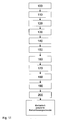
In Figur 11 ist ein beispielhaft ausgebildetes Verfahren zum gesicherten Einbau und/oder Austausch von Kernumfassungsschrauben zur Montage von Kernumfassungsblechen angegeben, wobei
- in einem ersten
Schritt 100 der Schraubenkopf einer vorhandenen,auszutauschenden Kernumfassungsschraube 4 freigelegt wird - in einem zweiten
Schritt 110 ein entsprechendes Profil, insbesondere ein Vierkant, zum Herausdrehen der vorhandenen Schraube 4 eingearbeitet - in einem dritten
Schritt 120 wenigstens zwei Löcher 50durch das Kernumfassungsblech 5 und/oder eine dahinter liegende Distanzscheibe 6 und/oder indie das Blech 5tragende Formrippe 2 gebohrt wird, - in einem vierten
Schritt 130je ein Sicherungsstift 52 in wenigstens zwei der Bohrungen 50 eingebracht wird,wobei die Sicherungsstifte 52 bezüglich ihrer Länge derart bemessen sind, dass siedas Kernumfassungsblech 5 nicht überragen beziehungsweise nicht überstehen, sondern insbesondere bündig mit diesem abschließen, - in
einem fünften Schritt 140die vorhandene Schraube 4 herausgedreht unddas vorhandene Sicherungsblech 7 abgezogen wird, - in
einem sechsten Schritt 150 wenigstens ein Führungsdorn indie Gewindebohrung 3der Formrippe 2 eingedreht wird,ineinem siebten Schritt 160 eine Nacharbeitung der Sitzfläche des Sicherungsbleches 7,40 durchgeführt wird, - in
einem achten 170 Schritt der Führungsdorn entfernt - in
einem neunten Schritt 180ein neues Sicherungsblech 40mit Innensenkung 42 und wenigstens einer Ausnehmung 46 zur mechanischen Sicherung der Kernumfassungsschraube 20 aufgesetzt wird, - in
einem zehnten Schritt 190eine Kernumfassungsschraube 20mit Anformung 28am Schraubenkopf 24 eingedreht wird, und - in
einem elften Schritt 200 die Anformung 28 mechanisch durch Krafteinwirkung derart verformt wird, dass sie zumindest anteilig in diewenigstens eine Ausnehmung 46 der Innensenkung des Sicherungsbleches eingreift, wodurch eine mechanische Sicherung der neuen Kernumfassungsschraube 20 gegen Verdrehen und/oder Losdrehen bewirkt wird.
- in a
first step 100, the screw head of an existingcore surround screw 4 to be replaced is uncovered - in a
second step 110, a corresponding profile, in particular a square, incorporated for unscrewing the existingscrew 4 - in a
third step 120, at least twoholes 50 are bored through thecore surround sheet 5 and / or aspacer 6 located behind it and / or into the formingrib 2 carrying thesheet metal 5, - in a
fourth step 130, arespective securing pin 52 is introduced into at least two of thebores 50, wherein the securing pins 52 are dimensioned with respect to their length such that they do not protrude beyond thecore enclosing plate 5 or, in particular, terminate flush therewith, - in a
fifth step 140, the existingscrew 4 is unscrewed and the existinglocking plate 7 is removed, - in a
sixth step 150 at least one guide pin is screwed into the threaded bore 3 of the shapedrib 2, in a seventh step 160 a reworking of the seat surface of thelocking plate - in an eighth 170 step the guide pin is removed
- in a
ninth step 180, anew locking plate 40 withinner countersink 42 and at least onerecess 46 for mechanical securing of thecore surround screw 20 is placed, - in a tenth step 190 a
Kernumfassungsschraube 20 withAnformung 28 is screwed to thescrew head 24, and - in an
eleventh step 200, theAnformung 28 is mechanically deformed by the action of force so that it at least partially engages the at least onerecess 46 of the inner countersinking of the lock plate, whereby a mechanical securing thenew Kernumfassungsschraube 20 against rotation and / or loosening is effected.
Das Eindrehen der Kernumfassungsschraube 20 erfolgt dabei drehmomentkontrolliert.
Alternativ können bei vorgenanntem Verfahren in Abhängigkeit der vorgefundenen Bedingungen einzelne Schritte auch unterbleiben oder zu einem anderen Zeitpunkt ausgeführt werden.The screwing in the
Alternatively, in the aforementioned method, depending on the conditions encountered, individual steps may also be omitted or carried out at a different time.
Sind keine Distanzscheiben vorhanden könnte beispielsweise das Einsetzen der Sicherungsstifte entfallen.If there are no spacers, for example, the insertion of the locking pins could be omitted.
Auch die Nachbearbeitung des Sitzes des Sicherungsbleches kann je nach Bedarf durchgeführt werden.The post-processing of the seat of the locking plate can be carried out as needed.
Claims (31)
Applications Claiming Priority (1)
| Application Number | Priority Date | Filing Date | Title |
|---|---|---|---|
| DE102006040272A DE102006040272A1 (en) | 2006-08-28 | 2006-08-28 | Core surround screw, assembly and method for secure installation and / or replacement of core containment screws |
Publications (2)
| Publication Number | Publication Date |
|---|---|
| EP1892428A1 true EP1892428A1 (en) | 2008-02-27 |
| EP1892428B1 EP1892428B1 (en) | 2012-02-08 |
Family
ID=38688120
Family Applications (1)
| Application Number | Title | Priority Date | Filing Date |
|---|---|---|---|
| EP07016525A Active EP1892428B1 (en) | 2006-08-28 | 2007-08-23 | Core perimeter screw, assembly and method for secure mounting and/or replacement of core perimeter screws |
Country Status (5)
| Country | Link |
|---|---|
| EP (1) | EP1892428B1 (en) |
| AT (1) | ATE544956T1 (en) |
| DE (1) | DE102006040272A1 (en) |
| RU (1) | RU2460906C2 (en) |
| UA (1) | UA97230C2 (en) |
Cited By (1)
| Publication number | Priority date | Publication date | Assignee | Title |
|---|---|---|---|---|
| WO2011037640A1 (en) * | 2009-09-25 | 2011-03-31 | Mclaren Performance Technologies, Inc. | Staked nut and flange for gear support |
Families Citing this family (2)
| Publication number | Priority date | Publication date | Assignee | Title |
|---|---|---|---|---|
| CN109901349A (en) * | 2017-12-11 | 2019-06-18 | 深圳光峰科技股份有限公司 | Lens adjustment and fixing structure and projection equipment |
| CN113048131A (en) * | 2019-12-27 | 2021-06-29 | 上海申标标准件有限公司 | Multipurpose bolt |
Citations (4)
| Publication number | Priority date | Publication date | Assignee | Title |
|---|---|---|---|---|
| DE3626338A1 (en) * | 1986-08-02 | 1988-02-11 | Bbc Reaktor Gmbh | Securing means for a fillister-head screw countersunk in a workpiece |
| EP0268817A1 (en) * | 1986-10-31 | 1988-06-01 | Siemens Aktiengesellschaft | Rotation-proof mechanical fastener and tool to secure the fastener |
| DE9013075U1 (en) * | 1990-09-14 | 1990-11-15 | ABB Reaktor GmbH, 6800 Mannheim | Locking device for a cap screw arranged in a countersunk hole of a component |
| US6164886A (en) * | 1999-06-01 | 2000-12-26 | Westinghouse Electric Company Llc | Bolt with integral locking member |
Family Cites Families (14)
| Publication number | Priority date | Publication date | Assignee | Title |
|---|---|---|---|---|
| FR493783A (en) * | 1918-12-12 | 1919-08-21 | Antoine Durand | Nut lock |
| DE2042312A1 (en) * | 1970-05-22 | 1971-12-02 | Bbc Brown Boveri & Cie | Securing for hexagon socket screws |
| DE2151932A1 (en) * | 1971-10-19 | 1973-04-26 | Zahnradfabrik Friedrichshafen | SCREW LOCKING |
| DE7603185U1 (en) * | 1976-02-05 | 1976-06-03 | Dynamit Nobel Ag, 5210 Troisdorf | FASTENING DISC FOR FASTENING LOOSELY INSTALLED SEALING MEMBRANES |
| DE2747994A1 (en) * | 1977-10-26 | 1979-05-03 | Kraftwerk Union Ag | ANTI-ROTATION FOR CYLINDER-HEAD SCREWS WITH MULTI-SOCKET AND TOOL FOR PLASTIC DEFORMING FOR SUCH ANTI-ROTATION |
| DE2903706A1 (en) * | 1979-01-31 | 1980-08-14 | Kraftwerk Union Ag | Locking cap for hexagonal bolt or nut - has flange screwing to support and collar deformable around bolt head to prevent rotation |
| SU812998A1 (en) * | 1979-04-09 | 1981-03-15 | Запорожский Проектно-Конструкторскийи Технологический Институт | Locking arrangement |
| DE8620893U1 (en) * | 1986-08-02 | 1986-11-27 | Abb Reaktor Gmbh, 68167 Mannheim | Locking device for a cylinder head screw countersunk in a workpiece |
| DE8710905U1 (en) * | 1987-08-10 | 1988-01-28 | Siemens AG, 1000 Berlin und 8000 München | Lockable container screw |
| DE9004238U1 (en) * | 1990-04-11 | 1991-08-08 | Waldemar Link GmbH & Co, 22339 Hamburg | Screw head with locking device |
| DE9013077U1 (en) * | 1990-09-14 | 1990-11-15 | ABB Reaktor GmbH, 6800 Mannheim | Locking device for a cap screw arranged in a countersunk hole of a component |
| DE4038507C1 (en) * | 1990-12-03 | 1992-06-17 | Abb Reaktor Gmbh, 6800 Mannheim, De | Device for remotely seating and tightening screw - includes ultrasound test head for measuring longitudinal expansion of screw shaft, used in nuclear reactor installation |
| DE19540743A1 (en) * | 1995-11-02 | 1997-05-07 | Asea Brown Boveri | Threadlocker |
| US6669419B1 (en) * | 2002-01-25 | 2003-12-30 | Radio Systems Corporation | Probe locking washer |
-
2006
- 2006-08-28 DE DE102006040272A patent/DE102006040272A1/en not_active Withdrawn
-
2007
- 2007-08-23 AT AT07016525T patent/ATE544956T1/en active
- 2007-08-23 EP EP07016525A patent/EP1892428B1/en active Active
- 2007-08-27 RU RU2007132229/12A patent/RU2460906C2/en active
- 2007-08-27 UA UAA200709679A patent/UA97230C2/en unknown
Patent Citations (4)
| Publication number | Priority date | Publication date | Assignee | Title |
|---|---|---|---|---|
| DE3626338A1 (en) * | 1986-08-02 | 1988-02-11 | Bbc Reaktor Gmbh | Securing means for a fillister-head screw countersunk in a workpiece |
| EP0268817A1 (en) * | 1986-10-31 | 1988-06-01 | Siemens Aktiengesellschaft | Rotation-proof mechanical fastener and tool to secure the fastener |
| DE9013075U1 (en) * | 1990-09-14 | 1990-11-15 | ABB Reaktor GmbH, 6800 Mannheim | Locking device for a cap screw arranged in a countersunk hole of a component |
| US6164886A (en) * | 1999-06-01 | 2000-12-26 | Westinghouse Electric Company Llc | Bolt with integral locking member |
Cited By (3)
| Publication number | Priority date | Publication date | Assignee | Title |
|---|---|---|---|---|
| WO2011037640A1 (en) * | 2009-09-25 | 2011-03-31 | Mclaren Performance Technologies, Inc. | Staked nut and flange for gear support |
| GB2485949A (en) * | 2009-09-25 | 2012-05-30 | Mclaren Performance Technologies Inc | Staked nut and flange for gear support |
| US8746100B2 (en) | 2009-09-25 | 2014-06-10 | Mclaren Performance Technologies Inc. | Staked nut and flange for gear support |
Also Published As
| Publication number | Publication date |
|---|---|
| UA97230C2 (en) | 2012-01-25 |
| ATE544956T1 (en) | 2012-02-15 |
| RU2460906C2 (en) | 2012-09-10 |
| EP1892428B1 (en) | 2012-02-08 |
| DE102006040272A1 (en) | 2008-03-06 |
| RU2007132229A (en) | 2009-03-10 |
Similar Documents
| Publication | Publication Date | Title |
|---|---|---|
| EP2788617B1 (en) | Rotor blade and connecting device | |
| DE102011054861A1 (en) | Fastening element with tolerance compensation function | |
| DE102011052610A1 (en) | Wind turbine anchor element | |
| DE102007018025A1 (en) | Wind turbine tower | |
| DE202010000868U1 (en) | Device for transporting and assembling wind turbines | |
| EP2163347A2 (en) | Variable adjustable device for extracting injection nozzles | |
| CH631789A5 (en) | TURNING LOCK FOR CYLINDER HEAD SCREWS WITH MULTI-SIDED INSIDE AND TOOL FOR PLASTICALLY DEFORMING FOR SUCH A TURNING LOCKING. | |
| EP2140968B1 (en) | Device and method for pressing in fastening elements | |
| EP1892428B1 (en) | Core perimeter screw, assembly and method for secure mounting and/or replacement of core perimeter screws | |
| EP3700033A1 (en) | Charging station assembly adapter, system comprising such an adapter and method for mounting a charging station | |
| DE202020103617U1 (en) | Anti-twist device | |
| EP0111145A2 (en) | Pressure vessel having a flange-like port | |
| DE102017103768A1 (en) | Fastening device and mounting assembly | |
| EP3974602B1 (en) | Coupling device for coupling tower segments of a tower of a wind turbine and assembly method therfore | |
| DE102015210516A1 (en) | Mounting system with thin shaft screw and securing element | |
| DE102018217276A1 (en) | Arrangement for fastening components to a cast metal component | |
| EP4048945A1 (en) | Supporting device, load body assembly and method for adjusting a supporting force acting on supporting devices of the load body assembly | |
| DE202021102497U1 (en) | Mold plate, threaded insert and mold plate arrangement | |
| EP3439784B1 (en) | Connecting assembly for connecting housing parts of a crusher | |
| WO2021160318A1 (en) | Removal apparatus for a component arrangement | |
| EP0962712A2 (en) | Radiator with angle compensator | |
| DE102019109904A1 (en) | Tower segment and method of building a tower | |
| DE202018106348U1 (en) | Nut and profile provided with such a nut | |
| DE10148244B4 (en) | Fuel element for a light water-moderated nuclear reactor | |
| EP4491815A1 (en) | Positioning device and method for connecting a second construction part to a first construction part |
Legal Events
| Date | Code | Title | Description |
|---|---|---|---|
| PUAI | Public reference made under article 153(3) epc to a published international application that has entered the european phase |
Free format text: ORIGINAL CODE: 0009012 |
|
| AK | Designated contracting states |
Kind code of ref document: A1 Designated state(s): AT BE BG CH CY CZ DE DK EE ES FI FR GB GR HU IE IS IT LI LT LU LV MC MT NL PL PT RO SE SI SK TR |
|
| AX | Request for extension of the european patent |
Extension state: AL BA HR MK YU |
|
| 17P | Request for examination filed |
Effective date: 20080222 |
|
| 17Q | First examination report despatched |
Effective date: 20080407 |
|
| R17C | First examination report despatched (corrected) |
Effective date: 20080905 |
|
| AKX | Designation fees paid |
Designated state(s): AT BE BG CH CY CZ DE DK EE ES FI FR GB GR HU IE IS IT LI LT LU LV MC MT NL PL PT RO SE SI SK TR |
|
| GRAP | Despatch of communication of intention to grant a patent |
Free format text: ORIGINAL CODE: EPIDOSNIGR1 |
|
| GRAS | Grant fee paid |
Free format text: ORIGINAL CODE: EPIDOSNIGR3 |
|
| GRAA | (expected) grant |
Free format text: ORIGINAL CODE: 0009210 |
|
| AK | Designated contracting states |
Kind code of ref document: B1 Designated state(s): AT BE BG CH CY CZ DE DK EE ES FI FR GB GR HU IE IS IT LI LT LU LV MC MT NL PL PT RO SE SI SK TR |
|
| REG | Reference to a national code |
Ref country code: GB Ref legal event code: FG4D Free format text: NOT ENGLISH |
|
| REG | Reference to a national code |
Ref country code: CH Ref legal event code: EP Ref country code: AT Ref legal event code: REF Ref document number: 544956 Country of ref document: AT Kind code of ref document: T Effective date: 20120215 |
|
| REG | Reference to a national code |
Ref country code: DE Ref legal event code: R096 Ref document number: 502007009234 Country of ref document: DE Effective date: 20120405 |
|
| REG | Reference to a national code |
Ref country code: NL Ref legal event code: VDEP Effective date: 20120208 |
|
| LTIE | Lt: invalidation of european patent or patent extension |
Effective date: 20120208 |
|
| PG25 | Lapsed in a contracting state [announced via postgrant information from national office to epo] |
Ref country code: IS Free format text: LAPSE BECAUSE OF FAILURE TO SUBMIT A TRANSLATION OF THE DESCRIPTION OR TO PAY THE FEE WITHIN THE PRESCRIBED TIME-LIMIT Effective date: 20120608 Ref country code: LT Free format text: LAPSE BECAUSE OF FAILURE TO SUBMIT A TRANSLATION OF THE DESCRIPTION OR TO PAY THE FEE WITHIN THE PRESCRIBED TIME-LIMIT Effective date: 20120208 Ref country code: NL Free format text: LAPSE BECAUSE OF FAILURE TO SUBMIT A TRANSLATION OF THE DESCRIPTION OR TO PAY THE FEE WITHIN THE PRESCRIBED TIME-LIMIT Effective date: 20120208 |
|
| REG | Reference to a national code |
Ref country code: SK Ref legal event code: T3 Ref document number: E 11782 Country of ref document: SK |
|
| REG | Reference to a national code |
Ref country code: IE Ref legal event code: FD4D |
|
| PG25 | Lapsed in a contracting state [announced via postgrant information from national office to epo] |
Ref country code: PT Free format text: LAPSE BECAUSE OF FAILURE TO SUBMIT A TRANSLATION OF THE DESCRIPTION OR TO PAY THE FEE WITHIN THE PRESCRIBED TIME-LIMIT Effective date: 20120608 Ref country code: PL Free format text: LAPSE BECAUSE OF FAILURE TO SUBMIT A TRANSLATION OF THE DESCRIPTION OR TO PAY THE FEE WITHIN THE PRESCRIBED TIME-LIMIT Effective date: 20120208 Ref country code: GR Free format text: LAPSE BECAUSE OF FAILURE TO SUBMIT A TRANSLATION OF THE DESCRIPTION OR TO PAY THE FEE WITHIN THE PRESCRIBED TIME-LIMIT Effective date: 20120509 Ref country code: LV Free format text: LAPSE BECAUSE OF FAILURE TO SUBMIT A TRANSLATION OF THE DESCRIPTION OR TO PAY THE FEE WITHIN THE PRESCRIBED TIME-LIMIT Effective date: 20120208 |
|
| PG25 | Lapsed in a contracting state [announced via postgrant information from national office to epo] |
Ref country code: CY Free format text: LAPSE BECAUSE OF FAILURE TO SUBMIT A TRANSLATION OF THE DESCRIPTION OR TO PAY THE FEE WITHIN THE PRESCRIBED TIME-LIMIT Effective date: 20120208 |
|
| PG25 | Lapsed in a contracting state [announced via postgrant information from national office to epo] |
Ref country code: CZ Free format text: LAPSE BECAUSE OF FAILURE TO SUBMIT A TRANSLATION OF THE DESCRIPTION OR TO PAY THE FEE WITHIN THE PRESCRIBED TIME-LIMIT Effective date: 20120208 Ref country code: IE Free format text: LAPSE BECAUSE OF FAILURE TO SUBMIT A TRANSLATION OF THE DESCRIPTION OR TO PAY THE FEE WITHIN THE PRESCRIBED TIME-LIMIT Effective date: 20120208 Ref country code: DK Free format text: LAPSE BECAUSE OF FAILURE TO SUBMIT A TRANSLATION OF THE DESCRIPTION OR TO PAY THE FEE WITHIN THE PRESCRIBED TIME-LIMIT Effective date: 20120208 Ref country code: SE Free format text: LAPSE BECAUSE OF FAILURE TO SUBMIT A TRANSLATION OF THE DESCRIPTION OR TO PAY THE FEE WITHIN THE PRESCRIBED TIME-LIMIT Effective date: 20120208 Ref country code: RO Free format text: LAPSE BECAUSE OF FAILURE TO SUBMIT A TRANSLATION OF THE DESCRIPTION OR TO PAY THE FEE WITHIN THE PRESCRIBED TIME-LIMIT Effective date: 20120208 Ref country code: EE Free format text: LAPSE BECAUSE OF FAILURE TO SUBMIT A TRANSLATION OF THE DESCRIPTION OR TO PAY THE FEE WITHIN THE PRESCRIBED TIME-LIMIT Effective date: 20120208 Ref country code: SI Free format text: LAPSE BECAUSE OF FAILURE TO SUBMIT A TRANSLATION OF THE DESCRIPTION OR TO PAY THE FEE WITHIN THE PRESCRIBED TIME-LIMIT Effective date: 20120208 |
|
| PG25 | Lapsed in a contracting state [announced via postgrant information from national office to epo] |
Ref country code: IT Free format text: LAPSE BECAUSE OF FAILURE TO SUBMIT A TRANSLATION OF THE DESCRIPTION OR TO PAY THE FEE WITHIN THE PRESCRIBED TIME-LIMIT Effective date: 20120208 |
|
| PLBE | No opposition filed within time limit |
Free format text: ORIGINAL CODE: 0009261 |
|
| STAA | Information on the status of an ep patent application or granted ep patent |
Free format text: STATUS: NO OPPOSITION FILED WITHIN TIME LIMIT |
|
| 26N | No opposition filed |
Effective date: 20121109 |
|
| BERE | Be: lapsed |
Owner name: WESTINGHOUSE ELECTRIC GERMANY G.M.B.H. Effective date: 20120831 |
|
| REG | Reference to a national code |
Ref country code: DE Ref legal event code: R097 Ref document number: 502007009234 Country of ref document: DE Effective date: 20121109 |
|
| REG | Reference to a national code |
Ref country code: CH Ref legal event code: PL |
|
| PG25 | Lapsed in a contracting state [announced via postgrant information from national office to epo] |
Ref country code: MC Free format text: LAPSE BECAUSE OF NON-PAYMENT OF DUE FEES Effective date: 20120831 |
|
| GBPC | Gb: european patent ceased through non-payment of renewal fee |
Effective date: 20120823 |
|
| PG25 | Lapsed in a contracting state [announced via postgrant information from national office to epo] |
Ref country code: CH Free format text: LAPSE BECAUSE OF NON-PAYMENT OF DUE FEES Effective date: 20120831 Ref country code: ES Free format text: LAPSE BECAUSE OF FAILURE TO SUBMIT A TRANSLATION OF THE DESCRIPTION OR TO PAY THE FEE WITHIN THE PRESCRIBED TIME-LIMIT Effective date: 20120519 Ref country code: LI Free format text: LAPSE BECAUSE OF NON-PAYMENT OF DUE FEES Effective date: 20120831 |
|
| REG | Reference to a national code |
Ref country code: FR Ref legal event code: ST Effective date: 20130430 |
|
| PG25 | Lapsed in a contracting state [announced via postgrant information from national office to epo] |
Ref country code: BE Free format text: LAPSE BECAUSE OF NON-PAYMENT OF DUE FEES Effective date: 20120831 |
|
| REG | Reference to a national code |
Ref country code: HU Ref legal event code: AG4A Ref document number: E015747 Country of ref document: HU |
|
| PG25 | Lapsed in a contracting state [announced via postgrant information from national office to epo] |
Ref country code: GB Free format text: LAPSE BECAUSE OF NON-PAYMENT OF DUE FEES Effective date: 20120823 Ref country code: BG Free format text: LAPSE BECAUSE OF FAILURE TO SUBMIT A TRANSLATION OF THE DESCRIPTION OR TO PAY THE FEE WITHIN THE PRESCRIBED TIME-LIMIT Effective date: 20120508 |
|
| PG25 | Lapsed in a contracting state [announced via postgrant information from national office to epo] |
Ref country code: FR Free format text: LAPSE BECAUSE OF NON-PAYMENT OF DUE FEES Effective date: 20120831 |
|
| REG | Reference to a national code |
Ref country code: AT Ref legal event code: MM01 Ref document number: 544956 Country of ref document: AT Kind code of ref document: T Effective date: 20120831 |
|
| PG25 | Lapsed in a contracting state [announced via postgrant information from national office to epo] |
Ref country code: AT Free format text: LAPSE BECAUSE OF NON-PAYMENT OF DUE FEES Effective date: 20120831 |
|
| PG25 | Lapsed in a contracting state [announced via postgrant information from national office to epo] |
Ref country code: MT Free format text: LAPSE BECAUSE OF FAILURE TO SUBMIT A TRANSLATION OF THE DESCRIPTION OR TO PAY THE FEE WITHIN THE PRESCRIBED TIME-LIMIT Effective date: 20120208 |
|
| PG25 | Lapsed in a contracting state [announced via postgrant information from national office to epo] |
Ref country code: TR Free format text: LAPSE BECAUSE OF FAILURE TO SUBMIT A TRANSLATION OF THE DESCRIPTION OR TO PAY THE FEE WITHIN THE PRESCRIBED TIME-LIMIT Effective date: 20120208 |
|
| PG25 | Lapsed in a contracting state [announced via postgrant information from national office to epo] |
Ref country code: LU Free format text: LAPSE BECAUSE OF NON-PAYMENT OF DUE FEES Effective date: 20120823 |
|
| PGFP | Annual fee paid to national office [announced via postgrant information from national office to epo] |
Ref country code: HU Payment date: 20251028 Year of fee payment: 19 |
|
| PGFP | Annual fee paid to national office [announced via postgrant information from national office to epo] |
Ref country code: DE Payment date: 20251010 Year of fee payment: 19 |
|
| PGFP | Annual fee paid to national office [announced via postgrant information from national office to epo] |
Ref country code: FI Payment date: 20251010 Year of fee payment: 19 |
|
| PGFP | Annual fee paid to national office [announced via postgrant information from national office to epo] |
Ref country code: SK Payment date: 20251023 Year of fee payment: 19 |