EP1892418A2 - Machine à engrenage - Google Patents
Machine à engrenage Download PDFInfo
- Publication number
- EP1892418A2 EP1892418A2 EP07015680A EP07015680A EP1892418A2 EP 1892418 A2 EP1892418 A2 EP 1892418A2 EP 07015680 A EP07015680 A EP 07015680A EP 07015680 A EP07015680 A EP 07015680A EP 1892418 A2 EP1892418 A2 EP 1892418A2
- Authority
- EP
- European Patent Office
- Prior art keywords
- housing
- bearing
- shaft
- gear
- drive shaft
- Prior art date
- Legal status (The legal status is an assumption and is not a legal conclusion. Google has not performed a legal analysis and makes no representation as to the accuracy of the status listed.)
- Withdrawn
Links
Images


Classifications
-
- F—MECHANICAL ENGINEERING; LIGHTING; HEATING; WEAPONS; BLASTING
- F04—POSITIVE - DISPLACEMENT MACHINES FOR LIQUIDS; PUMPS FOR LIQUIDS OR ELASTIC FLUIDS
- F04C—ROTARY-PISTON, OR OSCILLATING-PISTON, POSITIVE-DISPLACEMENT MACHINES FOR LIQUIDS; ROTARY-PISTON, OR OSCILLATING-PISTON, POSITIVE-DISPLACEMENT PUMPS
- F04C15/00—Component parts, details or accessories of machines, pumps or pumping installations, not provided for in groups F04C2/00 - F04C14/00
- F04C15/0003—Sealing arrangements in rotary-piston machines or pumps
- F04C15/0034—Sealing arrangements in rotary-piston machines or pumps for other than the working fluid, i.e. the sealing arrangements are not between working chambers of the machine
- F04C15/0038—Shaft sealings specially adapted for rotary-piston machines or pumps
-
- F—MECHANICAL ENGINEERING; LIGHTING; HEATING; WEAPONS; BLASTING
- F04—POSITIVE - DISPLACEMENT MACHINES FOR LIQUIDS; PUMPS FOR LIQUIDS OR ELASTIC FLUIDS
- F04C—ROTARY-PISTON, OR OSCILLATING-PISTON, POSITIVE-DISPLACEMENT MACHINES FOR LIQUIDS; ROTARY-PISTON, OR OSCILLATING-PISTON, POSITIVE-DISPLACEMENT PUMPS
- F04C13/00—Adaptations of machines or pumps for special use, e.g. for extremely high pressures
- F04C13/001—Pumps for particular liquids
-
- F—MECHANICAL ENGINEERING; LIGHTING; HEATING; WEAPONS; BLASTING
- F16—ENGINEERING ELEMENTS AND UNITS; GENERAL MEASURES FOR PRODUCING AND MAINTAINING EFFECTIVE FUNCTIONING OF MACHINES OR INSTALLATIONS; THERMAL INSULATION IN GENERAL
- F16C—SHAFTS; FLEXIBLE SHAFTS; ELEMENTS OR CRANKSHAFT MECHANISMS; ROTARY BODIES OTHER THAN GEARING ELEMENTS; BEARINGS
- F16C33/00—Parts of bearings; Special methods for making bearings or parts thereof
- F16C33/02—Parts of sliding-contact bearings
- F16C33/04—Brasses; Bushes; Linings
- F16C33/20—Sliding surface consisting mainly of plastics
-
- F—MECHANICAL ENGINEERING; LIGHTING; HEATING; WEAPONS; BLASTING
- F04—POSITIVE - DISPLACEMENT MACHINES FOR LIQUIDS; PUMPS FOR LIQUIDS OR ELASTIC FLUIDS
- F04C—ROTARY-PISTON, OR OSCILLATING-PISTON, POSITIVE-DISPLACEMENT MACHINES FOR LIQUIDS; ROTARY-PISTON, OR OSCILLATING-PISTON, POSITIVE-DISPLACEMENT PUMPS
- F04C2/00—Rotary-piston machines or pumps
- F04C2/08—Rotary-piston machines or pumps of intermeshing-engagement type, i.e. with engagement of co-operating members similar to that of toothed gearing
- F04C2/12—Rotary-piston machines or pumps of intermeshing-engagement type, i.e. with engagement of co-operating members similar to that of toothed gearing of other than internal-axis type
- F04C2/14—Rotary-piston machines or pumps of intermeshing-engagement type, i.e. with engagement of co-operating members similar to that of toothed gearing of other than internal-axis type with toothed rotary pistons
- F04C2/18—Rotary-piston machines or pumps of intermeshing-engagement type, i.e. with engagement of co-operating members similar to that of toothed gearing of other than internal-axis type with toothed rotary pistons with similar tooth forms
-
- F—MECHANICAL ENGINEERING; LIGHTING; HEATING; WEAPONS; BLASTING
- F04—POSITIVE - DISPLACEMENT MACHINES FOR LIQUIDS; PUMPS FOR LIQUIDS OR ELASTIC FLUIDS
- F04C—ROTARY-PISTON, OR OSCILLATING-PISTON, POSITIVE-DISPLACEMENT MACHINES FOR LIQUIDS; ROTARY-PISTON, OR OSCILLATING-PISTON, POSITIVE-DISPLACEMENT PUMPS
- F04C2240/00—Components
- F04C2240/50—Bearings
-
- F—MECHANICAL ENGINEERING; LIGHTING; HEATING; WEAPONS; BLASTING
- F05—INDEXING SCHEMES RELATING TO ENGINES OR PUMPS IN VARIOUS SUBCLASSES OF CLASSES F01-F04
- F05C—INDEXING SCHEME RELATING TO MATERIALS, MATERIAL PROPERTIES OR MATERIAL CHARACTERISTICS FOR MACHINES, ENGINES OR PUMPS OTHER THAN NON-POSITIVE-DISPLACEMENT MACHINES OR ENGINES
- F05C2225/00—Synthetic polymers, e.g. plastics; Rubber
-
- F—MECHANICAL ENGINEERING; LIGHTING; HEATING; WEAPONS; BLASTING
- F16—ENGINEERING ELEMENTS AND UNITS; GENERAL MEASURES FOR PRODUCING AND MAINTAINING EFFECTIVE FUNCTIONING OF MACHINES OR INSTALLATIONS; THERMAL INSULATION IN GENERAL
- F16C—SHAFTS; FLEXIBLE SHAFTS; ELEMENTS OR CRANKSHAFT MECHANISMS; ROTARY BODIES OTHER THAN GEARING ELEMENTS; BEARINGS
- F16C2208/00—Plastics; Synthetic resins, e.g. rubbers
- F16C2208/20—Thermoplastic resins
- F16C2208/30—Fluoropolymers
- F16C2208/32—Polytetrafluorethylene [PTFE]
-
- F—MECHANICAL ENGINEERING; LIGHTING; HEATING; WEAPONS; BLASTING
- F16—ENGINEERING ELEMENTS AND UNITS; GENERAL MEASURES FOR PRODUCING AND MAINTAINING EFFECTIVE FUNCTIONING OF MACHINES OR INSTALLATIONS; THERMAL INSULATION IN GENERAL
- F16C—SHAFTS; FLEXIBLE SHAFTS; ELEMENTS OR CRANKSHAFT MECHANISMS; ROTARY BODIES OTHER THAN GEARING ELEMENTS; BEARINGS
- F16C2208/00—Plastics; Synthetic resins, e.g. rubbers
- F16C2208/20—Thermoplastic resins
- F16C2208/60—Polyamides [PA]
-
- F—MECHANICAL ENGINEERING; LIGHTING; HEATING; WEAPONS; BLASTING
- F16—ENGINEERING ELEMENTS AND UNITS; GENERAL MEASURES FOR PRODUCING AND MAINTAINING EFFECTIVE FUNCTIONING OF MACHINES OR INSTALLATIONS; THERMAL INSULATION IN GENERAL
- F16C—SHAFTS; FLEXIBLE SHAFTS; ELEMENTS OR CRANKSHAFT MECHANISMS; ROTARY BODIES OTHER THAN GEARING ELEMENTS; BEARINGS
- F16C2208/00—Plastics; Synthetic resins, e.g. rubbers
- F16C2208/20—Thermoplastic resins
- F16C2208/66—Acetals, e.g. polyoxymethylene [POM]
-
- F—MECHANICAL ENGINEERING; LIGHTING; HEATING; WEAPONS; BLASTING
- F16—ENGINEERING ELEMENTS AND UNITS; GENERAL MEASURES FOR PRODUCING AND MAINTAINING EFFECTIVE FUNCTIONING OF MACHINES OR INSTALLATIONS; THERMAL INSULATION IN GENERAL
- F16C—SHAFTS; FLEXIBLE SHAFTS; ELEMENTS OR CRANKSHAFT MECHANISMS; ROTARY BODIES OTHER THAN GEARING ELEMENTS; BEARINGS
- F16C2208/00—Plastics; Synthetic resins, e.g. rubbers
- F16C2208/20—Thermoplastic resins
- F16C2208/76—Polyolefins, e.g. polyproylene [PP]
- F16C2208/78—Polyethylene [PE], e.g. ultra-high molecular weight polyethylene [UHMWPE]
-
- F—MECHANICAL ENGINEERING; LIGHTING; HEATING; WEAPONS; BLASTING
- F16—ENGINEERING ELEMENTS AND UNITS; GENERAL MEASURES FOR PRODUCING AND MAINTAINING EFFECTIVE FUNCTIONING OF MACHINES OR INSTALLATIONS; THERMAL INSULATION IN GENERAL
- F16C—SHAFTS; FLEXIBLE SHAFTS; ELEMENTS OR CRANKSHAFT MECHANISMS; ROTARY BODIES OTHER THAN GEARING ELEMENTS; BEARINGS
- F16C2240/00—Specified values or numerical ranges of parameters; Relations between them
- F16C2240/40—Linear dimensions, e.g. length, radius, thickness, gap
- F16C2240/60—Thickness, e.g. thickness of coatings
Definitions
- the invention relates to a gear machine, in particular gear pump, with a housing and an engine arranged in the housing of at least two meshing gears for conveying and / or metering a fluid, in particular a paint, a wax, a solvent, a hardener, a sealant or dergl.
- a gear machine in particular gear pump
- a housing and an engine arranged in the housing of at least two meshing gears for conveying and / or metering a fluid, in particular a paint, a wax, a solvent, a hardener, a sealant or dergl.
- gear machines are used for example as gear pumps for metering fluids, such as paints, waxes, solvents, sealants, hardeners or the like., In the automotive industry. These gear machines are usually attached to robot arms, which move the respective gear pump to the place where the fluid is to be applied. For this purpose, it is advantageous if the gear pumps have a low weight and occupy a small volume, so that the robot arm must be built less stable and the gear pump can also reach places that are difficult to access.
- Known gear pumps have two mutually meshing gears, wherein a first gear is secured against rotation with a drive shaft.
- the arranged in a housing gears promote and meter the fluid, wherein the flow rate is proportional to the angle of rotation of the gears.
- the drive shaft is on the side where the shaft journal out of the housing protrudes, connected to the respective drive motor.
- the drive shaft is usually mounted at the shaft journal end in a bearing and at the opposite end in a plain bearing, for which a metallic bushing is used in known gear pumps.
- gear pumps operate at speeds between about 60 to 80 revolutions per minute and have at a delivery volume of about 6 cm 3 per revolution about a weight of 5 to 7 kg.
- These bearings with metal bushings do not allow about 80 revolutions per minute significantly exceeding speeds, so that a gear pump to achieve a higher flow rate, must be equipped with larger gears.
- these larger gears require a higher weight and a larger volume of the gear pump.
- Object of the present invention is in contrast to provide a gear machine of the type mentioned above, which avoids penetration of the paint in the camp, is less expensive and more durable and is built smaller with the same volume and has a lower weight.
- the housing is sealed to the drive shaft in the direction of the shaft journal end of the drive shaft by means of a guide shaft seal, which is arranged inside in front of the bearing designed as a rolling bearing and which has at least one sealing lip, and that the bearing bush has an inner surface made of plastic.
- the guide shaft seal arranged in front of the roller bearing prevents penetration of the paint located inside the housing into the outer roller bearing. In addition, the tightening of the spring and the replacement of the seals is required only at longer intervals.
- the guide shaft seal also serves to guide the drive shaft in the housing in addition to the storage by the rolling bearing.
- the drive shaft forms a unit with the rolling bearing and the guide shaft seal, which can be assembled and disassembled together.
- the drive shaft must be pulled out of the housing and possibly replaced by a new shaft unit. Possibly. the drive shaft must be lapped.
- the advantageous arrangement of the guide shaft seal lying inside in front of the roller bearing makes it possible that the first sealing lip of the guide shaft seal, which is arranged on the engine-side end of the guide shaft seal, can be rinsed in a rinsing process by means of a rinsing fluid.
- the inventive structure of the gear machine ensures that the gear machine can be operated at higher speeds, ie at more than 300 revolutions per minute and thus can be built smaller at the same delivery rates. Consequently, the gear pump used in places that are more difficult to access.
- the gear machine according to the invention also has a smaller weight and is thus easier to handle in robot operation.
- a gear pump according to the invention has a weight of about 2 kg at a speed of 200 revolutions per minute and a delivery volume of 6 cm 3 .
- the guide shaft seal consists of a polyethylene (PE), in particular a UHMW-PE (ultra-high molecular weight PE), or a PTFE or a compound of one or more of these materials, since a sealing lip made of these materials is easy to manufacture.
- PE polyethylene
- UHMW-PE ultra-high molecular weight PE
- PTFE PTFE
- a sealing lip made of these materials is easy to manufacture.
- the UHMW-PE has the advantage that this material is particularly highly compressed.
- the plastic which is arranged on the inner surface of the bearing bush, consists of a solvent-resistant plastic which does not contain any substances which wetting the paint wetting properties (LABS-free), for example of PTFE (polytetrafluoroethylene) and / or of a PE (polyethylene) , preferably from a UHMW-PE, and / or from a PA (polyamide) and / or a POM (polyacetal) and / or from a compound with one or more of these materials, preferably with glass fibers, particularly preferably from a PTFE compound.
- These plastics are particularly suitable for high speeds and, in the case of PTFE, particularly resistant to heat and solvents.
- the thickness of the plastic layer forming the inner surface of the bearing bush is at least 0.5 mm, preferably at least 1.5 mm, particularly preferably at least 3 mm. These layer thicknesses ensure that the bearing bush is sufficiently rigid.
- the housing for cleaning its interior, the recorded therein, at least two intermeshing Gears and these supporting shafts or axles on at least one flushing passage which extends from an inlet opening to an outlet opening and extends through the interior of the housing.
- the task of this flushing channel is to clean the interior of the housing, the gears and the shafts or axles during paint changes.
- the flushing channel extends in regions through at least one of the shafts or axles, in regions by a helically around at least one of the shafts or axles circumferential groove and partially through the space formed between the gears and the housing space. This arrangement of the flushing channel ensures that the entire interior of the housing can be flushed quickly and efficiently.
- the flushing channel has a second input opening in an axis fixed in the housing, on which the at least one second gearwheel is mounted.
- the bearing bush with the surface of plastic with a ball bearing as a rolling bearing for the drive shaft (2-point mounting)
- the axial thrust of the drive can be collected.
- a reduced drive torque is achieved by this combination.
- the ball bearing is preferably made of stainless steel and is disposed at the shaft journal end of the drive shaft. It also allows the drive shaft to be turned both left and right.
- the first gear is connected to the drive shaft via a flushable feather key, so that the feather key of ink residues or the like can also be cleaned.
- this design allows a simpler seal replacement without pump disassembly. For this purpose, after releasing the cover of the ball bearing, the shaft with the guide shaft seal and the ball bearing, which preferably form a unit, pulled together from the corresponding bore of the first gear and made a seal change.
- the housing is at least a bearing plate, a center plate and a shaft journal side plate, wherein the bearing plate is disposed adjacent to the middle plate and the middle plate adjacent the shaft journal side plate and wherein the at least two gears of the engine are arranged in a corresponding recess of the center plate.
- An adjustment of the delivery volume of the gear pump is thereby very easy, since only the center plate with the gears and the corresponding shafts and axles must be replaced.
- an O-ring seal for sealing the respective plate gap is provided between the bearing plate and the middle plate and between the middle plate and the shaft journal-side plate.
- the gear machine also has at least one dowel pin, preferably at least two dowel pins, through which the center plate, the bearing plate and the shaft journal-side plate are aligned in their position relative to each other.
- at least one of the said plates to the position of the dowel pins fittingly arranged mating sleeves.
- the DLC or ADLC coating is made of (amorphous) carbon and is therefore very hard.
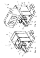
- Fig. 1 a the housing 2 of a gear pump 1 according to the invention is shown, which is composed of a shaft journal-side plate 5, a center plate 6 and a bearing plate 7.
- the shaft journal-side plate 5 of the housing 2 is connected to a holder 9, which is designed substantially plate-shaped.
- the holder 9 allows by their design, the assembly of the smaller gear pump to systems that were equipped with conventional gear pumps.
- a bearing plate 11 is arranged, in which the drive shaft 13 is mounted in a ball bearing 15.
- the drive motor (not shown) is connected to the drive shaft 13 of the gear pump 1.
- openings 20, 21 are provided for the supply and removal of the paint or a rinsing agent.
- a connection plate 25 which was used for conventional, larger-built gear pumps, with the openings 20, 21 are connected.
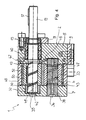
- the engine of the gear pump in the illustrated embodiment form a first gear 50 and a second gear 53, which are arranged in the housing 2 formed from the bearing plate 7, the center plate 6 and the shaft journal-side plate 5.
- the first gear 50 is connected to the drive shaft 13 against rotation by means of a flushable key 52.
- the first gear 50 and the second gear 53 mesh with each other and serve to convey the varnish in a preset amount according to the rotational angle of the drive shaft 13 and the gears 50, 53, respectively.
- a hollow cylindrical bearing element 32 is provided in a corresponding recess of the bearing plate 7 is provided, which forms a sliding bearing for the drive shaft 13.
- This bearing element 32 is replaceable and is preferably at least partially made of a solvent-resistant Plastic, preferably made of PTFE, a PTFE compound, PE, PA and / or POM and / or one or more of the aforementioned plastics reinforced by glass fibers.
- the bearing element 32 consists of a glass fiber reinforced PTFE.
- the shaft journal-side end 19 of the drive shaft 13 provided slide bearing can also be formed from a corresponding cylindrical recess in the bearing plate 7, which at all the bearing inner surfaces forming a solvent-resistant plastic coating, preferably a PTFE or PTFE compound coating , Particularly preferably reinforced by glass fibers.
- the drive shaft 13 is supported by the bearing member 32 and the ball bearing 15. Based on a double arrow 27 is shown in the illustrated in Fig. 2 front view of the housing 2 with the bearing disc 11 that the gear pump according to the invention by this combination of ball bearings 15 and plastic bearing member 32 allows rotation of the drive shaft 13 both left and right.
- the housing interior is sealed to the drive shaft 13 to the outside by means of a hollow cylindrical guide shaft seal 60, which is arranged in the direction of the shaft end 19 of the drive shaft 13 inside the housing 2 in front of the ball bearing 15. On the inner circumferential surface of the guide shaft seal 60, this has a first sealing lip 61 and a second sealing lip 62, which are arranged one after the other in the longitudinal direction of the guide shaft seal 60.
- the first sealing lip 61 is arranged directly on the engine-side end of the inner circumferential surface of the guide shaft seal 60.
- the lacquer or the flushing fluid can thus penetrate to the first sealing lip 61 in the gap between the drive shaft 13 and guide shaft seal 60, so that the first sealing lip 61 is flushed by the flushing fluid.
- the Guide shaft seal 60 is inserted into a corresponding recess of the shaft journal-side plate 5 and sealed against this by means of three also in the longitudinal direction of the guide shaft seal 60 successively arranged O-rings 64, which lie on the outer surface of the guide shaft seal 60 in each case a corresponding groove.
- the guide shaft seal 60 is preferably made of a polyethylene, more preferably of a UHMW-PE (ultra-high molecular weight polyethylene), which is particularly highly densified.
- a first opening 35 and a second opening 36 are provided as inputs for a flushing fluid.
- the first opening 35 is arranged where in the bearing plate 7, the drive shaft 13 ends.
- the second opening 36 is disposed in the end of the axle 38 parallel to the end 30 of the drive shaft 13.
- the end face of the bearing plate 7 further comprises between the first opening 35 and the second opening 36 side by side arranged bypass ports 40.
- the rinsing fluid used is preferably water-soluble rinsing agents, for example demineralized water (demineralized water).
- Exits for the flushing fluid form the arranged on the upper end face of the shaft journal-side plate 5 ports 20, 21st
- the first opening 35 in the bearing plate 7 can be used as an inlet for the flushing fluid and the second opening 36 in the bearing plate 7 as an exit for the flushing fluid or vice versa for a faster flushing process.
- the flushing channel is also partially formed by a helically around the drive shaft 13 circumferential groove 42 and a helical around the fixed axis 38 circumferential groove 43.
- the flushing channel further extends through a first along the longitudinal axis of the drive shaft 13 extending and then perpendicular to the longitudinal axis extending channel 45.
- the axis 38 has a channel belonging to the first channel 46, which is arranged at the end of the axis at which the opening 36 of the provided, and a second channel 47 at the opposite end of the axis 38 on.
- the channels 46, 47 extend, starting from the respective end of the axle 38, first along the center line of the axle 38 and then transversely thereto.
- Another portion of the scavenger passage is through a channel 48 in the shaft journal-side plate 5 and through the spaces between the gears 50, 53, between the second gear 53 and the axis 38, between the first gear 50 and the drive shaft 13 and between the gears 50th , 53, the drive shaft 13, the axis 38 and the housing from the plates 5,6,7 formed.
- the housing 2, the shaft journal-side plate 5, the middle plate 6, the bearing plate 7, the drive shaft 13 and the shaft 38 are made of stainless steel and are DLC or ADLC coated.
- the bearing plate 7 at least two dowel pins, not shown, and the shaft journal-side plate 5 and the middle plate 6 each have a corresponding number of mating sleeves, through which the plates 5, 6, 7 are aligned by means of the dowel pins in position relative to each other.
- the interior of the housing 2 is sealed between the shaft journal-side plate 5 and center plate by an O-ring 67 and between the middle plate 6 and bearing plate 7 by an O-ring 68.
- the gear machine can for example be arranged directly on the atomizer head in the robot arm.
- the gear machine is driven in this case by the oil, which also serves to actuate the robot arm.
- the gear machine can be arranged in or on a spray gun housing.
Landscapes
- Engineering & Computer Science (AREA)
- General Engineering & Computer Science (AREA)
- Mechanical Engineering (AREA)
- Rotary Pumps (AREA)
- Details And Applications Of Rotary Liquid Pumps (AREA)
Applications Claiming Priority (2)
| Application Number | Priority Date | Filing Date | Title |
|---|---|---|---|
| DE200620012407 DE202006012407U1 (de) | 2006-08-12 | 2006-08-12 | Zahnradmaschine |
| DE200620012409 DE202006012409U1 (de) | 2006-08-12 | 2006-08-12 | Zahnradmaschine |
Publications (2)
| Publication Number | Publication Date |
|---|---|
| EP1892418A2 true EP1892418A2 (fr) | 2008-02-27 |
| EP1892418A3 EP1892418A3 (fr) | 2014-08-27 |
Family
ID=38656999
Family Applications (1)
| Application Number | Title | Priority Date | Filing Date |
|---|---|---|---|
| EP07015680.7A Withdrawn EP1892418A3 (fr) | 2006-08-12 | 2007-08-09 | Machine à engrenage |
Country Status (1)
| Country | Link |
|---|---|
| EP (1) | EP1892418A3 (fr) |
Cited By (3)
| Publication number | Priority date | Publication date | Assignee | Title |
|---|---|---|---|---|
| DE102011016611A1 (de) | 2011-04-01 | 2012-10-04 | Technische Universität Dresden | Gleitsystem |
| EP2565454A1 (fr) * | 2011-09-02 | 2013-03-06 | Watson Marlow GmbH MasoSine | Pompe à déplacement rotatif pour pomper des matériaux fluides ayant une haute viscosité |
| DE102021004717A1 (de) | 2021-09-20 | 2023-03-23 | Oerlikon Textile Gmbh & Co. Kg | Dosierpumpe zum Fördern von abrasiven Fluiden |
Family Cites Families (6)
| Publication number | Priority date | Publication date | Assignee | Title |
|---|---|---|---|---|
| FR2133280A5 (en) * | 1971-04-15 | 1972-11-24 | Hydroperfect Internal | Bearing bushes - for hydraulic motors |
| US4057375A (en) * | 1976-10-22 | 1977-11-08 | Nachtrieb Paul W | Pump structure |
| DE3045192C2 (de) * | 1980-12-01 | 1983-10-27 | Fresenius AG, 6380 Bad Homburg | Zahnradpumpe |
| DE10138058A1 (de) * | 2001-08-03 | 2003-02-27 | Federal Mogul Deva Gmbh | Vollmateriallager und Verfahren zu seiner Herstellung |
| US20040070152A1 (en) * | 2002-08-05 | 2004-04-15 | Oehman Robert E. | Ventilated pump shaft seal |
| DE102004052558A1 (de) * | 2004-10-29 | 2006-05-04 | Saurer Gmbh & Co. Kg | Zahnradpumpe |
-
2007
- 2007-08-09 EP EP07015680.7A patent/EP1892418A3/fr not_active Withdrawn
Cited By (6)
| Publication number | Priority date | Publication date | Assignee | Title |
|---|---|---|---|---|
| DE102011016611A1 (de) | 2011-04-01 | 2012-10-04 | Technische Universität Dresden | Gleitsystem |
| WO2012130865A1 (fr) | 2011-04-01 | 2012-10-04 | Fraunhofer-Gesellschaft zur Förderung der angewandten Forschung e.V. | Système coulissant |
| US9267542B2 (en) | 2011-04-01 | 2016-02-23 | Fraunhofer-Gesellschaft zur Förderung der angewandten Forschung e.V. | System of sliding elements |
| EP2565454A1 (fr) * | 2011-09-02 | 2013-03-06 | Watson Marlow GmbH MasoSine | Pompe à déplacement rotatif pour pomper des matériaux fluides ayant une haute viscosité |
| WO2013030025A3 (fr) * | 2011-09-02 | 2013-12-19 | Watson-Marlow Gmbh | Pompe volumétrique rotative pour le pompage de matières visqueuses fluides |
| DE102021004717A1 (de) | 2021-09-20 | 2023-03-23 | Oerlikon Textile Gmbh & Co. Kg | Dosierpumpe zum Fördern von abrasiven Fluiden |
Also Published As
| Publication number | Publication date |
|---|---|
| EP1892418A3 (fr) | 2014-08-27 |
Similar Documents
| Publication | Publication Date | Title |
|---|---|---|
| DE102017127876A1 (de) | Planetengetriebe und Gleitlagerstift für ein Planetengetriebe | |
| EP2122175B1 (fr) | Pompe à engrenages | |
| DE102020134056B4 (de) | Drehkolbenpumpe | |
| EP0723081A1 (fr) | Pompe à hélice pour convoyer de la matière fluide | |
| EP2140142B1 (fr) | Pompe à engrenage | |
| DE2825616C2 (de) | Lager- und Dichtungsanordnung an den Wellen einer Zahnradpumpe | |
| DE60009577T2 (de) | Dosierpumpe zum fördern von flüssigkeiten | |
| EP1892418A2 (fr) | Machine à engrenage | |
| DE102016001188A1 (de) | Applikator zur Applikation eines Auftragsmaterials | |
| EP1164293B1 (fr) | Pompe ? engrenages avec dispositif de nettoyage | |
| EP4470673A1 (fr) | Dispositif de raccordement pour un pistolet pulvérisateur, pistolet pulvérisateur et procédé de fonctionnement d'un pistolet pulvérisateur | |
| DE19852380C2 (de) | Schnecke für eine Exzenterschneckenpumpe oder einen Untertagebohrmotor | |
| DE102016209654B4 (de) | Temperierbare Spindelbaugruppe mit Fluideinführschlauch | |
| DE2643781A1 (de) | Rotationspumpe zur foerderung von heissem pech, heissem asphalt und anderen viskosen, verfestigbaren materialien | |
| DE202006012409U1 (de) | Zahnradmaschine | |
| EP4072737B1 (fr) | Appareil de nettoyage | |
| DE202006012407U1 (de) | Zahnradmaschine | |
| DE102012209775A1 (de) | Zahnradmaschine mit Schneidzahn | |
| WO2012084437A2 (fr) | Disque axial et pompe à engrenages comportant un disque axial | |
| DE2437948C3 (de) | Lager- und Dichtanordnung für eine Spritzeinrichtung zur Reinigung von Behälterinnenflächen | |
| DE3045192A1 (de) | Zahnradpumpe | |
| DE102015212724B4 (de) | Aussenrotorpumpe | |
| EP1831570B1 (fr) | Pompe, en particulier une pompe pour liquides epais | |
| EP1282777A1 (fr) | Pompe a piston rotatif | |
| EP0696680B1 (fr) | Pompe à engrenages pour le refoulement de laque |
Legal Events
| Date | Code | Title | Description |
|---|---|---|---|
| PUAI | Public reference made under article 153(3) epc to a published international application that has entered the european phase |
Free format text: ORIGINAL CODE: 0009012 |
|
| AK | Designated contracting states |
Kind code of ref document: A2 Designated state(s): AT BE BG CH CY CZ DE DK EE ES FI FR GB GR HU IE IS IT LI LT LU LV MC MT NL PL PT RO SE SI SK TR |
|
| AX | Request for extension of the european patent |
Extension state: AL BA HR MK YU |
|
| RAP1 | Party data changed (applicant data changed or rights of an application transferred) |
Owner name: INDUSTRA INDUSTRIEANLAGEN - MASCHINEN UND TEILE GM |
|
| PUAL | Search report despatched |
Free format text: ORIGINAL CODE: 0009013 |
|
| AK | Designated contracting states |
Kind code of ref document: A3 Designated state(s): AT BE BG CH CY CZ DE DK EE ES FI FR GB GR HU IE IS IT LI LT LU LV MC MT NL PL PT RO SE SI SK TR |
|
| AX | Request for extension of the european patent |
Extension state: AL BA HR MK RS |
|
| RIC1 | Information provided on ipc code assigned before grant |
Ipc: F04C 15/00 20060101ALI20140718BHEP Ipc: F04C 2/18 20060101AFI20140718BHEP |
|
| AKY | No designation fees paid | ||
| AXX | Extension fees paid |
Extension state: BA Extension state: MK Extension state: HR Extension state: RS Extension state: AL |
|
| REG | Reference to a national code |
Ref country code: DE Ref legal event code: R108 |
|
| REG | Reference to a national code |
Ref country code: DE Ref legal event code: R108 Effective date: 20150506 |
|
| STAA | Information on the status of an ep patent application or granted ep patent |
Free format text: STATUS: THE APPLICATION IS DEEMED TO BE WITHDRAWN |
|
| 18D | Application deemed to be withdrawn |
Effective date: 20150228 |