EP1892405B1 - Ventilation de conduit d'échappement de moteur à turbine à gaz - Google Patents
Ventilation de conduit d'échappement de moteur à turbine à gaz Download PDFInfo
- Publication number
- EP1892405B1 EP1892405B1 EP07253253A EP07253253A EP1892405B1 EP 1892405 B1 EP1892405 B1 EP 1892405B1 EP 07253253 A EP07253253 A EP 07253253A EP 07253253 A EP07253253 A EP 07253253A EP 1892405 B1 EP1892405 B1 EP 1892405B1
- Authority
- EP
- European Patent Office
- Prior art keywords
- centerbody
- wall
- exhaust
- wall portion
- annular flange
- Prior art date
- Legal status (The legal status is an assumption and is not a legal conclusion. Google has not performed a legal analysis and makes no representation as to the accuracy of the status listed.)
- Active
Links
- 238000009423 ventilation Methods 0.000 title claims description 31
- 238000011144 upstream manufacturing Methods 0.000 claims description 27
- 239000012530 fluid Substances 0.000 claims description 5
- 239000007789 gas Substances 0.000 description 18
- 239000003570 air Substances 0.000 description 17
- 238000001816 cooling Methods 0.000 description 6
- 239000000567 combustion gas Substances 0.000 description 3
- 239000012080 ambient air Substances 0.000 description 1
- 238000005219 brazing Methods 0.000 description 1
- 230000000694 effects Effects 0.000 description 1
- 239000000446 fuel Substances 0.000 description 1
- 238000012986 modification Methods 0.000 description 1
- 230000004048 modification Effects 0.000 description 1
- 230000000717 retained effect Effects 0.000 description 1
- 230000007704 transition Effects 0.000 description 1
- 238000003466 welding Methods 0.000 description 1
Images

Classifications
-
- F—MECHANICAL ENGINEERING; LIGHTING; HEATING; WEAPONS; BLASTING
- F02—COMBUSTION ENGINES; HOT-GAS OR COMBUSTION-PRODUCT ENGINE PLANTS
- F02K—JET-PROPULSION PLANTS
- F02K3/00—Plants including a gas turbine driving a compressor or a ducted fan
- F02K3/02—Plants including a gas turbine driving a compressor or a ducted fan in which part of the working fluid by-passes the turbine and combustion chamber
- F02K3/04—Plants including a gas turbine driving a compressor or a ducted fan in which part of the working fluid by-passes the turbine and combustion chamber the plant including ducted fans, i.e. fans with high volume, low pressure outputs, for augmenting the jet thrust, e.g. of double-flow type
- F02K3/06—Plants including a gas turbine driving a compressor or a ducted fan in which part of the working fluid by-passes the turbine and combustion chamber the plant including ducted fans, i.e. fans with high volume, low pressure outputs, for augmenting the jet thrust, e.g. of double-flow type with front fan
-
- F—MECHANICAL ENGINEERING; LIGHTING; HEATING; WEAPONS; BLASTING
- F02—COMBUSTION ENGINES; HOT-GAS OR COMBUSTION-PRODUCT ENGINE PLANTS
- F02K—JET-PROPULSION PLANTS
- F02K1/00—Plants characterised by the form or arrangement of the jet pipe or nozzle; Jet pipes or nozzles peculiar thereto
- F02K1/04—Mounting of an exhaust cone in the jet pipe
-
- F—MECHANICAL ENGINEERING; LIGHTING; HEATING; WEAPONS; BLASTING
- F05—INDEXING SCHEMES RELATING TO ENGINES OR PUMPS IN VARIOUS SUBCLASSES OF CLASSES F01-F04
- F05D—INDEXING SCHEME FOR ASPECTS RELATING TO NON-POSITIVE-DISPLACEMENT MACHINES OR ENGINES, GAS-TURBINES OR JET-PROPULSION PLANTS
- F05D2250/00—Geometry
- F05D2250/10—Two-dimensional
- F05D2250/14—Two-dimensional elliptical
- F05D2250/141—Two-dimensional elliptical circular
-
- F—MECHANICAL ENGINEERING; LIGHTING; HEATING; WEAPONS; BLASTING
- F05—INDEXING SCHEMES RELATING TO ENGINES OR PUMPS IN VARIOUS SUBCLASSES OF CLASSES F01-F04
- F05D—INDEXING SCHEME FOR ASPECTS RELATING TO NON-POSITIVE-DISPLACEMENT MACHINES OR ENGINES, GAS-TURBINES OR JET-PROPULSION PLANTS
- F05D2260/00—Function
- F05D2260/20—Heat transfer, e.g. cooling
Definitions
- the present invention relates to gas turbine engines, and most particularly to exhaust ducts of such engines.
- Exhaust nozzles of gas turbine engines generally comprise an exhaust centerbody centered therewithin in order to obtain an annular outlet for the flow of exhaust gas around this axisymmetric (i.e. relative to the main engine axis) centerbody.
- a minimal amount of ventilation inside the centerbody is required in order to comply with engine certification requirements for cooling the bearing housing and pressurizing to reduce the potential for oil leakage from equipment therein, since the cavity formed by the centerbody and the turbine section is a designated potential fire zone. While various ways of providing ventilation to the exhaust centerbody have been attempted, such as in US 2005/0155341 , there remains a need for improved exhaust centerbody ventilation without significantly impeding engine performance and without requiring complex, and therefore expensive to produce, structures.
- the exhaust centerbody comprises: a forward portion defining an outer wall over which exhaust gas flows and having an annular flange at a downstream end thereof, the radial flange including a first wall portion and a second wall portion downstream of the first wall portion, the second wall portion being substantially parallel to a central axis of the centerbody and the first wall portion being disposed between the outer wall and the second wall portion at an angle relative to said second wall portion; a tailcone portion having second outer surface, the tailcone portion having a closed downstream end and an open upstream end, said open upstream end of the tailcone portion being mated to the second wall portion of the forward portion about the circumference of the annular flange thereof; a centerbody cavity defined by the first and second inner surfaces and by the closed end; and a plurality of ventilation openings defined in said first wall portion
- an exhaust nozzle of a gas engine as claimed in claim 15 is provided.
- the support struts are hollow and each define an inlet airflow passage therethrough, each said inlet airflow passage providing airflow from a source of ventilation air into the cavity.
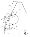
- Fig.1 illustrates a gas turbine engine 10 of a type preferably provided for use in subsonic flight, generally comprising in serial flow communication a fan 12 through which ambient air is propelled, a multistage compressor 14 for pressurizing the air, a combustor 16 in which the compressed air is mixed with fuel and ignited for generating an annular stream of hot combustion gases, and a turbine section 18 for extracting energy from the combustion gases.
- the hot combustion gases are exhausted through a nozzle/mixer 19 to produce thrust.
- the nozzle 19 includes an exhaust centerbody 20 centered therewithin by a plurality of hollow struts 11 to form an annular exhaust port defined within the surrounding enclosure 13.
- the enclosure also surrounds the turbine section 18 and defines an annular cavity 15 therein.
- a bypass air passage 17 is defined between the exhaust duct casing 13 and an engine outer casing 21.
- the exhaust centerbody has a central longitudinal axis 9 about which it is substantially symmetric, the axis 9 being coincident with a central longitudinally extending engine centerline C.
- the exhaust centerbody 20 comprises a first or forward portion 22 and a second or tailcone portion 24 which are serially connected together to form the somewhat frusto-conical shape of the exhaust centerbody 20.
- the forward portion 22 is hollow and comprises an annular outer wall 30 over and about which exhaust gas flows within the annular exhaust duct passage 31, the exhaust duct passage 31 being defined radially between the outer wall 30 of the centerbody 20 and the surrounding exhaust duct casing 13.
- the forward portion 22 includes a downstream end 32 having an annular flange 34, as will be described in further detail below.
- the tailcone portion 24 of the centerbody 20 is engaged to the downstream end 32 of the forward portion, so that the outer walls 30,38 form a continuous profile of the centerbody 20 within which a centerbody cavity 26 is defined.
- the tailcone portion 24 is also hollow and comprises an outer surface 38, a closed downstream end 40 and an open annular upstream end 42.
- the upstream end 42 is connected to the continuous rim 44 defined by the annular flange 34.
- the centerbody cavity 26 extends within the outer walls 30,38 of the centerbody 20 between the turbine section 18 (see Fig. 1 ) at the upstream end thereof and the closed downstream end 40.
- the cavity 26 usually contains the rearmost bearing housing of the engine as well as the oil supply for these bearings (not shown). These components require ventilation in order to prevent damage that could be caused by excess heat, as well as to reduce a risk of fire.
- the forward portion 22 of the centerbody 20 is supported and retained in place within the surrounding exhaust duct casing 13 by the plurality of support struts 11 radially extending between the outer wall 30 of the centerbody's forward portion 22 and the exhaust duct casing 13.
- the struts 11 are hollow and define an air flow passage therethrough, such that fluid flow communication between the centerbody cavity 26 and a source of cooling and/or ventilation air is provided.
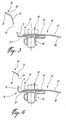
- This ventilation airflow may be either bypass duct air or compressed air from the engine, for example. Accordingly, as shown by the air-flow arrows in Fig. 2 , ventilation air is permitted to flow through the hollow struts 11 and into the cavity 26 within the centerbody 20, such as to provide a ventilation and cooling airflow to the centerbody cavity 26.
- This ventilation air therefore flows from the source of the cooling/ventilation air through the hollow struts 11 and into the cavity 26, before being ejected out into the main exhaust gas flow stream via a plurality of ventilation openings 50, as described further below.
- the forward centerbody portion 22 converges towards its own downstream end 32 that includes the annular flange 34, which itself comprises a first wall portion 35 and a second wall portion 37 downstream thereof.
- the second wall portion is, in at least the depicted embodiment, substantially parallel to the central longitudinal axis 9 of the centerbody (see Fig. 2 ), and therefore also to the central longitudinal engine centerline axis C (see Fig. 1 ).
- the first wall portion 35 is therefore disposed between the second wall portion 37 and the outer wall 30 of the centerbody's upstream portion 22.
- the first wall portion 35 is also inclined relative to each of these, being disposed at an angle relative to the second wall portion 37 (and therefore also at an angle relative to the central axis 9 of the centerbody 20).
- the first wall portion 35 is oriented at an obtuse angle relative to the second wall portion 37, i.e. the external angle ⁇ therebetween is between about 90 degrees and about 180 degrees.
- the first wall portion 35 is oriented approximately perpendicularly (i.e. about 90 degrees) to the second wall portion 37. Therefore, the external angle between the first wall portion 35 and the second wall portion 37 is at least 90 degrees (i.e. greater than or equal to approximately 90 degrees).
- the second wall portion 37 of the annular flange 34 is matingly engaged to the upstream end 42, and more particularly to the continuous and axisymmetric rim 44 thereof, of the tailcone portion 24.
- the second wall portion 37 is similarly axisymmetric and concentric with the rim 44, such that they can be mated together.
- the rim 44 of the tailcone 24 is preferably substantially parallel to the central axis 9 of the centerbody, and as such is also parallel to the second wall portion 37 about the entire circumference thereof.
- the rim 44 has an internal diameter that is slightly larger than an outer diameter of the second wall portion 37 of the annular flange 34, and as such the rim 44 overlaps at least a portion of the second wall portion 37 such that they can be fastened together.
- An alternate arrangement i.e.
- the second wall portion 37 of the upstream portion 22 and the rim 44 of the tailcone portion 24 are fastened together by a plurality of fasteners 48.
- These fasteners 48 may be removable, such as the bolts depicted for example, or alternately may be permanently fastened once engaged in place, such as rivets, for example.
- the bolts 48 as shown pass through correspondingly sized and aligned fastening holes in both the second wall portion 37 and the rim 44, and are fastened in place using either individual lock nuts 49 or a ring having a plurality of the corresponding threaded holes therein.
- Other means for fastening the two annular portions together may also be used, such as by welding, brazing, bonding, and the like.
- the fasteners 48 are preferably evenly spaced about the entire circumference of the annular flange 34.
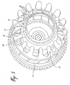
- the angled first wall portion 35 of the annular flange 34 defines therein a plurality of individual openings or holes 50 therein; about the entire circumference thereof.
- the openings 50 which are disposed in the step change defined by the annular flange 34 of the forward centerbody portion 32, act as ventilation openings, and provide fluid flow communication between the centerbody cavity 26 and the exhaust gas flow surrounding the centerbody 20.
- the plurality of ventilation openings 50 permit the centerbody cavity 26 to be ventilated such that cooling/ventilation air within the cavity 26 is free to exhaust out of the centerbody and into the exhaust gas flow.
- the first wall portion 35 is angled relative to the upstream and downstream outer walls 32 and 38, no overlap between these main outer walls 32, 38 exits at the joint between the forward centerbody portion 32 and the tailcone portion 24.
- the openings 50 are all located within the first wall portion 35, the lack of overlap covering the exit of the openings enable reduced obstructions to air flowing out of the openings.
- the first wall portion 35 having the openings 50 therein is located downstream relative to an end of the lobes of the exhaust mixer 19.
- the plurality of openings 50 are, in at least one embodiment, each substantially circular (i.e. are said to be "bullet holes") and have diameter sufficient to extend over a majority of the length of the first wall portion 35.
- the ventilation air which exits the openings 50 is intended to have negligible aerodynamically negative effects on the exhaust gas flow and therefore on the overall engine performance.
- the number of openings 50 will vary depending on the overall diameter of the annular flange 34, however a sufficient number of openings 50 are provided in the first wall portion 35 such that the total surface area of the openings 50 (i.e. the voids) is greater than the remaining surface area of the first wall portion 35.
- the plurality of openings 50 therefore provide good ventilation of the inner cavity 26 of the exhaust centerbody 20, and the structure and configuration of the annular flange 34, and more specifically the first wall portion 34 thereof in which the openings 50 are located, allows for the exhaust gas flowing over the outer surfaces of the wall of the centerbody to be substantially unaffected by the introduction therein of the exhausted ventilation cooling air from within the cavity 26.
- the centerbody 20 comprises two parts, that is the upstream portion 22 and the tailcone portion 24 which are mated together between the closed end 40 of the tailcone and the open upstream end of the upstream portion 22 at the annular flange 34 therebetween
- the centerbody 20 in another embodiment the centerbody 20 in fact formed of a single piece, wherein the upstream portion 22 and the tailcone portion 24 are integrally formed with each other.
- the outer wall 30 and 38 of the two portions form the substantially uninterrupted annular centerbody wall that extends between the complete upstream and downstream ends.
- the outer walls 30 and 38 of the upstream portion 22 and the tailcone portion 24 similarly form a substantially continuous profile of the centerbody 20, which is only interrupted by the annular flange 34.
- the annular flange 34 as described above with the plurality of ventilation openings 50 therein, is still disposed within the annular centerbody wall at a point between the upstream end and the closed downstream end thereof.
- the junction therebetween at the annular flange region 34 is such that the forward portion and the tailcone portion are fastened together at the annular flange without axial overlap, i.e. such that at least the first wall portion 35 is radially uncovered such air flowing through the ventilation openings 50 therein is ejected directly into the exhaust gas flow, without being obstructed or deflected by any object (such as a flap, deflector, protruding portion of the forward centerbody portion, etc.).
- This permits a smoother transition of the ventilation air as it flows into the main exhaust gas flow about the centerbody.
Landscapes
- Engineering & Computer Science (AREA)
- Chemical & Material Sciences (AREA)
- Combustion & Propulsion (AREA)
- Mechanical Engineering (AREA)
- General Engineering & Computer Science (AREA)
- Supercharger (AREA)
- Exhaust Silencers (AREA)
Claims (16)
- Noyau central pour le système d'échappement d'un moteur à turbine à gaz, le noyau central ayant un axe longitudinal central coïncidant avec celui du moteur à turbine à gaz, le noyau central comprenant :une extrémité amont montée au sein d'une enveloppe de tuyère d'éjection du système d'échappement, une extrémité aval fermée, et une paroi de noyau central annulaire (30) s'étendant entre les extrémités amont et aval, une cavité (28) définie au sein du noyau central et en communication avec une source de circulation d'air de ventilation ; etune pluralité d'ouvertures de ventilation (50) définie dans ladite paroi de noyau central, lesdites ouvertures de ventilation formant une communication de circulation de fluide entre la cavité (28) et une circulation de gaz d'échappement du moteur à turbine à gaz, de telle sorte que l'air de ventilation provenant de l'intérieur de la cavité peut sortir dans la circulation de gaz d'échappement ;caractérisé en ce que :les ouvertures de ventilation (50) de la pluralité sont circonférentiellement disposées autour de la paroi de noyau central (30. 38) au sein d'une paroi de flasque annulaire (35) de celle-ci, ladite paroi de flasque annulaire étant située entre ladite extrémité amont et ladite extrémité aval fermée et disposée à un angle de 90° ou à un angle obtus par rapport à l'axe longitudinal central (9) du noyau central.
- Noyau central selon la revendication 1, comprenant en outre des première (22) et seconde (24) portions raccordées ensemble en série.
- Noyau central selon la revendication 2, dans lequel la première portion (22) définit ladite extrémité amont et ladite seconde portion (44) définit ladite extrémité aval fermée, lesdites première et seconde portions étant accouplées ensemble à proximité de ladite paroi de flasque annulaire (34).
- Noyau central selon la revendication 3, dans lequel la première portion (22) définit ladite paroi annulaire de flasque (35) à une extrémité aval (32) de celle-ci, une seconde portion de paroi (37) étant disposée immédiatement en aval de la paroi de flasque annulaire (35), la seconde portion de paroi étant sensiblement parallèle à l'axe longitudinal central (9) du noyau central et la paroi de flasque annulaire (35) étant disposée entre la paroi de noyau central (30) et la seconde portion de paroi (37) audit angle de 90° ou angle obtus.
- Noyau central selon la revendication 4, dans lequel les première (22) et seconde (44) portions sont accouplées ensemble à proximité de la paroi de flasque annulaire (35) par une pluralité d'attaches (48) disposées autour de la circonférence de la seconde portion de paroi (37).
- Noyau central selon la revendication 4 ou 5, dans lequel la seconde portion (44) comporte une extrémité amont ouverte (42) qui est accouplée à la seconde portion de paroi (37) autour de sa circonférence.
- Noyau central selon la revendication 6, dans lequel l'extrémité amont ouverte (42) de la seconde portion (44) est une périphérie axisymétrique continue.
- Noyau central selon la revendication 7, dans lequel la périphérie s'étend dans une direction généralement parallèle à l'axe longitudinal central (9) et à la seconde portion de paroi (37).
- Noyau central selon la revendication 1, comprenant :une portion avant (22) définissant ladite extrémité amont et ayant une première surface externe (30) au-dessus de laquelle circule le gaz d'échappement, ladite paroi de flasque annulaire (35) étant à une extrémité aval (32) de la portion avant ; etune portion de cône de queue (24) définissant ladite extrémité aval fermée et ayant une seconde surface externe (38), la portion de cône de queue ayant une extrémité aval fermée (40) et une extrémité amont ouverte (42) ;la portion avant (22) comprenant en outre une seconde portion de paroi (37) en aval de la paroi de flasque annulaire (35), la seconde portion de paroi étant sensiblement parallèle à l'axe central (9) du noyau central et la paroi de flasque annulaire (35) étant disposée entre la première surface externe (30) et la seconde portion de paroi (37) à un angle d'au moins 90°C, de préférence à un angle obtus, par rapport à ladite seconde portion de paroi ;où l'extrémité amont ouverte de la portion de cône de queue (24) est accouplée à la seconde portion de paroi (37) de la portion avant (22) autour de la circonférence de la seconde portion de paroi (37) ; etoù la cavité (28) du noyau central est définie par les première et seconde surfaces externes (30, 38) et par l'extrémité aval fermée (40) de la portion de cône de queue (24).
- Noyau central selon la revendication 9, dans lequel l'extrémité ouverte (42) de la portion de cône de queue (24) est une périphérie axisymétrique continue.
- Noyau central selon la revendication 10, dans lequel la périphérie s'étend dans une direction généralement parallèle à l'axe central (9) et à la seconde portion de paroi (37) de la portion avant (22).
- Noyau central selon l'une quelconque des revendications 9 à 11, dans lequel l'extrémité ouverte (42) de la portion de cône de queue (24) est accouplée à la seconde portion de paroi (37) de la portion avant (22) par une pluralité d'attaches (48) disposées autour de la circonférence de la seconde portion de paroi (37).
- Noyau central selon l'une quelconque des revendications précédentes, dans lequel chacune de ladite pluralité d'ouvertures de ventilation (50) est sensiblement circulaire.
- Noyau central selon l'une quelconque des revendications précédentes, dans lequel les ouvertures de ventilation (50) de ladite pluralité sont distribuées de manière circonférentiellement uniforme autour de ladite paroi de flasque annulaire (35).
- Buse d'éjection d'un moteur à turbine à gaz comprenant un noyau central d'échappement tel que défini dans l'une quelconque des revendications précédentes, le noyau central d'échappement étant disposé dans une enveloppe de tuyère d'éjection, une circulation de gaz d'échappement passant par un passage de tuyère d'éjection annulaire entre le noyau central d'échappement et l'enveloppe de tuyère d'éjection alentour, et où le noyau central d'échappement est supporté au sein de l'enveloppe de tuyère d'éjection par une série de goujons (11) s'étendant radialement à travers ledit passage de tuyère d'éjection entre ladite extrémité amont du noyau central d'échappement et la tuyère d'éjection.
- Buse d'éjection selon la revendication 15, dans laquelle lesdits goujons (11) sont creux et définissent chacun un passage de circulation d'air au travers, lesdits passages de circulation d'air formant une communication de circulation de fluide entre la cavité de noyau central (28) et une source de circulation d'air de ventilation.
Applications Claiming Priority (1)
| Application Number | Priority Date | Filing Date | Title |
|---|---|---|---|
| US11/465,670 US7805925B2 (en) | 2006-08-18 | 2006-08-18 | Gas turbine engine exhaust duct ventilation |
Publications (3)
| Publication Number | Publication Date |
|---|---|
| EP1892405A2 EP1892405A2 (fr) | 2008-02-27 |
| EP1892405A3 EP1892405A3 (fr) | 2009-12-02 |
| EP1892405B1 true EP1892405B1 (fr) | 2011-08-03 |
Family
ID=38704723
Family Applications (1)
| Application Number | Title | Priority Date | Filing Date |
|---|---|---|---|
| EP07253253A Active EP1892405B1 (fr) | 2006-08-18 | 2007-08-17 | Ventilation de conduit d'échappement de moteur à turbine à gaz |
Country Status (4)
| Country | Link |
|---|---|
| US (1) | US7805925B2 (fr) |
| EP (1) | EP1892405B1 (fr) |
| CA (1) | CA2660211C (fr) |
| WO (1) | WO2008019493A1 (fr) |
Families Citing this family (28)
| Publication number | Priority date | Publication date | Assignee | Title |
|---|---|---|---|---|
| DE102007004741A1 (de) * | 2007-01-31 | 2008-08-07 | Mtu Aero Engines Gmbh | Gasturbine mit einem Nachleitkranz und mit einem Mischer |
| US9938900B2 (en) | 2011-05-26 | 2018-04-10 | United Technologies Corporation | Ceramic matrix composite turbine exhaust case for a gas turbine engine |
| US20120321451A1 (en) * | 2011-06-20 | 2012-12-20 | Hamilton Sundstrand Corporation | Bearing Housing Cooling System |
| FR2978988B1 (fr) * | 2011-08-12 | 2013-07-26 | Aircelle Sa | Cone d'ejection pour turboreacteur d'aeronef |
| US8641362B1 (en) * | 2011-09-13 | 2014-02-04 | Florida Turbine Technologies, Inc. | Turbine exhaust cylinder and strut cooling |
| US9511873B2 (en) * | 2012-03-09 | 2016-12-06 | The Boeing Company | Noise-reducing engine nozzle system |
| US20170082063A1 (en) * | 2012-03-09 | 2017-03-23 | The Boeing Company | Engine nozzle system for shock-cell noise reduction |
| US8985942B2 (en) | 2012-07-02 | 2015-03-24 | United Technologies Corporation | Turbine exhaust case duct |
| FR2994460B1 (fr) * | 2012-08-09 | 2018-04-27 | Safran Aircraft Engines | Cone d'ejection pour turbomachine comportant des moyens d'aspiration de couche limite d'un flux d'air |
| US9097134B2 (en) * | 2012-09-14 | 2015-08-04 | Pratt & Whitney Canada Corp. | Air cooling design for tail-cone generator installation |
| US20150377073A1 (en) * | 2013-03-15 | 2015-12-31 | United Technologies Corporation | Titanium aluminide turbine exhaust structure |
| US9759159B2 (en) | 2014-05-26 | 2017-09-12 | Pratt & Whitney Canada Corp. | Integrated turbine exhaust struts and mixer of turbofan engine |
| US20150075169A1 (en) * | 2013-09-19 | 2015-03-19 | Pratt & Whitney Canada Corp. | Integrated turbine exhaust struts and mixer of turbofan engine |
| US9850877B2 (en) | 2013-09-23 | 2017-12-26 | George F McBride | Spent flow discharge apparatus for an instream fluid power-extraction machine |
| FR3011035B1 (fr) * | 2013-09-25 | 2015-10-09 | Snecma | Carter d'echappement comprenant un dispositif d'evacuation de fluide, et turbomachine |
| CN104696074A (zh) * | 2013-12-10 | 2015-06-10 | 贵州黎阳航空动力有限公司 | 一种降低燃气轮机壁面及机撬内温度的结构 |
| US10018150B2 (en) | 2014-05-26 | 2018-07-10 | Pratt & Whitney Canada Inc. | Integrated TEC/mixer strut axial position |
| EP2982854B1 (fr) | 2014-08-08 | 2023-03-01 | Raytheon Technologies Corporation | Buse de sortie divergente convergente pour un moteur à turbine à gaz |
| FR3026786B1 (fr) * | 2014-10-07 | 2019-07-26 | Safran Aircraft Engines | Flasque de fermeture d'un carter d'echappement |
| US11105265B2 (en) * | 2016-09-02 | 2021-08-31 | Raytheon Technologies Corporation | Supplemental cooling air for turbine exhaust components and surfaces |
| US11118481B2 (en) * | 2017-02-06 | 2021-09-14 | Raytheon Technologies Corporation | Ceramic matrix composite turbine exhaust assembly for a gas turbine engine |
| US10927792B2 (en) * | 2018-06-22 | 2021-02-23 | The Boeing Company | Jet noise suppressor |
| FR3088968B1 (fr) * | 2018-11-27 | 2021-12-03 | Safran Aircraft Engines | Agencement de turboréacteur double flux à réducteur épicycloïdal ou planétaire |
| US11391179B2 (en) | 2019-02-12 | 2022-07-19 | Pratt & Whitney Canada Corp. | Gas turbine engine with bearing support structure |
| US11346249B2 (en) | 2019-03-05 | 2022-05-31 | Pratt & Whitney Canada Corp. | Gas turbine engine with feed pipe for bearing housing |
| FR3095675B1 (fr) * | 2019-05-03 | 2021-04-09 | Safran Aircraft Engines | Mélangeur à flux séparés de turbomachine |
| US11641144B2 (en) | 2021-02-08 | 2023-05-02 | General Electric Company | Gas turbine engines including embedded electrical machines and associated cooling systems |
| US11655732B2 (en) | 2021-05-14 | 2023-05-23 | Pratt & Whitney Canada Corp. | Turbine exhaust case mixer |
Family Cites Families (30)
| Publication number | Priority date | Publication date | Assignee | Title |
|---|---|---|---|---|
| US2934891A (en) * | 1956-08-31 | 1960-05-03 | United Aircraft Corp | Anti-screech inner body |
| US4044555A (en) * | 1958-09-30 | 1977-08-30 | Hayes International Corporation | Rear section of jet power plant installations |
| GB996461A (en) * | 1962-09-03 | 1965-06-30 | Bristol Siddeley Engines Ltd | Improvements relating to jet propulsion power plants |
| US3390837A (en) | 1965-12-08 | 1968-07-02 | Gen Electric | Convergent-divergent plug nozzle having a plurality of freely-floating tandem flaps |
| US3970252A (en) * | 1967-09-28 | 1976-07-20 | General Motors Corporation | Cooled exhaust duct |
| US3938742A (en) | 1973-02-13 | 1976-02-17 | The United States Of America As Represented By The United States National Aeronautics And Space Administration Office Of General Counsel-Code Gp | Cascade plug nozzle |
| FR2241695B1 (fr) | 1973-08-21 | 1978-03-17 | Bertin & Cie | |
| US3981143A (en) * | 1974-08-15 | 1976-09-21 | The United States Of America As Represented By The Secretary Of The Army | Infrared suppressor |
| US4085585A (en) * | 1976-06-28 | 1978-04-25 | Sharpe Thomas H | Impaction/induction jet engine |
| US4109864A (en) * | 1976-12-23 | 1978-08-29 | General Electric Company | Coolant flow metering device |
| US4196856A (en) * | 1977-11-25 | 1980-04-08 | The Boeing Company | Variable geometry convergent divergent exhaust nozzle |
| US4214441A (en) | 1978-09-12 | 1980-07-29 | The United States Of America As Represented By The Secretary Of The Navy | Infrared suppressor device |
| US4226297A (en) | 1979-01-12 | 1980-10-07 | United Technologies Corporation | Acoustic treated exhaust plug for turbine engine |
| US4240519A (en) * | 1979-07-02 | 1980-12-23 | United Technologies Corporation | Acoustical turbine engine tail pipe plug |
| CA1134627A (fr) * | 1979-08-09 | 1982-11-02 | Clayton G. Coffey | Systeme de repression des emissions dans l'infrarouge |
| US6253540B1 (en) | 1982-07-08 | 2001-07-03 | General Electric Company | Removable baffle infrared suppressor |
| US4720901A (en) * | 1982-08-23 | 1988-01-26 | The Boeing Company | Method of positioning an aircraft jet engine noise suppressor in a convergent jet engine nozzle |
| GB2149456B (en) | 1983-11-08 | 1987-07-29 | Rolls Royce | Exhaust mixing in turbofan aeroengines |
| US5941065A (en) | 1996-11-04 | 1999-08-24 | The Boeing Company | Stowable mixer ejection nozzle |
| US6012281A (en) * | 1997-08-18 | 2000-01-11 | United Technologies Corporation | Noise suppressing fluid mixing system for a turbine engine |
| US6178740B1 (en) | 1999-02-25 | 2001-01-30 | The Boeing Company | Turbo fan engine nacelle exhaust system with concave primary nozzle plug |
| US6584766B1 (en) * | 2000-03-24 | 2003-07-01 | General Electric Co. | Methods and apparatus for minimizing thermal stresses in a centerbody |
| US6502383B1 (en) | 2000-08-31 | 2003-01-07 | General Electric Company | Stub airfoil exhaust nozzle |
| US6505706B2 (en) | 2001-06-14 | 2003-01-14 | Pratt & Whitney Canada Corp. | Exhaust flow guide for jet noise reduction |
| CA2472604A1 (fr) * | 2002-01-09 | 2003-07-24 | The Nordam Group, Inc. | Tuyere a noyau central a surface variable |
| US7043898B2 (en) * | 2003-06-23 | 2006-05-16 | Pratt & Whitney Canada Corp. | Combined exhaust duct and mixer for a gas turbine engine |
| US7216475B2 (en) * | 2003-11-21 | 2007-05-15 | General Electric Company | Aft FLADE engine |
| US7032387B2 (en) * | 2004-01-20 | 2006-04-25 | Pratt & Whitney Canada Corp. | Axisymmetric flap on gas turbine exhaust centerbody |
| US7703270B2 (en) * | 2005-07-15 | 2010-04-27 | Pratt & Whitney Canada Corp. | Cable connection for a gas turbine engine safety fuel shut-off mechanism |
| US7614210B2 (en) * | 2006-02-13 | 2009-11-10 | General Electric Company | Double bypass turbofan |
-
2006
- 2006-08-18 US US11/465,670 patent/US7805925B2/en active Active
-
2007
- 2007-08-14 CA CA2660211A patent/CA2660211C/fr active Active
- 2007-08-14 WO PCT/CA2007/001420 patent/WO2008019493A1/fr active Application Filing
- 2007-08-17 EP EP07253253A patent/EP1892405B1/fr active Active
Also Published As
| Publication number | Publication date |
|---|---|
| US20080041033A1 (en) | 2008-02-21 |
| EP1892405A2 (fr) | 2008-02-27 |
| CA2660211C (fr) | 2011-06-14 |
| EP1892405A3 (fr) | 2009-12-02 |
| WO2008019493A1 (fr) | 2008-02-21 |
| CA2660211A1 (fr) | 2008-02-21 |
| US7805925B2 (en) | 2010-10-05 |
Similar Documents
| Publication | Publication Date | Title |
|---|---|---|
| EP1892405B1 (fr) | Ventilation de conduit d'échappement de moteur à turbine à gaz | |
| EP1074792B1 (fr) | Agencement de chambre de combustion de turbine | |
| US10739002B2 (en) | Fluidic nozzle assembly for a turbine engine | |
| US10995954B2 (en) | Gas turbine engine with igniter stack or borescope mount having noncollinear cooling passages | |
| US7500364B2 (en) | System for coupling flow from a centrifugal compressor to an axial combustor for gas turbines | |
| US8784051B2 (en) | Strut for a gas turbine engine | |
| US10253632B2 (en) | Compressor rim thermal management | |
| US9982630B2 (en) | Turbofan bypass air cooled oil cooler fairings | |
| US6988674B2 (en) | Method and apparatus for suppressing infrared signatures | |
| US9097140B2 (en) | Cavity ventilation | |
| US6401447B1 (en) | Combustor apparatus for a gas turbine engine | |
| US6513330B1 (en) | Diffuser for a gas turbine engine | |
| US9810148B2 (en) | Self-cooled orifice structure | |
| CA2909468A1 (fr) | Composante de moteur pour turbine a gaz | |
| EP0732547A1 (fr) | Chambre de combustion annulaire | |
| JP2017089638A (ja) | ガスタービンエンジン用冷却燃焼器 | |
| EP3196422B1 (fr) | Cadre d'échappement | |
| US10544702B2 (en) | Method and apparatus for supplying cooling air to a turbine | |
| CN110494693B (zh) | 单腔捕获涡流燃烧器 | |
| EP2045527A2 (fr) | Ensembles de dôme à facettes pour chambres de combustion de turbines à gaz | |
| US20120312027A1 (en) | Flow discharge device | |
| US11221143B2 (en) | Combustor and method of operation for improved emissions and durability | |
| US11788492B2 (en) | Reheat assembly | |
| US20220364729A1 (en) | Combustor dilution with vortex generating turbulators |
Legal Events
| Date | Code | Title | Description |
|---|---|---|---|
| PUAI | Public reference made under article 153(3) epc to a published international application that has entered the european phase |
Free format text: ORIGINAL CODE: 0009012 |
|
| AK | Designated contracting states |
Kind code of ref document: A2 Designated state(s): AT BE BG CH CY CZ DE DK EE ES FI FR GB GR HU IE IS IT LI LT LU LV MC MT NL PL PT RO SE SI SK TR |
|
| AX | Request for extension of the european patent |
Extension state: AL BA HR MK YU |
|
| PUAL | Search report despatched |
Free format text: ORIGINAL CODE: 0009013 |
|
| AK | Designated contracting states |
Kind code of ref document: A3 Designated state(s): AT BE BG CH CY CZ DE DK EE ES FI FR GB GR HU IE IS IT LI LT LU LV MC MT NL PL PT RO SE SI SK TR |
|
| AX | Request for extension of the european patent |
Extension state: AL BA HR MK RS |
|
| 17P | Request for examination filed |
Effective date: 20100204 |
|
| 17Q | First examination report despatched |
Effective date: 20100310 |
|
| AKX | Designation fees paid |
Designated state(s): DE FR GB |
|
| RIC1 | Information provided on ipc code assigned before grant |
Ipc: F02K 1/04 20060101AFI20101129BHEP Ipc: F02K 1/38 20060101ALI20101129BHEP Ipc: F02K 1/78 20060101ALI20101129BHEP |
|
| GRAP | Despatch of communication of intention to grant a patent |
Free format text: ORIGINAL CODE: EPIDOSNIGR1 |
|
| GRAS | Grant fee paid |
Free format text: ORIGINAL CODE: EPIDOSNIGR3 |
|
| GRAA | (expected) grant |
Free format text: ORIGINAL CODE: 0009210 |
|
| AK | Designated contracting states |
Kind code of ref document: B1 Designated state(s): DE FR GB |
|
| REG | Reference to a national code |
Ref country code: GB Ref legal event code: FG4D |
|
| REG | Reference to a national code |
Ref country code: DE Ref legal event code: R096 Ref document number: 602007016245 Country of ref document: DE Effective date: 20110929 |
|
| PLBE | No opposition filed within time limit |
Free format text: ORIGINAL CODE: 0009261 |
|
| STAA | Information on the status of an ep patent application or granted ep patent |
Free format text: STATUS: NO OPPOSITION FILED WITHIN TIME LIMIT |
|
| 26N | No opposition filed |
Effective date: 20120504 |
|
| REG | Reference to a national code |
Ref country code: DE Ref legal event code: R097 Ref document number: 602007016245 Country of ref document: DE Effective date: 20120504 |
|
| REG | Reference to a national code |
Ref country code: FR Ref legal event code: PLFP Year of fee payment: 10 |
|
| REG | Reference to a national code |
Ref country code: DE Ref legal event code: R082 Ref document number: 602007016245 Country of ref document: DE Representative=s name: SCHMITT-NILSON SCHRAUD WAIBEL WOHLFROM PATENTA, DE |
|
| REG | Reference to a national code |
Ref country code: FR Ref legal event code: PLFP Year of fee payment: 11 |
|
| REG | Reference to a national code |
Ref country code: FR Ref legal event code: PLFP Year of fee payment: 12 |
|
| P01 | Opt-out of the competence of the unified patent court (upc) registered |
Effective date: 20230530 |
|
| PGFP | Annual fee paid to national office [announced via postgrant information from national office to epo] |
Ref country code: GB Payment date: 20230720 Year of fee payment: 17 |
|
| PGFP | Annual fee paid to national office [announced via postgrant information from national office to epo] |
Ref country code: FR Payment date: 20230720 Year of fee payment: 17 Ref country code: DE Payment date: 20230720 Year of fee payment: 17 |