EP1892326A2 - Kunststofflaugenbehälter für eine Waschmaschine mit Anbindung für Schwingungsdämpfer - Google Patents
Kunststofflaugenbehälter für eine Waschmaschine mit Anbindung für Schwingungsdämpfer Download PDFInfo
- Publication number
- EP1892326A2 EP1892326A2 EP07015567A EP07015567A EP1892326A2 EP 1892326 A2 EP1892326 A2 EP 1892326A2 EP 07015567 A EP07015567 A EP 07015567A EP 07015567 A EP07015567 A EP 07015567A EP 1892326 A2 EP1892326 A2 EP 1892326A2
- Authority
- EP
- European Patent Office
- Prior art keywords
- tabs
- container according
- plastic container
- plastic
- arc portion
- Prior art date
- Legal status (The legal status is an assumption and is not a legal conclusion. Google has not performed a legal analysis and makes no representation as to the accuracy of the status listed.)
- Granted
Links
Images



Classifications
-
- D—TEXTILES; PAPER
- D06—TREATMENT OF TEXTILES OR THE LIKE; LAUNDERING; FLEXIBLE MATERIALS NOT OTHERWISE PROVIDED FOR
- D06F—LAUNDERING, DRYING, IRONING, PRESSING OR FOLDING TEXTILE ARTICLES
- D06F37/00—Details specific to washing machines covered by groups D06F21/00 - D06F25/00
- D06F37/20—Mountings, e.g. resilient mountings, for the rotary receptacle, motor, tub or casing; Preventing or damping vibrations
- D06F37/22—Mountings, e.g. resilient mountings, for the rotary receptacle, motor, tub or casing; Preventing or damping vibrations in machines with a receptacle rotating or oscillating about a horizontal axis
-
- D—TEXTILES; PAPER
- D06—TREATMENT OF TEXTILES OR THE LIKE; LAUNDERING; FLEXIBLE MATERIALS NOT OTHERWISE PROVIDED FOR
- D06F—LAUNDERING, DRYING, IRONING, PRESSING OR FOLDING TEXTILE ARTICLES
- D06F37/00—Details specific to washing machines covered by groups D06F21/00 - D06F25/00
- D06F37/26—Casings; Tubs
- D06F37/261—Tubs made by a specially selected manufacturing process or characterised by their assembly from elements
- D06F37/262—Tubs made by a specially selected manufacturing process or characterised by their assembly from elements made of plastic material, e.g. by injection moulding
-
- D—TEXTILES; PAPER
- D06—TREATMENT OF TEXTILES OR THE LIKE; LAUNDERING; FLEXIBLE MATERIALS NOT OTHERWISE PROVIDED FOR
- D06F—LAUNDERING, DRYING, IRONING, PRESSING OR FOLDING TEXTILE ARTICLES
- D06F37/00—Details specific to washing machines covered by groups D06F21/00 - D06F25/00
- D06F37/26—Casings; Tubs
- D06F37/267—Tubs specially adapted for mounting thereto components or devices not provided for in preceding subgroups
- D06F37/268—Tubs specially adapted for mounting thereto components or devices not provided for in preceding subgroups for suspension devices
-
- F—MECHANICAL ENGINEERING; LIGHTING; HEATING; WEAPONS; BLASTING
- F16—ENGINEERING ELEMENTS AND UNITS; GENERAL MEASURES FOR PRODUCING AND MAINTAINING EFFECTIVE FUNCTIONING OF MACHINES OR INSTALLATIONS; THERMAL INSULATION IN GENERAL
- F16F—SPRINGS; SHOCK-ABSORBERS; MEANS FOR DAMPING VIBRATION
- F16F1/00—Springs
- F16F1/36—Springs made of rubber or other material having high internal friction, e.g. thermoplastic elastomers
- F16F1/38—Springs made of rubber or other material having high internal friction, e.g. thermoplastic elastomers with a sleeve of elastic material between a rigid outer sleeve and a rigid inner sleeve or pin, i.e. bushing-type
- F16F1/3842—Method of assembly, production or treatment; Mounting thereof
-
- F—MECHANICAL ENGINEERING; LIGHTING; HEATING; WEAPONS; BLASTING
- F16—ENGINEERING ELEMENTS AND UNITS; GENERAL MEASURES FOR PRODUCING AND MAINTAINING EFFECTIVE FUNCTIONING OF MACHINES OR INSTALLATIONS; THERMAL INSULATION IN GENERAL
- F16F—SPRINGS; SHOCK-ABSORBERS; MEANS FOR DAMPING VIBRATION
- F16F9/00—Springs, vibration-dampers, shock-absorbers, or similarly-constructed movement-dampers using a fluid or the equivalent as damping medium
- F16F9/32—Details
- F16F9/54—Arrangements for attachment
-
- F—MECHANICAL ENGINEERING; LIGHTING; HEATING; WEAPONS; BLASTING
- F16—ENGINEERING ELEMENTS AND UNITS; GENERAL MEASURES FOR PRODUCING AND MAINTAINING EFFECTIVE FUNCTIONING OF MACHINES OR INSTALLATIONS; THERMAL INSULATION IN GENERAL
- F16C—SHAFTS; FLEXIBLE SHAFTS; ELEMENTS OR CRANKSHAFT MECHANISMS; ROTARY BODIES OTHER THAN GEARING ELEMENTS; BEARINGS
- F16C11/00—Pivots; Pivotal connections
- F16C11/04—Pivotal connections
- F16C11/06—Ball-joints; Other joints having more than one degree of angular freedom, i.e. universal joints
- F16C11/08—Ball-joints; Other joints having more than one degree of angular freedom, i.e. universal joints with resilient bearings
- F16C11/083—Ball-joints; Other joints having more than one degree of angular freedom, i.e. universal joints with resilient bearings by means of parts of rubber or like materials
-
- F—MECHANICAL ENGINEERING; LIGHTING; HEATING; WEAPONS; BLASTING
- F16—ENGINEERING ELEMENTS AND UNITS; GENERAL MEASURES FOR PRODUCING AND MAINTAINING EFFECTIVE FUNCTIONING OF MACHINES OR INSTALLATIONS; THERMAL INSULATION IN GENERAL
- F16C—SHAFTS; FLEXIBLE SHAFTS; ELEMENTS OR CRANKSHAFT MECHANISMS; ROTARY BODIES OTHER THAN GEARING ELEMENTS; BEARINGS
- F16C2340/00—Apparatus for treating textiles
-
- F—MECHANICAL ENGINEERING; LIGHTING; HEATING; WEAPONS; BLASTING
- F16—ENGINEERING ELEMENTS AND UNITS; GENERAL MEASURES FOR PRODUCING AND MAINTAINING EFFECTIVE FUNCTIONING OF MACHINES OR INSTALLATIONS; THERMAL INSULATION IN GENERAL
- F16C—SHAFTS; FLEXIBLE SHAFTS; ELEMENTS OR CRANKSHAFT MECHANISMS; ROTARY BODIES OTHER THAN GEARING ELEMENTS; BEARINGS
- F16C2361/00—Apparatus or articles in engineering in general
- F16C2361/53—Spring-damper, e.g. gas springs
-
- Y—GENERAL TAGGING OF NEW TECHNOLOGICAL DEVELOPMENTS; GENERAL TAGGING OF CROSS-SECTIONAL TECHNOLOGIES SPANNING OVER SEVERAL SECTIONS OF THE IPC; TECHNICAL SUBJECTS COVERED BY FORMER USPC CROSS-REFERENCE ART COLLECTIONS [XRACs] AND DIGESTS
- Y10—TECHNICAL SUBJECTS COVERED BY FORMER USPC
- Y10T—TECHNICAL SUBJECTS COVERED BY FORMER US CLASSIFICATION
- Y10T74/00—Machine element or mechanism
- Y10T74/17—Rotary driven device adjustable during operation relative to its supporting structure
- Y10T74/173—Screw and nut adjusting means
Definitions
- the invention relates to a plastic tub for a washing machine, in the horizontal axis of a driven washing drum is rotatably mounted, and the plastic tub is arranged to vibrate in the machine housing, wherein for mounting at least one vibration damper on the plastic tub two tabs are provided through which are aligned holes, wherein between the tabs a fastening eye of the vibration damper is arranged, and for fixing the vibration damper, the holes and the fastening eye passing through fastener is arranged on the tabs.
- Vibration dampers on vibrating units of washing machines have the task in their direction of effect to dampen the movement in case of imbalance by washing and to prevent a striking or the offset of the device.
- torsional movements of the tub around the drum axis are initiated only by the associated displacement of the attachment point in the shock absorber.
- the attachment points of the damper on the tub and on the housing-side mounting can also transmit torques.
- the possibility of transmission is provided by a strongly screwed-on connection which generates a frictional connection via the prestressing force. This is not feasible in this form with plastic elements, since the required force would damage the plastic and its relaxation action has a rapid decrease in the bias result.
- the problem is to improve a plastic container with respect to the attachment of the vibration damper.
- the embodiment of the invention allows the transmission of torque in the attachment points of the shock absorbers to achieve the high imbalance absorption.
- the load of the plastic and ultimately the height of the transmittable torque can be adjusted accurately and reliably through the sleeve or through the collar of the screw or nut.
- the forces are intercepted or transmitted via frictional engagement with the insides of the lugs formed on the tub. This is done via the biasing force of the screw.
- the plastic is loaded only as far as he can bear without or little permanent deformation, and in addition a torque can be transmitted over the surface.
- the so-called cage solution It is particularly advantageous in the so-called cage solution that a part and assembly time reduction is achieved when inserting this connection, since no washers are required between the mounting eye of the vibration and the inner surfaces of the tabs.
- an S-shape exhibiting molded part is integrated with aligned holes in the vicinity of the adjacent plates for transmitting the shock absorber torque.
- the first arc portion is U-shaped and arranged between the tabs or between the inner plastic surfaces of the tabs, wherein the second arc portion is arranged across the free end of one of the tabs. Due to this shape results in a simple insertion and positioning of the molding.
- a holding device for the nut of a bolt passing through the holes of tabs and the molding screw shaft is arranged on the second arc portion, which projects beyond one of the aligned leg bores. This results in a security against rotation of the nut, if over the screw shaft, the bracing of the attachment.
- the holding device is designed for a square nut.
- the tabs form a bearing block, which has a substantially U-shape.
- the aligned bores of the first arc portion which fits into the U-shape of the bearing block between the tabs, have diameters corresponding to the inner diameter of the fastening eye.
- an elastically mounted joint bushing is present, being prevented that this bushing can press or eat into the plastic of the tabs.
- a solid contact surface is given, which can also be tightened accordingly with the bolt.
- the aligned bore of the second arc portion which extends across over one of the aligned holes of a tab end, a corresponding larger diameter as the tab holes. This is used to arrange on the nut side a flange in the holes of the molding and legs, which bridges the diameter difference in the screw shaft.
- the screw shaft as such is formed such that adjoins an area on the screw head, which corresponds to the diameter range of the tab hole, followed by the shaft, the diameter of the inner diameter of mounting eye or joint sleeve, the diameters of the holes of the first arc portion and the Flange sleeve corresponds.
- the screw shaft is attached with a groove on the larger diameter portion or provided at the transition region to the region with the larger diameter with a groove.
- the molded part is made of a one-piece bent metal part, so that on the one hand, the mother protection and the Verspannrial is achieved in the bearing block as a result of the insertion of the molding. It only needs then the screw shaft are performed, and then to clamp with the screw head, the entire fastening system.
- the molded part is resilient, so that it is held in its U-shaped region by clamping action against the inside of the tabs in its position. As a result, it can not be lost during assembly after insertion into the bearing block.
- the second arc portion of the molded part is resilient, so that it overlaps the free tab end on the outside with a clamping action. As a result, the predetermined position of the molded part in the bearing block is maintained during assembly in addition to the secure hold.
- the tabs on the inwardly facing sides each have a guide projection whereby the first arc portion of the S-shaped molding is positionable.
- the molding is reliably secured against rotation. The insertion of the molding is also facilitated by this guide.
- the free edges of the tabs on their inner sides each have an insertion bevel.
- the insertion of the shock absorber eye is facilitated in the first arc portion of the molding.
- outside guide webs mounted between which the holding device and / or nut can be inserted and positioned.
- the cage-like holding device is guided for the mother when inserting in the correct position, the webs prevent co-rotation of the nut when screwing.
- a recess is arranged at the free end of the tab for the second arc portion as coding in which the apex portion of the second arc portion is insertable.
- the indentation is arranged only on this one tab and designed so that the nut is aligned with the bore only when the apex portion is fully inserted in the recess. In this way it is avoided that the molding is mounted the wrong way round.
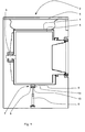
- FIG. 1 shows a schematic representation of a plastic tub 1 for a washing machine 2, in whose horizontal axis 3 a driven washing drum 4 is rotatably mounted.
- the plastic tub 1 is arranged to vibrate in the machine housing 5, wherein at least one vibration damper 6 is provided on a bearing block 7 on the plastic container 1.
- the bearing block 7 essentially comprises a U-shape, through the lugs 8 and 9 aligned bores 10 and 11 extend, the better in the detail view of Figure 2 can be seen are.
- the attachment eye 13 or an elastically mounted joint bush 12 inserted therein is arranged between the lugs 8 and 9.
- a vibration-damped pivot axis is formed within the fastening eye 13.
- a bores 10 and 11 and the joint bushing 12 penetrating fastening element 14 is arranged on the bearing block 7.
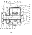
- Fig. 3 it is shown that for transmitting power or for transmitting a high shock absorber moment on the inner plastic surfaces of the tabs 8 and 9 in the region of the bearing block 7, in the bearing block 7 an S-shaped molded part 15 with aligned holes 16 and 17 integrated is, whose first arc portion 18, the U-shape of the bearing block 7, between the inner sides of the tabs 8 and 9 is arranged, wherein the second arc portion 19 of the free tab ends, here 8, extends across the outside.
- the molded part 15 is made of an integrally bent metal part, wherein the resilient property of the metal provides a clamping action of the first arc portion 18 between the tabs 8 and 9 and / or the second arc portion 19 outside the free end of a tab 8.
- a holding device designed as a cage 20 for a nut 21 is arranged on the second arc portion 19, which protrudes in particular via one of the aligned tab holes.
- the holding device 20 as it is in particular in the figure 4, formed for receiving a square nut 21.
- an elastically mounted joint bushing 12 is located in the fastening eye 13, an elastomeric ring 23 being pressed around the joint bushing 12 around which the fastening eye 13 of the shock absorber 6 is located. This results in a framed joint bushing 12, which transmits in particular a vibration-damped torque on the tabs 8 and 9.
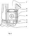
- Fig. 4 can be seen in a side view of the outside of the tab 8 that the second arc portion 19, the flap 8 at least partially covered on the outside.
- the cage-like holding device 20 is arranged or integrally formed.
- the square nut 21 is inserted in the threaded opening the free shank end 29 protrudes or is screwed in and fixes or stores over the attachment eye 13 (FIG. 3) of the shock absorber 6 located behind the lug 8.
- the free end of this tab 8 is further arranged as a coding means a recess 32, in which the region of the apex of the second arc portion 19 is inserted.
- the indentation 32 is arranged only at this one tab 8 and designed so that the nut 21 only with the bore 10 (Fig. 2) is aligned when the apex portion is completely in the recess 32. If the molding is mounted the wrong way around, then the apex area lies on the free end of the tab 9 without indentation. In this case, the nut 21 is not positioned flush with the bore 11 ( Figure 2) in the tab 9. A screw is not possible with this incorrect positioning of the molding 15.
- the aligned bores 16 and 17 of the first arc region 18 are in the U-shape of the bearing block 7 between the legs 8 and 9 Fits, each diameter D1, which correspond to the inner diameter D2 of the joint bush 12.
- This can be clearly seen in FIG. 3, wherein there is essentially a flush between the inner diameter D 2 and the diameter D 1.
- the aligned bore 24 of the second arc portion 19, which extends across one of the aligned holes, here 10, the tab 8, has a corresponding larger diameter D3 as the tab holes D4. It can be seen in FIG.
- a flange sleeve 25 is arranged in the bore 24 and in the bore 10 of the tab, here 8, which bridges the diameter difference between D1, D2 and D3, D4 to the screw shank 22.
- the screw head 26 of the screw shank 22 has an enlarged abutment surface 27, which effects the sufficient screwing or bracing force against the outer surface of the tab 9.
- adjoining the screw head 26 is a region 28, which corresponds to the diameter region D4 of the tab bore, which is adjoined by shank 22, whose diameter coincides with the inner diameter D2 of the joint bush 12, the diameters D1 of the bores 16 and 17 of the first arc region 18 , as well as the flange sleeve 25 corresponds.
- the screw shank 22 is provided with a groove 30 at the transition region to the region 28 of the screw head 26, wherein the shank 22 has a larger diameter D 2 in its further extent towards the end.
- the molded part 15 is inserted in the bearing block 7. Then, the flange sleeve 25 is attached to the tab 8, before then the fastening eye 13 is inserted with its elastically mounted joint bushing 12 between the tabs 8, 9 so that the screw shaft 22 can be set by the aligned holes 10 and 11. If this is done, only a nut 21 is still inserted into the cage-shaped holding device 20, which 26 automatically attracts when tightening the screw head.
- the holding device 20 is designed so that the nut 21 can be inserted into it in advance in a pre-locking position and is positioned together with the shaped part 15 in or on the bearing block 7. The tension of the parts ensures a vibration-damped torque.
- This molded part 15 thus has the particular advantage that high clamping forces can be transmitted to a bearing block 7 made of plastic or to the tabs 8 and 9.
- FIG. 5 once again shows, in an isolated sectional view, the fastening eye 13 of the vibration damper 6, in which the elastic ring 23 lies, in which the joint bushing 12 is integrated, which is penetrated by the screw shaft 22.
- Behind the fastening eye 13 is a part of the first one Bougereichs 18 of the molded part 15 (Fig. 3) can be seen, which provides the lateral abutment of the fastening eye 13 and the hinge bushing 12 on the tab 8.
- Fig. 6 the bearing block 7 is shown as a sectional view from above. All directions refer to the operational position of the washing machine.
- guide projections 30 are arranged on the free edge on the inner surfaces. Behind the guide projections is the first arcuate portion 18 of the molding 15 ( Figure 3).
- 8 and 9 insertion bevels 33 are arranged at the free ends of the tabs, which facilitate the insertion of the fastening eye 13 or the joint bush 12.
- a rotation of the first arc portion 18 around the axis acting screw shaft 22 is prevented.
Landscapes
- Engineering & Computer Science (AREA)
- General Engineering & Computer Science (AREA)
- Textile Engineering (AREA)
- Mechanical Engineering (AREA)
- Manufacturing & Machinery (AREA)
- Main Body Construction Of Washing Machines And Laundry Dryers (AREA)
- Vibration Prevention Devices (AREA)
- Fluid-Damping Devices (AREA)
- Springs (AREA)
- Bolts, Nuts, And Washers (AREA)
- Moulds For Moulding Plastics Or The Like (AREA)
Abstract
Description
- Die Erfindung betrifft einen Kunststofflaugenbehälter für eine Waschmaschine, in dessen horizontaler Achse eine angetriebene Waschtrommel drehbar gelagert ist, und der Kunststofflaugenbehälter schwingungsbeweglich in dem Maschinengehäuse angeordnet ist, wobei zur Befestigung wenigstens eines Schwingungsdämpfers an dem Kunststofflaugenbehälter zwei Laschen vorgesehen sind, durch welche fluchtende Bohrungen verlaufen, wobei zwischen den Laschen ein Befestigungsauge des Schwingungsdämpfers angeordnet ist, und zur Festlegung des Schwingungsdämpfers ein die Bohrungen und das Befestigungsauge durchsetzendes Befestigungselement an den Laschen angeordnet ist.
- Schwingungsdämpfer an schwingenden Aggregaten von Waschautomaten haben die Aufgabe in ihrer Wirkungsrichtung die Bewegung bei Unwucht durch Wäsche zu dämpfen und ein Anschlagen oder den Versatz des Gerätes zu verhindern. Torsionsbewegungen des Laugenbehälters um die Trommelachse werden jedoch nur durch die damit verbundene Verschiebung des Befestigungspunktes in die Stoßdämpfer eingeleitet. Die Befestigungspunkte des Dämpfers am Laugenbehälter und an der gehäuseseitigen Befestigung können auch Drehmomente übertragen. Bei Stahlaggregaten und Bodenwannen ist die Übertragungsmöglichkeit durch eine stark angeschraubte Verbindung gegeben, die über die Vorspannkraft eine kraftschlüssige Verbindung erzeugt. Das ist in dieser Form bei Kunststoffelementen nicht durchführbar, da die erforderliche Kraft den Kunststoff schädigen würde und seine Relaxaktion ein schnelles Absinken der Vorspannung zur Folge hat.
- Um insbesondere eine möglichst schwingungsgedämpfte Schwenkachse zu erhalten, wird im Stand der Technik, gemäß der
DE 197 25 706 A1 , eine Befestigungseinrichtung offenbart, bei der das Befestigungselement aus zwei quer zur Schwenkachse angeordneten aufspreizbaren Hülsensegmenten besteht. Auch wenn infolge der Aufspreizung des Befestigungselementes eine gewisse Versteifung der Schwenkachse gegeben ist, so ist diese bekannte Spreizhülse nicht verwendbar für Kunststofflaugenbehälter, und hier insbesondere für die an dem Kunststofflaugenbehälter angeformten Laschen. - Somit stellt sich für die Erfindung das Problem, einen Kunststofflaugenbehälter hinsichtlich der Befestigung des Schwingungsdämpfers zu verbessern.
- Erfindungsgemäß wird dieses Problem gelöst durch den Anspruch 1. Weiterbildungen ergeben sich aus den Unteransprüchen.
- Die erfindungsgemäße Ausführungsform ermöglicht die Drehmomentübertragung in den Befestigungspunkten der Stoßdämpfer zur Erzielung der hohen Unwuchtaufnahme. Die Belastung des Kunststoffes und letztendlich die Höhe des übertragbaren Drehmomentes lässt sich durch die Hülse bzw. durch den Bund der Schraube bzw. der Mutter genau und prozesssicher anpassen. Die Kräfte werden über Reibschluss an die Innenseiten der am Laugenbehälter angeformten Laschen abgefangen bzw. übertragen. Das geschieht über die Vorspannkraft der Schraube. Durch diese definierte Vorspannung wird der Kunststoff nur soweit belastet, wie er ohne bzw. geringe bleibende Verformung ertragen kann, und zusätzlich kann ein Drehmoment über die Fläche übertragen werden.
- Besonders vorteilhaft ist es bei der so genannten Käfiglösung, dass eine Teile- und Montagezeitreduzierung beim Einsetzen dieser Verbindung erzielt wird, da zwischen dem Befestigungsauge des Schwingungsdämpfers und den Innenflächen der Laschen keine Unterlegscheiben benötigt werden. Hierzu wird im Bereich der benachbarten Laschen zur Übertragung des Stoßdämpferdrehmomentes ein eine S-Form aufweisendes Formteil mit fluchtenden Bohrungen eingebunden. Dabei ist der erste Bogenbereich U-förmig ausgebildet und zwischen den Laschen bzw. zwischen innen liegenden Kunststoffflächen der Laschen angeordnet, wobei der zweite Bogenbereich über das freie Ende einer der Laschen übergreifend angeordnet ist. Aufgrund dieser Formgebung ergibt sich ein einfaches Einsetzen und Positionieren des Formteils.
- In Weiterbildung ist an dem zweiten Bogenbereich, der über eine der fluchtenden Schenkelbohrungen hinausragt, eine Haltevorrichtung für die Mutter eines die Bohrungen von Laschen sowie des Formteils durchsetzenden Schraubenschaftes angeordnet. Dadurch ergibt sich eine Verdrehsicherheit der Mutter, wenn über den Schraubenschaft die Verspannung der Befestigung erfolgt. Die Haltevorrichtung ist hierbei für eine Vierkantmutter ausgelegt.
- In einer zweckmäßigen Ausführung bilden die Laschen einen Lagerbock, der im Wesentlichen eine U-Form aufweist. Hierdurch wird eine besonders stabile und zuverlässige Befestigung des Schwingungsdämpfers bereitgestellt.
- Um insbesondere die Drehmomentkräfte im Bereich des Lagerbocks abzufangen, weisen die fluchtenden Bohrungen des ersten Bogenbereichs, der sich in die U-Form des Lagerbocks zwischen den Laschen einpasst, Durchmesser auf, die dem Innendurchmesser des Befestigungsauges entsprechen. Dies ist insbesondere von Vorteil, wenn im Befestigungsauge eine elastisch gelagerte Gelenkbuchse vorhanden ist, wobei verhindert wird, dass sich diese Buchse in den Kunststoff der Laschen eindrücken bzw. einfressen kann. Somit ist eine feste Anlagefläche gegeben, die auch entsprechend mit dem Schraubenbolzen verspannt werden kann.
- In einer vorteilhaften Ausführung weist die fluchtende Bohrung des zweiten Bogenbereichs, der sich übergreifend über eine der fluchtenden Bohrungen des einen Laschenendes erstreckt, einen entsprechenden größeren Durchmesser wie die Laschenbohrungen auf. Der wird dazu genutzt, um mutterseitig eine Flanschhülse in den Bohrungen von Formteil und Schenkel anzuordnen, die die Durchmesserdifferenz im Schraubenschaft überbrückt.
- Um die hinreichende Kraft auf den Lagerbock ausüben zu können, weist der Schraubenkopf des Schraubenschaftes eine vergrößerte Anlagefläche auf.
- Der Schraubenschaft als solches ist derart ausgebildet, dass sich am Schraubenkopf ein Bereich anschließt, der dem Durchmesserbereich der Laschenbohrung entspricht, an dem sich der Schaft anschließt, dessen Durchmesser dem Innendurchmesser von Befestigungsauge bzw. Gelenkhülse, den Durchmessern der Bohrungen des ersten Bogenbereichs sowie dem der Flanschhülse entspricht.
- In einer zweckmäßigen Weiterbildung ist der Schraubenschaft mit einer Hohlkehle an dem größeren Durchmesserbereich angesetzt bzw. am Übergangsbereich zum Bereich mit dem größeren Durchmesser mit einer Hohlkehle versehen.
- In einer besonders vorteilhaften Ausführung ist das Formteil aus einem einstückig gebogenen Metallteil hergestellt, so dass infolge des Einsetzens des Formteils einerseits die Muttersicherung als auch die Verspannwirkung im Lagerbock erreicht wird. Es braucht dann lediglich noch der Schraubenschaft durchgeführt werden, um dann mit dem Schraubenkopf das gesamte Befestigungssystem zu verspannen.
- In einer zweckmäßigen Weiterbildung ist das Formteil federnd ausgeführt, so dass es im U-förmigen Bereich durch Klemmwirkung gegen die Innenseite der Laschen in seiner Position gehalten wird. Hierdurch kann es bei der Montage nach dem Einsetzen in den Lagerbock nicht verloren gehen.
- In einer weiteren zweckmäßigen Weiterbildung ist der zweite Bogenbereich des Formteils federnd ausgeführt, so dass dieser das freie Laschenende auf dessen Außenseite mit einer Klemmwirkung übergreift. Hierdurch wird bei der Montage neben dem sicheren Halt auch die vorbestimmte Position des Formteils in dem Lagerbock beibehalten.
- In einer vorteilhaften Ausführung besitzen die Laschen auf den nach innen zugewandten Seiten jeweils einen Führungsvorsprung wodurch der erste Bogenbereich des S-förmigen Formteils positionierbar ist. Dadurch wird das Formteil zuverlässig gegen Verdrehen gesichert. Das Einführen des Formteils wird durch diese Führung ebenfalls erleichtert.
- In einer zweckmäßigen Weiterbildung besitzen die freien Ränder der Laschen auf ihren Innenseiten jeweils eine Einführschräge. Dadurch wird das Einsetzen des Stoßdämpferauges in den ersten Bogenbereich des Formteils erleichtert.
- In einer vorteilhaften Ausführung sind an der Lasche, die durch den zweiten Bogenbereich umgriffen wird, außenseitig Führungsstege angebracht, zwischen denen die Haltevorrichtung und / oder Mutter einführbar und positionierbar ist. Hierbei wird die käfigartige Haltevorrichtung für die Mutter beim Einsetzen in der richtigen Position geführt, wobei die Stege ein Mitdrehen der Mutter beim Verschrauben verhindern.
- In einer weiteren Ausführung ist am freien Ende der Lasche für den zweiten Bogenbereich als Kodiermittel eine Einbuchtung angeordnet, in die der Scheitelbereich des zweiten Bogenbereichs einführbar ist. Die Einbuchtung ist nur an dieser einen Lasche angeordnet und so ausgeführt, dass die Mutter erst dann mit der Bohrung fluchtet, wenn der Scheitelbereich vollständig in der Einbuchtung eingeführt ist. Auf diese Weise wird vermieden, dass das Formteil falsch herum montiert wird.
- Ein Ausführungsbeispiel der Erfindung wird anhand der nachstehenden Figuren 1 bis 5 näher erläutert; dabei zeigen:
- Figur 1:
- eine schematische Darstellung eines Waschmaschinengehäuses mit innen liegendem Waschaggregat, welches schwingungsgedämpft ist;
- Figur 2:
- eine Einzeldarstellung eines angeformten Lagerbocks an einem Kunststofflaugenbehälter;
- Figur 3:
- eine geschnittene Darstellung der Befestigung eines Befestigungsauges eines Stoßdämpfers zwischen den Laschen eines Lagerbocks in einer seitlichen Ansicht;
- Figur 4:
- eine weitere perspektivische Darstellung der Haltevorrichtung;
- Figur 5:
- eine weitere geschnittene Darstellung durch das Befestigungsauge eines Stoßdämpfers und
- Figur 6
- eine geschnittene Darstellung der Befestigung in der Draufsicht.
- Die Figur 1 zeigt in der Prinzipdarstellung einen Kunststofflaugenbehälter 1 für eine Waschmaschine 2, in dessen horizontaler Achse 3 eine angetriebene Waschtrommel 4 drehbar gelagert ist. Der Kunststofflaugenbehälter 1 ist dabei schwingungsbeweglich in dem Maschinengehäuse 5 angeordnet, wobei wenigstens ein Schwingungsdämpfer 6 an einem Lagerbock 7 am Kunststofflaugenbehälter 1 vorgesehen ist. Wie aus der Prinzipsskizze deutlich zu erkennen ist, umfasst hierbei der Lagerbock 7 im Wesentlichen eine U-Form, durch dessen Laschen 8 und 9 fluchtende Bohrungen 10 und 11 verlaufen, die besser in der Detailansicht der Figur 2 zu erkennen sind. Gemäß Fig. 3 ist zwischen den Laschen 8 und 9 das Befestigungsauge 13 bzw. eine darin eingesetzte elastisch gelagerte Gelenkbuchse 12 angeordnet. Durch die elastisch gelagerte Gelenkbuchse 12 wird innerhalb des Befestigungsauges 13 eine schwingungsgedämpfte Schwenkachse gebildet. Zur Festlegung des Schwingungsdämpfers 6 ist ein die Bohrungen 10 und 11 und die Gelenkbuchse 12 durchsetzendes Befestigungselement 14 am Lagerbock 7 angeordnet.
- In Fig. 3 ist dargestellt, dass zur Kraftübertragung bzw. zur Übertragung eines hohen Stoßdämpfermomentes auf die innen liegenden Kunststoffflächen der Laschen 8 und 9 im Bereich des Lagerbocks 7, in dem Lagerbock 7 ein S-förmiges Formteil 15 mit fluchtenden Bohrungen 16 und 17 eingebunden wird, dessen erster Bogenbereich 18, der U-Form des Lagerbocks 7 folgend, zwischen den Innenseiten der Laschen 8 und 9 angeordnet ist, wobei sich der zweite Bogenbereich 19 eines der freien Laschenenden, hier 8, außenseitig übergreifend erstreckt. Somit ergibt sich ein Formteil 15, welches sich formschlüssig einerseits zwischen den Laschen 8 und 9 einfügt, und andererseits gegen Verdrehung durch den übergreifenden zweiten Bogenbereich 19 gesichert ist, wobei auch gewährleistet wird, dass durch diese Formgebung auch eine Selbsthalterung des Formteils 15 im angeformten Lagerbock 7 erzielt wird, um auf diese Weise auch eine leichte Montage der zur Vervollständigung der Befestigung erforderlichen Teile zu ermöglichen. Dabei ist das Formteil 15 aus einem einstückig gebogenen Metallteil hergestellt, wobei die federnde Eigenschaft des Metalls eine Klemmwirkung des ersten Bogenbereichs 18 zwischen den Laschen 8 und 9 und/oder des zweiten Bogenbereichs 19 außenseitig um das freie Ende der einen Lasche 8 bereitstellt.
- Dabei ist an dem zweiten Bogenbereich 19, der insbesondere über eine der fluchtenden Laschenbohrungen hinausragt, eine als Käfig ausgebildete Haltevorrichtung 20 für eine Mutter 21 angeordnet. In diese Mutter 21 wird der die Bohrungen 10 und 11 von den Laschen 8 und 9 durchsetzende Schraubenschaft 22 eingeschraubt. Dabei ist die Haltevorrichtung 20, so wie sie sich insbesondere in der Figur 4 darstellt, zur Aufnahme einer Vierkantmutter 21 ausgebildet. Wie aus der Figur 3 nun ersichtlich ist, befindet sich in dem Befestigungsauge 13 eine elastisch gelagerte Gelenkbuchse 12, wobei hier um die Gelenkbuchse 12 ein elastomerer Ring 23 gedrückt ist, um den dann das Befestigungsauge 13 des Stoßdämpfers 6 liegt. Somit ergibt sich eine eingefasste Gelenkbuchse 12, die insbesondere ein Drehmoment schwingungsgedämpft auf die Laschen 8 und 9 überträgt.
- In Fig. 4 ist in einer seitlichen Ansicht auf die Außenseite der Lasche 8 zu erkennen, dass der zweite Bogenbereich 19 die Lasche 8 zumindest teilweise außenseitig überdeckt. An diesem zweiten Bogenbereich 19 ist die käfigartige Haltevorrichtung 20 angeordnet bzw. einstückig angeformt. In diese Haltevorrichtung ist die Vierkantmutter 21 eingelegt, in deren Gewindeöffnung das freie Schaftende 29 hindurchragt bzw. eingeschraubt ist und über das hinter der Lasche 8 befindliche Befestigungsauge 13 (Fig. 3) des Stoßdämpfers 6 befestigt bzw. lagert. Am freien Ende dieser Lasche 8 ist als Kodiermittel ferner eine Einbuchtung 32 angeordnet, in die der Bereich des Scheitels des zweiten Bogenbereichs 19 eingelegt ist. Die Einbuchtung 32 ist nur an dieser einen Lasche 8 angeordnet und so ausgeführt, dass die Mutter 21 erst dann mit der Bohrung 10 (Fig. 2) fluchtet, wenn sich der Scheitelbereich vollständig in der Einbuchtung 32 befindet. Wenn das Formteil falsch herum montiert wird, dann liegt der Scheitelbereich auf dem freien Ende der Lasche 9 ohne Einbuchtung auf. In diesem Fall ist die Mutter 21 nicht fluchtend mit der Bohrung 11 (Fig. 2) in der Lasche 9 positioniert. Eine Verschraubung ist bei dieser falschen Positionierung des Formteils 15 nicht möglich.
- Um insbesondere die Verspannkräfte gezielt auf die Gelenkbuchse 12 bzw. die Innenflächen der Kunststofflaschen 8 und 9 übertragen zu können, weisen die fluchtenden Bohrungen 16 und 17 des ersten Bogenbereichs 18, der sich in die U-Form des Lagerbocks 7 zwischen den Schenkeln 8 und 9 einpasst, jeweils Durchmesser D1 auf, die dem Innendurchmesser D2 der Gelenkbuchse 12 entsprechen. Dies ist deutlich in der Figur 3 zu erkennen, wobei im Wesentlichen eine Bündigkeit zwischen dem Innendurchmesser D2 und dem Durchmesser D1 gegeben ist. Die fluchtende Bohrung 24 des zweiten Bogenbereichs 19, der sich übergreifend über eine der fluchtenden Bohrungen, hier 10, der Lasche 8 erstreckt, weist einen entsprechenden größeren Durchmesser D3 wie die Laschenbohrungen D4 auf. Zu erkennen ist in der Figur 3, dass hierbei mutterseitig eine Flanschhülse 25 in der Bohrung 24 und in der Bohrung 10 der Lasche, hier 8, angeordnet ist, die die Durchmesserdifferenz zwischen D1, D2 und D3, D4 zum Schraubenschaft 22 überbrückt.
- Wie aus der Figur 3 zu erkennen ist, weist der Schraubenkopf 26 des Schraubenschaftes 22 eine vergrößerte Anlagefläche 27 auf, die die hinreichende Verschraubungs- bzw. Verspannkraft an die Außenfläche der Lasche 9 bewirkt. Dabei schließt sich an dem Schraubenkopf 26 ein Bereich 28 an, der dem Durchmesserbereich D4 der Laschenbohrung entspricht, an dem sich Schaft 22 anschließt, dessen Durchmesser mit dem Innendurchmesser D2 von der Gelenkbuchse 12, den Durchmessern D1 der Bohrungen 16 und 17 des ersten Bogenbereichs 18, sowie dem der Flanschhülse 25 entspricht.
- Wie aus der Figur 3 noch zu erkennen ist, ist Schraubenschaft 22 am Übergangsbereich zum Bereich 28 des Schraubenkopfes 26 mit einer Hohlkehle 30 versehen, wobei der Schaft 22 in seiner weiteren Erstreckung zum Ende einen größeren Durchmesser D2 aufweist.
- Es versteht sich nun von selbst, dass, bevor die Befestigung erfolgt, zunächst das Formteil 15 in dem Lagerbock 7 eingesetzt wird. Dann wird an der Lasche 8 die Flanschhülse 25 angesetzt, bevor dann das Befestigungsauge 13 mit seiner elastisch gelagerten Gelenkbuchse 12 zwischen die Laschen 8, 9 so eingesetzt wird, dass der Schraubenschaft 22 durch die fluchtenden Bohrungen 10 und 11 gesetzt werden kann. Ist dies erfolgt, wird lediglich noch eine Mutter 21 in die käfigförmige Haltevorrichtung 20 eingesetzt, die sich beim Anziehen des Schraubenkopfes 26 selbsttätig anzieht. Die Haltevorrichtung 20 ist so ausgelegt, dass die Mutter 21 vorab in einer Vorraststellung darin eingesetzt werden kann und gemeinsam mit dem Formteil 15 in bzw. an den Lagerbock 7 positioniert wird. Die Verspannung der Teile gewährleistet ein schwingungsgedämpftes Drehmoment. Die Kräfte werden dabei von der Gelenkhülse 12 unmittelbar auf das Formteil 15 übertragen, welches wiederum die Kräfte großflächig auf die Innenflächen der Laschen 8, 9 überträgt. Dieses Formteil 15 hat somit insbesondere den Vorteil, dass hohe Verspannkräfte auf einen aus Kunststoff gefertigten Lagerbock 7 bzw. auf die Laschen 8 und 9 übertragen werden können.
- Die Figur 5 zeigt noch einmal in isolierter Schnittdarstellung das Befestigungsauge 13 des Schwingungsdämpfers 6, in dem der elastische Ring 23 liegt, in dem wiederum die Gelenkbuchse 12 eingebunden ist, welche durchsetzt ist von dem Schraubenschaft 22. Hinter dem Befestigungsauge 13 ist ein Teil des ersten Bogebereichs 18 des Formteils 15 (Fig. 3) zu erkennen, welches die seitliche Anlage des Befestigungsauges 13 bzw. der Gelenkbuchse 12 an der Lasche 8 bereitstellt.
- In Fig. 6 ist der Lagerbock 7 als geschnittene Darstellung von oben dargestellt. Alle Richtungsangaben beziehen sich auf die betriebsgemäße Position der Waschmaschine. An den Laschen 8 und 9 sind am freien Rand auf den Innenflächen jeweils Führungsvorsprünge 30 angeordnet. Hinter den Führungsvorsprüngen befindet sich der erste Bogenbereich 18 des Formteils 15 (Fig. 3). Ferner sind an den freien Enden der Laschen 8 und 9 Einführschrägen 33 angeordnet, die das Einführen des Befestigungsauges 13 bzw. der Gelenkbuchse 12 erleichtern. Zusätzlich wird ein Verdrehen des ersten Bogenbereichs 18 um den als Achse wirkenden Schraubenschaft 22 verhindert. An der Außenseite der Lasche 8, die vom zweiten Bogenbereich 19 (Fig. 3) umgriffen wird, sind zwei im Wesentlichen parallel verlaufende Führungsstege 31 angeordnet. Zwischen diesen Führungsstegen 31 wird die Haltevorrichtung 20 mit der Mutter 21 eingeschoben. Neben einer guten Führung wird auch eine Verdrehsicherung für die Mutter 21 beim Einschrauben des Schraubenschaftes 22 erreicht.
Claims (17)
- Kunststofflaugenbehälter (1) für eine Waschmaschine (2), in dessen horizontaler Achse (3) eine angetriebene Waschtrommel (4) drehbar gelagert ist, und der Kunststofflaugenbehälter (1) schwingungsbeweglich in dem Maschinengehäuse (5) angeordnet ist, wobei zur Befestigung wenigstens eines Schwingungsdämpfers (6) an dem Kunststofflaugenbehälter (1) zwei Laschen (8, 9) vorgesehen sind, durch welche fluchtende Bohrungen (10, 11) verlaufen, wobei zwischen den Laschen (8, 9) ein Befestigungsauge (13) des Schwingungsdämpfers (6) angeordnet ist, und zur Festlegung des Schwingungsdämpfers (6) ein die Bohrungen (10, 11) und das Befestigungsauge (13) durchsetzendes Befestigungselement (14) an den Laschen (8, 9) angeordnet ist,
dadurch gekennzeichnet,
dass an den an dem Kunststofflaugenbehälter (1) angeformten Laschen (8, 9) ein eine S-Form aufweisendes Formteil (15) mit fluchtenden Bohrungen (16, 17) eingebunden ist, dessen erster Bogenbereich (18) eine U-Form besitzt und zwischen den Laschen (8, 9) angeordnet ist, wobei sich der zweite Bogenbereich (19) über das freie Ende einer der Laschen (8, 9) auf deren Außenseite übergreifend erstreckt. - Kunststofflaugenbehälter nach Anspruch 1,
dadurch gekennzeichnet,
dass an dem zweiten Bogenbereich (19), der über eine der fluchtenden Bohrungen (10, 11) hinausragt, eine Haltevorrichtung (20) für die Mutter (21) eines die Bohrungen (10, 11) sowie die Bohrungen (16, 17) des Formteils (15) durchsetzenden Schraubenschaftes (22) angeordnet ist. - Kunststofflaugenbehälter nach Anspruch 2,
dadurch gekennzeichnet,
dass die Haltevorrichtung (20) zur Aufnahme einer Vierkantmutter (21) ausgebildet ist. - Kunststofflaugenbehälter nach Anspruch 1,
dadurch gekennzeichnet,
dass die Laschen (8, 9) einen Lagerbock (7) bilden, der im Wesentlichen eine U-Form aufweist. - Kunststofflaugenbehälter nach Anspruch 1 oder 4,
dadurch gekennzeichnet,
dass die fluchtenden Bohrungen (16, 17) des ersten Bogenbereichs (18), der sich in die U-Form des Lagerbocks (7) zwischen den Laschen (8, 9) einpasst, jeweils einen Durchmesser (D1) aufweisen, der im Wesentlichen dem Innendurchmesser (D2) des Befestigungsauges (13) entspricht. - Kunststofflaugenbehälter nach Anspruch 1 oder 2,
dadurch gekennzeichnet,
dass eine fluchtende Bohrung (24) des zweiten Bogenbereichs (19), der sich übergreifend über eine der fluchtenden Bohrungen (10, 11) eines Laschenendes erstreckt, einen entsprechenden größeren Durchmesser (D3) wie die Durchmesser (D4) der Bohrungen (10, 11) aufweist. - Kunststofflaugenbehälter nach Anspruch 6,
dadurch gekennzeichnet,
dass mutterseitig eine Flanschhülse (25) in den Bohrungen (10, 24) von Formteil (15) und Lasche (8) angeordnet ist, die die Durchmesserdifferenz zum Schraubenschaft (22) überbrückt. - Kunststofflaugenbehälter nach Anspruch 2,
dadurch gekennzeichnet,
dass ein Schraubenkopf (26) des Schraubenschaftes (22) eine vergrößerte Anlagefläche (27) aufweist. - Kunststofflaugenbehälter nach Anspruch 8,
dadurch gekennzeichnet,
dass sich am Schraubenkopf (26) ein Bereich (28) anschließt, der dem Durchmesser (D4) der Laschenbohrung (10, 11) entspricht, an dem sich der Schaft (22) anschließt, dessen Durchmesser dem Innendurchmesser (D2) von Befestigungsauge (12), den Durchmessern (D1) der Bohrungen (16, 17) des ersten Bogenbereichs (18) sowie dem der Flanschhülse (25) entspricht. - Kunststofflaugenbehälter nach Anspruch 9,
dadurch gekennzeichnet,
dass der Schraubenschaft (22) am Übergangsbereich zum Bereich (28) mit dem größeren Durchmesser (D2) mit einer Hohlkehle (30) versehen ist. - Kunststofflaugenbehälter nach den Ansprüchen 1 bis 6
dadurch gekennzeichnet,
dass das Formteil (15) aus einem einstückig gebogenen Metallteil hergestellt ist. - Kunststofflaugenbehälter nach Anspruch 1 oder 11,
dadurch gekennzeichnet,
dass das Formteil (15) im U-förmigen Bereich durch Klemmwirkung gegen die Innenseite der Laschen (8, 9) in seiner Position gehalten wird. - Kunststofflaugenbehälter nach Anspruch 1 oder 11,
dadurch gekennzeichnet,
dass der zweite Bogenbereich (19) des Formteils (15) das freie Laschenende auf dessen Außenseite mit einer Klemmwirkung übergreift. - Kunststofflaugenbehälter nach Anspruch 1,
dadurch gekennzeichnet,
dass die Laschen (8, 9) auf den nach innen zugewandten Seiten jeweils einen Führungsvorsprung (30) besitzen, wodurch der erste Bogenbereich (18) des S-förmigen Formteils (15) positionierbar ist. - Kunststofflaugenbehälter nach Anspruch 14,
dadurch gekennzeichnet,
dass die freien Ränder der Laschen (8,9) auf ihren Innenseiten jeweils eine Einführschräge (33) besitzen. - Kunststofflaugenbehälter nach Anspruch 2,
dadurch gekennzeichnet,
dass an der Lasche (8), die durch den zweiten Bogenbereich (19) umgriffen wird, außenseitig Führungsstege (31) angebracht sind, zwischen denen die Haltevorrichtung (20) und/oder Mutter (21) einführbar und positionierbar ist. - Kunststofflaugenbehälter nach Anspruch 1,
dadurch gekennzeichnet,
dass am freien Ende der Lasche (8) für den zweiten Bogenbereich (19) als Kodiermittel eine Einbuchtung (32) angeordnet ist, in die der Scheitelbereich des zweiten Bogenbereichs (19) einführbar ist.
Priority Applications (1)
| Application Number | Priority Date | Filing Date | Title |
|---|---|---|---|
| PL07015567T PL1892326T3 (pl) | 2006-08-21 | 2007-08-08 | Kocioł pralki wykonany z tworzywa sztucznego, z połączeniem do amortyzatora |
Applications Claiming Priority (1)
| Application Number | Priority Date | Filing Date | Title |
|---|---|---|---|
| DE102006038960A DE102006038960B3 (de) | 2006-08-21 | 2006-08-21 | Kunststofflaugenbehälter für eine Waschmaschine mit Anbindung für Schwingungsdämpfer |
Publications (3)
| Publication Number | Publication Date |
|---|---|
| EP1892326A2 true EP1892326A2 (de) | 2008-02-27 |
| EP1892326A3 EP1892326A3 (de) | 2010-09-22 |
| EP1892326B1 EP1892326B1 (de) | 2011-05-18 |
Family
ID=38514931
Family Applications (1)
| Application Number | Title | Priority Date | Filing Date |
|---|---|---|---|
| EP07015567A Not-in-force EP1892326B1 (de) | 2006-08-21 | 2007-08-08 | Kunststofflaugenbehälter für eine Waschmaschine mit Anbindung für Schwingungsdämpfer |
Country Status (6)
| Country | Link |
|---|---|
| US (1) | US7827832B2 (de) |
| EP (1) | EP1892326B1 (de) |
| AT (1) | ATE510061T1 (de) |
| DE (1) | DE102006038960B3 (de) |
| ES (1) | ES2361623T3 (de) |
| PL (1) | PL1892326T3 (de) |
Cited By (1)
| Publication number | Priority date | Publication date | Assignee | Title |
|---|---|---|---|---|
| EP2848723A1 (de) | 2013-09-17 | 2015-03-18 | Electrolux Appliances Aktiebolag | Waschenmaschine mit Dämpferelementen |
Families Citing this family (6)
| Publication number | Priority date | Publication date | Assignee | Title |
|---|---|---|---|---|
| ES2376863B1 (es) * | 2009-08-07 | 2013-01-31 | Bsh Electrodomésticos España, S.A. | Lavadora. |
| US9556902B2 (en) * | 2013-11-07 | 2017-01-31 | Cnh Industrial America Llc | Agricultural tandem pivot assembly |
| EP3862478B1 (de) | 2020-02-10 | 2025-03-05 | The Procter & Gamble Company | Dynamische auswuchtanordnungen und waschvorrichtungen mit einem oder mehreren drehfedern |
| EP3862477B1 (de) | 2020-02-10 | 2024-08-14 | The Procter & Gamble Company | Waschvorrichtungen mit dynamischen auswuchtanordnungen |
| EP3862479A1 (de) * | 2020-02-10 | 2021-08-11 | The Procter & Gamble Company | Aufhängungslose wäschevorrichtungen und verfahren zum auswuchten einer wäschevorrichtung |
| CN115614372A (zh) * | 2022-10-17 | 2023-01-17 | 徐州徐工挖掘机械有限公司 | 一种阻尼装置 |
Family Cites Families (4)
| Publication number | Priority date | Publication date | Assignee | Title |
|---|---|---|---|---|
| DE19725706A1 (de) * | 1997-06-18 | 1998-12-24 | Suspa Compart Ag | Befestigungseinrichtung zur Befestigung eines Schwingungsdämpfers einer Waschmaschine |
| KR20040047223A (ko) * | 2002-11-29 | 2004-06-05 | 엘지전자 주식회사 | 드럼 세탁기 |
| KR101028079B1 (ko) * | 2004-03-02 | 2011-04-08 | 엘지전자 주식회사 | 세탁기의 댐퍼 조립구조 |
| KR100637668B1 (ko) * | 2005-09-01 | 2006-10-24 | 삼성전자주식회사 | 세탁기 |
-
2006
- 2006-08-21 DE DE102006038960A patent/DE102006038960B3/de not_active Expired - Fee Related
-
2007
- 2007-08-08 AT AT07015567T patent/ATE510061T1/de active
- 2007-08-08 PL PL07015567T patent/PL1892326T3/pl unknown
- 2007-08-08 ES ES07015567T patent/ES2361623T3/es active Active
- 2007-08-08 EP EP07015567A patent/EP1892326B1/de not_active Not-in-force
- 2007-08-20 US US11/841,137 patent/US7827832B2/en active Active
Cited By (1)
| Publication number | Priority date | Publication date | Assignee | Title |
|---|---|---|---|---|
| EP2848723A1 (de) | 2013-09-17 | 2015-03-18 | Electrolux Appliances Aktiebolag | Waschenmaschine mit Dämpferelementen |
Also Published As
| Publication number | Publication date |
|---|---|
| PL1892326T3 (pl) | 2011-09-30 |
| EP1892326A3 (de) | 2010-09-22 |
| US7827832B2 (en) | 2010-11-09 |
| ATE510061T1 (de) | 2011-06-15 |
| US20080041188A1 (en) | 2008-02-21 |
| ES2361623T3 (es) | 2011-06-20 |
| EP1892326B1 (de) | 2011-05-18 |
| DE102006038960B3 (de) | 2007-10-18 |
Similar Documents
| Publication | Publication Date | Title |
|---|---|---|
| EP3973126B1 (de) | Möbelbeschlag | |
| EP1892326B1 (de) | Kunststofflaugenbehälter für eine Waschmaschine mit Anbindung für Schwingungsdämpfer | |
| DE102014115186B3 (de) | Befestigungselement sowie Baugruppe mit einem solchen Befestigungselement und einem Aufnahmeelement | |
| EP0604361A1 (de) | Befestigungsvorrichtung | |
| EP1626185B1 (de) | Einstelleinheit zum Einstellen des Abstandes zwischen zwei Bauteilen | |
| EP3303859B1 (de) | Befestigungselement | |
| DE102012011848A1 (de) | Befestigungsanordnung | |
| EP0687822A2 (de) | Befestigungsvorrichtung | |
| WO2020200776A1 (de) | Mehrteiliges verstellelement für eine toleranzausgleichsanordnung | |
| DE102017109501A1 (de) | Verstelleinheit und Einstellverfahren für ein Bauteil | |
| DE102008055526A1 (de) | Vorrichtung zum verspannenden Verbinden von mit Abstand zueinanderliegenden Bauteilen | |
| WO2003040603A1 (de) | Halter für einen körper und befestigungsanordnung mit einem derartigen halter | |
| DE102018120113B4 (de) | Dämpfungselement mit Gewindeabschnitt | |
| DE19809630A1 (de) | Wischanlage für Scheiben an einem Fahrzeug | |
| EP1736688A2 (de) | Riemenspanner mit aussenliegender Dämpfungshülse | |
| DE102019206750A1 (de) | Vorrichtung zum Ausgleichen von Toleranzen zwischen einem ersten Bauteil und einem zweiten Bauteil | |
| DE102013210280A1 (de) | Fixierungsvorrichtung für ein schwingendes System einer Haushaltsmaschine und Haushaltsmaschine mit einer solchen Fixierungsvorrichtung | |
| EP2199028B1 (de) | Elektrohandwerkzeug, insbesondere Bohr- und/oder Schlaghammer | |
| DE102008063582A1 (de) | Rohrschelle | |
| DE19725706A1 (de) | Befestigungseinrichtung zur Befestigung eines Schwingungsdämpfers einer Waschmaschine | |
| EP2322810B1 (de) | Verbindungselement für einen Schwingungsdämpfer einer Wäschebehandlungsmaschine | |
| DE202021102165U1 (de) | System zur Befestigung | |
| DE102021127357B4 (de) | Schwingungstilger mit einer Tilgermasse, die an zwei axialen Enden über in Halteeinrichtungen eingeschraubte Federelemente abgestützt ist | |
| DE10360286A1 (de) | Riemenspanneinrichtung | |
| DE102021114999B3 (de) | Schwingungstilger mit einer über stirnseitig eingepresste Federbaugruppen elastisch abgestützten Tilgermasse |
Legal Events
| Date | Code | Title | Description |
|---|---|---|---|
| PUAI | Public reference made under article 153(3) epc to a published international application that has entered the european phase |
Free format text: ORIGINAL CODE: 0009012 |
|
| AK | Designated contracting states |
Kind code of ref document: A2 Designated state(s): AT BE BG CH CY CZ DE DK EE ES FI FR GB GR HU IE IS IT LI LT LU LV MC MT NL PL PT RO SE SI SK TR |
|
| AX | Request for extension of the european patent |
Extension state: AL BA HR MK YU |
|
| PUAL | Search report despatched |
Free format text: ORIGINAL CODE: 0009013 |
|
| AK | Designated contracting states |
Kind code of ref document: A3 Designated state(s): AT BE BG CH CY CZ DE DK EE ES FI FR GB GR HU IE IS IT LI LT LU LV MC MT NL PL PT RO SE SI SK TR |
|
| AX | Request for extension of the european patent |
Extension state: AL BA HR MK RS |
|
| RIC1 | Information provided on ipc code assigned before grant |
Ipc: F16F 9/54 20060101ALI20100818BHEP Ipc: D06F 37/22 20060101AFI20071207BHEP Ipc: D06F 37/26 20060101ALI20100818BHEP |
|
| 17P | Request for examination filed |
Effective date: 20100914 |
|
| GRAP | Despatch of communication of intention to grant a patent |
Free format text: ORIGINAL CODE: EPIDOSNIGR1 |
|
| RIC1 | Information provided on ipc code assigned before grant |
Ipc: D06F 37/22 20060101AFI20101110BHEP Ipc: F16F 9/54 20060101ALI20101110BHEP Ipc: D06F 37/26 20060101ALI20101110BHEP |
|
| GRAS | Grant fee paid |
Free format text: ORIGINAL CODE: EPIDOSNIGR3 |
|
| GRAA | (expected) grant |
Free format text: ORIGINAL CODE: 0009210 |
|
| REG | Reference to a national code |
Ref country code: GB Ref legal event code: FG4D Free format text: NOT ENGLISH |
|
| AKX | Designation fees paid |
Designated state(s): AT BE BG CH CY CZ DE DK EE ES FI FR GB GR HU IE IS IT LI LT LU LV MC MT NL PL PT RO SE SI SK TR |
|
| REG | Reference to a national code |
Ref country code: CH Ref legal event code: EP |
|
| REG | Reference to a national code |
Ref country code: ES Ref legal event code: GC2A Effective date: 20110525 |
|
| REG | Reference to a national code |
Ref country code: GB Ref legal event code: 746 Effective date: 20110518 |
|
| REG | Reference to a national code |
Ref country code: ES Ref legal event code: FG2A Ref document number: 2361623 Country of ref document: ES Kind code of ref document: T3 Effective date: 20110620 |
|
| REG | Reference to a national code |
Ref country code: IE Ref legal event code: FG4D Free format text: LANGUAGE OF EP DOCUMENT: GERMAN |
|
| REG | Reference to a national code |
Ref country code: DE Ref legal event code: R096 Ref document number: 502007007222 Country of ref document: DE Effective date: 20110630 |
|
| REG | Reference to a national code |
Ref country code: DE Ref legal event code: R084 Ref document number: 502007007222 Country of ref document: DE Effective date: 20110624 Ref country code: DE Ref legal event code: R084 Ref document number: 502007007222 Country of ref document: DE Effective date: 20110531 |
|
| REG | Reference to a national code |
Ref country code: NL Ref legal event code: VDEP Effective date: 20110518 |
|
| REG | Reference to a national code |
Ref country code: PL Ref legal event code: T3 |
|
| PG25 | Lapsed in a contracting state [announced via postgrant information from national office to epo] |
Ref country code: PT Free format text: LAPSE BECAUSE OF FAILURE TO SUBMIT A TRANSLATION OF THE DESCRIPTION OR TO PAY THE FEE WITHIN THE PRESCRIBED TIME-LIMIT Effective date: 20110919 Ref country code: SE Free format text: LAPSE BECAUSE OF FAILURE TO SUBMIT A TRANSLATION OF THE DESCRIPTION OR TO PAY THE FEE WITHIN THE PRESCRIBED TIME-LIMIT Effective date: 20110518 Ref country code: LT Free format text: LAPSE BECAUSE OF FAILURE TO SUBMIT A TRANSLATION OF THE DESCRIPTION OR TO PAY THE FEE WITHIN THE PRESCRIBED TIME-LIMIT Effective date: 20110518 |
|
| PG25 | Lapsed in a contracting state [announced via postgrant information from national office to epo] |
Ref country code: SI Free format text: LAPSE BECAUSE OF FAILURE TO SUBMIT A TRANSLATION OF THE DESCRIPTION OR TO PAY THE FEE WITHIN THE PRESCRIBED TIME-LIMIT Effective date: 20110518 Ref country code: FI Free format text: LAPSE BECAUSE OF FAILURE TO SUBMIT A TRANSLATION OF THE DESCRIPTION OR TO PAY THE FEE WITHIN THE PRESCRIBED TIME-LIMIT Effective date: 20110518 Ref country code: IS Free format text: LAPSE BECAUSE OF FAILURE TO SUBMIT A TRANSLATION OF THE DESCRIPTION OR TO PAY THE FEE WITHIN THE PRESCRIBED TIME-LIMIT Effective date: 20110918 Ref country code: CY Free format text: LAPSE BECAUSE OF FAILURE TO SUBMIT A TRANSLATION OF THE DESCRIPTION OR TO PAY THE FEE WITHIN THE PRESCRIBED TIME-LIMIT Effective date: 20110518 Ref country code: LV Free format text: LAPSE BECAUSE OF FAILURE TO SUBMIT A TRANSLATION OF THE DESCRIPTION OR TO PAY THE FEE WITHIN THE PRESCRIBED TIME-LIMIT Effective date: 20110518 Ref country code: GR Free format text: LAPSE BECAUSE OF FAILURE TO SUBMIT A TRANSLATION OF THE DESCRIPTION OR TO PAY THE FEE WITHIN THE PRESCRIBED TIME-LIMIT Effective date: 20110819 |
|
| REG | Reference to a national code |
Ref country code: IE Ref legal event code: FD4D |
|
| PG25 | Lapsed in a contracting state [announced via postgrant information from national office to epo] |
Ref country code: MT Free format text: LAPSE BECAUSE OF FAILURE TO SUBMIT A TRANSLATION OF THE DESCRIPTION OR TO PAY THE FEE WITHIN THE PRESCRIBED TIME-LIMIT Effective date: 20110518 Ref country code: NL Free format text: LAPSE BECAUSE OF FAILURE TO SUBMIT A TRANSLATION OF THE DESCRIPTION OR TO PAY THE FEE WITHIN THE PRESCRIBED TIME-LIMIT Effective date: 20110518 |
|
| REG | Reference to a national code |
Ref country code: PL Ref legal event code: LICE Effective date: 20110714 |
|
| PG25 | Lapsed in a contracting state [announced via postgrant information from national office to epo] |
Ref country code: IE Free format text: LAPSE BECAUSE OF FAILURE TO SUBMIT A TRANSLATION OF THE DESCRIPTION OR TO PAY THE FEE WITHIN THE PRESCRIBED TIME-LIMIT Effective date: 20110518 Ref country code: EE Free format text: LAPSE BECAUSE OF FAILURE TO SUBMIT A TRANSLATION OF THE DESCRIPTION OR TO PAY THE FEE WITHIN THE PRESCRIBED TIME-LIMIT Effective date: 20110518 Ref country code: CZ Free format text: LAPSE BECAUSE OF FAILURE TO SUBMIT A TRANSLATION OF THE DESCRIPTION OR TO PAY THE FEE WITHIN THE PRESCRIBED TIME-LIMIT Effective date: 20110518 |
|
| BERE | Be: lapsed |
Owner name: MIELE & CIE. K.G. Effective date: 20110831 |
|
| PG25 | Lapsed in a contracting state [announced via postgrant information from national office to epo] |
Ref country code: SK Free format text: LAPSE BECAUSE OF FAILURE TO SUBMIT A TRANSLATION OF THE DESCRIPTION OR TO PAY THE FEE WITHIN THE PRESCRIBED TIME-LIMIT Effective date: 20110518 Ref country code: RO Free format text: LAPSE BECAUSE OF FAILURE TO SUBMIT A TRANSLATION OF THE DESCRIPTION OR TO PAY THE FEE WITHIN THE PRESCRIBED TIME-LIMIT Effective date: 20110518 Ref country code: DK Free format text: LAPSE BECAUSE OF FAILURE TO SUBMIT A TRANSLATION OF THE DESCRIPTION OR TO PAY THE FEE WITHIN THE PRESCRIBED TIME-LIMIT Effective date: 20110518 |
|
| PLBE | No opposition filed within time limit |
Free format text: ORIGINAL CODE: 0009261 |
|
| STAA | Information on the status of an ep patent application or granted ep patent |
Free format text: STATUS: NO OPPOSITION FILED WITHIN TIME LIMIT |
|
| PG25 | Lapsed in a contracting state [announced via postgrant information from national office to epo] |
Ref country code: MC Free format text: LAPSE BECAUSE OF NON-PAYMENT OF DUE FEES Effective date: 20110831 |
|
| REG | Reference to a national code |
Ref country code: CH Ref legal event code: PL |
|
| 26N | No opposition filed |
Effective date: 20120221 |
|
| PG25 | Lapsed in a contracting state [announced via postgrant information from national office to epo] |
Ref country code: LI Free format text: LAPSE BECAUSE OF NON-PAYMENT OF DUE FEES Effective date: 20110831 Ref country code: CH Free format text: LAPSE BECAUSE OF NON-PAYMENT OF DUE FEES Effective date: 20110831 |
|
| PG25 | Lapsed in a contracting state [announced via postgrant information from national office to epo] |
Ref country code: BE Free format text: LAPSE BECAUSE OF NON-PAYMENT OF DUE FEES Effective date: 20110831 |
|
| REG | Reference to a national code |
Ref country code: DE Ref legal event code: R097 Ref document number: 502007007222 Country of ref document: DE Effective date: 20120221 |
|
| PG25 | Lapsed in a contracting state [announced via postgrant information from national office to epo] |
Ref country code: LU Free format text: LAPSE BECAUSE OF NON-PAYMENT OF DUE FEES Effective date: 20110808 |
|
| PG25 | Lapsed in a contracting state [announced via postgrant information from national office to epo] |
Ref country code: BG Free format text: LAPSE BECAUSE OF FAILURE TO SUBMIT A TRANSLATION OF THE DESCRIPTION OR TO PAY THE FEE WITHIN THE PRESCRIBED TIME-LIMIT Effective date: 20110818 |
|
| REG | Reference to a national code |
Ref country code: AT Ref legal event code: MM01 Ref document number: 510061 Country of ref document: AT Kind code of ref document: T Effective date: 20120831 |
|
| PG25 | Lapsed in a contracting state [announced via postgrant information from national office to epo] |
Ref country code: AT Free format text: LAPSE BECAUSE OF NON-PAYMENT OF DUE FEES Effective date: 20120831 Ref country code: HU Free format text: LAPSE BECAUSE OF FAILURE TO SUBMIT A TRANSLATION OF THE DESCRIPTION OR TO PAY THE FEE WITHIN THE PRESCRIBED TIME-LIMIT Effective date: 20110518 |
|
| REG | Reference to a national code |
Ref country code: FR Ref legal event code: PLFP Year of fee payment: 10 |
|
| REG | Reference to a national code |
Ref country code: FR Ref legal event code: PLFP Year of fee payment: 11 |
|
| REG | Reference to a national code |
Ref country code: FR Ref legal event code: PLFP Year of fee payment: 12 |
|
| PGFP | Annual fee paid to national office [announced via postgrant information from national office to epo] |
Ref country code: TR Payment date: 20220725 Year of fee payment: 16 Ref country code: IT Payment date: 20220819 Year of fee payment: 16 Ref country code: GB Payment date: 20220823 Year of fee payment: 16 Ref country code: ES Payment date: 20220908 Year of fee payment: 16 Ref country code: DE Payment date: 20220831 Year of fee payment: 16 |
|
| PGFP | Annual fee paid to national office [announced via postgrant information from national office to epo] |
Ref country code: PL Payment date: 20220711 Year of fee payment: 16 Ref country code: FR Payment date: 20220824 Year of fee payment: 16 |
|
| P01 | Opt-out of the competence of the unified patent court (upc) registered |
Effective date: 20230529 |
|
| REG | Reference to a national code |
Ref country code: DE Ref legal event code: R119 Ref document number: 502007007222 Country of ref document: DE |
|
| GBPC | Gb: european patent ceased through non-payment of renewal fee |
Effective date: 20230808 |
|
| PG25 | Lapsed in a contracting state [announced via postgrant information from national office to epo] |
Ref country code: GB Free format text: LAPSE BECAUSE OF NON-PAYMENT OF DUE FEES Effective date: 20230808 |
|
| PG25 | Lapsed in a contracting state [announced via postgrant information from national office to epo] |
Ref country code: IT Free format text: LAPSE BECAUSE OF NON-PAYMENT OF DUE FEES Effective date: 20230808 Ref country code: GB Free format text: LAPSE BECAUSE OF NON-PAYMENT OF DUE FEES Effective date: 20230808 Ref country code: FR Free format text: LAPSE BECAUSE OF NON-PAYMENT OF DUE FEES Effective date: 20230831 Ref country code: DE Free format text: LAPSE BECAUSE OF NON-PAYMENT OF DUE FEES Effective date: 20240301 |
|
| REG | Reference to a national code |
Ref country code: ES Ref legal event code: FD2A Effective date: 20240927 |
|
| PG25 | Lapsed in a contracting state [announced via postgrant information from national office to epo] |
Ref country code: ES Free format text: LAPSE BECAUSE OF NON-PAYMENT OF DUE FEES Effective date: 20230809 |
|
| PG25 | Lapsed in a contracting state [announced via postgrant information from national office to epo] |
Ref country code: PL Free format text: LAPSE BECAUSE OF NON-PAYMENT OF DUE FEES Effective date: 20230808 |
|
| PG25 | Lapsed in a contracting state [announced via postgrant information from national office to epo] |
Ref country code: PL Free format text: LAPSE BECAUSE OF NON-PAYMENT OF DUE FEES Effective date: 20230808 Ref country code: ES Free format text: LAPSE BECAUSE OF NON-PAYMENT OF DUE FEES Effective date: 20230809 |
|
| PG25 | Lapsed in a contracting state [announced via postgrant information from national office to epo] |
Ref country code: TR Free format text: LAPSE BECAUSE OF NON-PAYMENT OF DUE FEES Effective date: 20230808 |