EP1892161A1 - Occupant restraint device - Google Patents
Occupant restraint device Download PDFInfo
- Publication number
- EP1892161A1 EP1892161A1 EP06822359A EP06822359A EP1892161A1 EP 1892161 A1 EP1892161 A1 EP 1892161A1 EP 06822359 A EP06822359 A EP 06822359A EP 06822359 A EP06822359 A EP 06822359A EP 1892161 A1 EP1892161 A1 EP 1892161A1
- Authority
- EP
- European Patent Office
- Prior art keywords
- seat
- bag
- inner bag
- inflated
- inflator
- Prior art date
- Legal status (The legal status is an assumption and is not a legal conclusion. Google has not performed a legal analysis and makes no representation as to the accuracy of the status listed.)
- Withdrawn
Links
Images

Classifications
-
- B—PERFORMING OPERATIONS; TRANSPORTING
- B60—VEHICLES IN GENERAL
- B60R—VEHICLES, VEHICLE FITTINGS, OR VEHICLE PARTS, NOT OTHERWISE PROVIDED FOR
- B60R21/00—Arrangements or fittings on vehicles for protecting or preventing injuries to occupants or pedestrians in case of accidents or other traffic risks
- B60R21/02—Occupant safety arrangements or fittings, e.g. crash pads
- B60R21/16—Inflatable occupant restraints or confinements designed to inflate upon impact or impending impact, e.g. air bags
- B60R21/20—Arrangements for storing inflatable members in their non-use or deflated condition; Arrangement or mounting of air bag modules or components
- B60R21/207—Arrangements for storing inflatable members in their non-use or deflated condition; Arrangement or mounting of air bag modules or components in vehicle seats
-
- B—PERFORMING OPERATIONS; TRANSPORTING
- B60—VEHICLES IN GENERAL
- B60N—SEATS SPECIALLY ADAPTED FOR VEHICLES; VEHICLE PASSENGER ACCOMMODATION NOT OTHERWISE PROVIDED FOR
- B60N2/00—Seats specially adapted for vehicles; Arrangement or mounting of seats in vehicles
- B60N2/24—Seats specially adapted for vehicles; Arrangement or mounting of seats in vehicles for particular purposes or particular vehicles
- B60N2/42—Seats specially adapted for vehicles; Arrangement or mounting of seats in vehicles for particular purposes or particular vehicles the seat constructed to protect the occupant from the effect of abnormal g-forces, e.g. crash or safety seats
- B60N2/427—Seats or parts thereof displaced during a crash
- B60N2/42709—Seats or parts thereof displaced during a crash involving residual deformation or fracture of the structure
- B60N2/42718—Seats or parts thereof displaced during a crash involving residual deformation or fracture of the structure with anti-submarining systems
-
- B—PERFORMING OPERATIONS; TRANSPORTING
- B60—VEHICLES IN GENERAL
- B60N—SEATS SPECIALLY ADAPTED FOR VEHICLES; VEHICLE PASSENGER ACCOMMODATION NOT OTHERWISE PROVIDED FOR
- B60N2/00—Seats specially adapted for vehicles; Arrangement or mounting of seats in vehicles
- B60N2/24—Seats specially adapted for vehicles; Arrangement or mounting of seats in vehicles for particular purposes or particular vehicles
- B60N2/42—Seats specially adapted for vehicles; Arrangement or mounting of seats in vehicles for particular purposes or particular vehicles the seat constructed to protect the occupant from the effect of abnormal g-forces, e.g. crash or safety seats
- B60N2/427—Seats or parts thereof displaced during a crash
- B60N2/42727—Seats or parts thereof displaced during a crash involving substantially rigid displacement
- B60N2/42754—Seats or parts thereof displaced during a crash involving substantially rigid displacement of the cushion
- B60N2/42763—Seats or parts thereof displaced during a crash involving substantially rigid displacement of the cushion with anti-submarining systems
-
- B—PERFORMING OPERATIONS; TRANSPORTING
- B60—VEHICLES IN GENERAL
- B60R—VEHICLES, VEHICLE FITTINGS, OR VEHICLE PARTS, NOT OTHERWISE PROVIDED FOR
- B60R21/00—Arrangements or fittings on vehicles for protecting or preventing injuries to occupants or pedestrians in case of accidents or other traffic risks
- B60R21/02—Occupant safety arrangements or fittings, e.g. crash pads
- B60R21/16—Inflatable occupant restraints or confinements designed to inflate upon impact or impending impact, e.g. air bags
- B60R21/23—Inflatable members
- B60R21/231—Inflatable members characterised by their shape, construction or spatial configuration
-
- B—PERFORMING OPERATIONS; TRANSPORTING
- B60—VEHICLES IN GENERAL
- B60R—VEHICLES, VEHICLE FITTINGS, OR VEHICLE PARTS, NOT OTHERWISE PROVIDED FOR
- B60R21/00—Arrangements or fittings on vehicles for protecting or preventing injuries to occupants or pedestrians in case of accidents or other traffic risks
- B60R21/02—Occupant safety arrangements or fittings, e.g. crash pads
- B60R21/16—Inflatable occupant restraints or confinements designed to inflate upon impact or impending impact, e.g. air bags
- B60R21/23—Inflatable members
- B60R21/231—Inflatable members characterised by their shape, construction or spatial configuration
- B60R21/2334—Expansion control features
- B60R21/2346—Soft diffusers
-
- B—PERFORMING OPERATIONS; TRANSPORTING
- B60—VEHICLES IN GENERAL
- B60R—VEHICLES, VEHICLE FITTINGS, OR VEHICLE PARTS, NOT OTHERWISE PROVIDED FOR
- B60R21/00—Arrangements or fittings on vehicles for protecting or preventing injuries to occupants or pedestrians in case of accidents or other traffic risks
- B60R21/02—Occupant safety arrangements or fittings, e.g. crash pads
- B60R21/16—Inflatable occupant restraints or confinements designed to inflate upon impact or impending impact, e.g. air bags
- B60R21/23—Inflatable members
- B60R21/231—Inflatable members characterised by their shape, construction or spatial configuration
- B60R21/233—Inflatable members characterised by their shape, construction or spatial configuration comprising a plurality of individual compartments; comprising two or more bag-like members, one within the other
- B60R2021/23324—Inner walls crating separate compartments, e.g. communicating with vents
Definitions
- the present invention relates to a passenger constraining apparatus for constraining a passenger seated on a seat of a motor vehicle or the like upon collision and, more specifically, to a passenger constraining apparatus configured to constrain a lumber part of the passenger upon front collision and prevent the passenger's body from moving forward and downward.
- Japanese Unexamined Patent Application Publication No. 2004-338514 discloses a passenger constraining apparatus having a seat bag (which is referred to as a bag body in Patent Publication) which is inflatable and is arranged at a position between a seat cushion and a seat pan so that the front portion of the seat cushion is pushed upward upon collision of the vehicle by causing the seat bag to be inflated, wherein an auxiliary bag is provided in the seat bag and an inflator is arranged in the auxiliary bag. When the inflator is activated, the auxiliary bag is inflated first, and then the seat bag is inflated by gas flowed out from the auxiliary bag.
- Patent Document 1 Japanese Unexamined Patent Application Publication No. 2004-338514
- the auxiliary bag and the upper portion of the seat bag are not connected to each other. Therefore, the seat bag is possibly inflated to a level higher than the inflated auxiliary bag.
- a passenger constraining apparatus having a seat bag being arranged between a seat cushion and an under-seat-cushion member and being inflatable so as to push the seat cushion from below and an inflator for inflating the seat bag upon emergency of a vehicle includes: an inner bag being provided in the seat bag and having a smaller capacity than the seat bag, wherein the inflator is installed so as to supply gas into the inner bag, the lower portion of the inner bag is connected to the under-seat-cushion member and the upper portion of the inner bag is connected to the upper portion of the seat bag.
- a configuration in which the seat bag is configured to be inflated and deployed from the front end side to the rear end side of the under-seat-cushion member, and the inner bag is arranged on the front end side of the seat bag in an inflated state, and the lower portion of the inner bag is connected to the front end side of the under-seat-cushion member, and the upper portion of the inner bag is connected to the upper portion of the seat bag on the front end side in a state of being inflated is also applicable.
- a maximum value h 1 of the thickness in terms of the vertical direction of the portion of the seat bag where the inner bag is connected may be smaller than a maximum value h 2 of the thickness in terms of the vertical direction of the portion thereof where the inner bag is not connected.
- a passenger constraining apparatus when an inflator is activated to inject gas in case of emergency such as collision of a vehicle, gas is supplied to the interior of an inner bag from the inflator to inflate the inner bag and the gas in the inflator is flowed out from the gas discharge portions to a seat bag, so that the seat bag is inflated.
- a seat cushion is pushed upward from below by the inflated seat bag or is hardened by being compressed by the push-up force, so that the forward movement (submarine phenomenon) of a lumber part of a passenger is prevented or restrained.
- the inner bag is rapidly inflated by high-pressure gas supplied from the inflator prior to the seat bag, and then the seat bag is inflated.
- the lower portion of the inner bag is connected to an under-seat-cushion member, and the upper portion thereof is connected to the upper portion of the seat bag, so that the amount of upward inflation of the seat bag is limited by the inner bag.
- the seat bag when the seat bag is inflated, the amount of upward inflation of the seat bag on the front end side is limited by the inner bag. Consequently, the seat bag is quickly inflated toward the rear end side of the under-seat-cushion member without being inflated so as to protrude excessively upward.
- a configuration in which a maximum value h 1 of the thickness in terms of the vertical direction of the portion of the seat bag where the inner bag is connected (that is, the front end side of the seat bag) is smaller than a maximum value h 2 of the thickness in terms of the vertical direction thereof where the inner bag is not connected (that is, the rear end side of the seat bag) is also applicable. Accordingly, the rearward inflation of the seat bag is further encouraged.
- a seat pan 1 is arranged under a seat cushion (not shown) of the seat mounted to a motor vehicle, and a passenger constraining apparatus 10 is arranged on top of the front portion of the seat pan 1, that is, between the seat cushion and the seat pan 1.
- the passenger constraining apparatus 10 includes a retainer 11 in the shape of a container opened on top, an inflatable seat bag 12 stored in the retainer 11 in a folded state, an inner bag 13 arranged in the seat bag 12, an inflator 14 for inflating the seat bag 12 and the inner bag 13 in case of emergency of the vehicle, a fixing member 15 that fixes the seat bag 12, the inner bag 13 and the inflator 14 to the retainer 11, and a lid 16 that closes the upper opening of the retainer 11.
- the retainer 11 has a laterally elongated substantially parallelepiped shape, and is arranged on the seat pan 1 with the longitudinal direction thereof directed in the lateral direction.
- a method of attaching the retainer 11 to the seat is arbitrary. For example, it may be fixed to the seat pan 1 by bolts or the like for example, and may be connected at the both ends thereof to side frames (not shown) on the left and right sides of the seat. In the latter case, the movable unit 1 does not have to be installed.
- the upper opening of the retainer 11 is formed with a flange 11a for securing the lid 16 at the peripheral edge thereof.
- the seat bag 12 extends in the lateral direction in the interior of the retainer 11.
- the seat bag 12 is a bag-shaped member formed by stitching the peripheral portions of two panels 12a, 12b which constitute respectively an upper half side and a lower half side of the outer peripheral surface in an inflated state.
- Reference numeral 12c represents a seam of the stitch.
- the respective panels 12a, 12b have the shape of a laterally long circle or an oval in plan view respectively.
- the dimensions of these panels 12a, 12b are substantially the same.
- the respective panels 13a, 13b are smaller in surface area in plan view than the respective panels 12a, 12b which constitute the aforementioned seat bag 12, and has a similar shape in plan view as the respective panels 12a, 12b.
- the dimensions of these panels 13a, 13b are substantially the same.
- the upper side panels 12a, 13a of the seat bag 12 and the inner bag 13 are stitched by a seam 20 at portions near the center in terms of the lateral direction and the fore-and-aft direction.
- Reference numeral 21 designates a reinforcing cloth placed to the joint portion thereof from the outside of the seat bag 12 and stitched together with the panels 12a, 13a by the seam 20.
- the inflator 14 and the fixing member 15 are provided in the interior of the inner bag 13.
- the inflator 14 is a substantially cylindrical member in this embodiment, and is arranged with the axial line thereof directed in parallel to the longitudinal direction of the inner bag 13.
- a plurality of gas injection ports are provided on the inflator 14 at circumferentially different positions along the side peripheral surface on one side in terms of the axial direction thereof.
- the inflator 14 is configured to inject gas from the gas injection ports in the radial direction, that is, in the direction of the diameter of the inner bag 13.
- the fixing member 15 is a plate-shaped member extending along the bottom surface of the retainer 11, and is arranged so as to press the lower panels 13b, 12b of the inner bag 13 and the seat bag 12 against the bottom surface of the retainer 11 from the inner side of the inner bag 13.
- the fixing member 15 also serves as an inflator holder and the inflator 14 is held by the fixing member 15 by a curved bracket portion 15a.
- a stud bolt 18 is provided so as to project from the fixing member 15.
- the stud bolt 18 is inserted through bolt insertion holes (not shown) provided respectively on the panels 13b, 12b and the bottom surface of the retainer 11, and is fixed to the retainer 11 by a nut 19 tightened thereto.
- the operation of the passenger constraining apparatus 10 in this configuration is as follows.
- the inflator 14 When front collision of the vehicle is detected, the inflator 14 is activated and gas is injected from respective gas injection ports 14a into the inner bag 13.
- the inner bag 13 is inflated by the gas from the inflator 14, and the gas in the inner bag 13 is flowed out from the respective gas discharge ports 17 into the seat bag 12 as indicated by an arrow in Fig. 1b , so that the seat bag 12 is inflated.
- the front portion of the seat cushion of the seat is pushed upward by, or hardened by the push-up force of, the inflated seat bag 12, so that the lumber part of the passenger seated on this seat is prevented or restrained from moving toward the front.
- the inner bag 13 is inflated by high-pressure gas supplied from the inflator 14 prior to the seat bag 12, and then, the seat bag 12 is inflated.
- the frame which constitutes the seat in this embodiment includes a base frame 2 and a back frame 4 rotatably connected to the base frame 2 via a spindle 3 or a reclining device (not shown).
- a head rest 5 is attached to the upper portion of the back frame 4.
- the base frame 2 includes left and right side frames 2a, 2b, and a seat pan 1A is provided so as to extend between the front portions of the side frames 2a, 2b.
- the springs 2c extend in the fore-and-aft direction in a laterally serpentined pattern and the front ends thereof are secured to the rear ends of the seat pan 1A and the rear ends are secured to the spindle 3.
- a passenger constraining apparatus 10A in this embodiment includes the retainer 11 in the shape of a container opened on top, an inflatable seat bag 12A stored in the retainer 11 in a folded state, an inner bag 13A arranged in the seat bag 12A, the inflator 14 for inflating the seat bag 12A and the inner bag 13A in case of emergency of the vehicle, a fixing member 15A for fixing the seat bag 12A, the inner bag 13a and the inflator 14 to the retainer 11, and a lid (not shown in Figs. 2 and 3 ) that closes the upper opening of the retainer 11.
- the seat bag 12A is configured to be capable of inflating over a relatively wide width in the fore-and-aft direction from the upper side of the seat pan 1A to the upper side of the front half portion of the spring 2c.
- the seat bag 12A in an inflated state has a shape gradually being narrowed in lateral width from the midsection in terms of the fore-and-aft direction toward the front in plan view.
- the seat bag 12A is a bag-shaped member formed by stitching the peripheral portions of two panels 12a', 12b' which constitute respectively an upper half side and a lower half side of the outer peripheral surface in an inflated state via a seam (reference numeral is omitted).
- the inner bag 13A has a width in the fore-and-aft direction in an inflated state smaller than half the width of the seat bag 12A in the fore-and-aft direction in an inflated state.
- the inner bag 13A is also a bag-shaped member formed by stitching the peripheral portions of two panels 13a', 13b' which constitute respectively an upper half side and a lower half side of the outer peripheral surface in an inflated state via a seam (reference numeral is omitted).
- the upper panel 13a' of the inner bag 13A is provided with a gas discharge port 17' for allowing gas in the inner bag 13A to flow out into the seat bag 12A at a position which faces rearward when the inner bag 13A is inflated.
- the substantially cylindrical inflator 14 is arranged in the inner bag 13A.
- the inflator 14 is held by an inflator holder 15A, and the stud bolt 18 is extended from the inflator holder 15A.
- the stud bolt 18 is inserted through respective bolt insertion holes (not shown) on the panels 13b', 12b' and the bottom surface of the retainer 11, and is fixed to the retainer 11 by the nut 19 tightened thereto.
- the inner bag 13A is connected at the lower portion thereof to the retainer 11 by the fixing member 15 and the stud bolt 18, and is connected at the upper portion to the upper portion of the front end side of the seat bag 12A by the seam 20.
- the dimensions of the inner bag 13A are set so that a maximum value h 1 of the thickness in terms of the vertical direction of the seat bag 12A at the front end side (the portion where the inner bag 13A is connected) is smaller than a maximum value h 2 of the thickness in terms of the vertical direction of the seat bag 12A at the rear end side (the portion where the inner bag 13A is not connected) in a state in which the seat bag 12A and the inner bag 13A are inflated.
- the seat bag 12A is folded in such a manner that the width is decreased from the rear end side to the front end side and stored in the retainer 11.
- the passenger constraining apparatus 10A is configured with the lid (not shown in Figs. 2 and 3 ) attached to the retainer 11 so as to cover the folded member of the seat bag 12A.
- an opening 1a for installing the passenger constraining apparatus is provided on the seat pan 1A, and the passenger constraining apparatus 10A is installed on the seat pan 1A with the retainer 11 fitted into the opening 1a.
- the inner bag 13A is inflated quickly by gas from the inflator 14 first, and correspondingly, the front end side of the seat bag 12A is inflated out of the retainer 11, and then the gas in the inner bag 13A flows into the seat bag 12A via the gas discharge port 17', so that the seat bag 12A is inflated and deployed as if it extends rearward.
- the rear portion of the seat bag 12A is positioned above the S-spring 2c.
- the seat bag 12A is not inflated so as to protrude upward, and the rearward inflation of the seat bag 12A is encouraged, thereby being inflated from above the seat pan 1A to above the spring 2c in a relatively early stage.
- the dimensions of the inner bag 13A is set so that a maximum value h 1 of the thickness in terms of the vertical direction of the seat bag 12A at the front end side is smaller than a maximum value h 2 of the thickness in terms of the vertical direction of the seat bag 12A at the rear end side in a state in which the seat bag 12A and the inner bag 13A are inflated. Therefore, the effect of encouraging the inflation of the seat bag 12A toward the rear is remarkable.
- the base frame of the seat in the respective embodiments in Figs. 2 and 3 has a structure in which the front end side of the seat cushion is supported by the seat pan and the rear end side with respect to the seat pan is supported by the spring (S-spring).
- the present invention is applicable to a structure in which the entire seat cushion (from the front end side to the rear end side of the seat cushion) is supported by the seat pan.
Landscapes
- Engineering & Computer Science (AREA)
- Mechanical Engineering (AREA)
- Aviation & Aerospace Engineering (AREA)
- Transportation (AREA)
- Air Bags (AREA)
- Seats For Vehicles (AREA)
Abstract
A passenger constraining apparatus configured to limit the amount of upward inflation of a seat bag is provided. A passenger constraining apparatus 10 includes a seat bag 12 extending in the lateral width direction of a seat, and being inflatable so as to push a seat cushion from below, a retainer 11 installed on a seat pan 1, an inner bag 13 arranged in the seat bag 12, and an inflator 14 for inflating the seat bag 12 and the inner bag 13. The inner bag 13 is connected at the lower portion thereof with the retainer 11, and the upper portion thereof is connected to the upper portion of the seat bag 12.
Description
- The present invention relates to a passenger constraining apparatus for constraining a passenger seated on a seat of a motor vehicle or the like upon collision and, more specifically, to a passenger constraining apparatus configured to constrain a lumber part of the passenger upon front collision and prevent the passenger's body from moving forward and downward.
- As a system for constraining a passenger of a motor vehicle upon collision which prevents a submarine phenomenon of the passenger sneaking through the underside of a lap belt upon front collision even with a seat belt attached,
Japanese Unexamined Patent Application Publication No. 2004-338514
Patent Document 1:Japanese Unexamined Patent Application Publication No. 2004-338514 - According to the passenger constraining apparatus disclosed in
Japanese Unexamined Patent Application Publication No. 2004-338514 - It is an object of the present invention to provide a passenger constraining apparatus configured to limit the amount of upward inflation of a seat bag.
- A passenger constraining apparatus according to the present invention having a seat bag being arranged between a seat cushion and an under-seat-cushion member and being inflatable so as to push the seat cushion from below and an inflator for inflating the seat bag upon emergency of a vehicle includes: an inner bag being provided in the seat bag and having a smaller capacity than the seat bag, wherein the inflator is installed so as to supply gas into the inner bag, the lower portion of the inner bag is connected to the under-seat-cushion member and the upper portion of the inner bag is connected to the upper portion of the seat bag.
- A configuration in which the seat bag is configured to be inflated and deployed from the front end side to the rear end side of the under-seat-cushion member, and the inner bag is arranged on the front end side of the seat bag in an inflated state, and the lower portion of the inner bag is connected to the front end side of the under-seat-cushion member, and the upper portion of the inner bag is connected to the upper portion of the seat bag on the front end side in a state of being inflated is also applicable.
- In a state in which the seat bag and the inner bag are inflated, a maximum value h1 of the thickness in terms of the vertical direction of the portion of the seat bag where the inner bag is connected may be smaller than a maximum value h2 of the thickness in terms of the vertical direction of the portion thereof where the inner bag is not connected.
-
-
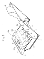
Fig. 1a is a perspective view of a passenger constraining apparatus according to an embodiment.Fig. 1b is a cross-sectional view taken along the line Ib-Ib inFig. 1a . -
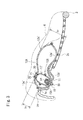
Fig. 2 is a perspective view of a frame of a seat provided with the passenger constraining apparatus according to another embodiment. -
Fig. 3 is a cross-sectional view taken along the line III-III inFig. 2 . - According to a passenger constraining apparatus in the present invention, when an inflator is activated to inject gas in case of emergency such as collision of a vehicle, gas is supplied to the interior of an inner bag from the inflator to inflate the inner bag and the gas in the inflator is flowed out from the gas discharge portions to a seat bag, so that the seat bag is inflated. A seat cushion is pushed upward from below by the inflated seat bag or is hardened by being compressed by the push-up force, so that the forward movement (submarine phenomenon) of a lumber part of a passenger is prevented or restrained.
- In the present invention, the inner bag is rapidly inflated by high-pressure gas supplied from the inflator prior to the seat bag, and then the seat bag is inflated.
- In the present invention, the lower portion of the inner bag is connected to an under-seat-cushion member, and the upper portion thereof is connected to the upper portion of the seat bag, so that the amount of upward inflation of the seat bag is limited by the inner bag.
- In a mode of the present invention, when the seat bag is inflated, the amount of upward inflation of the seat bag on the front end side is limited by the inner bag. Consequently, the seat bag is quickly inflated toward the rear end side of the under-seat-cushion member without being inflated so as to protrude excessively upward.
- In a state in which the seat bag and the inner bag are inflated, a configuration in which a maximum value h1 of the thickness in terms of the vertical direction of the portion of the seat bag where the inner bag is connected (that is, the front end side of the seat bag) is smaller than a maximum value h2 of the thickness in terms of the vertical direction thereof where the inner bag is not connected (that is, the rear end side of the seat bag) is also applicable. Accordingly, the rearward inflation of the seat bag is further encouraged.
- Referring now to the drawings, embodiments of the present invention will be described.
-
Fig. 1a is a perspective view of a passenger constraining apparatus according to an embodiment, andFig. 1b is a cross-sectional view taken along the line Ib-Ib inFig. 1a . In the following description, the lateral direction and fore-and-aft direction represent the direction of lateral width and the fore-and-aft direction of the seat in which the passenger constraining apparatus is installed. - A seat pan 1 is arranged under a seat cushion (not shown) of the seat mounted to a motor vehicle, and a
passenger constraining apparatus 10 is arranged on top of the front portion of the seat pan 1, that is, between the seat cushion and the seat pan 1. - The
passenger constraining apparatus 10 includes aretainer 11 in the shape of a container opened on top, aninflatable seat bag 12 stored in theretainer 11 in a folded state, aninner bag 13 arranged in theseat bag 12, aninflator 14 for inflating theseat bag 12 and theinner bag 13 in case of emergency of the vehicle, afixing member 15 that fixes theseat bag 12, theinner bag 13 and theinflator 14 to theretainer 11, and alid 16 that closes the upper opening of theretainer 11. - The
retainer 11 has a laterally elongated substantially parallelepiped shape, and is arranged on the seat pan 1 with the longitudinal direction thereof directed in the lateral direction. A method of attaching theretainer 11 to the seat is arbitrary. For example, it may be fixed to the seat pan 1 by bolts or the like for example, and may be connected at the both ends thereof to side frames (not shown) on the left and right sides of the seat. In the latter case, the movable unit 1 does not have to be installed. - The upper opening of the
retainer 11 is formed with aflange 11a for securing thelid 16 at the peripheral edge thereof. - The
seat bag 12 extends in the lateral direction in the interior of theretainer 11. In this embodiment, as shown inFig. 1b , theseat bag 12 is a bag-shaped member formed by stitching the peripheral portions of twopanels Reference numeral 12c represents a seam of the stitch. - In this embodiment, the
respective panels panels - The
inner bag 13 is provided substantially at the center of theseat bag 12 in terms of the longitudinal direction. Theinner bag 13 has a smaller capacity than theseat bag 12, and extends in the longitudinal direction of theseat bag 12. In this embodiment, theinner bag 13 is also a bag-shaped member formed by stitching the peripheral portions of twopanels - The
respective panels respective panels aforementioned seat bag 12, and has a similar shape in plan view as therespective panels panels - The
upper side panels seat bag 12 and theinner bag 13 are stitched by aseam 20 at portions near the center in terms of the lateral direction and the fore-and-aft direction.Reference numeral 21 designates a reinforcing cloth placed to the joint portion thereof from the outside of theseat bag 12 and stitched together with thepanels seam 20. - As shown in
Fig. 1b , theupper panel 13a of theinner bag 13 is formed with agas discharge port 17 as a discharge port for allowing gas in theinner bag 13 to flow out into theseat bag 12. In this embodiment, twogas discharge ports 17 are provided. However, the invention is not limited thereto. In this embodiment, thegas discharge ports inner bag 13 with respect to the midsection thereof in terms of the longitudinal direction. The reason thereof will be described later. - The
inflator 14 and thefixing member 15 are provided in the interior of theinner bag 13. Theinflator 14 is a substantially cylindrical member in this embodiment, and is arranged with the axial line thereof directed in parallel to the longitudinal direction of theinner bag 13. In this embodiment, a plurality of gas injection ports (not shown) are provided on the inflator 14 at circumferentially different positions along the side peripheral surface on one side in terms of the axial direction thereof. The inflator 14 is configured to inject gas from the gas injection ports in the radial direction, that is, in the direction of the diameter of theinner bag 13. - The inflator 14 is arranged in such a manner that the end portion thereof provided with the gas injection ports is positioned at one of the both end portions of the
inner bag 13 in terms of the longitudinal direction thereof which is farther from thegas discharge ports 17. With the inflator 14 arranged in this manner, gas injected from the gas injection ports stays in theinner bag 13 for a while without flowing out directly from thegas discharge ports 17 into theseat bag 12. - Accordingly, inflation of the
inner bag 13 is encouraged, and injected gas from the inflator 14 at a high temperature is prevented from blowing directly onto therespective panels seat bag 12 or theseam 12c which joins these panels. - The fixing
member 15 is a plate-shaped member extending along the bottom surface of theretainer 11, and is arranged so as to press thelower panels inner bag 13 and theseat bag 12 against the bottom surface of theretainer 11 from the inner side of theinner bag 13. The fixingmember 15 also serves as an inflator holder and the inflator 14 is held by the fixingmember 15 by acurved bracket portion 15a. - A
stud bolt 18 is provided so as to project from the fixingmember 15. Thestud bolt 18 is inserted through bolt insertion holes (not shown) provided respectively on thepanels retainer 11, and is fixed to theretainer 11 by anut 19 tightened thereto. - Accordingly, the
inner bag 13 and theseat bag 12 are connected to theretainer 11 at the lower portions thereof by the fixingmember 15 and thestud bolt 18. The upper portion of theinner bag 13 is connected to the upper portion of theseat bag 12 by theseam 20 as described above. - The
lid 16 is a substantially rectangular-shaped member for covering the upper opening of theretainer 11, and the peripheral portion thereof is aligned with theflange 11a of theretainer 11 and is secured by a securingmember 16a. A tear line (weakened portion) is extending so as to traverse thelid 16 along the lateral direction and, when theseat bag 12 and theinner bag 13 are inflated, thelid 16 is torn along the tear line due to the inflation pressure thereof and open in the fore-and-aft direction in a flap shape as shown inFig. 1b . - In this embodiment, the dimensions of the inner bag 13 (the length of periphery of the
inner bag 13 near the center, etc.) are set so that the thickness of theinflated seat bag 12 near the center thereof in terms of the vertical direction falls in a range from 50 to 200 mm, more preferably, from 80 to 150 mm. - The operation of the
passenger constraining apparatus 10 in this configuration is as follows. - When front collision of the vehicle is detected, the
inflator 14 is activated and gas is injected from respective gas injection ports 14a into theinner bag 13. Theinner bag 13 is inflated by the gas from the inflator 14, and the gas in theinner bag 13 is flowed out from the respectivegas discharge ports 17 into theseat bag 12 as indicated by an arrow inFig. 1b , so that theseat bag 12 is inflated. The front portion of the seat cushion of the seat is pushed upward by, or hardened by the push-up force of, theinflated seat bag 12, so that the lumber part of the passenger seated on this seat is prevented or restrained from moving toward the front. - In this case, the
inner bag 13 is inflated by high-pressure gas supplied from the inflator 14 prior to theseat bag 12, and then, theseat bag 12 is inflated. - In this
passenger constraining apparatus 10, since the lower portion of theinner bag 13 is connected to theretainer 11, and the upper portion thereof is connected to the upper portion of theseat bag 12, the amount of upward inflation of theseat bag 12 is limited by theinner bag 13. -
Fig. 2 is a perspective view of a frame of a seat provided with a passenger constraining apparatus according to another embodiment, andFig. 3 is a cross-sectional view taken along the line III-III inFig. 2 . - As shown in
Fig. 2 , the frame which constitutes the seat in this embodiment includes a base frame 2 and a back frame 4 rotatably connected to the base frame 2 via a spindle 3 or a reclining device (not shown). A head rest 5 is attached to the upper portion of the back frame 4. The base frame 2 includes left and right side frames 2a, 2b, and aseat pan 1A is provided so as to extend between the front portions of theside frames - In this embodiment, the
seat pan 1A has a width in the fore-and-aft direction which is able to support only the front end side of a seat cushion 6 (Fig. 3 ) disposed on the base frame 2. The rear end side of theseat cushion 6 with respect to theseat pan 1A is supported by springs (S-springs) 2c extending between theseat pan 1A and the spindle 3. - The
springs 2c extend in the fore-and-aft direction in a laterally serpentined pattern and the front ends thereof are secured to the rear ends of theseat pan 1A and the rear ends are secured to the spindle 3. - A
passenger constraining apparatus 10A in this embodiment includes theretainer 11 in the shape of a container opened on top, aninflatable seat bag 12A stored in theretainer 11 in a folded state, aninner bag 13A arranged in theseat bag 12A, theinflator 14 for inflating theseat bag 12A and theinner bag 13A in case of emergency of the vehicle, a fixingmember 15A for fixing theseat bag 12A, theinner bag 13a and the inflator 14 to theretainer 11, and a lid (not shown inFigs. 2 and3 ) that closes the upper opening of theretainer 11. - As shown in
Fig. 3 , theseat bag 12A is configured to be capable of inflating over a relatively wide width in the fore-and-aft direction from the upper side of theseat pan 1A to the upper side of the front half portion of thespring 2c. As shown inFig. 2 , in this embodiment, theseat bag 12A in an inflated state has a shape gradually being narrowed in lateral width from the midsection in terms of the fore-and-aft direction toward the front in plan view. - In this embodiment as well, the
seat bag 12A is a bag-shaped member formed by stitching the peripheral portions of twopanels 12a', 12b' which constitute respectively an upper half side and a lower half side of the outer peripheral surface in an inflated state via a seam (reference numeral is omitted). - As shown in
Fig. 3 , theinner bag 13A has a width in the fore-and-aft direction in an inflated state smaller than half the width of theseat bag 12A in the fore-and-aft direction in an inflated state. Theinner bag 13A is also a bag-shaped member formed by stitching the peripheral portions of twopanels 13a', 13b' which constitute respectively an upper half side and a lower half side of the outer peripheral surface in an inflated state via a seam (reference numeral is omitted). - The
inner bag 13A is arranged at a position relatively close to the front end portion in the interior of theseat bag 12A in an inflated state, and theupper panel 13a' is joined (stitched) to the front portion of theupper side panel 12a' of theseat bag 12A by theseam 20.Reference numeral 21 designates a reinforcing cloth provided at the joint portion. - The
upper panel 13a' of theinner bag 13A is provided with a gas discharge port 17' for allowing gas in theinner bag 13A to flow out into theseat bag 12A at a position which faces rearward when theinner bag 13A is inflated. - The substantially
cylindrical inflator 14 is arranged in theinner bag 13A. The inflator 14 is held by aninflator holder 15A, and thestud bolt 18 is extended from theinflator holder 15A. Thestud bolt 18 is inserted through respective bolt insertion holes (not shown) on thepanels 13b', 12b' and the bottom surface of theretainer 11, and is fixed to theretainer 11 by thenut 19 tightened thereto. - Accordingly, the
inner bag 13A is connected at the lower portion thereof to theretainer 11 by the fixingmember 15 and thestud bolt 18, and is connected at the upper portion to the upper portion of the front end side of theseat bag 12A by theseam 20. - In this embodiment, as shown in
Fig. 3 , the dimensions of theinner bag 13A (the peripheral length of theinner bag 13A) are set so that a maximum value h1 of the thickness in terms of the vertical direction of theseat bag 12A at the front end side (the portion where theinner bag 13A is connected) is smaller than a maximum value h2 of the thickness in terms of the vertical direction of theseat bag 12A at the rear end side (the portion where theinner bag 13A is not connected) in a state in which theseat bag 12A and theinner bag 13A are inflated. - In this embodiment, the
seat bag 12A is folded in such a manner that the width is decreased from the rear end side to the front end side and stored in theretainer 11. - The
passenger constraining apparatus 10A is configured with the lid (not shown inFigs. 2 and3 ) attached to theretainer 11 so as to cover the folded member of theseat bag 12A. - In this embodiment, an opening 1a for installing the passenger constraining apparatus is provided on the
seat pan 1A, and thepassenger constraining apparatus 10A is installed on theseat pan 1A with theretainer 11 fitted into the opening 1a. - Other configurations of the
passenger constraining apparatus 10A are the same as those of thepassenger constraining apparatus 10 inFig. 1 described above, and the reference numerals inFigs. 2 and3 which are the same as those inFig. 1 represent the same parts. - In this embodiment, the
inner bag 13A is inflated quickly by gas from the inflator 14 first, and correspondingly, the front end side of theseat bag 12A is inflated out of theretainer 11, and then the gas in theinner bag 13A flows into theseat bag 12A via the gas discharge port 17', so that theseat bag 12A is inflated and deployed as if it extends rearward. In a state in which theseat bag 12A is completely inflated, the rear portion of theseat bag 12A is positioned above the S-spring 2c. - In the
passenger constraining apparatus 10A, since the amount of upward inflation of the front end side of theseat bag 12A is limited by theinner bag 13A, theseat bag 12A is not inflated so as to protrude upward, and the rearward inflation of theseat bag 12A is encouraged, thereby being inflated from above theseat pan 1A to above thespring 2c in a relatively early stage. - In this embodiment, the dimensions of the
inner bag 13A is set so that a maximum value h1 of the thickness in terms of the vertical direction of theseat bag 12A at the front end side is smaller than a maximum value h2 of the thickness in terms of the vertical direction of theseat bag 12A at the rear end side in a state in which theseat bag 12A and theinner bag 13A are inflated. Therefore, the effect of encouraging the inflation of theseat bag 12A toward the rear is remarkable. - The embodiments shown above are examples of the present invention, and the present invention is not limited to the embodiments shown above.
- For example, the base frame of the seat in the respective embodiments in
Figs. 2 and3 has a structure in which the front end side of the seat cushion is supported by the seat pan and the rear end side with respect to the seat pan is supported by the spring (S-spring). However, needless to say, the present invention is applicable to a structure in which the entire seat cushion (from the front end side to the rear end side of the seat cushion) is supported by the seat pan. - The present application is based on Japanese Patent Application (
Japanese Patent Application No. 2005-325027
Claims (7)
- A passenger constraining apparatus including a seat bag being arranged between a seat cushion and an under-seat-cushion member and being inflatable so as to push the seat cushion from below and an inflator for inflating the seat bag upon emergency of a vehicle comprising:an inner bag being provided in the seat bag and having a smaller capacity than the seat bag,wherein the inflator is installed so as to supply gas into the interior of the inner bag,wherein the lower portion of the inner bag is connected to the under-seat-cushion member andwherein the upper portion of the inner bag is connected to the upper portion of the seat bag.
- The passenger constraining apparatus according to Claim 1, wherein the seat bag is configured to be inflated and deployed from the front end side to the rear end side of the under-seat-cushion member, and the inner bag is arranged on the front end side of the seat bag in an inflated state, and the lower portion of the inner bag is connected to the front end side of the under-seat-cushion member, and the upper portion of the inner bag is connected to the upper portion of the seat bag on the front end side in an inflated state.
- The passenger constraining apparatus according to Claim 2, wherein in a state in which the seat bag and the inner bag are inflated, a maximum value h1 of the thickness in terms of the vertical direction of the portion of the seat bag where the inner bag is connected may be smaller than a maximum value h2 of the thickness in terms of the vertical direction of the portion thereof where the inner bag is not connected.
- The passenger constraining apparatus according to Claim 1, wherein the under-seat-cushion member includes a seat pan and a retainer in which the seat bag is stored, and
wherein the lower portion of the inner bag is connected to the retainer. - The passenger constraining apparatus according to Claim 4, wherein the inflator and a fixing member which holds the inflator are arranged in the interior of the inner bag, and wherein the fixing member and the inner bag and the seat bag are connected to the retainer with a bolt.
- The passenger constraining apparatus according to Claim 4, wherein the under-seat-cushion member further includes an S-spring, and the rear portion of the seat bag is positioned above the S-spring when the seat bag is inflated.
- The passenger constraining apparatus according to Claim 1, wherein the upper portion of the inner bag and the upper portion of the seat bag are connected by stitching.
Applications Claiming Priority (2)
| Application Number | Priority Date | Filing Date | Title |
|---|---|---|---|
| JP2005325027A JP2007131104A (en) | 2005-11-09 | 2005-11-09 | Occupant restraining device |
| PCT/JP2006/321390 WO2007055106A1 (en) | 2005-11-09 | 2006-10-26 | Occupant restraint device |
Publications (1)
| Publication Number | Publication Date |
|---|---|
| EP1892161A1 true EP1892161A1 (en) | 2008-02-27 |
Family
ID=38023112
Family Applications (1)
| Application Number | Title | Priority Date | Filing Date |
|---|---|---|---|
| EP06822359A Withdrawn EP1892161A1 (en) | 2005-11-09 | 2006-10-26 | Occupant restraint device |
Country Status (5)
| Country | Link |
|---|---|
| US (1) | US20090206582A1 (en) |
| EP (1) | EP1892161A1 (en) |
| JP (1) | JP2007131104A (en) |
| CN (1) | CN101213117A (en) |
| WO (1) | WO2007055106A1 (en) |
Cited By (2)
| Publication number | Priority date | Publication date | Assignee | Title |
|---|---|---|---|---|
| DE102007045552A1 (en) * | 2007-09-24 | 2009-04-02 | Autoliv Development Ab | Motor vehicle seat with safety device |
| WO2014028279A1 (en) * | 2012-08-17 | 2014-02-20 | Chrysler Group Llc | Seat cushion airbag |
Families Citing this family (19)
| Publication number | Priority date | Publication date | Assignee | Title |
|---|---|---|---|---|
| JP4998139B2 (en) * | 2007-08-10 | 2012-08-15 | 豊田合成株式会社 | Crew protection device |
| JP5034902B2 (en) * | 2007-11-29 | 2012-09-26 | 豊田合成株式会社 | Airbag device |
| JP5017141B2 (en) * | 2008-02-21 | 2012-09-05 | 日本プラスト株式会社 | Curtain airbag and manufacturing method thereof |
| JP5245707B2 (en) * | 2008-10-14 | 2013-07-24 | 豊田合成株式会社 | Airbag device |
| JP5295820B2 (en) * | 2009-02-26 | 2013-09-18 | 本田技研工業株式会社 | Air bag and air bag device |
| DE102009017919A1 (en) * | 2009-04-16 | 2010-10-21 | Takata-Petri Ag | An airbag assembly for a vehicle occupant restraint system and method of manufacturing an airbag assembly |
| DE102009040246A1 (en) * | 2009-09-02 | 2011-04-07 | Takata-Petri Ag | Airbag module for a vehicle occupant restraint system |
| JP5598354B2 (en) * | 2011-01-28 | 2014-10-01 | 豊田合成株式会社 | Seat cushion airbag device and manufacturing method thereof |
| JP5958129B2 (en) * | 2012-07-12 | 2016-07-27 | 豊田合成株式会社 | Seat cushion airbag device |
| JP5780265B2 (en) * | 2013-06-07 | 2015-09-16 | トヨタ自動車株式会社 | Vehicle seat with built-in cushion airbag device |
| KR102207570B1 (en) * | 2014-09-26 | 2021-01-26 | 현대모비스 주식회사 | Cushion of seat cushion air bag device |
| US20160157617A1 (en) * | 2014-12-04 | 2016-06-09 | Lear Corporation | Thoracic region comfort seating system |
| US10696261B2 (en) * | 2018-12-03 | 2020-06-30 | GM Global Technology Operations LLC | Seat assembly including airbags integrated into a tulip armchair |
| WO2022014207A1 (en) * | 2020-07-14 | 2022-01-20 | オートリブ ディベロップメント エービー | Occupant protection device |
| FR3127449B1 (en) * | 2021-09-29 | 2025-09-05 | Psa Automobiles Sa | Seat frame for vehicle seat with anti-submarining airbag |
| DE102022104440A1 (en) | 2022-02-24 | 2023-08-24 | Autoliv Development Ab | Restraint, restraint assembly and seat unit |
| US12083980B2 (en) * | 2022-06-28 | 2024-09-10 | GM Global Technology Operations LLC | Intelligent seat cushion |
| WO2025004672A1 (en) * | 2023-06-30 | 2025-01-02 | オートリブ ディベロップメント エービー | Occupant protection device |
| WO2026070157A1 (en) * | 2024-09-24 | 2026-04-02 | オートリブ ディベロップメント エービー | Occupant protection device |
Family Cites Families (17)
| Publication number | Priority date | Publication date | Assignee | Title |
|---|---|---|---|---|
| JPH0513656Y2 (en) * | 1985-05-07 | 1993-04-12 | ||
| US4657516A (en) * | 1985-12-09 | 1987-04-14 | Tomas Tassy | Reinflatable life preserver device |
| JPH03281460A (en) * | 1990-03-29 | 1991-12-12 | Mazda Motor Corp | Air bag device for automobile |
| DE19611541C2 (en) * | 1996-03-23 | 1999-05-20 | Daimler Benz Ag | Airbag for motor vehicles |
| US6086092A (en) * | 1998-07-07 | 2000-07-11 | Trw Vehicle Safety Systems Inc. | Inflatable vehicle occupant protection device |
| JP4161705B2 (en) * | 2002-12-19 | 2008-10-08 | タカタ株式会社 | Side airbag and side airbag device |
| JP2004243976A (en) * | 2003-02-17 | 2004-09-02 | Takata Corp | Airbag device for side impact |
| JP4269826B2 (en) * | 2003-03-12 | 2009-05-27 | タカタ株式会社 | Crew protection device |
| JP4034693B2 (en) * | 2003-05-14 | 2008-01-16 | オートリブ株式会社 | Inflator bag and waist or leg restraining device using the inflator bag |
| JP4130206B2 (en) * | 2003-06-24 | 2008-08-06 | オートリブ ディベロップメント エービー | Seat cushion spring holding structure and seat cushion device for vehicle |
| JP4238675B2 (en) * | 2003-08-26 | 2009-03-18 | タカタ株式会社 | Crew protection device |
| JP4534479B2 (en) * | 2003-12-22 | 2010-09-01 | タカタ株式会社 | Airbag device |
| JP4674468B2 (en) * | 2004-02-10 | 2011-04-20 | タカタ株式会社 | Crew protection device |
| JP2005231505A (en) * | 2004-02-19 | 2005-09-02 | Takata Corp | Occupant crash protection device |
| JP2006117219A (en) * | 2004-02-20 | 2006-05-11 | Takata Corp | Occupant crash protection device |
| JP2006199271A (en) * | 2004-12-24 | 2006-08-03 | Tkj Kk | Occupant restraint system |
| JP2007099215A (en) * | 2005-10-07 | 2007-04-19 | Takata Corp | Occupant restraint system |
-
2005
- 2005-11-09 JP JP2005325027A patent/JP2007131104A/en not_active Withdrawn
-
2006
- 2006-10-26 WO PCT/JP2006/321390 patent/WO2007055106A1/en not_active Ceased
- 2006-10-26 EP EP06822359A patent/EP1892161A1/en not_active Withdrawn
- 2006-10-26 CN CNA2006800239247A patent/CN101213117A/en active Pending
- 2006-10-26 US US11/921,518 patent/US20090206582A1/en not_active Abandoned
Non-Patent Citations (1)
| Title |
|---|
| See references of WO2007055106A1 * |
Cited By (2)
| Publication number | Priority date | Publication date | Assignee | Title |
|---|---|---|---|---|
| DE102007045552A1 (en) * | 2007-09-24 | 2009-04-02 | Autoliv Development Ab | Motor vehicle seat with safety device |
| WO2014028279A1 (en) * | 2012-08-17 | 2014-02-20 | Chrysler Group Llc | Seat cushion airbag |
Also Published As
| Publication number | Publication date |
|---|---|
| CN101213117A (en) | 2008-07-02 |
| US20090206582A1 (en) | 2009-08-20 |
| WO2007055106A1 (en) | 2007-05-18 |
| JP2007131104A (en) | 2007-05-31 |
Similar Documents
| Publication | Publication Date | Title |
|---|---|---|
| EP1892161A1 (en) | Occupant restraint device | |
| US11066038B2 (en) | Occupant protection system | |
| CN102470818B (en) | Side airbag device for vehicle | |
| EP2889189B1 (en) | Vehicle side air bag device | |
| JP5186832B2 (en) | Air bag and air bag device | |
| US7695004B2 (en) | Airbag apparatus | |
| CN107531206B (en) | occupant protection device | |
| JP4434193B2 (en) | Side airbag device for vehicle | |
| EP2631126B1 (en) | Rear seat side airbag device | |
| JP4269826B2 (en) | Crew protection device | |
| KR102004535B1 (en) | Rider protection | |
| JP6414157B2 (en) | Vehicle occupant restraint system | |
| US20080129024A1 (en) | Airbag apparatus | |
| US20110012330A1 (en) | Side airbag apparatus | |
| JPH07315156A (en) | Method and device for inflating occupant restraint device for vehicle | |
| US9731634B2 (en) | Seat cushion airbag apparatus | |
| KR20200012832A (en) | Passenger protection device | |
| JP2007210429A (en) | Air belt device for vehicle | |
| US7607728B2 (en) | Passenger constraining apparatus | |
| JP7078742B2 (en) | Vehicle seat | |
| KR102800003B1 (en) | Air bag apparatus for vehicle | |
| US20070080523A1 (en) | Airbag system | |
| JP4603439B2 (en) | Rollover protection device | |
| JP5549577B2 (en) | Side airbag device for rear seats | |
| JP4186997B2 (en) | Energy absorption device for vehicle side |
Legal Events
| Date | Code | Title | Description |
|---|---|---|---|
| PUAI | Public reference made under article 153(3) epc to a published international application that has entered the european phase |
Free format text: ORIGINAL CODE: 0009012 |
|
| 17P | Request for examination filed |
Effective date: 20071219 |
|
| AK | Designated contracting states |
Kind code of ref document: A1 Designated state(s): DE GB |
|
| DAX | Request for extension of the european patent (deleted) | ||
| RBV | Designated contracting states (corrected) |
Designated state(s): DE GB |
|
| STAA | Information on the status of an ep patent application or granted ep patent |
Free format text: STATUS: THE APPLICATION HAS BEEN WITHDRAWN |
|
| 18W | Application withdrawn |
Effective date: 20081127 |