US11066038B2 - Occupant protection system - Google Patents
Occupant protection system Download PDFInfo
- Publication number
- US11066038B2 US11066038B2 US16/568,522 US201916568522A US11066038B2 US 11066038 B2 US11066038 B2 US 11066038B2 US 201916568522 A US201916568522 A US 201916568522A US 11066038 B2 US11066038 B2 US 11066038B2
- Authority
- US
- United States
- Prior art keywords
- seat
- airbag
- occupant
- seatback
- vehicle
- Prior art date
- Legal status (The legal status is an assumption and is not a legal conclusion. Google has not performed a legal analysis and makes no representation as to the accuracy of the status listed.)
- Active, expires
Links
Images


Classifications
-
- B—PERFORMING OPERATIONS; TRANSPORTING
- B60—VEHICLES IN GENERAL
- B60R—VEHICLES, VEHICLE FITTINGS, OR VEHICLE PARTS, NOT OTHERWISE PROVIDED FOR
- B60R21/00—Arrangements or fittings on vehicles for protecting or preventing injuries to occupants or pedestrians in case of accidents or other traffic risks
- B60R21/02—Occupant safety arrangements or fittings, e.g. crash pads
- B60R21/16—Inflatable occupant restraints or confinements designed to inflate upon impact or impending impact, e.g. air bags
- B60R21/20—Arrangements for storing inflatable members in their non-use or deflated condition; Arrangement or mounting of air bag modules or components
- B60R21/207—Arrangements for storing inflatable members in their non-use or deflated condition; Arrangement or mounting of air bag modules or components in vehicle seats
-
- B—PERFORMING OPERATIONS; TRANSPORTING
- B60—VEHICLES IN GENERAL
- B60R—VEHICLES, VEHICLE FITTINGS, OR VEHICLE PARTS, NOT OTHERWISE PROVIDED FOR
- B60R21/00—Arrangements or fittings on vehicles for protecting or preventing injuries to occupants or pedestrians in case of accidents or other traffic risks
- B60R21/02—Occupant safety arrangements or fittings, e.g. crash pads
- B60R21/16—Inflatable occupant restraints or confinements designed to inflate upon impact or impending impact, e.g. air bags
- B60R21/20—Arrangements for storing inflatable members in their non-use or deflated condition; Arrangement or mounting of air bag modules or components
-
- B—PERFORMING OPERATIONS; TRANSPORTING
- B60—VEHICLES IN GENERAL
- B60R—VEHICLES, VEHICLE FITTINGS, OR VEHICLE PARTS, NOT OTHERWISE PROVIDED FOR
- B60R21/00—Arrangements or fittings on vehicles for protecting or preventing injuries to occupants or pedestrians in case of accidents or other traffic risks
- B60R21/02—Occupant safety arrangements or fittings, e.g. crash pads
- B60R21/16—Inflatable occupant restraints or confinements designed to inflate upon impact or impending impact, e.g. air bags
- B60R21/23—Inflatable members
- B60R21/231—Inflatable members characterised by their shape, construction or spatial configuration
- B60R21/233—Inflatable members characterised by their shape, construction or spatial configuration comprising a plurality of individual compartments; comprising two or more bag-like members, one within the other
-
- B—PERFORMING OPERATIONS; TRANSPORTING
- B60—VEHICLES IN GENERAL
- B60N—SEATS SPECIALLY ADAPTED FOR VEHICLES; VEHICLE PASSENGER ACCOMMODATION NOT OTHERWISE PROVIDED FOR
- B60N2/00—Seats specially adapted for vehicles; Arrangement or mounting of seats in vehicles
- B60N2/24—Seats specially adapted for vehicles; Arrangement or mounting of seats in vehicles for particular purposes or particular vehicles
- B60N2/42—Seats specially adapted for vehicles; Arrangement or mounting of seats in vehicles for particular purposes or particular vehicles the seat constructed to protect the occupant from the effect of abnormal g-forces, e.g. crash or safety seats
- B60N2/4207—Seats specially adapted for vehicles; Arrangement or mounting of seats in vehicles for particular purposes or particular vehicles the seat constructed to protect the occupant from the effect of abnormal g-forces, e.g. crash or safety seats characterised by the direction of the g-forces
- B60N2/4214—Seats specially adapted for vehicles; Arrangement or mounting of seats in vehicles for particular purposes or particular vehicles the seat constructed to protect the occupant from the effect of abnormal g-forces, e.g. crash or safety seats characterised by the direction of the g-forces longitudinal
- B60N2/4228—Seats specially adapted for vehicles; Arrangement or mounting of seats in vehicles for particular purposes or particular vehicles the seat constructed to protect the occupant from the effect of abnormal g-forces, e.g. crash or safety seats characterised by the direction of the g-forces longitudinal due to impact coming from the rear
-
- B—PERFORMING OPERATIONS; TRANSPORTING
- B60—VEHICLES IN GENERAL
- B60N—SEATS SPECIALLY ADAPTED FOR VEHICLES; VEHICLE PASSENGER ACCOMMODATION NOT OTHERWISE PROVIDED FOR
- B60N2/00—Seats specially adapted for vehicles; Arrangement or mounting of seats in vehicles
- B60N2/24—Seats specially adapted for vehicles; Arrangement or mounting of seats in vehicles for particular purposes or particular vehicles
- B60N2/42—Seats specially adapted for vehicles; Arrangement or mounting of seats in vehicles for particular purposes or particular vehicles the seat constructed to protect the occupant from the effect of abnormal g-forces, e.g. crash or safety seats
- B60N2/427—Seats or parts thereof displaced during a crash
- B60N2/42727—Seats or parts thereof displaced during a crash involving substantially rigid displacement
- B60N2/42745—Seats or parts thereof displaced during a crash involving substantially rigid displacement of the back-rest
-
- B—PERFORMING OPERATIONS; TRANSPORTING
- B60—VEHICLES IN GENERAL
- B60N—SEATS SPECIALLY ADAPTED FOR VEHICLES; VEHICLE PASSENGER ACCOMMODATION NOT OTHERWISE PROVIDED FOR
- B60N2/00—Seats specially adapted for vehicles; Arrangement or mounting of seats in vehicles
- B60N2/24—Seats specially adapted for vehicles; Arrangement or mounting of seats in vehicles for particular purposes or particular vehicles
- B60N2/42—Seats specially adapted for vehicles; Arrangement or mounting of seats in vehicles for particular purposes or particular vehicles the seat constructed to protect the occupant from the effect of abnormal g-forces, e.g. crash or safety seats
- B60N2/427—Seats or parts thereof displaced during a crash
- B60N2/42772—Seats or parts thereof displaced during a crash characterised by the triggering system
- B60N2/4279—Seats or parts thereof displaced during a crash characterised by the triggering system electric or electronic triggering
-
- B—PERFORMING OPERATIONS; TRANSPORTING
- B60—VEHICLES IN GENERAL
- B60R—VEHICLES, VEHICLE FITTINGS, OR VEHICLE PARTS, NOT OTHERWISE PROVIDED FOR
- B60R21/00—Arrangements or fittings on vehicles for protecting or preventing injuries to occupants or pedestrians in case of accidents or other traffic risks
- B60R21/02—Occupant safety arrangements or fittings, e.g. crash pads
- B60R21/16—Inflatable occupant restraints or confinements designed to inflate upon impact or impending impact, e.g. air bags
- B60R21/20—Arrangements for storing inflatable members in their non-use or deflated condition; Arrangement or mounting of air bag modules or components
- B60R21/205—Arrangements for storing inflatable members in their non-use or deflated condition; Arrangement or mounting of air bag modules or components in dashboards
-
- B—PERFORMING OPERATIONS; TRANSPORTING
- B60—VEHICLES IN GENERAL
- B60R—VEHICLES, VEHICLE FITTINGS, OR VEHICLE PARTS, NOT OTHERWISE PROVIDED FOR
- B60R21/00—Arrangements or fittings on vehicles for protecting or preventing injuries to occupants or pedestrians in case of accidents or other traffic risks
- B60R21/02—Occupant safety arrangements or fittings, e.g. crash pads
- B60R21/16—Inflatable occupant restraints or confinements designed to inflate upon impact or impending impact, e.g. air bags
- B60R21/23—Inflatable members
- B60R21/231—Inflatable members characterised by their shape, construction or spatial configuration
- B60R21/2334—Expansion control features
-
- B—PERFORMING OPERATIONS; TRANSPORTING
- B60—VEHICLES IN GENERAL
- B60R—VEHICLES, VEHICLE FITTINGS, OR VEHICLE PARTS, NOT OTHERWISE PROVIDED FOR
- B60R21/00—Arrangements or fittings on vehicles for protecting or preventing injuries to occupants or pedestrians in case of accidents or other traffic risks
- B60R21/02—Occupant safety arrangements or fittings, e.g. crash pads
- B60R21/16—Inflatable occupant restraints or confinements designed to inflate upon impact or impending impact, e.g. air bags
- B60R21/23—Inflatable members
- B60R21/239—Inflatable members characterised by their venting means
-
- B—PERFORMING OPERATIONS; TRANSPORTING
- B60—VEHICLES IN GENERAL
- B60R—VEHICLES, VEHICLE FITTINGS, OR VEHICLE PARTS, NOT OTHERWISE PROVIDED FOR
- B60R21/00—Arrangements or fittings on vehicles for protecting or preventing injuries to occupants or pedestrians in case of accidents or other traffic risks
- B60R21/02—Occupant safety arrangements or fittings, e.g. crash pads
- B60R21/16—Inflatable occupant restraints or confinements designed to inflate upon impact or impending impact, e.g. air bags
- B60R21/26—Inflatable occupant restraints or confinements designed to inflate upon impact or impending impact, e.g. air bags characterised by the inflation fluid source or means to control inflation fluid flow
- B60R21/276—Inflatable occupant restraints or confinements designed to inflate upon impact or impending impact, e.g. air bags characterised by the inflation fluid source or means to control inflation fluid flow with means to vent the inflation fluid source, e.g. in case of overpressure
-
- B—PERFORMING OPERATIONS; TRANSPORTING
- B60—VEHICLES IN GENERAL
- B60R—VEHICLES, VEHICLE FITTINGS, OR VEHICLE PARTS, NOT OTHERWISE PROVIDED FOR
- B60R21/00—Arrangements or fittings on vehicles for protecting or preventing injuries to occupants or pedestrians in case of accidents or other traffic risks
- B60R2021/0002—Type of accident
- B60R2021/0011—Rear collision or recoiling bounce after frontal collision
-
- B—PERFORMING OPERATIONS; TRANSPORTING
- B60—VEHICLES IN GENERAL
- B60R—VEHICLES, VEHICLE FITTINGS, OR VEHICLE PARTS, NOT OTHERWISE PROVIDED FOR
- B60R21/00—Arrangements or fittings on vehicles for protecting or preventing injuries to occupants or pedestrians in case of accidents or other traffic risks
- B60R2021/003—Arrangements or fittings on vehicles for protecting or preventing injuries to occupants or pedestrians in case of accidents or other traffic risks characterised by occupant or pedestian
- B60R2021/0039—Body parts of the occupant or pedestrian affected by the accident
- B60R2021/0048—Head
-
- B—PERFORMING OPERATIONS; TRANSPORTING
- B60—VEHICLES IN GENERAL
- B60R—VEHICLES, VEHICLE FITTINGS, OR VEHICLE PARTS, NOT OTHERWISE PROVIDED FOR
- B60R21/00—Arrangements or fittings on vehicles for protecting or preventing injuries to occupants or pedestrians in case of accidents or other traffic risks
- B60R21/02—Occupant safety arrangements or fittings, e.g. crash pads
- B60R21/16—Inflatable occupant restraints or confinements designed to inflate upon impact or impending impact, e.g. air bags
- B60R21/23—Inflatable members
- B60R21/231—Inflatable members characterised by their shape, construction or spatial configuration
- B60R2021/23153—Inflatable members characterised by their shape, construction or spatial configuration specially adapted for rear seat passengers
-
- B—PERFORMING OPERATIONS; TRANSPORTING
- B60—VEHICLES IN GENERAL
- B60R—VEHICLES, VEHICLE FITTINGS, OR VEHICLE PARTS, NOT OTHERWISE PROVIDED FOR
- B60R21/00—Arrangements or fittings on vehicles for protecting or preventing injuries to occupants or pedestrians in case of accidents or other traffic risks
- B60R21/02—Occupant safety arrangements or fittings, e.g. crash pads
- B60R21/16—Inflatable occupant restraints or confinements designed to inflate upon impact or impending impact, e.g. air bags
- B60R21/23—Inflatable members
- B60R21/231—Inflatable members characterised by their shape, construction or spatial configuration
- B60R21/233—Inflatable members characterised by their shape, construction or spatial configuration comprising a plurality of individual compartments; comprising two or more bag-like members, one within the other
- B60R2021/23324—Inner walls crating separate compartments, e.g. communicating with vents
Definitions
- the disclosure relates to an occupant protection system.
- JP 2008-222154 A describes an occupant protection system configured such that an airbag is disposed on a rear side of an upper part of a seatback in a rear seat.
- the occupant protection system is configured such that, when the airbag inflates and deploys between the seatback and a headrest at the time of a collision at the rear side in the vehicle front-rear direction, a resistance is given to displacement of the headrest toward the rear side in the vehicle front-rear direction.
- the occupant protection system in JP 2008-222154 A is provided to protect the head of an occupant by the headrest at the time of a collision at the rear side in the vehicle front-rear direction and no consideration is given to reducing an impact to the chest. Further, in order to deal with a whiplash injury evaluation carried out for collision assessment in various countries, the occupant protection system is targeted for a case where a vehicle has a minor rear collision particularly in a direction from straight behind the vehicle, that is, a collision direction is a direction from straight behind the vehicle. Therefore, no consideration is given to protecting the head in a case where the collision direction is an oblique direction with respect to the vehicle and the head of the occupant moves away from the headrest.
- the disclosure provides an occupant protection system configured to reduce an impact received by an occupant in case of a collision that causes the occupant to inertially move rearward in the seat front-rear direction.
- An occupant protection system includes a seat disposed such that a rear surface of a seatback in a seat front-rear direction faces a wall portion of a vehicle cabin; an airbag provided in the wall portion or the seatback and configured to support the seatback by inflating and deploying between the wall portion and the seatback; and an inflator configured to generate gas to be supplied to the airbag in a case where a collision that causes an occupant seated in the seat to inertially move rearward in the seat front-rear direction is detected or predicted.
- the airbag has a vent hole through which the gas inside the airbag is discharged outside.
- the airbag inflates and deploys between the wall portion of the vehicle cabin and the seatback.
- a collision that causes an occupant seated in the seat to inertially move rearward in the seat front-rear direction indicates a collision at the front side in the vehicle front-rear direction in the case of a vehicle including a seat provided such that an occupant faces rearward, or a collision at the rear side in the vehicle front-rear direction in the case of a vehicle including a seat provided such that an occupant faces forward.
- the airbag supports the occupant via the seatback.
- the vent hole is provided in the airbag so as to restrain the internal pressure of the airbag from becoming excessively large due to the gas.
- the collision of the vehicle is ended without applying an excessive load to the chest of the occupant. That is, with the occupant protection system of the above aspect, an impact to the chest of the occupant is reduced in case of a collision that causes the occupant to inertially move rearward in the seat front-rear direction.
- the airbag may inflate and deploy in an area of the seatback, the area corresponding to a chest of the occupant; and the airbag may inflate and deploy outwardly in a seat width direction beyond a headrest of the seat at a time when the occupant moves maximally.
- the airbag inflates and deploys so as to protrude outwardly in the seat width direction from the headrest. That is, with the occupant protection system, even in a case where the vehicle has a collision in an oblique direction (i.e., an object (e.g., another vehicle) obliquely collides with the vehicle) and the head of the occupant cannot be supported by the headrest at the time when the occupant moves maximally, an impact to the head can be reduced by the airbag.
- an oblique direction i.e., an object (e.g., another vehicle) obliquely collides with the vehicle
- the vent hole may be provided on a side face of the airbag in a seat width direction so as to be disposed between the seat and a windshield at a time when the occupant moves maximally.
- the vent hole is not closed even at the time when the airbag inflates and deploys and the occupant moves maximally. Accordingly, with the occupant protection system, it is possible to secure a function to reduce the impact received by the occupant.
- the airbag may include a seat deployment portion configured to support the seat including the seatback; an upper deployment portion connected to an upper side of the seat deployment portion in a seat up-down direction and having the vent hole, the upper deployment portion being configured to inflate and deploy in an area above a head of the occupant in the seat up-down direction; a partition wall configured to separate the seat deployment portion from the upper deployment portion; and a check valve provided in the partition wall and configured to permit only a flow of the gas from the seat deployment portion to the upper deployment portion.
- the occupant protection system having the above-described configuration includes the upper deployment portion configured to inflate and deploy in the area above the head of the occupant in the seat up-down direction, in addition to the seat deployment portion configured to support the seatback.
- the upper deployment portion inflates and deploys due to the gas flowing into the upper deployment portion from the check valve. Further, the upper deployment portion has the vent hole, and thus, the internal pressure of the airbag is restrained from becoming excessively large due to the gas.
- the upper deployment portion can restrain the head of the occupant without causing an excessive load to be applied to the head of the occupant.
- the partition wall may be provided so as to be disposed between the seat and a windshield at a time when the seat deployment portion inflates and deploys.
- the check valve provided in the partition wall is not closed even at the time when the seat deployment portion inflates and deploys, thereby making it possible to secure a function to reduce the impact received by the occupant.
- the vent hole may be provided on a side face of the upper deployment portion in a seat width direction so as to be disposed between the head and a windshield at a time when the occupant moves maximally.
- the vent hole is not closed even at the time when the occupant moves maximally, thereby making it possible to secure a function to protect the head of the occupant.
- the inflator and the airbag before inflating and deploying may be stored inside the seatback.
- the airbag is provided in the seatback, and therefore, even in a case where the vehicle has a collision in an oblique direction and the seatback moves obliquely rearward in the seat front-rear direction, the airbag can support the seatback.
- the inflator and the airbag before inflating and deploying may be stored inside the wall portion.
- the airbag and the inflator are eliminated from the seatback, and accordingly, the weight of the seat can be reduced. Therefore, it is possible to reduce a load input into the wall portion from the seat.
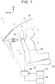
- FIG. 1 is a side view of a vehicle and illustrates the arrangement of an occupant protection system according to first and second embodiments;
- FIG. 2 is a rear view of a front seat and illustrates a state where a rear airbag and an inflator are stored in the occupant protection system according to the first and second embodiments;
- FIG. 3A is a side view of a vehicle in a state where the rear airbag is inflating and deploying in the occupant protection system according to the first embodiment
- FIG. 3B is a front view of the front seat in the state where the rear airbag is inflating and deploying in the occupant protection system according to the first embodiment;
- FIG. 4A is a side view of the vehicle in a state after the rear airbag has inflated and deployed in the occupant protection system according to the first embodiment
- FIG. 4B is a front view of the front seat in the state after the rear airbag has inflated and deployed in the occupant protection system according to the first embodiment
- FIG. 5 is a side view of the vehicle in a state where the rear airbag is inflating and deploying in the occupant protection system according to the second embodiment;
- FIG. 6 is a side view of the vehicle in a state after the rear airbag has inflated and deployed in the occupant protection system according to the second embodiment
- FIG. 7A is a plan sectional view taken along a line VIIA-VIIA in FIG. 7B , and illustrates the state after the rear airbag has inflated and deployed in the occupant protection system according to the second embodiment;
- FIG. 7B is a front view of the front seat in the state after the rear airbag has inflated and deployed in the occupant protection system according to the second embodiment;
- FIG. 8 is a side view of a vehicle and illustrates the arrangement of an occupant protection system according to a third embodiment
- FIG. 9A is a side view of the vehicle in a state where the rear airbag is inflating and deploying in the occupant protection system according to the third embodiment;
- FIG. 9B is a front view of the front seat in the state where the rear airbag is inflating and deploying in the occupant protection system according to the third embodiment;
- FIG. 10A is a side view of the vehicle in a state after the rear airbag has inflated and deployed in the occupant protection system according to the third embodiment.
- FIG. 10B is a front view of the front seat in the state after the rear airbag has inflated and deployed in the occupant protection system according to the third embodiment.
- an arrow FR indicates the front side in the vehicle front-rear direction
- an arrow UP indicates the upper side in the vehicle up-down direction
- an arrow RH indicates the right side in the vehicle width direction.
- the rear side in the seat front-rear direction corresponds to the front side in the vehicle front-rear direction
- the upper side in the seat up-down direction corresponds to the upper side in the vehicle up-down direction
- the left side in the seat width direction corresponds to the right side in the vehicle width direction.
- FIG. 1 illustrates a vehicle 12 to which an occupant protection system 10 according to the present embodiment is applied.
- the vehicle 12 of the present embodiment is an autonomous vehicle and does not require a driver during autonomous driving.
- a front windshield glass (hereinafter just referred to as “windshield”) 16 as a windshield and a dashboard 18 are disposed in the front side, in the vehicle front-rear direction, of a vehicle cabin 14 of the vehicle 12 .
- the windshield 16 is disposed between a pair of pillars (not shown) provided in the vehicle width direction.
- the windshield 16 is inclined downward in the vehicle up-down direction toward the front side in the vehicle front-rear direction.
- the dashboard 18 includes an upper wall portion 18 A extending toward the rear side in the vehicle front-rear direction along the vehicle front-rear direction from the vicinity of a bottom end of the windshield 16 , and a rear wall portion 18 B that is a wall portion inclined downward in the vehicle up-down direction toward the rear side in the vehicle front-rear direction from a rear end of the upper wall portion 18 A in the vehicle front-rear direction.
- the vehicle cabin 14 is provided with a front seat 20 that is a seat facing rearward in the vehicle front-rear direction so as to face a rear seat (not shown) facing forward in the vehicle front-rear direction.
- a front seat 20 that is a seat facing rearward in the vehicle front-rear direction so as to face a rear seat (not shown) facing forward in the vehicle front-rear direction.
- the occupant P thus seated in the front seat 20 faces rearward in the vehicle front-rear direction.
- the occupant protection system 10 of the present embodiment includes the front seat 20 and an airbag device 30 .
- the front seat 20 includes a seat cushion 22 that allows the occupant P to be seated thereon by supporting the thighs and the buttocks of the occupant P, a seatback 24 that can support the back of the occupant P, and a headrest 26 that can support the head H of the occupant P.
- the seat cushion 22 includes a cushion material made of urethane foam, and a covering material made of cloth or leather and covering the surface of the cushion material.
- the seat cushion 22 is formed to be slidable in the vehicle front-rear direction via a seat rail (not shown). Note that the seat cushion 22 may be formed to be rotatable around an axis extending along the vehicle up-down direction.
- the seatback 24 includes a pair of right and left side frames 24 A provided so as to extend in the height direction, and an upper frame 24 B connected to respective upper end portions of the side frames 24 A in the seat up-down direction so as to extend in the seat width direction. Further, the seatback 24 includes a cushion material provided for the side frames 24 A and the upper frame 24 B and made of urethane foam, and a covering material made of cloth or leather and covering the surface of the cushion material.
- lower end portions of the side frames 24 A in the seat up-down direction are pivotally supported in the vicinity of a rear end portion of the seat cushion 22 in the seat front-rear direction, so that the seatback 24 is formed to be pivotable in the seat front-rear direction (see an arrow R in FIG. 4A ).
- the seatback 24 of the present embodiment is disposed so that a rear surface of the seatback 24 in the seat front-rear direction faces the rear wall portion 18 B that is a wall portion of the vehicle cabin 14 .
- a plate-shaped back panel 24 C is connected to rear surfaces of the side frames 24 A in the seat front-rear direction.
- the airbag device 30 is fixed to the back panel 24 C.
- a pair of right and left holders 24 D is connected to the vicinity of the center of the upper frame 24 B in the seat width direction.
- the holder 24 D is formed into a cylindrical shape, and a headrest stay 26 A (described below) is inserted into the holder 24 D.
- a headrest 26 is provided in an upper end portion of the seatback 24 in the seat up-down direction.
- the headrest 26 includes a cushion material made of urethane foam, and a covering material made of cloth or leather and covering the surface of the cushion material. Further, the headrest 26 includes the pair of right and left headrest stays 26 A extending downward in the seat up-down direction. When the headrest stays 26 A are inserted into the holders 24 D provided in the upper end portion of the seatback 24 in the seat up-down direction, respectively, the headrest 26 is fixed so as to be slidable in the seat up-down direction relative to the seatback 24 .
- the airbag device 30 includes a rear airbag 32 as an airbag, an inflator 36 configured to supply gas to the rear airbag 32 , and an electronic control unit (ECU) 50 configured to control the operation of the inflator 36 .
- the airbag device 30 is configured to support the seatback 24 of the front seat 20 that pivots rearward in the seat front-rear direction (forward in the vehicle front-rear direction) when the vehicle 12 has a collision at the front side in the vehicle front-rear direction (i.e., when an object (e.g., another vehicle) collides with the front side of the vehicle 12 in the vehicle front-rear direction).
- the rear airbag 32 and the inflator 36 are stored inside the seatback 24 .
- the rear airbag 32 of the present embodiment inflates and deploys between the rear wall portion 18 B and the seatback 24 .
- the rear airbag 32 is formed in a bag shape by overlapping two sheets of base cloth made of a nylon or polyester fabric material, and sewing them together.
- the rear airbag 32 inflates and deploys in an area in the seatback 24 , the area corresponding to the chest C of the occupant P (see FIGS. 4A and 4B ).
- the rear airbag 32 inflates and deploys outwardly in the seat width direction beyond the headrest 26 at the time when the occupant P moves maximally (see FIG. 4B ).
- the rear airbag 32 before inflating and deploying is in a folded state and is stored inside the seatback 24 .
- the rear airbag 32 is stored in a reverse L-shape in a rear view.
- the rear airbag 32 inflates and deploys from the seatback 24 toward the rear wall portion 18 B (see FIG. 3A ).
- the rear airbag 32 further inflates and deploys toward the lower side of the seatback 24 in the seat up-down direction and toward an area above the headrest 26 in the seat up-down direction (see FIG. 4A ), and the rear airbag 32 also inflates and deploys outwardly in the seat width direction (see FIGS. 3B, 4B ).
- FIG. 3A the rear airbag 32
- the rear airbag 32 inflates and deploys between the rear wall portion 18 B and the seatback 24 , and thus, the rear airbag 32 supports the seatback 24 and the headrest 26 that pivot rearward (an arrow-R direction) in the seat front-rear direction upon receipt of a load from the occupant.
- vent holes 34 are provided in the rear airbag 32 .
- Each of the vent holes 34 is a round hole through which gas inside the rear airbag 32 is discharged outside.
- the vent hole 34 is provided in each side face (a surface on each side in the seat width direction) of the rear airbag 32 . Further, in a side view, the vent hole 34 is provided so as to be disposed between the front seat 20 and the windshield 16 at the time when the occupant P moves maximally.
- the inflator 36 is configured to generate gas to be supplied to the rear airbag 32 in a case where a collision that causes the occupant P seated in the front seat 20 to inertially move rearward in the seat front-rear direction is detected or predicted.
- a case where the vehicle 12 has a collision at the front side in the vehicle front-rear direction corresponds to a case where “a collision that causes the occupant P to inertially move rearward is detected.”
- a case where the vehicle 12 is likely to have a collision at the front side in the vehicle front-rear direction corresponds to a case where “a collision that causes the occupant P to inertially move rearward is predicted.” As illustrated in FIG.
- the inflator 36 of the present embodiment is formed in a substantially cylindrical shape with its longitudinal direction extending along the seat up-down direction.
- a plate-shaped holding plate 24 E is fixed to the back panel 24 C with bolts 24 F, and the inflator 36 is sandwiched between the back panel 24 C and the holding plate 24 E so as to be fixed to the seatback 24 .
- a cylindrical extending portion 33 extends downward in the seat up-down direction from a right end portion of the rear airbag 32 in the seat width direction, and the upper side of the inflator 36 in the seat up-down direction is inserted into the extending portion 33 .
- a gas injection portion 38 including a plurality of holes is formed in an insertion part of the inflator 36 , which is inserted into the extending portion 33 .
- the ECU 50 is electrically connected to the inflator 36 .
- the ECU 50 is configured to control the operation of the inflator 36 .
- the ECU 50 is electrically connected to a collision prediction sensor 52 such as a pre-collision sensor or an in-vehicle camera that is configured to predict a collision.
- the ECU 50 is electrically connected to a collision sensor 54 configured to detect a collision.
- the ECU 50 operates the inflator 36 .
- the volume of the rear airbag 32 , the diameter of the vent hole 34 , the amount of gas to be supplied from the inflator 36 , and so on are adjusted in a range where the seatback 24 does not hit the rear wall portion 18 B at the time when the occupant P moves maximally.
- the rear airbag 32 before inflating and deploying is stored inside the seatback 24 , and the seatback 24 is distanced from the dashboard 18 .
- the collision prediction sensor 52 predicts a collision
- the collision prediction sensor 52 outputs a signal to the ECU 50 .
- the collision sensor 54 detects a collision
- the collision sensor 54 outputs a signal to the ECU 50 .
- the ECU 50 receives the signal from at least one of the collision prediction sensor 52 and the collision sensor 54
- the ECU 50 outputs a signal to the inflator 36 .
- the inflator 36 When the inflator 36 receives the signal from the ECU 50 , an ignition agent provided inside the inflator 36 is ignited. Thus, gas is generated inside the inflator 36 , and the gas is emitted from the gas injection portion 38 .
- the gas emitted from the gas injection portion 38 is supplied into the rear airbag 32 .
- the rear airbag 32 starting inflating splits a tear line (not shown) as a fragile portion provided on the rear side of the seatback 24 in the seat front-rear direction, and thus, the rear airbag 32 inflates and deploys in an area behind the seatback 24 in the seat front-rear direction. Then, the rear airbag 32 makes contact with the rear wall portion 18 B of the dashboard 18 .
- the vent hole 34 closed in the rear airbag 32 folded before inflating and deploying appears on the side face of the rear airbag 32 .
- the gas supplied into the rear airbag 32 is partially discharged via the vent hole 34 , thereby restraining the internal pressure of the rear airbag 32 from becoming excessively large. This restrains an excessive load from being applied to the seatback 24 from the rear airbag 32 .
- the rear airbag 32 that is inflating and deploying has a substantially triangular shape in a front view and is positioned within a range from the substantially center of the seatback 24 in the seat up-down direction to the substantially center of the headrest 26 in the seat up-down direction.
- the rear airbag 32 when the gas emitted from the gas injection portion 38 is continuously supplied into the rear airbag 32 , the rear airbag 32 further inflates and deploys. Further, the rear airbag 32 is compressed by the seatback 24 and the headrest 26 that pivot rearward (the arrow-R direction) in the seat front-rear direction upon receipt of a load from the occupant P. At this time, the lower side of the rear airbag 32 in the seat up-down direction is sandwiched between the seatback 24 and the rear wall portion 18 B, and the upper side of the rear airbag 32 in the seat up-down direction is sandwiched between the headrest 26 and the windshield 16 .
- the gas inside the rear airbag 32 is discharged moderately through the vent hole 34 . This restrains an excessive load from being applied to the seatback 24 from the rear airbag 32 .
- the collision of the vehicle 12 is ended without excessively applying a load to the chest C of the occupant P.
- the rear airbag 32 after inflating and deploying has a substantially triangular shape in a front view and covers a range from the substantially center of the seatback 24 in the seat up-down direction to an upper end portion of the headrest 26 in the seat up-down direction.
- an outer part of the rear airbag 32 in the seat width direction protrudes from the seatback 24 .
- the outer part of the rear airbag 32 in the seat width direction and an upper part of the rear airbag 32 in the seat up-down direction protrude from the headrest 26 .
- a collision speed which is a relative speed during the collision, is higher when another vehicle collides with the front side of a host vehicle in the vehicle front-rear direction than a collision speed when the other vehicle collides with the rear side of the host vehicle in the vehicle front-rear direction, a direction toward the front side being a traveling direction of the host vehicle, and a direction toward the rear side being opposite to the traveling direction of the host vehicle.
- the present embodiment employs the above configuration to deal with a high collision speed.
- the rear airbag 32 supports the occupant P via the seatback 24 and the headrest 26 .
- a load is restrained from being excessively applied to the chest C of the occupant P.
- an impact to the chest C of the occupant P is reduced in case of a collision that causes the occupant P to inertially move rearward in the seat front-rear direction.
- the occupant protection system 10 of the present embodiment it is possible to reduce the mass of the front seat 20 in comparison with a case where the seatback 24 is restrained from hitting the rear wall portion 18 B by increasing the strength of the seat cushion 22 and the seatback 24 . That is, it is also possible to achieve a reduction in the weight of the vehicle 12 .
- the rear airbag 32 inflates and deploys so as to protrude from the headrest 26 , so that the following effects can be yielded. That is, with the occupant protection system 10 of the present embodiment, even in a case where the vehicle 12 has a collision in an oblique direction (i.e., an object (e.g., another vehicle) obliquely collides with the vehicle 12 ) and the head H of the occupant P cannot be supported by the headrest 26 at the time when the occupant P moves maximally, an impact to the head H can be reduced by the rear airbag 32 .
- an oblique direction i.e., an object (e.g., another vehicle) obliquely collides with the vehicle 12
- an impact to the head H can be reduced by the rear airbag 32 .
- the vent hole 34 is provided so as to appear between the front seat 20 (the seatback 24 and the headrest 26 ) and the windshield 16 even when the occupant P moves maximally. That is, it is desirable that the vent hole 34 be disposed in a part that has a sufficient length in the vehicle front-rear direction, the part being located between the rear wall portion 18 B and the seatback 24 . With the occupant protection system 10 of the present embodiment, the vent hole 34 is not closed even at the time when the occupant P moves maximally, thereby making it possible to secure a function to reduce the impact to the chest C and the head H of the occupant P.
- the airbag device 30 is provided on the seatback 24 -side (i.e., the airbag device 30 is provided in the seatback 24 ). Accordingly, even in a case where the vehicle 12 has an oblique collision at the front side in the vehicle front-rear direction (i.e., an object (e.g., another vehicle) obliquely collides with the front side of the vehicle 12 ) and the seatback 24 moves obliquely rearward in the seat front-rear direction, the rear airbag 32 can support the seatback 24 and the headrest 26 .
- the rear airbag 32 of the present embodiment supports the seatback 24 and the headrest 26 at the time of a collision, but when at least the seatback 24 can be supported, it is possible to reduce an impact to the chest C of the occupant P.
- An occupant protection system 10 A of the second embodiment is different from the occupant protection system 10 of the first embodiment in the shape of the rear airbag.
- an airbag device 30 A of the occupant protection system 10 A of the present embodiment includes a rear airbag 32 A and the inflator 36 .
- the rear airbag 32 A includes a seat deployment portion 40 configured to inflate and deploy in an area behind the seatback 24 and the headrest 26 in the seat front-rear direction, and an upper deployment portion 42 configured to inflate and deploy in an area above the headrest 26 in the seat up-down direction.
- the upper deployment portion 42 is connected to an upper side of the seat deployment portion 40 in the seat up-down direction.
- the rear airbag 32 A of the present embodiment is formed to have a bag shape in which the seat deployment portion 40 and the upper deployment portion 42 are integrated, by overlapping two sheets of base cloth made of a nylon or polyester fabric material, and sewing them together.
- a partition wall 44 configured to separate the seat deployment portion 40 from the upper deployment portion 42
- a check valve 46 provided in the partition wall 44 and configured to permit only the flow of gas from the seat deployment portion 40 to the upper deployment portion 42 are provided inside the rear airbag 32 A.
- the partition wall 44 and the check valve 46 are made of a fabric material similar to the material of the rear airbag 32 A. Further, in a side view, the partition wall 44 and the check valve 46 are provided so as to be disposed between the front seat 20 and the windshield 16 at the time when the seat deployment portion 40 inflates and deploys.
- the check valve 46 is formed by sewing a fabric material formed in a cylindrical shape to a communicating opening 44 A provided in the partition wall 44 .
- a first opening end of the cylindrical check valve 46 is sewn to an edge of the communicating opening 44 A in the partition wall 44 .
- a second opening end of the check valve 46 projects into the upper deployment portion 42 , thereby allowing the gas to flow from the seat deployment portion 40 to the upper deployment portion 42 .
- the check valve 46 is configured to restrict the flow of the gas from the upper deployment portion 42 to the seat deployment portion 40 by being compressed when the internal pressure of the upper deployment portion 42 becomes higher than the internal pressure of the seat deployment portion 40 .
- This restriction includes a case where the flow of the gas is completely stopped and a case where the flow of the gas is reduced.
- the vent hole 34 is provided in each side face (a surface on each side in the seat width direction) of the upper deployment portion 42 . Further, the vent hole 34 is provided so as to be closer to the occupant P than the headrest 26 is, and to be between the head H of the occupant P and the windshield 16 at the time when the occupant P moves maximally (see FIG. 6 ).
- the seat deployment portion 40 of the present embodiment has substantially the same shape as that of the rear airbag 32 of the first embodiment, and the seat deployment portion 40 inflates and deploys in an area in the seatback 24 , the area corresponding to the chest C of the occupant P, similarly to the rear airbag 32 . That is, the seat deployment portion 40 of the present embodiment is a part of the rear airbag 32 A, which supports the front seat 20 including the seatback 24 . Further, as illustrated in FIGS. 7A, 7B , the seat deployment portion 40 inflates and deploys outwardly in the seat width direction beyond the headrest 26 at the time when the occupant P moves maximally.
- the upper deployment portion 42 inflates and deploys to reach an area ahead of the head H in the seat front-rear direction along the windshield 16 in an area above the head H in the seat up-down direction.
- the upper deployment portion 42 can support the head H moving upward in the seat up-down direction.
- the rear airbag 32 A before inflating and deploying is stored inside the seatback 24 , and the seatback 24 is distanced from the dashboard 18 , similarly to the first embodiment (see FIG. 1 ).
- gas is emitted from the gas injection portion 38 in the inflator 36 .
- the gas emitted from the gas injection portion 38 is first supplied into the seat deployment portion 40 .
- the seat deployment portion 40 starting inflating splits a tear line (not shown) as a fragile portion provided on the rear side of the seatback 24 in the seat front-rear direction in a side view, so that the seat deployment portion 40 inflates and deploys in the area behind the seatback 24 in the seat front-rear direction. Then, the seat deployment portion 40 makes contact with the rear wall portion 18 B of the dashboard 18 .
- the partition wall 44 and the check valve 46 folded together with the upper deployment portion 42 before inflating and deploying appear inside the rear airbag 32 A. Then, the gas supplied into the seat deployment portion 40 partially flows into the upper deployment portion 42 from the check valve 46 , so that the upper deployment portion 42 starts inflating.
- the internal pressure of the seat deployment portion 40 is restrained from becoming excessively large. This restrains an excessive load from being applied to the seatback 24 from the seat deployment portion 40 .
- the upper deployment portion 42 further inflates and deploys.
- the lower side of the seat deployment portion 40 in the seat up-down direction is sandwiched between the seatback 24 and the rear wall portion 18 B, and the upper side of the seat deployment portion 40 in the seat up-down direction is sandwiched between the headrest 26 and the windshield 16 .
- the upper deployment portion 42 inflates and deploys forward from the headrest 26 in the seat front-rear direction in the area above the head H of the occupant P in the seat up-down direction, so that the upper deployment portion 42 makes contact with the windshield 16 and the head H.
- the gas in the upper deployment portion 42 in which the internal pressure increases due to the contact with the windshield 16 and the head H is discharged moderately via the vent hole 34 .
- an excessive load is not applied to the seatback 24 from the seat deployment portion 40 and an excessive load is not applied to the head H from the upper deployment portion 42 .
- the collision of the vehicle 12 is ended without applying an excessive load to the occupant P.
- the seat deployment portion 40 of the present embodiment similarly to the rear airbag 32 of the first embodiment, in a case where the vehicle 12 has a collision at the front side in the vehicle front-rear direction, the seat deployment portion 40 supports the occupant P via the seatback 24 and the headrest 26 . In this case, an excessive load is restrained from being applied to the chest C of the occupant P. That is, with the occupant protection system 10 A of the present embodiment, an impact to the chest C of the occupant P is reduced in case of a collision that causes the occupant P to inertially move rearward in the seat front-rear direction.
- the upper deployment portion 42 when the upper deployment portion 42 inflates and deploys in the area above the head H of the occupant P in the seat up-down direction, the head H can be restrained by the upper deployment portion 42 . Accordingly, with the occupant protection system 10 A of the present embodiment, even in a case where the vehicle 12 has a collision at the front side in the vehicle front-rear direction in a state where the occupant P does not wear a seatbelt by any chance, it is possible to protect the head H of the occupant P even after the occupant P rebounds.
- the upper deployment portion 42 is configured such that the gas inside the upper deployment portion 42 is discharged via the vent hole 34 when the head H is restrained. On this account, an excessive load is restrained from being applied to the head H from the upper deployment portion 42 .
- the partition wall 44 in the present embodiment is provided so as to be disposed between the front seat 20 (the seatback 24 and the headrest 26 ) and the windshield 16 at the time when the seat deployment portion 40 inflates and deploys. That is, it is desirable that the partition wall 44 be disposed to avoid an area sandwiched between the front seat 20 and the windshield 16 .
- the check valve 46 provided in the partition wall 44 is not closed even when the occupant P moves maximally, thereby making it possible to secure a function to reduce an impact to the chest C and the head H of the occupant P.
- vent hole 34 of the present embodiment is provided so as to be closer to the occupant P than the headrest 26 is, and to be between the head H and the windshield 16 at the time when the occupant P moves maximally. That is, with the occupant protection system 10 A of the present embodiment, the vent hole 34 is not closed even at the time when the occupant P moves maximally, thereby making it possible to secure a function to protect the head H of the occupant P.
- An occupant protection system 10 B of the third embodiment is different from the occupant protection system 10 of the first embodiment in a storage space for the airbag device.
- an airbag device 30 B of the occupant protection system 10 B of the present embodiment includes a rear airbag 32 B, an inflator 36 B, and the ECU 50 .
- the rear airbag 32 B of the present embodiment inflates and deploys between the rear wall portion 18 B and the seatback 24 .
- the rear airbag 32 B is formed to have a bag shape by overlapping two sheets of base cloth made of a nylon or polyester fabric material, and sewing them together, for example.
- the rear airbag 32 B inflates and deploys in an area in the seatback 24 , the area corresponding to the chest C of the occupant P (see FIGS. 10A and 10B ).
- the rear airbag 32 B inflates and deploys outwardly in the seat width direction from the seatback 24 and the headrest 26 at the time when the occupant P moves maximally (see FIG. 10B ).
- the rear airbag 32 B is folded before inflating and deploying and is stored in the dashboard 18 , more specifically, in an airbag case 39 in the rear wall portion 18 B together with the inflator 36 B.
- the inflator 36 B of the present embodiment is formed in a substantially cylindrical shape with its longitudinal direction extending along the seat width direction.
- the gas injection portion 38 including a plurality of holes is formed in the outer periphery of the inflator 36 B.
- the inflator 36 B is disposed inside the rear airbag 32 B and is fixed inside the airbag case 39 .
- the ECU 50 is electrically connected to the inflator 36 B.
- the collision prediction sensor 52 and the collision sensor 54 are electrically connected to the ECU 50 .
- the rear airbag 32 B before inflating and deploying is stored inside the rear wall portion 18 B, and the seatback 24 is distanced from the dashboard 18 .
- gas is emitted from the gas injection portion 38 in the inflator 36 B.
- the gas emitted from the gas injection portion 38 is supplied into the rear airbag 32 B.
- the rear airbag 32 B starting inflating pushes and opens an airbag door (not shown) provided in the rear side of the airbag case 39 in the vehicle front-rear direction in a side view and inflates and deploys toward the seatback 24 . Then, the rear airbag 32 B makes contact with the seatback 24 .
- the vent hole 34 closed in the rear airbag 32 B folded before inflating and deploying appears on the side face of the rear airbag 32 B.
- the gas supplied into the rear airbag 32 B is partially discharged via the vent hole 34 , thereby restraining the internal pressure of the rear airbag 32 B from becoming excessively large. This restrains an excessive load from being applied to the seatback 24 from the rear airbag 32 B.
- the rear airbag 32 B during inflating and deploying has a substantially triangular shape in a front view and falls within a range from the substantially center of the seatback 24 in the seat up-down direction to the substantially center of the headrest 26 in the seat up-down direction.
- the rear airbag 32 B when the gas emitted from the gas injection portion 38 is continuously supplied into the rear airbag 32 B, the rear airbag 32 B further inflates and deploys. Further, the rear airbag 32 B is compressed by the seatback 24 and the headrest 26 that pivot rearward (an arrow-R direction) in the seat front-rear direction upon receipt of a load from the occupant P. At this time, the lower side of the rear airbag 32 B in the seat up-down direction is sandwiched between the seatback 24 and the rear wall portion 18 B, and the upper side of the rear airbag 32 B in the seat up-down direction is sandwiched between the headrest 26 and the windshield 16 .
- the collision of the vehicle 12 is ended without applying an excessive load to the chest C of the occupant P.
- the rear airbag 32 B after inflating and deploying has a substantially triangular shape in a front view and covers a range from the substantially center of the seatback 24 in the seat up-down direction to the upper end portion of the headrest 26 in the seat up-down direction.
- an outer part of the rear airbag 32 B in the seat width direction protrudes from the seatback 24 .
- the outer part of the rear airbag 32 B in the seat width direction and an upper part of the rear airbag 32 B in the seat up-down direction protrude from the headrest 26 .
- the rear airbag 32 B of the present embodiment inflate and deploy in a wider range in the seat width direction than the rear airbag 32 of the first embodiment. This is to reliably support the seatback 24 that moves in the seat width direction in a case where the vehicle 12 has an oblique collision at the front side in the vehicle front-rear direction (i.e., an object (e.g., another vehicle) obliquely collides with the front side of the vehicle 12 ) and the seatback 24 moves obliquely rearward in the seat front-rear direction.
- an object e.g., another vehicle
- the airbag device 30 B of the present embodiment it is possible to reduce an impact received by the occupant P, similarly to the occupant protection system 10 of the first embodiment, and further the following effects can be obtained. That is, in the present embodiment, since the airbag device 30 B is provided on the dashboard 18 -side (i.e., the airbag device 30 B is provided in the dashboard 18 ), it is possible to reduce the weight of the front seat 20 . This makes it possible to achieve a reduction in the weight of the vehicle 12 and further to reduce a load applied to the rear wall portion 18 B of the dashboard 18 from the front seat 20 .
- the occupant protection systems 10 , 10 A, 10 B of the embodiments are applied to the front seat 20 provided such that the occupant P faces rearward, but may be applied to a rear seat provided such that the occupant P faces forward.
- a rear surface of the rear seat in the seat front-rear direction faces a partition panel (partition wall) and a rear windshield.
- An occupant protection system in this case can reduce an impact received by the occupant P seated in the rear seat when the vehicle 12 has a collision at the rear side in the vehicle front-rear direction (i.e., when an object (e.g., another vehicle) collides with the rear side of the vehicle 12 ).
- the embodiments can be combined appropriately.
- the seat deployment portion 40 and the upper deployment portion 42 of the second embodiment may be applied to the rear airbag 32 B of the third embodiment.
Abstract
Description
Claims (9)
Applications Claiming Priority (3)
| Application Number | Priority Date | Filing Date | Title |
|---|---|---|---|
| JP2018196107A JP7215064B2 (en) | 2018-10-17 | 2018-10-17 | passenger protection device |
| JPJP2018-196107 | 2018-10-17 | ||
| JP2018-196107 | 2018-10-17 |
Publications (2)
| Publication Number | Publication Date |
|---|---|
| US20200122676A1 US20200122676A1 (en) | 2020-04-23 |
| US11066038B2 true US11066038B2 (en) | 2021-07-20 |
Family
ID=67928755
Family Applications (1)
| Application Number | Title | Priority Date | Filing Date |
|---|---|---|---|
| US16/568,522 Active 2039-11-21 US11066038B2 (en) | 2018-10-17 | 2019-09-12 | Occupant protection system |
Country Status (4)
| Country | Link |
|---|---|
| US (1) | US11066038B2 (en) |
| EP (1) | EP3640093B1 (en) |
| JP (1) | JP7215064B2 (en) |
| CN (1) | CN111137238B (en) |
Cited By (2)
| Publication number | Priority date | Publication date | Assignee | Title |
|---|---|---|---|---|
| US11377002B2 (en) * | 2018-10-29 | 2022-07-05 | Toyota Jidosha Kabushiki Kaisha | Vehicle occupant protection device |
| US20220324403A1 (en) * | 2021-04-09 | 2022-10-13 | Ford Global Technologies, Llc | Bulkhead mounted inflatable device |
Families Citing this family (8)
| Publication number | Priority date | Publication date | Assignee | Title |
|---|---|---|---|---|
| US10882487B2 (en) * | 2019-02-27 | 2021-01-05 | Ford Global Technologies, Llc | Airbag with selectively releasable external vent |
| US10981529B2 (en) * | 2019-05-10 | 2021-04-20 | GM Global Technology Operations LLC | Energy absorption device for an occupant in vehicle seat |
| EP3825176A1 (en) * | 2019-11-21 | 2021-05-26 | Volvo Car Corporation | Rearward-facing seat with safety reinforcement |
| US11325556B2 (en) * | 2020-09-15 | 2022-05-10 | Ford Global Technologies, Llc | Vehicle airbag |
| US11396268B1 (en) * | 2021-01-21 | 2022-07-26 | Autoliv Asp, Inc. | Seatback-mounted rear airbag assemblies |
| US11607980B2 (en) * | 2021-02-10 | 2023-03-21 | Ford Global Technologies, Llc | Seat assembly with deployable panel |
| US11858446B2 (en) * | 2021-04-22 | 2024-01-02 | Ford Global Technologies, Llc | Seatback-mounted airbag |
| KR20230102826A (en) * | 2021-12-30 | 2023-07-07 | 현대자동차주식회사 | Airbag deployment system for vehicle and method therefor |
Citations (19)
| Publication number | Priority date | Publication date | Assignee | Title |
|---|---|---|---|---|
| DE19533375A1 (en) | 1995-09-09 | 1997-03-13 | Daimler Benz Ag | Vehicle passenger compartment, especially compact vehicle |
| US6004084A (en) | 1996-07-16 | 1999-12-21 | Volkswagen, Ag | Load-securing arrangement for a loading space of a motor vehicle |
| US6113132A (en) * | 1996-12-04 | 2000-09-05 | Volvo Personvagnar Ab | Device for passenger protection in a vehicle |
| EP1634778A1 (en) | 2004-09-13 | 2006-03-15 | Mazda Motor Corporation | Airbag device and vehicle equipped therewith |
| US7364185B2 (en) * | 2002-07-29 | 2008-04-29 | Toyoda Gosei Co., Ltd. | Occupant protecting device and air bag device for rear-end collision mounted on vehicle |
| JP2008222154A (en) | 2007-03-15 | 2008-09-25 | Daihatsu Motor Co Ltd | Occupant crash protection device |
| JP2010155574A (en) | 2008-12-29 | 2010-07-15 | Toyota Motor Corp | Occupant crash protection device and vehicle |
| US8235418B2 (en) * | 2008-02-12 | 2012-08-07 | Tk Holdings Inc. | Airbag |
| US20150069741A1 (en) | 2013-09-09 | 2015-03-12 | Toyota Jidosha Kabushiki Kaisha | Vehicle occupant protection device |
| DE102016216329A1 (en) | 2016-08-30 | 2018-03-01 | Bayerische Motoren Werke Aktiengesellschaft | Seat system for a motor vehicle |
| JP2018134976A (en) | 2017-02-22 | 2018-08-30 | マツダ株式会社 | Airbag device |
| US20190016294A1 (en) | 2017-07-11 | 2019-01-17 | Toyota Jidosha Kabushiki Kaisha | Front seat airbag device, method for controlling front seat airbag device, and method for folding airbag |
| US20190111880A1 (en) | 2017-10-16 | 2019-04-18 | Hyundai Motor Company | Variable control apparatus for airbag of vehicle |
| US20190118758A1 (en) * | 2017-10-20 | 2019-04-25 | Honda Motor Co., Ltd. | Airbag apparatus |
| US20190241145A1 (en) * | 2018-02-06 | 2019-08-08 | Mazda Motor Corporation | Rear-seat airbag device |
| US10632956B2 (en) * | 2017-05-03 | 2020-04-28 | Autoliv Asp, Inc. | Inflatable safety restraint system for protecting a rear seat occupant |
| US10640075B2 (en) * | 2018-04-11 | 2020-05-05 | Ford Global Technologies, Llc | Roof mounted seat support airbag |
| US20200317153A1 (en) * | 2019-04-02 | 2020-10-08 | Ford Global Technologies, Llc | Vehicle airbag assembly |
| US10882487B2 (en) * | 2019-02-27 | 2021-01-05 | Ford Global Technologies, Llc | Airbag with selectively releasable external vent |
Family Cites Families (14)
| Publication number | Priority date | Publication date | Assignee | Title |
|---|---|---|---|---|
| JPS6021319Y2 (en) * | 1982-01-20 | 1985-06-25 | 平太郎 小林 | car |
| JPH11198699A (en) * | 1998-01-19 | 1999-07-27 | Toyota Motor Corp | Rearmost seat for vehicle |
| DE10026026A1 (en) | 2000-05-25 | 2001-11-29 | Bayerische Motoren Werke Ag | Head protection device for occupants of motor vehicles |
| DE10029046A1 (en) * | 2000-06-13 | 2001-12-20 | Takata Europ Gmbh | Protection device for the occupants of a vehicle and method for protecting occupants |
| DE10258489A1 (en) * | 2002-12-14 | 2004-07-01 | Volkswagen Ag | Seat with airbag system for use in road vehicle has passenger protection airbag behind backrest and has stabilizing airbag extending from point at top of backrest to rearward extension of seat |
| JP4504116B2 (en) | 2004-06-28 | 2010-07-14 | マツダ株式会社 | Airbag device |
| JP2007193283A (en) | 2006-01-17 | 2007-08-02 | Act Research Corp | Volume 3d display for active screen |
| KR101063389B1 (en) * | 2008-12-02 | 2011-09-07 | 기아자동차주식회사 | Car airbag device |
| JP5652784B2 (en) * | 2011-01-14 | 2015-01-14 | タカタ株式会社 | Air bag and air bag device |
| JP5754436B2 (en) | 2012-12-03 | 2015-07-29 | トヨタ自動車株式会社 | Vehicle occupant restraint system |
| JP5804214B2 (en) * | 2013-09-27 | 2015-11-04 | トヨタ自動車株式会社 | Side airbag device for vehicle and vehicle seat |
| JP6197815B2 (en) * | 2015-03-19 | 2017-09-20 | トヨタ自動車株式会社 | Occupant protection control device, occupant protection control program, and vehicle |
| DE102015207882B4 (en) * | 2015-04-29 | 2019-10-10 | Volkswagen Aktiengesellschaft | A vehicle occupant protection device, motor vehicle, and method of operating a vehicle occupant protection device |
| JP6565776B2 (en) * | 2016-04-13 | 2019-08-28 | トヨタ自動車株式会社 | Crew protection device |
-
2018
- 2018-10-17 JP JP2018196107A patent/JP7215064B2/en active Active
-
2019
- 2019-09-11 EP EP19196787.6A patent/EP3640093B1/en active Active
- 2019-09-12 US US16/568,522 patent/US11066038B2/en active Active
- 2019-09-26 CN CN201910915570.6A patent/CN111137238B/en active Active
Patent Citations (24)
| Publication number | Priority date | Publication date | Assignee | Title |
|---|---|---|---|---|
| DE19533375A1 (en) | 1995-09-09 | 1997-03-13 | Daimler Benz Ag | Vehicle passenger compartment, especially compact vehicle |
| US6004084A (en) | 1996-07-16 | 1999-12-21 | Volkswagen, Ag | Load-securing arrangement for a loading space of a motor vehicle |
| US6113132A (en) * | 1996-12-04 | 2000-09-05 | Volvo Personvagnar Ab | Device for passenger protection in a vehicle |
| US7364185B2 (en) * | 2002-07-29 | 2008-04-29 | Toyoda Gosei Co., Ltd. | Occupant protecting device and air bag device for rear-end collision mounted on vehicle |
| EP1634778A1 (en) | 2004-09-13 | 2006-03-15 | Mazda Motor Corporation | Airbag device and vehicle equipped therewith |
| US20060055153A1 (en) * | 2004-09-13 | 2006-03-16 | Mazda Motor Corporation | Vehicle equipped with air bag device for rear crash |
| JP2008222154A (en) | 2007-03-15 | 2008-09-25 | Daihatsu Motor Co Ltd | Occupant crash protection device |
| US8235418B2 (en) * | 2008-02-12 | 2012-08-07 | Tk Holdings Inc. | Airbag |
| JP2010155574A (en) | 2008-12-29 | 2010-07-15 | Toyota Motor Corp | Occupant crash protection device and vehicle |
| US20150069741A1 (en) | 2013-09-09 | 2015-03-12 | Toyota Jidosha Kabushiki Kaisha | Vehicle occupant protection device |
| JP2015051744A (en) | 2013-09-09 | 2015-03-19 | トヨタ自動車株式会社 | Vehicular occupant-protector |
| DE102016216329A1 (en) | 2016-08-30 | 2018-03-01 | Bayerische Motoren Werke Aktiengesellschaft | Seat system for a motor vehicle |
| JP2018134976A (en) | 2017-02-22 | 2018-08-30 | マツダ株式会社 | Airbag device |
| US10632956B2 (en) * | 2017-05-03 | 2020-04-28 | Autoliv Asp, Inc. | Inflatable safety restraint system for protecting a rear seat occupant |
| US20190016294A1 (en) | 2017-07-11 | 2019-01-17 | Toyota Jidosha Kabushiki Kaisha | Front seat airbag device, method for controlling front seat airbag device, and method for folding airbag |
| JP2019018598A (en) | 2017-07-11 | 2019-02-07 | トヨタ自動車株式会社 | Front seat airbag device, control method of front seat airbag device, and airbag folding method |
| US10730473B2 (en) * | 2017-07-11 | 2020-08-04 | Toyota Jidosha Kabushiki Kaisha | Front seat airbag device, method for controlling front seat airbag device, and method for folding airbag |
| US20190111880A1 (en) | 2017-10-16 | 2019-04-18 | Hyundai Motor Company | Variable control apparatus for airbag of vehicle |
| DE102017221976A1 (en) | 2017-10-16 | 2019-04-18 | Hyundai Motor Company | Device for the variable control of airbags for vehicles |
| US20190118758A1 (en) * | 2017-10-20 | 2019-04-25 | Honda Motor Co., Ltd. | Airbag apparatus |
| US20190241145A1 (en) * | 2018-02-06 | 2019-08-08 | Mazda Motor Corporation | Rear-seat airbag device |
| US10640075B2 (en) * | 2018-04-11 | 2020-05-05 | Ford Global Technologies, Llc | Roof mounted seat support airbag |
| US10882487B2 (en) * | 2019-02-27 | 2021-01-05 | Ford Global Technologies, Llc | Airbag with selectively releasable external vent |
| US20200317153A1 (en) * | 2019-04-02 | 2020-10-08 | Ford Global Technologies, Llc | Vehicle airbag assembly |
Non-Patent Citations (1)
| Title |
|---|
| U.S. Appl. No. 16/525,694, filed Jul. 30, 2019 in the name of Kazuya Mori et al. |
Cited By (3)
| Publication number | Priority date | Publication date | Assignee | Title |
|---|---|---|---|---|
| US11377002B2 (en) * | 2018-10-29 | 2022-07-05 | Toyota Jidosha Kabushiki Kaisha | Vehicle occupant protection device |
| US20220324403A1 (en) * | 2021-04-09 | 2022-10-13 | Ford Global Technologies, Llc | Bulkhead mounted inflatable device |
| US11518336B2 (en) * | 2021-04-09 | 2022-12-06 | Ford Global Technologies, Llc | Bulkhead mounted inflatable device |
Also Published As
| Publication number | Publication date |
|---|---|
| JP7215064B2 (en) | 2023-01-31 |
| EP3640093B1 (en) | 2021-02-24 |
| US20200122676A1 (en) | 2020-04-23 |
| CN111137238A (en) | 2020-05-12 |
| CN111137238B (en) | 2022-11-04 |
| JP2020062960A (en) | 2020-04-23 |
| EP3640093A1 (en) | 2020-04-22 |
Similar Documents
| Publication | Publication Date | Title |
|---|---|---|
| US11066038B2 (en) | Occupant protection system | |
| US10589708B2 (en) | Vehicle airbag system | |
| US10625701B2 (en) | Vehicle airbag | |
| JP6565776B2 (en) | Crew protection device | |
| US9290151B2 (en) | Occupant protection system for vehicle | |
| US9296357B2 (en) | Vehicle far-side airbag apparatus | |
| JP6299477B2 (en) | Airbag device for vehicle | |
| US9827939B1 (en) | Airbag with individually tunable compartments | |
| JP4420067B2 (en) | Airbag device for vehicle | |
| US10040416B2 (en) | Vehicle airbag system | |
| JP6414157B2 (en) | Vehicle occupant restraint system | |
| JP6201920B2 (en) | Passenger seat airbag device for vehicle | |
| JP6748294B2 (en) | Occupant protection device | |
| JP2014076702A (en) | Occupant protection device for vehicle | |
| JP2017222185A (en) | Vehicle airbag device | |
| US11351947B2 (en) | Passenger protection apparatus | |
| JP2008126783A (en) | Side collision occupant crash protection device for vehicle | |
| KR20180112033A (en) | Side air bag with internal diffuser | |
| JP3951848B2 (en) | Rear occupant protection device in vehicle | |
| US11912228B2 (en) | Occupant crash protection for vehicle | |
| CN114763120A (en) | Occupant restraint system | |
| US11358555B2 (en) | Vehicle seat | |
| JP5549577B2 (en) | Side airbag device for rear seats | |
| JP2010076641A (en) | Airbag device | |
| US11718259B2 (en) | Side airbag apparatus |
Legal Events
| Date | Code | Title | Description |
|---|---|---|---|
| AS | Assignment |
Owner name: TOYOTA JIDOSHA KABUSHIKI KAISHA, JAPAN Free format text: ASSIGNMENT OF ASSIGNORS INTEREST;ASSIGNOR:SEKIZUKA, MAKOTO;REEL/FRAME:050355/0974 Effective date: 20190724 Owner name: TOYOTA JIDOSHA KABUSHIKI KAISHA, JAPAN Free format text: ASSIGNMENT OF ASSIGNORS INTEREST;ASSIGNOR:SEKIZUKA, MAKOTO;REEL/FRAME:050356/0006 Effective date: 20190724 |
|
| FEPP | Fee payment procedure |
Free format text: ENTITY STATUS SET TO UNDISCOUNTED (ORIGINAL EVENT CODE: BIG.); ENTITY STATUS OF PATENT OWNER: LARGE ENTITY |
|
| STPP | Information on status: patent application and granting procedure in general |
Free format text: NON FINAL ACTION MAILED |
|
| STPP | Information on status: patent application and granting procedure in general |
Free format text: RESPONSE TO NON-FINAL OFFICE ACTION ENTERED AND FORWARDED TO EXAMINER |
|
| STPP | Information on status: patent application and granting procedure in general |
Free format text: NOTICE OF ALLOWANCE MAILED -- APPLICATION RECEIVED IN OFFICE OF PUBLICATIONS |
|
| STPP | Information on status: patent application and granting procedure in general |
Free format text: AWAITING TC RESP., ISSUE FEE NOT PAID |
|
| STPP | Information on status: patent application and granting procedure in general |
Free format text: NOTICE OF ALLOWANCE MAILED -- APPLICATION RECEIVED IN OFFICE OF PUBLICATIONS |
|
| STPP | Information on status: patent application and granting procedure in general |
Free format text: PUBLICATIONS -- ISSUE FEE PAYMENT RECEIVED |
|
| STPP | Information on status: patent application and granting procedure in general |
Free format text: PUBLICATIONS -- ISSUE FEE PAYMENT VERIFIED |
|
| STCF | Information on status: patent grant |
Free format text: PATENTED CASE |