EP1890596B1 - Capteurs electromagnetiques pour la caracterisation de tissu - Google Patents
Capteurs electromagnetiques pour la caracterisation de tissu Download PDFInfo
- Publication number
- EP1890596B1 EP1890596B1 EP06728196.4A EP06728196A EP1890596B1 EP 1890596 B1 EP1890596 B1 EP 1890596B1 EP 06728196 A EP06728196 A EP 06728196A EP 1890596 B1 EP1890596 B1 EP 1890596B1
- Authority
- EP
- European Patent Office
- Prior art keywords
- sensor
- tissue
- resonator
- conductive structure
- housing
- Prior art date
- Legal status (The legal status is an assumption and is not a legal conclusion. Google has not performed a legal analysis and makes no representation as to the accuracy of the status listed.)
- Active
Links
- 238000012512 characterization method Methods 0.000 title claims description 26
- 239000004020 conductor Substances 0.000 claims description 26
- 230000004044 response Effects 0.000 claims description 17
- 239000000758 substrate Substances 0.000 claims description 15
- 238000010276 construction Methods 0.000 claims description 14
- 230000005540 biological transmission Effects 0.000 claims description 6
- 230000035515 penetration Effects 0.000 claims description 6
- 230000005855 radiation Effects 0.000 claims description 6
- 238000004458 analytical method Methods 0.000 claims description 5
- 230000000149 penetrating effect Effects 0.000 claims description 5
- 238000004891 communication Methods 0.000 claims description 4
- 230000008859 change Effects 0.000 claims description 3
- 210000001520 comb Anatomy 0.000 claims description 2
- 239000000615 nonconductor Substances 0.000 claims description 2
- 239000012777 electrically insulating material Substances 0.000 claims 2
- 210000001519 tissue Anatomy 0.000 description 76
- 239000000523 sample Substances 0.000 description 30
- 238000000034 method Methods 0.000 description 16
- 230000008878 coupling Effects 0.000 description 13
- 238000010168 coupling process Methods 0.000 description 13
- 238000005859 coupling reaction Methods 0.000 description 13
- 239000000463 material Substances 0.000 description 10
- 230000005684 electric field Effects 0.000 description 8
- 238000012360 testing method Methods 0.000 description 8
- 238000005259 measurement Methods 0.000 description 6
- 239000011810 insulating material Substances 0.000 description 5
- 230000003287 optical effect Effects 0.000 description 5
- 229920003223 poly(pyromellitimide-1,4-diphenyl ether) Polymers 0.000 description 5
- 230000000694 effects Effects 0.000 description 4
- 230000001939 inductive effect Effects 0.000 description 4
- 239000003989 dielectric material Substances 0.000 description 3
- PCHJSUWPFVWCPO-UHFFFAOYSA-N gold Chemical compound [Au] PCHJSUWPFVWCPO-UHFFFAOYSA-N 0.000 description 3
- 229910052737 gold Inorganic materials 0.000 description 3
- 239000010931 gold Substances 0.000 description 3
- 238000001727 in vivo Methods 0.000 description 3
- 239000012212 insulator Substances 0.000 description 3
- 238000012986 modification Methods 0.000 description 3
- 230000004048 modification Effects 0.000 description 3
- 239000013307 optical fiber Substances 0.000 description 3
- 239000000126 substance Substances 0.000 description 3
- RYGMFSIKBFXOCR-UHFFFAOYSA-N Copper Chemical group [Cu] RYGMFSIKBFXOCR-UHFFFAOYSA-N 0.000 description 2
- PXHVJJICTQNCMI-UHFFFAOYSA-N Nickel Chemical compound [Ni] PXHVJJICTQNCMI-UHFFFAOYSA-N 0.000 description 2
- 239000004809 Teflon Substances 0.000 description 2
- 229920006362 Teflon® Polymers 0.000 description 2
- 229910052802 copper Inorganic materials 0.000 description 2
- 239000010949 copper Substances 0.000 description 2
- 238000013461 design Methods 0.000 description 2
- 238000001514 detection method Methods 0.000 description 2
- 230000005672 electromagnetic field Effects 0.000 description 2
- 230000036571 hydration Effects 0.000 description 2
- 238000006703 hydration reaction Methods 0.000 description 2
- 238000011065 in-situ storage Methods 0.000 description 2
- 239000007788 liquid Substances 0.000 description 2
- 239000002184 metal Substances 0.000 description 2
- 229910052751 metal Inorganic materials 0.000 description 2
- 238000012544 monitoring process Methods 0.000 description 2
- 230000005404 monopole Effects 0.000 description 2
- 238000012545 processing Methods 0.000 description 2
- 230000000638 stimulation Effects 0.000 description 2
- 230000001629 suppression Effects 0.000 description 2
- 206010028980 Neoplasm Diseases 0.000 description 1
- 238000013459 approach Methods 0.000 description 1
- 230000008901 benefit Effects 0.000 description 1
- 210000000988 bone and bone Anatomy 0.000 description 1
- 210000000481 breast Anatomy 0.000 description 1
- 239000003990 capacitor Substances 0.000 description 1
- 238000006243 chemical reaction Methods 0.000 description 1
- 230000003247 decreasing effect Effects 0.000 description 1
- 230000001419 dependent effect Effects 0.000 description 1
- 239000003792 electrolyte Substances 0.000 description 1
- 230000005670 electromagnetic radiation Effects 0.000 description 1
- 230000002708 enhancing effect Effects 0.000 description 1
- 239000003822 epoxy resin Substances 0.000 description 1
- 238000000605 extraction Methods 0.000 description 1
- 238000001914 filtration Methods 0.000 description 1
- 239000012530 fluid Substances 0.000 description 1
- 238000003384 imaging method Methods 0.000 description 1
- 238000000338 in vitro Methods 0.000 description 1
- 238000003780 insertion Methods 0.000 description 1
- 230000037431 insertion Effects 0.000 description 1
- 238000009413 insulation Methods 0.000 description 1
- 238000000691 measurement method Methods 0.000 description 1
- 210000003205 muscle Anatomy 0.000 description 1
- 229910052759 nickel Inorganic materials 0.000 description 1
- 238000005457 optimization Methods 0.000 description 1
- 230000003647 oxidation Effects 0.000 description 1
- 238000007254 oxidation reaction Methods 0.000 description 1
- 230000000737 periodic effect Effects 0.000 description 1
- 230000000704 physical effect Effects 0.000 description 1
- 239000004033 plastic Substances 0.000 description 1
- 238000007747 plating Methods 0.000 description 1
- 230000010287 polarization Effects 0.000 description 1
- 229920000647 polyepoxide Polymers 0.000 description 1
- 229920001296 polysiloxane Polymers 0.000 description 1
- 238000002360 preparation method Methods 0.000 description 1
- 230000008569 process Effects 0.000 description 1
- 239000010453 quartz Substances 0.000 description 1
- 239000012056 semi-solid material Substances 0.000 description 1
- VYPSYNLAJGMNEJ-UHFFFAOYSA-N silicon dioxide Inorganic materials O=[Si]=O VYPSYNLAJGMNEJ-UHFFFAOYSA-N 0.000 description 1
- 238000005476 soldering Methods 0.000 description 1
- 239000007787 solid Substances 0.000 description 1
Images


Classifications
-
- A—HUMAN NECESSITIES
- A61—MEDICAL OR VETERINARY SCIENCE; HYGIENE
- A61B—DIAGNOSIS; SURGERY; IDENTIFICATION
- A61B5/00—Measuring for diagnostic purposes; Identification of persons
- A61B5/05—Detecting, measuring or recording for diagnosis by means of electric currents or magnetic fields; Measuring using microwaves or radio waves
-
- G—PHYSICS
- G01—MEASURING; TESTING
- G01R—MEASURING ELECTRIC VARIABLES; MEASURING MAGNETIC VARIABLES
- G01R27/00—Arrangements for measuring resistance, reactance, impedance, or electric characteristics derived therefrom
- G01R27/02—Measuring real or complex resistance, reactance, impedance, or other two-pole characteristics derived therefrom, e.g. time constant
- G01R27/26—Measuring inductance or capacitance; Measuring quality factor, e.g. by using the resonance method; Measuring loss factor; Measuring dielectric constants ; Measuring impedance or related variables
- G01R27/2617—Measuring dielectric properties, e.g. constants
- G01R27/2635—Sample holders, electrodes or excitation arrangements, e.g. sensors or measuring cells
- G01R27/2658—Cavities, resonators, free space arrangements, reflexion or interference arrangements
- G01R27/2664—Transmission line, wave guide (closed or open-ended) or strip - or microstrip line arrangements
Definitions
- the present invention relates to a sensor for tissue characterization, by resonance of reflected electromagnetic wave signals.
- Tissue characterization by its electromagnetic reflective properties, for differentiating between tissue types is known.
- it involves the propagation of an electromagnetic wave at about the microwave range, in a coaxial cable, from an electromagnetic-wave generator to the tissue to be characterized.
- the coaxial cable may be cut and brought in contact with the tissue.
- various geometries may be provided, as coaxial endings, operative as a tissue probes.
- Burdette, et al. [ Burdette et al, "In Vivo Probe Measurement Technique for Determining Dielectric Properties at VFW Through Microwave Frequencies", IEEE Trans. On Microwave Theory & Techniques, MTT-28 (4): 414-427, 1980 ] describe theoretically and experimentally the use of a probe technique in order to determine the dielectric properties of semisolid material and living tissue, in situ. This method is advantageous compared to previous methods known by the following:
- the Burdette idea is to use a short monopole antenna, suitable for insertion into living tissues, as the in vivo probe.
- the probe is designed as a coaxial cable having an outer and an inner (center) conductor separated by a Teflon dielectric material.
- the inner conductor cable is slightly longer than the outer one in order to create an electric field of a monopole at the distal tip with respect to operator. This tip is to be inserted into the tissue, which dielectric properties are to be measured.
- the outer conductor may be grounded for minimizing fringe effects.
- An SMA connector is attached to the probe by first removing the inner conductor and the Teflon dielectric material, soldering it to the outer conductor and then reassembling the probe with the center conductor as the center pin of the connector.
- the probe conductors While disassembled, the probe conductors are flashed with nickel plating and then plated with gold in order to reduce chemical reactions between the probe and the electrolyte within the tissue to be examined. This process virtually eliminates oxidation of the probes metallic surfaces and helps minimize electrode polarization effects at lower frequencies.
- US Patent 5,744,971 to Chan et al. teaches the use of a coaxial probe for measuring the dielectric properties of materials suitable, although not exclusively so, for the use in the non-invasive monitoring of the conservation treatment of cultural material e.g. works of art such as canvas.
- the probe is a needle like device with the coaxial structure extending to the distal tip with respect to the operator.
- the probe is extracorporeal as opposed to the invasive probe of Burdette.
- the design of this coaxial probe differs slightly from the one of Burdette et al.
- US Patent 6,026,323 to Skladnev et al. describes a probe to characterize tissue types that combines optical and electrical tests in a single device, capable of providing the optical and electrical data almost simultaneously from very small areas of a tissue surface.
- Key to this approach is an instrument capable of making almost simultaneous electrical and optical measurements on the same small areas of tissue.
- Each measurement involves a complex sequence of events which includes: optical and electrical tissue stimulations with subsequent detection, filtering and digitization of the tissue response; extraction of specific parameters from the optical and electrical signals; checking for errors, and subsequent classification of the extracted parameters into various tissue type categories; and feedback to the system operator.
- the probe has a central optical fiber, which conducts electromagnetic radiation to a photodetector diode in the handle and is positioned in the center of a bundle of optical fibers all of which are located within an external tube.
- a three gold electrodes are positioned adjacent and abutting against the internal surface of the external tube.
- the probe cable consists of many individual coaxial conductors with a single overall braided shield, enclosed in a medically rated silicone outer jacket. Both ends of the cable have round plastic pin male connectors.
- the electrodes and optical fibers come into direct contact with the tissue for stimulation and detection of the tissue characteristics.
- the probe tip is polished and smoothed and has contoured edges. An epoxy resin electrically insulates and seals the tip section.
- the probe itself has an inner conductor insulated from, and enclosed by, an outer conductor open at one end and extending past the inner conductor in the axial direction, defining an open cavity at the distal end of the probe with respect to the operator.
- the inner conductor includes a tip within the open cavity, which tip is formed with at least two different diameters for enhancing the electrical fringe field.
- US Patent 6,370,426, to Campbel et al. describes a method and apparatus for measuring relative hydration of a substrate. Measurements of the electrical characteristics of the substrate, the force applied to it, and the temperature of the substrate during the measurement provide inputs for determining such relative hydration of the substrate.
- the structure of the sensor used in this case is of two coaxial conductors one of which runs along the axis of symmetry, separated by a coaxial insulator and having a coaxial insulator outside the outer conductor. Both conductors and the separating insulator end at a plane perpendicular to the axis of symmetry at the distal tip with respect to the operator, so that the coaxial structure comes to contact with the examined tissue but does not penetrate it.
- British Patent GB01153980 to Einat et al. , describes an RF antenna, operative as a probe for near field identification and characterization. It has first and second radiative portions, generating electromagnetic fields, which are substantially opposing, so as to suppress far field radiation. The far-field suppression minimizes contribution from the far field, when near field characterization is sought.
- US Patent 6,380,747, to Goldfine, et al. describes a method for processing, optimization, calibration, and display of measured dielectrometry signals.
- a property estimator is coupled by way of instrumentation to an electrode structure and translates sensed electromagnetic responses into estimates of one or more preselected properties or dimensions of the material, such as dielectric permittivity and ohmic conductivity, layer thickness, or other physical properties that affect dielectric properties, or presence of other lossy dielectric or metallic objects.
- a dielectrometry sensor is disclosed which can be connected in various ways to have different effective penetration depths of electric fields but with all configurations having the same airgap, fluid gap, or shim lift-off height, thereby greatly improving the performance of the property estimators by decreasing the number of unknowns.
- the sensor geometry consists of a periodic structure with, at any one time, a single sensing element that provides for multiple wavelength within the same sensor footprint.
- US Patent 5,227,730 to King, et al. teaches a method and apparatus for sensing complex dielectric properties of lossy (dissipative) dielectric materials in vivo or in vitro, particularly biological tissue.
- This idea is based on a needle-like resonant sensor, which is inserted into the test material for measuring its dielectric properties at the resonant frequency.
- the major advantage compared to the sensors described hereinabove, is that due to the resonating effect, the dielectric constants can be measured with a greater accuracy and resolution, and over a much larger volume (of the order of a cubic centimeter). Thus, the resonant sensor is able to better distinguish between tumors and normal tissue.
- the needle-like resonant sensor as designed by King, et al., has the form of a dipole resonator that is positioned parallel and adjacent to a miniature coaxial feed cable and is electrically insulated from it.
- the dipole resonator is inductively coupled to the microwave power in the coaxial cable by means of an electrically short circumferential gap cut in the cable shield. By coupling the gap to the dipole at its center currents are induced in the dipole in a perfectly balanced and symmetric manner. With proper design of the feed gap, the dipole impedance can be well matched to the coaxial cable with very small reflection from the gap at the resonant frequency of the dipole.
- a thin cylindrical dielectric sheath encloses the entire assembly.
- a sheath might be, for example, a dielectric catheter into which the coaxial cable with its attached dipole resonator is inserted.
- US Patent 5,334,941 to King , describes a highly sensitive, direct-contact, in situ sensor for nondestructively measuring or monitoring the complex dielectric and conductive properties of solids, liquids, or gasses at microwave frequencies.
- a metal microstrip dipole resonator is etched on the surface of a dielectric substrate which is bonded to a copper ground plane.
- the dipole resonator is eleatromagnetically driven by mutual inductive coupling to a short nonresonant feed slot formed in the ground plane.
- the slot is driven by a coaxial feed line or a microstrip feed line extending from a swept microwave frequency source which excites the incident wave.
- the metal resonator is omitted and the length of the slot is increased so that it becomes the resonator.
- conductivity .sigma. complex dielectric constant
- conductivity .sigma.
- the frequency of the microwave source is swept, a sharp dip in the reflected wave occurs at the resonant frequency, provided that the coaxial feed line or microstrip feed line is nearly critically coupled to the sensor input.
- Measurement of the resonant frequency and input coupling factor determines small changes in .epsilon.', .epsilon.” and
- US Patent 6,411,103 to Tobias, et al. , describes a stray-field sensor for measuring dielectric properties of substances includes generating elements for generating an electrical field and shielding elements for shielding the generated electrical field, The shielding elements have at least two openings for coupling the electrical field out into the outside space so that the electrical field is at least partially located outside of the shielding elements.
- German applications DE 19705260A1 DE 19734978A1 describe systems in which the substances to be examined are brought into the resonator, to influence the resonant frequency of the resonant circuit.
- US2003/036674-A1 discloses tissue sensors with sensor elements that carry out characterization of tissues.
- US2004/0065158-A1 discloses a method and device for determining the concentration of a substance in body liquid by applying a resonant frequency to an electrode which forms a capacitor in a resonant circuit and measuring the response.
- US2004/0254457-A1 teaches an apparatus and method for near field imaging of tissue using pulsed or continuous broadband electromagnetic energy applied through near field antennas such as coaxial probe tips.
- the present invention relates to a sensor for tissue characterization, comprising : a resonator , confugured to be placed proximally to an edge of a tissue for characterization, without penetrating the tissue, the resonator comprising a conductive structure associated with a diameter-equivalent dimension D, in a plane substantially parallel with the edge, and with a feature size d; and at least one conductive lead, for providing communication with an external system, wherein the resonator is configured to resonate at a frequency which corresponds to a free-air wavelength range of between about ⁇ and about 40 ⁇ , wherein ⁇ is at least about ten times the diameterequivalent D, and wherein upon receiving a signal in the range of between about ⁇ and about 40 ⁇ , the sensor is configured to induce electric and magnetic fields, in a near zone, in the tissue, the near zone having a diameter of about D, so that the tissue in the near zone effectively functions as part of the resonator, influencing its resonating values, and so the tissue
- the present invention relates to a sensor for tissue characterization according to claim 1, a system according to claim 2 and a use according to claim 3.
- Advantageous modifications are set forth in the appended dependent claims.
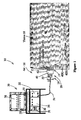
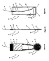
- Figure 1 schematically illustrates a system 10, having a sensor 20 for tissue characterization, in accordance with a first embodiment of the present invention.
- the sensor 20 has proximal and distal ends, 21 and 29, with respect to a tissue 18, which is the tissue to be characterized.
- the sensor 20 includes a conductive structure 42, configured to be placed proximally to an edge 13 of the tissue 18 for characterization, while in air 16, that is, without penetrating the tissue 18.
- the conductive structure 42 is operative as a resonating sensor 20.
- the conductive structure 42 defines a diameter-equivalent D - the diameter of a circle having a cross sectional area which is substantially the same as the cross-sectional area of the element 42.
- D defines a cross-sectional area on a side of the edge 13, substantially parallel with the edge 13.
- D is between about 3 mm and 25 mm. It will be appreciated that other values, which are larger or smaller, may similarly be used.
- the conductive structure 42 further defines a feature size d, which is based, for example, on a wire thickness and wire spacing, as shown hereinbelow, in conjunction with Figure 3B .
- the conductive structure 42 is associated with a circuit 40, by resistance coupling or by inductive or capacitance coupling.
- the circuit 40 communicates with an external signal-generation-control-and-analysis system 30, via a coupler 50 and a transmission line, for example, a coaxial cable 56.
- the conductive structure 42 is configured to resonate at a free-air wavelength range of between about ⁇ and about 40 ⁇ , wherein, is at least about ten times the diameter-equivalent D.
- the free-air wavelength range of between about ⁇ , and about 40 ⁇ is generally equivalent to a frequency range of between about 10 Mhz and about 5 Ghz.
- the conductive structure 42 Upon receiving a signal in the range of between about ⁇ , and about 40 ⁇ , the conductive structure 42 is configured to induce an electric field 12 and a magnetic field 14, in a near zone 17 of the tissue 18, wherein the electric field 12 penetrates the tissue 18 to a depth of d(E) and the magnetic field 14 penetrates the tissue 18 to a depth of d(B), both being of the order of magnitude of the feature size d.
- d(B) is somewhat larger than d(E), for example, by a factor of between 1.1 and 5. Alternatively, they are substantially the same. However, it will be appreciated that in some cases, d(B) may be smaller than d(E).
- the region of penetration is generally a disk 15 of a diameter, which is about the diameter-equivalent D, and a thickness of about the feature size d, which begins with the tissue edge 13.
- the tissue 18 in the disk 15 effectively functions as part of the resonator, varying its resonating response.
- the tissue 18 in the disk 15 may be characterized based on its electromagnetic properties, by its resonating response.
- the conductive structure 42 is configured as an inefficient antenna, for the free-air wavelength range of between about ⁇ , and about 40 ⁇ , so its radiation efficiency in a far zone 19 is less than 0.1%, and preferably less than 0.01%. As a result, contributions of the far zone are minimized and the tissue characterization is limited to the disk 15 of the near zone 17, very close to the edge 13.
- the external signal-generation-control-and-analysis system 30 preferably includes a signal generator 32, an analyzer 34, and a controller 36, although these may be integrated into a single unit.
- a user interface may be provided, for example, in the form of read and write drives 31, such as, a diskette, a CD, a DVD, a disk-on-key and the like, for providing predetermined operating parameters and settings, and in order to store test results.
- a display screen 38 may display the resonating response. It will be appreciated that other output means, for example, a printer or a facsimile, are also possible.
- a keyboard 35 may be used to input data such as patient details, date and time of a particular test, signal parameters, and the like.
- the controller 36 may include other input and output devices, for example, a USB port 33, and other features, as known.
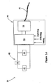
- Figures 2A and 2B illustrate schematic circuits of the sensor 20, in accordance with other embodiments of the present invention, wherein the conductive structure 42 together with an electronic support structure is operative as the resonating sensor 20.
- the sensor 20 may be represented as a circuit 40, which includes the conductive structure 42, configured to be placed proximally to the tissue 18. Additionally, the circuit 40 may include an effective component 44, having an effective resistance, an effective inductance, and an effective capacitance, and which may be connected in series with the conductive structure 42, and an effective component 46, having an effective resistance, an effective inductance, and an effective capacitance, and which may be connected in parallel with the conductive structure 42.
- either the effective component 44 or the effective components 44 and 46 may form the electronic support structure.
- the resonating sensor 20 may be effectively formed either of the conductive structure 42 and the effective component 44, or the conductive structure 42 and both the effective components 44 and 46.
- it is the overall sensor 20 which is configured to resonate at a frequency which corresponds to a free-air wavelength range of between about ⁇ and about 40 ⁇ .
- the coupler 50 preferably includes a connection structure 52, which preferably provides at least one of tuning, switching, and replacing capabilities, for example, in order to change the overall impedance of the circuit 40, or of the components 44 and 46. These capabilities may be desired to interchangeably optimize the sensor 20 for characterizing different types of tissue, for example, breast tissue, which is predominantly fat, muscle tissue, skin tissue, and bone.
- a connector 54 connects the connection structure 52 and the transmission line 56, preferably, while ensuring impedance matching and balancing.
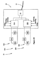
- the sensor 20 may be represented as two circuits 40A and 40B, forming two resonators, 20A and 20B, and including two conductive structures 42A and 42B, connected in parallel.
- the circuits 40A and 40B may include effective components 44A and 44B, each having an effective resistance, an effective inductance, and an effective capacitance, and which may be connected in series with the conductive structures 42A and 42B, and effective components 46A and 46B, each having an effective resistance, an effective inductance, and an effective capacitance, and which may be connected in parallel with the conductive structures 42A and 42B.
- the resonator 20A may be effectively formed of the conductive structure 42A and the effective component 44A, or the conductive structure 42A and both the effective components 44A and 46A.
- the resonating sensor 20B may be effectively formed of the conductive structure 42B and the effective component 44B, or the conductive structure 42B and both the effective components 44B and 46B
- connection structures 52A and 52B which preferably provide at least one of tuning, switching, and replacing capabilities to the circuits 42A and 42B.
- the connector 54 connects the connection structures 52A and 52B and the transmission line 56, preferably, while ensuring impedance matching and balancing.
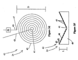
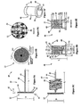
- Figures 3A - 3N schematically illustrate various geometries for the conductive structure 42 of the sensor 20 for tissue characterization, in accordance with some embodiments of the present invention
- the conductive structure 42 is formed as a flat spiral 22, of a conductive material, such as copper, gold, or another conductor, as known.
- An inner end 41 may be resistively connected to the coupler 50, via a conductive lead 43.
- a second end 47 may be free, so as to be inductively or capacitively coupled to the circuit 40 ( Figure 2A ).
- the second end 47 may be connected to the coupler 50, while the first end 41 may be free.
- the spiral 22 is associated with the diameter-equivalent D.
- the spiral 22 may be deposited on a substrate 49, to a thickness of about 2-30 microns. It will be appreciated that other dimensions may similarly be used.
- the substrate may be, for example, polycarbon, quartz, or another material as known.
- the purpose of the substrate 49 is to provide a mechanical support to the sensor 20.
- an insulation layer 48 for example, Kapton, of about 4-50 microns, may be applied over the spiral 22. It will be appreciated that other dimensions may similarly be used.
- the width d1 of the conductive material 45, and the spacing d2 are generally of the same order of magnitude, and are termed, the feature size, denoted here generally as d.
- the feature size d may influence the resolution capability of the sensor 20, especially the spatial resolution and is preferably no more than half the size of the desired resolution capability. For example, when a minimal detectable object size of about 0.25 mm is sought, a feature size which is about of about 0.1 mm, being 40% of the desired resolution capability may be used.
- the feature size d is between about 1/10 and 1/20 of the diameter-equivalent D.
- Figure 3C illustrates the spiral 22, with both ends 41 and 47 resistively coupled to the circuit 40, via conductive leads 43.
- Figure 3D illustrates a double spiral 22A, with the two inner ends 41 resistively coupled and the two outer ends 47, being free.
- Figures 3E and 3F schematically illustrate a conical helix 24, which is similarly deposited on the substrate 49.
- the substrate 49 is shaped as a funnel, to provide the conductive material 45 with the cone shape.
- the conical helix 24 is associated with the diameter-equivalent D and with a length L. Additionally, it is associated with the width d1 of the conductive material 45, and the spacing d2, as for the spiral 22.
- the conical helix 24 is shown resistively coupled. Alternatively, it may be inductively or capacitively coupled.
- FIGS 3G - 3K schematically illustrate the conductive structure 42, wherein the conductive material 45 is formed as two combs 45A and 45B, inserted into each other, as shown in Figures 3H and 3I , to form a structure 28.
- the conductive material 45 forming the structure 28 may be deposited on the insulating material 48, such as Kapton, of a thickness of about 100 microns, and covered with the insulating material 48, such as Kapton of a thickness of between about 4 and 50 microns.
- the insulating material 48 such as Kapton
- Contact points 55 provide resistive coupling to the structure 28.
- the structure 28 is placed over a hollow region 51, formed by a housing 53.
- the purpose of the hollow region 51 being to prevent a response from a distal side of the structure 28.
- an electrical insulator 51 may be used in place of the hollow region 51.
- Figures 3L and 3N further illustrate the conical helix 24, of Figure 3F , deposited on the substrate 49, shaped as the funnel, to provide the conductive material 45 with the cone shape.
- a preferably tubular wall 37 of a conductive material encloses the conical helix 24, extending beyond the conical helix on the proximal side 21 with respect to the tissue, so as to form an open cavity 39.
- the wall 37 has a length L1, which is somewhat larger than L, for example, by 10 - 100 %.
- the conical helix 24 is associated with the diameter-equivalent D and feature sizes d1 and d2, of substantially similar in value, so as to be considered d, wherein the feature size d is preferably about a tenth of the diameter-equivalent D.
- the conical helix 24 is shown resistively coupled. Alternatively, it may be inductively or capacitively coupled.
- the open cavity 39 is as taught in commonly owned US Patent 6,813,515 to Hashimshony , which describes a method and system for examining tissue by: applying an electrical pulse to the tissue to be examined via a probe formed with an open cavity such that the probe generates an electrical fringe field in the examined tissue within the open cavity and produces a reflected electrical pulse therefrom with negligible radiation penetrating into other tissues or biological bodies near the examined tissue; detecting the reflected electrical pulse; and comparing electrical characteristics of the reflected electrical pulse with respect to the applied electrical pulse to provide an indication of the dielectric properties of the examined tissue.
- the region of penetration of the tissue 18 is contained within the cavity 39.
- the tissue 18 contained within the cavity 39 effectively functions as part of the resonator, varying its resonating response.
- the tissue 18 contained within the cavity 39 may be characterized based on its electromagnetic properties, by its resonating response.
- Figure 3N illustrates a conical open cavity
- a cylindrical open cavity for example, formed by adding the conductive tubular walls 37 to the embodiment of Figures 3A and 3B , is similarly possible.
- the conductive structure 42 of any one of Figures 3A - 3N may also be associated with the circuit 40 of Figure 2A , by resistance coupling or by inductive or capacitive coupling, wherein the circuit 40 communicates with the external signal-generation-control-and-analysis system 30, via the coupler 50 and the transmission line, for example, the coaxial cable 56.
- the conductive structure 42 of any one of Figures 3A - 3N may also be associated with the circuits 40A and 40B of Figure 2B , by resistance coupling or by inductive or capacitive coupling.
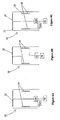
- Figures 4A - 4C schematically illustrate the sensor 20, formed as a thin, flexible construction 75, in accordance with an embodiment of the present invention.
- the senor 20 includes the spiral 22, of a thickness of about 2-30 microns, deposited on the insulating material 48, such as Kapton, of a thickness of about 100 microns, and covered with the insulating material 48, such as Kapton of a thickness of about 4-50 microns, thus being essentially self-supporting.
- the insulating material 48 such as Kapton
- the flexible construction 75 is configured to bend at a line 77, so that in operation, the spiral 22 is substantially at a right angle to the remainder of the flexible construction 75. Additionally, the flexible construction 75 is adapted for operation when inserted into a hollow housing 74, having a top cover 57 of polycarbon, wherein the spiral 22 forms a proximal cover over the top cover 57 of polycarbon, for forming contact or near contact with the edge 13 of the tissue 18 ( Figure 1 ).
- the hollow housing 74 essentially provides the effective hollow region 51, at the distal side of the sensor 22.
- housing 74 may be filled with an insulating material.
- the flexible construction 75 may be attached to the housing 74 rather than inserted therein.
- Figures 5A - 5G schematically illustrate the sensor 20 operative with a housing 70, in accordance with some embodiments of the present invention.
- the senor 20 may include the spiral 22 and a helix 26. These may be connected in series, or in parallel, as shown in Figure 2B . Additionally, either one may be resistively coupled. Alternatively, either one may be inductively or capacitively coupled, so as to have one free end.
- the housing 70 preferably includes an inner support structure 65, having a circular head 62 and a leg 64, so as a have a T-shaped cross section, and having proximal and distal ends 61 and 69, with respect to the tissue.
- the spiral 22 is preferably positioned at the head 62.
- the helix 26 may be coiled around the leg 64.
- the leg 64 may further be used to house the conductive lead 43 of the spiral 22.
- Figure 5G schematically illustrates the coupler 50 having the connection structure 52 and the connector 54, at the distal end 69 of the housing 70.
- Figures 6A - 6C schematically illustrate various manners of combining the spiral 22 and the helix 26, in accordance with some embodiments of the present invention.
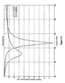
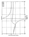
- Figures 7A and 7B schematically illustrate experimental data of the sensor for tissue characterization of the present invention.
- Figure 7A illustrates a reflection coefficient amplitude of a reflection signal.
- Figure 7B illustrates a reflection coefficient phase of a reflection signal.
- At least one of the amplitude and the phase may be used. Additionally, both may be used.
- Figures 7A and 7B illustrate the broadband nature of the resonator of the present invention. Defining a response as a change of at least 10% in the reflection coefficient amplitude of a reflection signal ( Figure 7A ), it is noted that the range of the response in Figure 7A is from about 180 to about 260 MHz. In the present example of Figure 7A , the range is 80 MHz around a resonating value of 220 MHz.
- the broadband is often defined as ⁇ f/f, or in the present example, 80/220. Expressing the broadband in percentage leads to a value of 36%, or ⁇ 18%.
- the broadband may be as much as ⁇ 50%. Alternatively, it may be at least ⁇ 25%, or at least ⁇ 15%.
- the term “substantially” refers to ⁇ 10 %.
Claims (17)
- Capteur (20) pour une caractérisation de tissu de zone proche, comprenant :un résonateur (40), configuré pour être placé à proximité d'un bord d'un tissu pour une caractérisation, sans pénétrer dans le tissu, le résonateur comprenant une structure conductrice (42) associée à une dimension D équivalente à un diamètre, dans un plan sensiblement parallèle au bord (13), etau moins un fil conducteur (43), pour réaliser une communication avec un système extérieur,le résonateur étant configuré pour résonner à une fréquence qui correspond à une plage de longueur d'onde dans l'air libre entre environ λ et environ 40λ, où est égal à au moins environ dix fois la dimension D équivalente à un diamètre,et dans lequel, lors de la réception d'un signal dans la plage entre environ λ et environ 40λ, le capteur est configuré pour induire des champs électrique et magnétique dans la zone proche dans le tissu, dans lequel, dans une zone éloignée, le capteur a un rendement de rayonnement de moins de 0,1 % pour la plage de longueur d'onde dans l'air libre entre environ λ et environ 40λ, réduisant à un minimum les contributions de la zone éloignée, la zone proche étant une région généralement similaire à un disque, délimitée par un diamètre d'environ D et par une profondeur de pénétration, etle capteur servant à une connexion à un système de commande de génération et d'analyse de signal externe (30) en communication avec le capteur, par l'intermédiaire dudit au moins un fil conducteur pour fournir le signal et caractériser ledit tissu en utilisant une réponse résonnante du résonateur;dans lequella structure conductrice (42) étant l'un d'une spirale plate, d'une spirale double, d'une hélice conique ou de deux peignes insérés l'un dans l'autre ayant une largeur de conducteur (d1) et un espacement (d2) généralement du même ordre d'amplitude qui est une taille de caractéristique (d) ;le résonateur étant un résonateur large bande, le résonateur large bande étant conçu avec une plage de réponse large bande Δf/f d'au moins ±15 %, Δf étant une plage de fréquences pour laquelle il y a un changement d'au moins 10 % de l'amplitude du coefficient de réflexion d'un signal de réflexion du résonateur, et f est une fréquence de résonance correspondante, et la profondeur de pénétration de la zone proche étant ladite taille de caractéristique (d), la profondeur de pénétration, avec ladite réduction à un minimum de la zone éloignée, garantissant qu'un tissu qui est situé dans la zone proche modifie les réponses de résonance du résonateur, et permettant que le tissu dans la zone proche soit caractérisé par ses propriétés électromagnétiques, par la réponse résonnante du résonateur large bande.
- Système pour une caractérisation de tissu, comprenant le capteur selon la revendication 1 et
un système de commande de génération et d'analyse de signal externe (30), en communication avec le capteur, par l'intermédiaire dudit au moins un fil conducteur. - Utilisation d'un capteur selon la revendication 1 ou d'un système selon la revendication 2 pour la caractérisation d'un tissu.
- Capteur selon la revendication 1 ou système selon la revendication 2 ou utilisation selon la revendication 3, dans lequel une taille de caractéristique d est entre environ 1/10 et 1/20 de la dimension D équivalente à un diamètre.
- Capteur selon la revendication 1 ou système selon la revendication 2 ou utilisation selon la revendication 3, dans lequel le résonateur comprend en outre une structure de support électronique.
- Capteur selon la revendication 1 ou système selon la revendication 2 ou utilisation selon la revendication 3, dans lequel la réponse résonnante est sélectionnée dans le groupe comprenant une amplitude de coefficient de réflexion d'un signal de réflexion et une phase de coefficient de réflexion d'un signal de réflexion.
- Capteur selon la revendication 1 ou système selon la revendication 2 ou utilisation selon la revendication 3, dans lequel le résonateur est configuré pour réagir à une plage sélectionnée dans le groupe comprenant au moins environ ±50 autour d'une valeur de résonance, au moins environ ±25 % autour d'une valeur de résonance,
- Capteur selon la revendication 1 ou système selon la revendication 2 ou utilisation selon la revendication 3, dans lequel le capteur comprend en outre un connecteur pour une ligne de transmission, le connecteur réalisant une adaptation d'impédance significative entre le capteur et la ligne de transmission.
- Capteur selon la revendication 8 ou système selon la revendication 8 ou utilisation selon la revendication 8, dans lequel le capteur comprend en outre une structure de connexion, associée au connecteur, pour fournir une capacité sélectionnée dans le groupe comprenant une capacité d'accord, une capacité de commutation et une capacité de remplacement, à des composants du connecteur, pour optimiser de façon interchangeable le capteur pour différentes applications.
- Capteur selon la revendication 1 ou système selon la revendication 2 ou utilisation selon la revendication 3, dans lequel le capteur est formé en tant que construction, sélectionnée dans le groupe comprenant :une mince construction souple,une mince construction souple, adaptée pour fonctionner lorsqu'elle est attachée à un logement creux,une mince construction souple, adaptée pour fonctionner lorsqu'elle est attachée à un logement, rempli d'un matériau électriquement isolant,une mince construction souple, adaptée pour fonctionner lorsqu'elle est insérée dans un logement creux,une mince construction souple, adaptée pour fonctionner lorsqu'elle est insérée dans un logement, rempli d'un matériau électriquement isolant.
- Capteur selon la revendication 1 ou système selon la revendication 2 ou utilisation selon la revendication 3, dans lequel la structure conductrice est la spirale plate ou la spirale double, le capteur est formé en tant que mince construction souple, adaptée pour fonctionner d'une manière sélectionnée dans le groupe :lorsqu'elle est attachée à un logement, etlorsqu'elle est insérée dans un logement,dans lequel la structure conductrice est coudée pour former un dessus proximal pour le logement.
- Capteur selon la revendication 1 ou système selon la revendication 2 ou utilisation selon la revendication 3, dans lequel la structure conductrice est formée en tant qu'hélice conique et dans lequel le capteur est déposé sur un substrat en forme d'entonnoir.
- Capteur ou système ou utilisation selon la revendication 12, dans lequel le capteur comprend en outre une paroi tubulaire en un matériau conducteur, s'étendant de manière proximale vers le tissu, pour former une cavité ouverte, sélectionnée dans le groupe comprenant :une cavité ouverte conique, etune cavité ouverte cylindrique.
- Capteur ou système ou utilisation selon la revendication 13, dans lequel la zone proche est contenue dans la cavité ouverte.
- Capteur selon la revendication 1 ou système selon la revendication 2 ou utilisation selon la revendication 3, dans lequel la structure conductrice est sélectionnée dans le groupe comprenant :une structure conductrice déposée sur un substrat autoporteur,une structure conductrice, déposée sur un substrat mince et placée sur un logement qui forme une région creuse, etune structure conductrice, déposée sur un substrat mince et placée sur un logement, qui est constitué d'un isolateur électrique.
- Capteur selon la revendication 1 ou système selon la revendication 2 ou utilisation selon la revendication 3, dans lequel la structure conductrice est constituée de deux parties, une spirale sensiblement plate et une hélice, et en outre dans lequel les deux parties sont connectées d'une manière sélectionnée dans le groupe comprenant parallèle et série.
- Capteur selon la revendication 1 ou système selon la revendication 2 ou utilisation selon la revendication 3, dans lequel D est entre environ 3 et environ 25 mm.
Applications Claiming Priority (2)
| Application Number | Priority Date | Filing Date | Title |
|---|---|---|---|
| US66584205P | 2005-03-29 | 2005-03-29 | |
| PCT/IL2006/000392 WO2006103665A2 (fr) | 2005-03-29 | 2006-03-29 | Capteurs electromagnetiques pour la caracterisation de tissu |
Publications (3)
| Publication Number | Publication Date |
|---|---|
| EP1890596A2 EP1890596A2 (fr) | 2008-02-27 |
| EP1890596A4 EP1890596A4 (fr) | 2009-07-08 |
| EP1890596B1 true EP1890596B1 (fr) | 2013-10-02 |
Family
ID=37053782
Family Applications (1)
| Application Number | Title | Priority Date | Filing Date |
|---|---|---|---|
| EP06728196.4A Active EP1890596B1 (fr) | 2005-03-29 | 2006-03-29 | Capteurs electromagnetiques pour la caracterisation de tissu |
Country Status (7)
| Country | Link |
|---|---|
| US (1) | US7899515B2 (fr) |
| EP (1) | EP1890596B1 (fr) |
| JP (1) | JP5308812B2 (fr) |
| CN (2) | CN101991415B (fr) |
| CA (1) | CA2603025C (fr) |
| ES (1) | ES2434851T3 (fr) |
| WO (1) | WO2006103665A2 (fr) |
Families Citing this family (34)
| Publication number | Priority date | Publication date | Assignee | Title |
|---|---|---|---|---|
| US7505811B2 (en) | 2001-11-19 | 2009-03-17 | Dune Medical Devices Ltd. | Method and apparatus for examining tissue for predefined target cells, particularly cancerous cells, and a probe useful in such method and apparatus |
| US7720532B2 (en) | 2004-03-23 | 2010-05-18 | Dune Medical Ltd. | Clean margin assessment tool |
| US8721565B2 (en) * | 2005-08-04 | 2014-05-13 | Dune Medical Devices Ltd. | Device for forming an effective sensor-to-tissue contact |
| US8019411B2 (en) * | 2002-01-04 | 2011-09-13 | Dune Medical Devices Ltd. | Probes, systems, and methods for examining tissue according to the dielectric properties thereof |
| US8032211B2 (en) * | 2002-01-04 | 2011-10-04 | Dune Medical Devices Ltd. | Probes, systems, and methods for examining tissue according to the dielectric properties thereof |
| US8116845B2 (en) | 2005-08-04 | 2012-02-14 | Dune Medical Devices Ltd. | Tissue-characterization probe with effective sensor-to-tissue contact |
| US20080154090A1 (en) * | 2005-01-04 | 2008-06-26 | Dune Medical Devices Ltd. | Endoscopic System for In-Vivo Procedures |
| US20080287750A1 (en) * | 2002-01-04 | 2008-11-20 | Dune Medical Devices Ltd. | Ergonomic probes |
| US7904145B2 (en) | 2004-03-23 | 2011-03-08 | Dune Medical Devices Ltd. | Clean margin assessment tool |
| US9750425B2 (en) | 2004-03-23 | 2017-09-05 | Dune Medical Devices Ltd. | Graphical user interfaces (GUI), methods and apparatus for data presentation |
| US8588887B2 (en) | 2006-09-06 | 2013-11-19 | Innurvation, Inc. | Ingestible low power sensor device and system for communicating with same |
| WO2008030482A2 (fr) | 2006-09-06 | 2008-03-13 | Innurvation Inc | Système et procédé pour un échange d'informations acoustiques mettant en jeu une capsule à faible puissance pouvant être ingérée |
| US8147423B2 (en) | 2007-03-01 | 2012-04-03 | Dune Medical Devices, Ltd. | Tissue-characterization system and method |
| US9999353B2 (en) | 2007-07-16 | 2018-06-19 | Dune Medical Devices Ltd. | Medical device and method for use in tissue characterization and treatment |
| US9757098B2 (en) | 2007-07-16 | 2017-09-12 | Dune Medical Devices Ltd. | Medical device and method for use in tissue characterization and treatment |
| US9901362B2 (en) | 2007-07-16 | 2018-02-27 | Dune Medical Devices Ltd. | Medical device and method for use in tissue characterization and treatment |
| EP2178443B1 (fr) | 2007-07-16 | 2015-07-08 | Dune Medical Devices Ltd. | Dispositif médical pour une utilisation dans la caractérisation et le traitement des tissus |
| CN101377983B (zh) * | 2007-08-29 | 2012-03-14 | 博西华电器(江苏)有限公司 | 家用电器操作装置和指示单元操作方法 |
| US9197470B2 (en) | 2007-10-05 | 2015-11-24 | Innurvation, Inc. | Data transmission via multi-path channels using orthogonal multi-frequency signals with differential phase shift keying modulation |
| DE102008064405A1 (de) | 2008-06-02 | 2009-12-10 | Rohde & Schwarz Gmbh & Co. Kg | Messvorrichtung und Verfahren zur Bestimmung von Gewebeparametern |
| WO2010005571A2 (fr) | 2008-07-09 | 2010-01-14 | Innurvation, Inc. | Affichage de données image d’une capsule de numériseur |
| CN102573622B (zh) * | 2009-08-03 | 2016-01-27 | 沙丘医疗设备有限公司 | 用于对受试者进行测量的电磁传感器 |
| JP5889186B2 (ja) * | 2009-08-03 | 2016-03-22 | デューン・メディカル・デバイシズ・リミテッド | サージカルツール |
| US9192353B2 (en) | 2009-10-27 | 2015-11-24 | Innurvation, Inc. | Data transmission via wide band acoustic channels |
| US8647259B2 (en) | 2010-03-26 | 2014-02-11 | Innurvation, Inc. | Ultrasound scanning capsule endoscope (USCE) |
| EP2800510B1 (fr) | 2012-01-05 | 2018-09-19 | Sensible Medical Innovations Ltd. | Sondes électromagnétiques (em), leurs procédés d'utilisation, et systèmes les utilisant |
| JP6470173B2 (ja) | 2012-07-12 | 2019-02-13 | デューン メディカル デヴァイシズ リミテッドDune Medical Devices Ltd. | 組織性状診断及び治療で用いる医療装置 |
| TWI481385B (zh) * | 2012-10-02 | 2015-04-21 | Univ Lunghwa Sci & Technology | Non - invasive blood glucose measurement circuit module |
| US9402582B1 (en) | 2014-04-21 | 2016-08-02 | Verily Life Sciences Llc | Smart surgical glove |
| FI127021B (fi) * | 2014-06-02 | 2017-09-29 | Senfit Oy | Anturi, mittalaite ja mittausmenetelmä |
| CN105167223B (zh) * | 2014-10-22 | 2016-11-30 | 北京至感传感器技术研究院有限公司 | 用于检测乳房生理变化的胸罩 |
| CN105266213A (zh) * | 2014-11-10 | 2016-01-27 | 北京至感传感器技术研究院有限公司 | 用于检测乳房生理变化的胸罩 |
| CN105476081A (zh) * | 2015-02-12 | 2016-04-13 | 北京至感传感器技术研究院有限公司 | 胸罩组件 |
| US11293963B2 (en) * | 2017-11-28 | 2022-04-05 | Nxp B.V. | Device for electromagnetic structural characterization |
Family Cites Families (126)
| Publication number | Priority date | Publication date | Assignee | Title |
|---|---|---|---|---|
| US3830224A (en) | 1972-12-19 | 1974-08-20 | Vanzetti Infrared Computer Sys | Means for detecting changes in the temperature of the skin |
| IL53286A (en) | 1977-11-02 | 1980-01-31 | Yeda Res & Dev | Apparatus and method for detection of tumors in tissue |
| US4458694A (en) | 1977-11-02 | 1984-07-10 | Yeda Research & Development Co., Ltd. | Apparatus and method for detection of tumors in tissue |
| USRE32000E (en) | 1978-05-22 | 1985-10-08 | B.C.S.I. Laboratories, Inc. | Device for use in early detection of breast cancer |
| US4344440A (en) | 1980-04-01 | 1982-08-17 | Trygve Aaby | Microprobe for monitoring biophysical phenomena associated with cardiac and neural activity |
| JPS5772627A (en) | 1980-10-21 | 1982-05-07 | Tokyo Shibaura Electric Co | Apparatus for detecting abnormal cell |
| CA1196691A (fr) | 1982-01-12 | 1985-11-12 | Bradley Fry | Systeme et methodes de reconstruction pour imagerie a impedance |
| US4617939A (en) | 1982-04-30 | 1986-10-21 | The University Of Sheffield | Tomography |
| JPS59148854A (ja) | 1983-02-14 | 1984-08-25 | Hitachi Ltd | 核磁気共鳴を用いた検査装置 |
| JPS6018768A (ja) * | 1983-07-12 | 1985-01-30 | Katsuo Ebara | 非接触式電導率、誘電率同時測定センサ |
| US4689567A (en) | 1984-06-01 | 1987-08-25 | Advanced Nmr Systems, Inc. | NMR Fourier imaging from multiple echoes |
| US4682594A (en) | 1985-03-11 | 1987-07-28 | Mcm Laboratories, Inc. | Probe-and-fire lasers |
| JPS62247232A (ja) | 1986-04-21 | 1987-10-28 | Agency Of Ind Science & Technol | 蛍光測定装置 |
| JP2590317B2 (ja) | 1986-05-21 | 1997-03-12 | オリンパス光学工業株式会社 | 内視鏡 |
| US4841249A (en) * | 1986-10-28 | 1989-06-20 | Siemens Aktiengesellschaft | Truncated cone shaped surface resonator for nuclear magnetic resonance tomography |
| JPS63118648A (ja) * | 1986-11-07 | 1988-05-23 | Jeol Ltd | ル−プギヤツプ共振器を備えた電子スピン共鳴装置 |
| US4785806A (en) | 1987-01-08 | 1988-11-22 | Yale University | Laser ablation process and apparatus |
| US4751464A (en) | 1987-05-04 | 1988-06-14 | Advanced Nmr Systems, Inc. | Cavity resonator with improved magnetic field uniformity for high frequency operation and reduced dielectric heating in NMR imaging devices |
| US5277730A (en) | 1987-12-16 | 1994-01-11 | At&T Bell Laboratories | Methods of recoating spliced lengths of optical fibers |
| JP2740528B2 (ja) * | 1988-10-20 | 1998-04-15 | 学校法人東海大学 | 物性測定装置 |
| SE8900612D0 (sv) | 1989-02-22 | 1989-02-22 | Jonas Johansson | Vaevnadskarakterisering utnyttjande ett blodfritt fluorescenskriterium |
| IL91193A (en) | 1989-08-02 | 1996-01-19 | Yeda Res & Dev | Tumor detection system |
| US5922304A (en) | 1989-12-22 | 1999-07-13 | Imarx Pharmaceutical Corp. | Gaseous precursor filled microspheres as magnetic resonance imaging contrast agents |
| US6671540B1 (en) | 1990-08-10 | 2003-12-30 | Daryl W. Hochman | Methods and systems for detecting abnormal tissue using spectroscopic techniques |
| DE69133603D1 (de) | 1990-10-19 | 2008-10-02 | Univ St Louis | System zur Lokalisierung einer chirurgischen Sonde relativ zum Kopf |
| JP2946843B2 (ja) * | 1991-07-08 | 1999-09-06 | 東陶機器株式会社 | 果実等の熟成度の判定方法及び熟成度判定センサ |
| US5482041A (en) | 1992-06-05 | 1996-01-09 | Wilk; Peter J. | Medical investigation system and related method |
| US5442290A (en) | 1992-08-04 | 1995-08-15 | The Regents Of The University Of California | MRI gradient drive current control using all digital controller |
| WO1994004938A1 (fr) | 1992-08-14 | 1994-03-03 | British Telecommunications Public Limited Company | Dispositif de localisation d'une position |
| US5227730A (en) | 1992-09-14 | 1993-07-13 | Kdc Technology Corp. | Microwave needle dielectric sensors |
| US5334941A (en) | 1992-09-14 | 1994-08-02 | Kdc Technology Corp. | Microwave reflection resonator sensors |
| US5381795A (en) | 1993-11-19 | 1995-01-17 | Advanced Technology Laboratories, Inc. | Intraoperative ultrasound probe |
| US5678565A (en) | 1992-12-21 | 1997-10-21 | Artann Corporation | Ultrasonic elasticity imaging method and device |
| AU694135B2 (en) | 1993-07-30 | 1998-07-16 | Imcor Pharmaceutical Company | Stabilized microbubble compositions for ultrasound |
| JPH0792115A (ja) * | 1993-09-24 | 1995-04-07 | Junkosha Co Ltd | 電子スピン共鳴装置 |
| ZA948393B (en) | 1993-11-01 | 1995-06-26 | Polartechnics Ltd | Method and apparatus for tissue type recognition |
| US6500112B1 (en) | 1994-03-30 | 2002-12-31 | Brava, Llc | Vacuum dome with supporting rim and rim cushion |
| EP0694282B1 (fr) | 1994-07-01 | 2004-01-02 | Interstitial, LLC | Détection et visualisation du cancer du sein par ondes électromagnétiques millimétriques |
| US5829437A (en) | 1994-07-01 | 1998-11-03 | Interstitial, Inc. | Microwave method and system to detect and locate cancers in heterogenous tissues |
| US5704355A (en) | 1994-07-01 | 1998-01-06 | Bridges; Jack E. | Non-invasive system for breast cancer detection |
| GB9418183D0 (en) | 1994-09-09 | 1994-10-26 | Chan Tsing Y A | Non-destructive method for determination of polar molecules on rigid and semi-rigid substrates |
| US5758646A (en) | 1994-09-12 | 1998-06-02 | U.S. Philips Corporation | Magnetic resonance imaging method with pulse sequence optimization and device for such method |
| US5810742A (en) | 1994-10-24 | 1998-09-22 | Transcan Research & Development Co., Ltd. | Tissue characterization based on impedance images and on impedance measurements |
| WO1996015550A1 (fr) | 1994-11-10 | 1996-05-23 | Lawrence Semiconductor Research Laboratory, Inc. | Compositions silicium-germanium-carbone et processus associes |
| US5630426A (en) | 1995-03-03 | 1997-05-20 | Neovision Corporation | Apparatus and method for characterization and treatment of tumors |
| US6258576B1 (en) | 1996-06-19 | 2001-07-10 | Board Of Regents, The University Of Texas System | Diagnostic method and apparatus for cervical squamous intraepithelial lesions in vitro and in vivo using fluorescence spectroscopy |
| US5558092A (en) | 1995-06-06 | 1996-09-24 | Imarx Pharmaceutical Corp. | Methods and apparatus for performing diagnostic and therapeutic ultrasound simultaneously |
| US5964740A (en) | 1996-07-09 | 1999-10-12 | Asahi Kogaku Kogyo Kabushiki Kaisha | Treatment accessory for an endoscope |
| DE19520749C1 (de) | 1995-06-07 | 1996-08-08 | Siemens Ag | Therapiegerät mit einer Quelle akustischer Wellen |
| US5572132A (en) | 1995-08-15 | 1996-11-05 | Pulyer; Yuly M. | MRI probe for external imaging |
| US5836311A (en) | 1995-09-20 | 1998-11-17 | Medtronic, Inc. | Method and apparatus for temporarily immobilizing a local area of tissue |
| US5769784A (en) | 1995-11-27 | 1998-06-23 | Hill-Rom, Inc. | Skin perfusion evaluation apparatus and method |
| US5729475A (en) | 1995-12-27 | 1998-03-17 | Romanik, Jr.; Carl J. | Optical system for accurate monitoring of the position and orientation of an object |
| JP3369829B2 (ja) * | 1996-01-17 | 2003-01-20 | 花王株式会社 | 水分測定装置 |
| EP0791823A3 (fr) | 1996-02-20 | 1997-12-10 | Hauni Maschinenbau Aktiengesellschaft | Méthode et appareil pour mesurer au moins une propriété d'un matériau |
| US5727569A (en) | 1996-02-20 | 1998-03-17 | Cardiothoracic Systems, Inc. | Surgical devices for imposing a negative pressure to fix the position of cardiac tissue during surgery |
| DE19734978B4 (de) | 1997-02-12 | 2013-10-17 | Hauni Maschinenbau Ag | Verfahren und Anordnung zum Erfassen mindestens einer Eigenschaft eines Stoffes |
| US6004263A (en) | 1996-03-13 | 1999-12-21 | Hihon Kohden Corporation | Endoscope with detachable operation unit and insertion unit |
| US5735278A (en) | 1996-03-15 | 1998-04-07 | National Research Council Of Canada | Surgical procedure with magnetic resonance imaging |
| US6173604B1 (en) | 1996-09-20 | 2001-01-16 | The Regents Of The University Of California | Scanning evanescent electro-magnetic microscope |
| US5821410A (en) | 1996-09-20 | 1998-10-13 | Regents Of The University Of California | Scanning tip microwave near field microscope |
| US6058323A (en) | 1996-11-05 | 2000-05-02 | Lemelson; Jerome | System and method for treating select tissue in a living being |
| US6109270A (en) | 1997-02-04 | 2000-08-29 | The United States Of America As Represented By The Administrator Of The National Aeronautics And Space Administration | Multimodality instrument for tissue characterization |
| US6086534A (en) | 1997-03-07 | 2000-07-11 | Cardiogenesis Corporation | Apparatus and method of myocardial revascularization using ultrasonic pulse-echo distance ranging |
| US6026323A (en) | 1997-03-20 | 2000-02-15 | Polartechnics Limited | Tissue diagnostic system |
| US5900618A (en) | 1997-08-26 | 1999-05-04 | University Of Maryland | Near-field scanning microwave microscope having a transmission line with an open end |
| US6135968A (en) | 1997-09-10 | 2000-10-24 | Scantek Medical, Inc. | Differential temperature measuring device and method |
| US6071239A (en) | 1997-10-27 | 2000-06-06 | Cribbs; Robert W. | Method and apparatus for lipolytic therapy using ultrasound energy |
| US6375634B1 (en) | 1997-11-19 | 2002-04-23 | Oncology Innovations, Inc. | Apparatus and method to encapsulate, kill and remove malignancies, including selectively increasing absorption of x-rays and increasing free-radical damage to residual tumors targeted by ionizing and non-ionizing radiation therapy |
| US20010045832A1 (en) | 1997-11-26 | 2001-11-29 | Kenneth W. Belt | Peripheral vascular array |
| US6055451A (en) | 1997-12-12 | 2000-04-25 | Spectrx, Inc. | Apparatus and method for determining tissue characteristics |
| US6081738A (en) | 1998-01-15 | 2000-06-27 | Lumend, Inc. | Method and apparatus for the guided bypass of coronary occlusions |
| US6331166B1 (en) | 1998-03-03 | 2001-12-18 | Senorx, Inc. | Breast biopsy system and method |
| JPH11304764A (ja) * | 1998-04-27 | 1999-11-05 | Omron Corp | 水分センサ |
| CA2331644A1 (fr) | 1998-05-12 | 1999-11-18 | Neil J. Goldfine | Procede d'utilisation de signaux dielecytrometriques utilisant des grilles d'estimation |
| US6233479B1 (en) | 1998-09-15 | 2001-05-15 | The Regents Of The University Of California | Microwave hematoma detector |
| JP3794848B2 (ja) * | 1998-12-28 | 2006-07-12 | 三井化学株式会社 | ミリ波帯での誘電率測定方法及び測定装置 |
| US6090041A (en) | 1999-02-16 | 2000-07-18 | Regents Of The University Of California | vacuum actuated surgical retractor and methods |
| US6397095B1 (en) | 1999-03-01 | 2002-05-28 | The Trustees Of The University Of Pennsylvania | Magnetic resonance—electrical impedance tomography |
| US6546787B1 (en) | 1999-03-25 | 2003-04-15 | Regents Of The University Of Minnesota | Means and method for modeling and treating specific tissue structures |
| DE60031661D1 (de) | 1999-04-20 | 2006-12-14 | Nova Technology Corp | Verfahren und vorrichtung zur messung des wasseranteils in einem substrat |
| US6167297A (en) | 1999-05-05 | 2000-12-26 | Benaron; David A. | Detecting, localizing, and targeting internal sites in vivo using optical contrast agents |
| DE19925468A1 (de) | 1999-06-03 | 2000-12-07 | Hauni Maschinenbau Ag | Streufeldsonde |
| US6287302B1 (en) | 1999-06-14 | 2001-09-11 | Fidus Medical Technology Corporation | End-firing microwave ablation instrument with horn reflection device |
| US6695782B2 (en) | 1999-10-05 | 2004-02-24 | Omnisonics Medical Technologies, Inc. | Ultrasonic probe device with rapid attachment and detachment means |
| GB2357149A (en) | 1999-12-08 | 2001-06-13 | Topspin Medical | MRI using non-homogeneous static field |
| US20020120265A1 (en) | 1999-12-23 | 2002-08-29 | Mayo Foundation For Medical Education And Research | Symmetric conization electrocautery device |
| US6530944B2 (en) | 2000-02-08 | 2003-03-11 | Rice University | Optically-active nanoparticles for use in therapeutic and diagnostic methods |
| JP5090600B2 (ja) | 2000-02-18 | 2012-12-05 | トーマス ジェイ. フォガーティー, | 正確に組織に印を付けるための改善されたデバイス |
| US6722371B1 (en) | 2000-02-18 | 2004-04-20 | Thomas J. Fogarty | Device for accurately marking tissue |
| US6564806B1 (en) | 2000-02-18 | 2003-05-20 | Thomas J. Fogarty | Device for accurately marking tissue |
| US6728565B2 (en) | 2000-02-25 | 2004-04-27 | Scimed Life Systems, Inc. | Diagnostic catheter using a vacuum for tissue positioning |
| US7499745B2 (en) | 2000-02-28 | 2009-03-03 | Barbara Ann Karmanos Cancer Institute | Multidimensional bioelectrical tissue analyzer |
| GB2360132B (en) * | 2000-03-06 | 2002-04-24 | Marconi Caswell Ltd | Structure with switchable magnetic properties |
| US6377841B1 (en) | 2000-03-31 | 2002-04-23 | Vanderbilt University | Tumor demarcation using optical spectroscopy |
| US6766185B2 (en) | 2000-05-22 | 2004-07-20 | The Board Of Trustees Of The Leland Stanford Junior University | Transmission line techniques for MRI catheter coil miniaturization and tuning |
| WO2002032335A1 (fr) | 2000-07-25 | 2002-04-25 | Rita Medical Systems Inc. | Appareil pour detecter et traiter des tumeurs par une mesure d'impedance localisee |
| JP2002071596A (ja) * | 2000-08-25 | 2002-03-08 | Yamagata Public Corp For The Development Of Industry | 電子スピン共鳴の計測方法および計測装置 |
| ATE408809T1 (de) | 2000-08-31 | 2008-10-15 | Toudai Tlo Ltd | Optischer tastsensor |
| US6597185B1 (en) | 2000-09-20 | 2003-07-22 | Neocera, Inc. | Apparatus for localized measurements of complex permittivity of a material |
| US6544185B2 (en) | 2000-10-23 | 2003-04-08 | Valentino Montegrande | Ultrasound imaging marker and method of use |
| US6871086B2 (en) | 2001-02-15 | 2005-03-22 | Robin Medical Inc. | Endoscopic examining apparatus particularly useful in MRI, a probe useful in such apparatus, and a method of making such probe |
| WO2002069791A1 (fr) | 2001-03-06 | 2002-09-12 | Pendragon Medical Ltd. | Procede et dispositif destines a determiner la concentration d'une substance dans un liquide corporel |
| US6556013B2 (en) * | 2001-03-09 | 2003-04-29 | Bruker Biospin Corp. | Planar NMR coils with localized field-generating and capacitive elements |
| WO2003009752A2 (fr) * | 2001-07-26 | 2003-02-06 | Chad Edward Bouton | Capteurs electromagnetiques destines a des applications sur des tissus biologiques et techniques d'utilisation |
| US6592520B1 (en) | 2001-07-31 | 2003-07-15 | Koninklijke Philips Electronics N.V. | Intravascular ultrasound imaging apparatus and method |
| US20030045798A1 (en) | 2001-09-04 | 2003-03-06 | Richard Hular | Multisensor probe for tissue identification |
| US7505811B2 (en) | 2001-11-19 | 2009-03-17 | Dune Medical Devices Ltd. | Method and apparatus for examining tissue for predefined target cells, particularly cancerous cells, and a probe useful in such method and apparatus |
| US20070255169A1 (en) | 2001-11-19 | 2007-11-01 | Dune Medical Devices Ltd. | Clean margin assessment tool |
| US7809425B2 (en) | 2003-07-24 | 2010-10-05 | Dune Medical Devices Ltd. | Method and apparatus for examining a substance, particularly tissue, to characterize its type |
| US8116845B2 (en) | 2005-08-04 | 2012-02-14 | Dune Medical Devices Ltd. | Tissue-characterization probe with effective sensor-to-tissue contact |
| US20080154090A1 (en) | 2005-01-04 | 2008-06-26 | Dune Medical Devices Ltd. | Endoscopic System for In-Vivo Procedures |
| US8721565B2 (en) | 2005-08-04 | 2014-05-13 | Dune Medical Devices Ltd. | Device for forming an effective sensor-to-tissue contact |
| US8032211B2 (en) | 2002-01-04 | 2011-10-04 | Dune Medical Devices Ltd. | Probes, systems, and methods for examining tissue according to the dielectric properties thereof |
| US20080287750A1 (en) | 2002-01-04 | 2008-11-20 | Dune Medical Devices Ltd. | Ergonomic probes |
| US7720532B2 (en) | 2004-03-23 | 2010-05-18 | Dune Medical Ltd. | Clean margin assessment tool |
| US8019411B2 (en) | 2002-01-04 | 2011-09-13 | Dune Medical Devices Ltd. | Probes, systems, and methods for examining tissue according to the dielectric properties thereof |
| US6813515B2 (en) | 2002-01-04 | 2004-11-02 | Dune Medical Devices Ltd. | Method and system for examining tissue according to the dielectric properties thereof |
| US20030199753A1 (en) | 2002-04-23 | 2003-10-23 | Ethicon Endo-Surgery | MRI compatible biopsy device with detachable probe |
| US6846290B2 (en) | 2002-05-14 | 2005-01-25 | Riverside Research Institute | Ultrasound method and system |
| US6840948B2 (en) | 2002-06-06 | 2005-01-11 | Ethicon-Endo Surgery, Inc. | Device for removal of tissue lesions |
| US6936003B2 (en) | 2002-10-29 | 2005-08-30 | Given Imaging Ltd | In-vivo extendable element device and system, and method of use |
| US7725151B2 (en) * | 2003-06-02 | 2010-05-25 | Van Der Weide Daniel Warren | Apparatus and method for near-field imaging of tissue |
| CN100473336C (zh) | 2003-07-24 | 2009-04-01 | 沙丘医疗设备有限公司 | 用于检查特别是组织的物质以表征其类型的方法和设备 |
| JP4461763B2 (ja) | 2003-10-02 | 2010-05-12 | オムロンヘルスケア株式会社 | 内臓脂肪算出装置 |
| US7904145B2 (en) | 2004-03-23 | 2011-03-08 | Dune Medical Devices Ltd. | Clean margin assessment tool |
-
2006
- 2006-03-29 CN CN2010105281130A patent/CN101991415B/zh active Active
- 2006-03-29 WO PCT/IL2006/000392 patent/WO2006103665A2/fr active Search and Examination
- 2006-03-29 EP EP06728196.4A patent/EP1890596B1/fr active Active
- 2006-03-29 JP JP2008503679A patent/JP5308812B2/ja active Active
- 2006-03-29 ES ES06728196T patent/ES2434851T3/es active Active
- 2006-03-29 US US11/887,571 patent/US7899515B2/en active Active
- 2006-03-29 CN CN2006800190264A patent/CN101184435B/zh active Active
- 2006-03-29 CA CA2603025A patent/CA2603025C/fr active Active
Also Published As
| Publication number | Publication date |
|---|---|
| CN101184435B (zh) | 2010-12-15 |
| ES2434851T3 (es) | 2013-12-17 |
| JP5308812B2 (ja) | 2013-10-09 |
| EP1890596A4 (fr) | 2009-07-08 |
| US7899515B2 (en) | 2011-03-01 |
| CN101991415B (zh) | 2013-04-10 |
| CN101991415A (zh) | 2011-03-30 |
| WO2006103665A9 (fr) | 2006-12-14 |
| CN101184435A (zh) | 2008-05-21 |
| JP2009501898A (ja) | 2009-01-22 |
| WO2006103665A2 (fr) | 2006-10-05 |
| EP1890596A2 (fr) | 2008-02-27 |
| WO2006103665A3 (fr) | 2007-07-05 |
| CA2603025A1 (fr) | 2006-10-05 |
| US20090062637A1 (en) | 2009-03-05 |
| CA2603025C (fr) | 2014-05-20 |
Similar Documents
| Publication | Publication Date | Title |
|---|---|---|
| EP1890596B1 (fr) | Capteurs electromagnetiques pour la caracterisation de tissu | |
| Govind et al. | Metamaterial-inspired microwave microfluidic sensor for glucose monitoring in aqueous solutions | |
| US8019411B2 (en) | Probes, systems, and methods for examining tissue according to the dielectric properties thereof | |
| US8032211B2 (en) | Probes, systems, and methods for examining tissue according to the dielectric properties thereof | |
| US20050107718A1 (en) | Method and system for examining tissue according to the dielectric properties thereof | |
| JP5889186B2 (ja) | サージカルツール | |
| KR101184420B1 (ko) | 비?침습 센서를 이용한 혈당 측정 장치 및 방법 | |
| US20050021019A1 (en) | Method and apparatus for examining a substance, particularly tissue, to characterize its type | |
| JP5699147B2 (ja) | 被験者の測定に使用するための電磁センサ | |
| Caratelli et al. | Accurate time-domain modeling of reconfigurable antenna sensors for non-invasive melanoma skin cancer detection | |
| US20150216442A1 (en) | Multilayer coaxial probe for impedance spatial contrast measurement | |
| CZ20032650A3 (cs) | Způsob a zařízení k určení koncentrace látky v tělní tekutině | |
| WO2001076475A2 (fr) | Detecteur de tumeur de la prostate chez l'homme | |
| JP7447990B2 (ja) | 誘電分光測定装置および方法 | |
| EP2665998A2 (fr) | Système de petite antenne à pôle en spirale | |
| Yi et al. | Noninvasive glucose sensors using defective-ground-structure coplanar waveguide | |
| CN113993454A (zh) | 用于生物检测的共振器组装体及利用电磁波的生物传感器 | |
| JP2001509599A (ja) | 電気、磁気およびそれ等から導かれる材料特性を測定および/または表示する装置 | |
| JP5688036B2 (ja) | 誘電率および/または透磁率を測定する方法および装置 | |
| Karatepe et al. | A monopole microwave-assisted electrochemical sensor for the detection of liquid chemicals. | |
| WO2000004375A1 (fr) | Instrument de mesure par micro-ondes et methode afferente | |
| Tian et al. | Enhanced sensitivity of wired and wireless measurement for liquid concentration based on a modified cylindrical cavity | |
| Kleismit et al. | Local complex permittivity measurements of porcine skin tissue in the frequency range from 1 GHz to 15 GHz by evanescent microscopy | |
| Bondarenko et al. | Study into the resonator structures with microprobe sensing elements | |
| Ehtaiba | Elliptic Aperture Coaxial Sensor |
Legal Events
| Date | Code | Title | Description |
|---|---|---|---|
| PUAI | Public reference made under article 153(3) epc to a published international application that has entered the european phase |
Free format text: ORIGINAL CODE: 0009012 |
|
| 17P | Request for examination filed |
Effective date: 20071017 |
|
| AK | Designated contracting states |
Kind code of ref document: A2 Designated state(s): AT BE BG CH CY CZ DE DK EE ES FI FR GB GR HU IE IS IT LI LT LU LV MC NL PL PT RO SE SI SK TR |
|
| DAX | Request for extension of the european patent (deleted) | ||
| A4 | Supplementary search report drawn up and despatched |
Effective date: 20090605 |
|
| 17Q | First examination report despatched |
Effective date: 20091007 |
|
| GRAP | Despatch of communication of intention to grant a patent |
Free format text: ORIGINAL CODE: EPIDOSNIGR1 |
|
| INTG | Intention to grant announced |
Effective date: 20130524 |
|
| GRAS | Grant fee paid |
Free format text: ORIGINAL CODE: EPIDOSNIGR3 |
|
| GRAA | (expected) grant |
Free format text: ORIGINAL CODE: 0009210 |
|
| AK | Designated contracting states |
Kind code of ref document: B1 Designated state(s): AT BE BG CH CY CZ DE DK EE ES FI FR GB GR HU IE IS IT LI LT LU LV MC NL PL PT RO SE SI SK TR |
|
| REG | Reference to a national code |
Ref country code: GB Ref legal event code: FG4D |
|
| REG | Reference to a national code |
Ref country code: CH Ref legal event code: EP Ref country code: AT Ref legal event code: REF Ref document number: 634209 Country of ref document: AT Kind code of ref document: T Effective date: 20131015 |
|
| REG | Reference to a national code |
Ref country code: IE Ref legal event code: FG4D |
|
| REG | Reference to a national code |
Ref country code: DE Ref legal event code: R096 Ref document number: 602006038662 Country of ref document: DE Effective date: 20131128 |
|
| REG | Reference to a national code |
Ref country code: NL Ref legal event code: T3 |
|
| REG | Reference to a national code |
Ref country code: ES Ref legal event code: FG2A Ref document number: 2434851 Country of ref document: ES Kind code of ref document: T3 Effective date: 20131217 |
|
| REG | Reference to a national code |
Ref country code: AT Ref legal event code: MK05 Ref document number: 634209 Country of ref document: AT Kind code of ref document: T Effective date: 20131002 |
|
| PG25 | Lapsed in a contracting state [announced via postgrant information from national office to epo] |
Ref country code: SI Free format text: LAPSE BECAUSE OF FAILURE TO SUBMIT A TRANSLATION OF THE DESCRIPTION OR TO PAY THE FEE WITHIN THE PRESCRIBED TIME-LIMIT Effective date: 20131002 |
|
| REG | Reference to a national code |
Ref country code: LT Ref legal event code: MG4D |
|
| PG25 | Lapsed in a contracting state [announced via postgrant information from national office to epo] |
Ref country code: SE Free format text: LAPSE BECAUSE OF FAILURE TO SUBMIT A TRANSLATION OF THE DESCRIPTION OR TO PAY THE FEE WITHIN THE PRESCRIBED TIME-LIMIT Effective date: 20131002 Ref country code: LT Free format text: LAPSE BECAUSE OF FAILURE TO SUBMIT A TRANSLATION OF THE DESCRIPTION OR TO PAY THE FEE WITHIN THE PRESCRIBED TIME-LIMIT Effective date: 20131002 Ref country code: BE Free format text: LAPSE BECAUSE OF FAILURE TO SUBMIT A TRANSLATION OF THE DESCRIPTION OR TO PAY THE FEE WITHIN THE PRESCRIBED TIME-LIMIT Effective date: 20131002 Ref country code: CZ Free format text: LAPSE BECAUSE OF FAILURE TO SUBMIT A TRANSLATION OF THE DESCRIPTION OR TO PAY THE FEE WITHIN THE PRESCRIBED TIME-LIMIT Effective date: 20131002 Ref country code: IS Free format text: LAPSE BECAUSE OF FAILURE TO SUBMIT A TRANSLATION OF THE DESCRIPTION OR TO PAY THE FEE WITHIN THE PRESCRIBED TIME-LIMIT Effective date: 20140202 Ref country code: FI Free format text: LAPSE BECAUSE OF FAILURE TO SUBMIT A TRANSLATION OF THE DESCRIPTION OR TO PAY THE FEE WITHIN THE PRESCRIBED TIME-LIMIT Effective date: 20131002 |
|
| PG25 | Lapsed in a contracting state [announced via postgrant information from national office to epo] |
Ref country code: PL Free format text: LAPSE BECAUSE OF FAILURE TO SUBMIT A TRANSLATION OF THE DESCRIPTION OR TO PAY THE FEE WITHIN THE PRESCRIBED TIME-LIMIT Effective date: 20131002 Ref country code: AT Free format text: LAPSE BECAUSE OF FAILURE TO SUBMIT A TRANSLATION OF THE DESCRIPTION OR TO PAY THE FEE WITHIN THE PRESCRIBED TIME-LIMIT Effective date: 20131002 Ref country code: CY Free format text: LAPSE BECAUSE OF FAILURE TO SUBMIT A TRANSLATION OF THE DESCRIPTION OR TO PAY THE FEE WITHIN THE PRESCRIBED TIME-LIMIT Effective date: 20131002 Ref country code: LV Free format text: LAPSE BECAUSE OF FAILURE TO SUBMIT A TRANSLATION OF THE DESCRIPTION OR TO PAY THE FEE WITHIN THE PRESCRIBED TIME-LIMIT Effective date: 20131002 |
|
| PG25 | Lapsed in a contracting state [announced via postgrant information from national office to epo] |
Ref country code: PT Free format text: LAPSE BECAUSE OF FAILURE TO SUBMIT A TRANSLATION OF THE DESCRIPTION OR TO PAY THE FEE WITHIN THE PRESCRIBED TIME-LIMIT Effective date: 20140203 |
|
| REG | Reference to a national code |
Ref country code: DE Ref legal event code: R097 Ref document number: 602006038662 Country of ref document: DE |
|
| PG25 | Lapsed in a contracting state [announced via postgrant information from national office to epo] |
Ref country code: EE Free format text: LAPSE BECAUSE OF FAILURE TO SUBMIT A TRANSLATION OF THE DESCRIPTION OR TO PAY THE FEE WITHIN THE PRESCRIBED TIME-LIMIT Effective date: 20131002 |
|
| PLBE | No opposition filed within time limit |
Free format text: ORIGINAL CODE: 0009261 |
|
| STAA | Information on the status of an ep patent application or granted ep patent |
Free format text: STATUS: NO OPPOSITION FILED WITHIN TIME LIMIT |
|
| PG25 | Lapsed in a contracting state [announced via postgrant information from national office to epo] |
Ref country code: RO Free format text: LAPSE BECAUSE OF FAILURE TO SUBMIT A TRANSLATION OF THE DESCRIPTION OR TO PAY THE FEE WITHIN THE PRESCRIBED TIME-LIMIT Effective date: 20131002 Ref country code: SK Free format text: LAPSE BECAUSE OF FAILURE TO SUBMIT A TRANSLATION OF THE DESCRIPTION OR TO PAY THE FEE WITHIN THE PRESCRIBED TIME-LIMIT Effective date: 20131002 |
|
| 26N | No opposition filed |
Effective date: 20140703 |
|
| PG25 | Lapsed in a contracting state [announced via postgrant information from national office to epo] |
Ref country code: DK Free format text: LAPSE BECAUSE OF FAILURE TO SUBMIT A TRANSLATION OF THE DESCRIPTION OR TO PAY THE FEE WITHIN THE PRESCRIBED TIME-LIMIT Effective date: 20131002 |
|
| REG | Reference to a national code |
Ref country code: DE Ref legal event code: R097 Ref document number: 602006038662 Country of ref document: DE Effective date: 20140703 |
|
| PG25 | Lapsed in a contracting state [announced via postgrant information from national office to epo] |
Ref country code: LU Free format text: LAPSE BECAUSE OF FAILURE TO SUBMIT A TRANSLATION OF THE DESCRIPTION OR TO PAY THE FEE WITHIN THE PRESCRIBED TIME-LIMIT Effective date: 20140329 |
|
| REG | Reference to a national code |
Ref country code: CH Ref legal event code: PL |
|
| REG | Reference to a national code |
Ref country code: IE Ref legal event code: MM4A |
|
| PG25 | Lapsed in a contracting state [announced via postgrant information from national office to epo] |
Ref country code: CH Free format text: LAPSE BECAUSE OF NON-PAYMENT OF DUE FEES Effective date: 20140331 Ref country code: LI Free format text: LAPSE BECAUSE OF NON-PAYMENT OF DUE FEES Effective date: 20140331 Ref country code: IE Free format text: LAPSE BECAUSE OF NON-PAYMENT OF DUE FEES Effective date: 20140329 |
|
| REG | Reference to a national code |
Ref country code: FR Ref legal event code: PLFP Year of fee payment: 11 |
|
| PG25 | Lapsed in a contracting state [announced via postgrant information from national office to epo] |
Ref country code: MC Free format text: LAPSE BECAUSE OF FAILURE TO SUBMIT A TRANSLATION OF THE DESCRIPTION OR TO PAY THE FEE WITHIN THE PRESCRIBED TIME-LIMIT Effective date: 20131002 Ref country code: BG Free format text: LAPSE BECAUSE OF FAILURE TO SUBMIT A TRANSLATION OF THE DESCRIPTION OR TO PAY THE FEE WITHIN THE PRESCRIBED TIME-LIMIT Effective date: 20131002 |
|
| PG25 | Lapsed in a contracting state [announced via postgrant information from national office to epo] |
Ref country code: GR Free format text: LAPSE BECAUSE OF FAILURE TO SUBMIT A TRANSLATION OF THE DESCRIPTION OR TO PAY THE FEE WITHIN THE PRESCRIBED TIME-LIMIT Effective date: 20140103 |
|
| PG25 | Lapsed in a contracting state [announced via postgrant information from national office to epo] |
Ref country code: HU Free format text: LAPSE BECAUSE OF FAILURE TO SUBMIT A TRANSLATION OF THE DESCRIPTION OR TO PAY THE FEE WITHIN THE PRESCRIBED TIME-LIMIT; INVALID AB INITIO Effective date: 20060329 Ref country code: TR Free format text: LAPSE BECAUSE OF FAILURE TO SUBMIT A TRANSLATION OF THE DESCRIPTION OR TO PAY THE FEE WITHIN THE PRESCRIBED TIME-LIMIT Effective date: 20131002 |
|
| REG | Reference to a national code |
Ref country code: FR Ref legal event code: PLFP Year of fee payment: 12 |
|
| REG | Reference to a national code |
Ref country code: FR Ref legal event code: PLFP Year of fee payment: 13 |
|
| PGFP | Annual fee paid to national office [announced via postgrant information from national office to epo] |
Ref country code: FR Payment date: 20230323 Year of fee payment: 18 |
|
| PGFP | Annual fee paid to national office [announced via postgrant information from national office to epo] |
Ref country code: IT Payment date: 20230321 Year of fee payment: 18 Ref country code: GB Payment date: 20230321 Year of fee payment: 18 Ref country code: DE Payment date: 20230328 Year of fee payment: 18 |
|
| PGFP | Annual fee paid to national office [announced via postgrant information from national office to epo] |
Ref country code: NL Payment date: 20230323 Year of fee payment: 18 |
|
| PGFP | Annual fee paid to national office [announced via postgrant information from national office to epo] |
Ref country code: ES Payment date: 20230424 Year of fee payment: 18 |
|
| PGFP | Annual fee paid to national office [announced via postgrant information from national office to epo] |
Ref country code: NL Payment date: 20240326 Year of fee payment: 19 |