EP1890285A1 - Verfahren zur Servosteuerung in einem holografischen Speichersystem - Google Patents
Verfahren zur Servosteuerung in einem holografischen Speichersystem Download PDFInfo
- Publication number
- EP1890285A1 EP1890285A1 EP06119082A EP06119082A EP1890285A1 EP 1890285 A1 EP1890285 A1 EP 1890285A1 EP 06119082 A EP06119082 A EP 06119082A EP 06119082 A EP06119082 A EP 06119082A EP 1890285 A1 EP1890285 A1 EP 1890285A1
- Authority
- EP
- European Patent Office
- Prior art keywords
- servo
- holographic
- holographic storage
- light beam
- signal
- Prior art date
- Legal status (The legal status is an assumption and is not a legal conclusion. Google has not performed a legal analysis and makes no representation as to the accuracy of the status listed.)
- Withdrawn
Links
Images
Classifications
-
- G—PHYSICS
- G11—INFORMATION STORAGE
- G11B—INFORMATION STORAGE BASED ON RELATIVE MOVEMENT BETWEEN RECORD CARRIER AND TRANSDUCER
- G11B7/00—Recording or reproducing by optical means, e.g. recording using a thermal beam of optical radiation by modifying optical properties or the physical structure, reproducing using an optical beam at lower power by sensing optical properties; Record carriers therefor
- G11B7/004—Recording, reproducing or erasing methods; Read, write or erase circuits therefor
- G11B7/0065—Recording, reproducing or erasing by using optical interference patterns, e.g. holograms
-
- G—PHYSICS
- G11—INFORMATION STORAGE
- G11B—INFORMATION STORAGE BASED ON RELATIVE MOVEMENT BETWEEN RECORD CARRIER AND TRANSDUCER
- G11B7/00—Recording or reproducing by optical means, e.g. recording using a thermal beam of optical radiation by modifying optical properties or the physical structure, reproducing using an optical beam at lower power by sensing optical properties; Record carriers therefor
- G11B7/08—Disposition or mounting of heads or light sources relatively to record carriers
- G11B7/083—Disposition or mounting of heads or light sources relatively to record carriers relative to record carriers storing information in the form of optical interference patterns, e.g. holograms
Definitions
- the present invention relates to a method for servo control in a holographic storage system, and to a holographic storage system using such method for servo control.
- holographic data storage digital data are stored by recording the interference pattern produced by the superposition of two coherent laser beams.
- One advantage of holographic data storage is the possibility to store multiple data in the same volume, e.g. by changing the angle between the two beams or the wavelength, by using phase-coded reference beams, etc.
- the physical properties of the holographic storage system during readout have to be the same as during recording.
- the reference beam needs to have the same wavelength, the same wavefront error, the same beam profile, the same phase code if phase coding multiplexing is used, etc.
- the hologram has to be illuminated under the same angle and at the same position.
- easily accessible position or address specific information is preferably stored directly on the holographic recording medium, favorably for each individual hologram.
- easily accessible position or address specific information is preferably stored directly on the holographic recording medium, favorably for each individual hologram.
- Tateishi et al. propose to store position markers in addition to the user data marks in each recorded hologram.
- the position markers are stored in the holograms, they are only readable with sufficiently correct beam settings.
- this object is achieved by a method for servo control in a holographic storage system for holographic storage media with a servo layer for generating a servo signal using a servo light beam, wherein an additional servo signal is generated from a reconstructed signal beam.
- the idea is to generate one or more additional error signals directly from the reconstructed signal beam, preferably by analyzing the detector image of the reconstructed signal beam.
- the additional error signal is then taken into account by the servo control.
- the solution has the advantage that the image quality is not degenerated by the focus tolerances in the optical system. Therefore, the bit error rate is reduced. Without the correction a large effort on error correction is necessary, which lowers the data capacity.
- a further advantage is that tolerances within the optics and the holographic storage medium are more relaxed, as the focus position of the holographic beams is controlled by the focus control. The costs of pickups and holographic storage media will hence be lower.
- a sharpness index of the detector image of the reconstructed signal beam is determined.
- the sharpness index is a measure for the sharpness of the image. It is preferably determined using image processing algorithms, e.g. by measuring the gradients within the image, by performing a Fourier transform of the image and analyzing the frequency components, by performing autocorrelation of the image, or by measuring the variance of the image.
- a sharpness index also allows to eliminate wavelength drifts of the source of the holographic beams.
- a wavelength mismatch leads to a defocusing of the detector image, i.e. a reduced sharpness.
- the servo control repeatedly optimizes the sharpness of the detector image, a wavelength mismatch is automatically corrected.
- the additional error signal is taken into account by adding an offset to a control loop used for the servo light beam.
- a further possibility is to adjust an additional light beam influencing element for the reference beam of the holographic storage system in response to the additional error signal.
- the additional light beam influencing element is, for example, a lens, a liquid crystal element, or an optical element with a variable focal length.
- a servo controller for a holographic storage system for holographic storage media with a servo layer for generating a servo signal using a servo light beam advantageously is adapted to generate an additional servo signal from a reconstructed signal beam.
- the servo controller preferably has an image processor for determining a sharpness index of a detector image of the reconstructed signal beam.
- a holographic storage system for holographic storage media with a servo layer preferably is adapted for performing a method according to the invention for servo control.
- holographic data storage digital data are stored by recording the interference pattern produced by the superposition of two coherent laser beams.
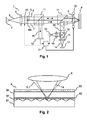
- An exemplary setup of a holographic storage system 1 is shown in Fig. 1.
- a source of coherent light e.g. a laser diode 2
- emits a light beam 3 which is collimated by a collimating lens 4.
- the light beam 3 is then divided into two separate light beams 6, 7.
- the division of the light beam 3 is achieved using a beam splitter BS.
- a spatial light modulator (SLM) 5 modulates one of the two beams, the so called "object beam" 6, to imprint a 2-dimensional data pattern.
- SLM spatial light modulator
- the holographic recording medium 9 is provided with a servo layer.
- the holographic storage system 1 includes a further light source 13 for generating a servo light beam 14.
- the servo light beam 14 is collimated by a further collimating lens 15 and coupled into the beam path of the object and reference beams 6, 7 by a second beam splitter 17.
- the servo light beam 14 is then focused onto the servo layer by the objective lens 8.
- the light beam reflected by the servo layer is again collimated by the objective lens 8 and directed towards a detector 20 by the second beam splitter 17 and a third beam splitter 18.
- a lens 19 focuses the reflected light beam onto the detector 20.
- the servo light beam 14 is focused onto the holographic recording medium 9 with the same objective lens 8 as the light beams 6, 7 used for holographic recording.
- the servo light beam 14 acts as a reference for the light beam 6, 7 used for holographic recording. Due to their different wavelengths and their different collimation the holographic light beams 6, 7 and the servo light beam 14 have different foci.
- the holographic storage system 1 is designed in such way that the foci of the holographic light beams 6, 7 are at their nominal position when the servo light beam 14 is focused correctly on the servo layer. A defocus is detected and corrected by the servo system 21 based on the servo light beam 14. The foci of the holographic light beams 6, 7 are moved in the same way, as all light beams 6, 7, 14 use the same objective lens 8.
- FIG. 2 A cross sectional view of the conditions inside the holographic recording medium 9 is shown in Fig. 2.
- the holographic recording medium 9 has a holographic layer 94 and a servo layer 92.
- the servo light beam 14 is focused onto a guiding structure of the servo layer 92, whereas the holographic light beams 6, 7 are focused into the holographic layer 94 as appropriate for the chosen holographic recording process.
- the servo layer 92 is arranged above a substrate 91 and separated from the holographic layer 94 by an intermediate layer 93, which is transparent for the wavelength of the servo light beam 14, but reflective for the wavelength of the holographic light beams 6, 7.
- Located above the holographic layer 94 is a cover layer 95.
Priority Applications (1)
| Application Number | Priority Date | Filing Date | Title |
|---|---|---|---|
| EP06119082A EP1890285A1 (de) | 2006-08-17 | 2006-08-17 | Verfahren zur Servosteuerung in einem holografischen Speichersystem |
Applications Claiming Priority (1)
| Application Number | Priority Date | Filing Date | Title |
|---|---|---|---|
| EP06119082A EP1890285A1 (de) | 2006-08-17 | 2006-08-17 | Verfahren zur Servosteuerung in einem holografischen Speichersystem |
Publications (1)
| Publication Number | Publication Date |
|---|---|
| EP1890285A1 true EP1890285A1 (de) | 2008-02-20 |
Family
ID=37670749
Family Applications (1)
| Application Number | Title | Priority Date | Filing Date |
|---|---|---|---|
| EP06119082A Withdrawn EP1890285A1 (de) | 2006-08-17 | 2006-08-17 | Verfahren zur Servosteuerung in einem holografischen Speichersystem |
Country Status (1)
| Country | Link |
|---|---|
| EP (1) | EP1890285A1 (de) |
Cited By (1)
| Publication number | Priority date | Publication date | Assignee | Title |
|---|---|---|---|---|
| CN101859575A (zh) * | 2009-04-10 | 2010-10-13 | 索尼光领公司 | 光斑位置控制设备和光斑位置控制方法 |
Citations (8)
| Publication number | Priority date | Publication date | Assignee | Title |
|---|---|---|---|---|
| DE4036615A1 (de) * | 1989-11-17 | 1991-05-23 | Sony Corp | Verfahren und vorrichtung zum speichern und lesen holographischer information |
| EP1065658A1 (de) * | 1998-02-27 | 2001-01-03 | Hideyoshi Horimai | Verfahren und vorrichtung für optische informationen, verfahren und vorrichtung zur wiedergabe von optischen informationen, vorrichtung zur aufzeichnung, wiedergabe von optischen informationen sowie optisches informationsaifzeichnungsmedium |
| US20020075776A1 (en) * | 2000-11-17 | 2002-06-20 | Matsushita Electric Industrial Co., Ltd. | Holographic optical information recording/reproducing device |
| WO2005057584A1 (en) * | 2003-12-08 | 2005-06-23 | Koninklijke Philips Electronics N.V. | Alignment of holographic image on detector |
| US20050195722A1 (en) * | 2004-02-25 | 2005-09-08 | Takayuki Tsukamoto | Reproducing apparatus, recording and reproducing apparatus and reproducing method |
| WO2005103842A2 (en) * | 2004-04-16 | 2005-11-03 | Dce Aprilis, Inc. | Calibration of holographic data storage systems using holographic media calibration features |
| EP1594127A2 (de) * | 2004-05-06 | 2005-11-09 | Daewoo Electronics Corporation | Holographischer ROM Leser mit Servosteuerung |
| US20060114792A1 (en) * | 2004-11-30 | 2006-06-01 | Kazushi Uno | Hologram recording medium and hologram record-reproduction device |
-
2006
- 2006-08-17 EP EP06119082A patent/EP1890285A1/de not_active Withdrawn
Patent Citations (8)
| Publication number | Priority date | Publication date | Assignee | Title |
|---|---|---|---|---|
| DE4036615A1 (de) * | 1989-11-17 | 1991-05-23 | Sony Corp | Verfahren und vorrichtung zum speichern und lesen holographischer information |
| EP1065658A1 (de) * | 1998-02-27 | 2001-01-03 | Hideyoshi Horimai | Verfahren und vorrichtung für optische informationen, verfahren und vorrichtung zur wiedergabe von optischen informationen, vorrichtung zur aufzeichnung, wiedergabe von optischen informationen sowie optisches informationsaifzeichnungsmedium |
| US20020075776A1 (en) * | 2000-11-17 | 2002-06-20 | Matsushita Electric Industrial Co., Ltd. | Holographic optical information recording/reproducing device |
| WO2005057584A1 (en) * | 2003-12-08 | 2005-06-23 | Koninklijke Philips Electronics N.V. | Alignment of holographic image on detector |
| US20050195722A1 (en) * | 2004-02-25 | 2005-09-08 | Takayuki Tsukamoto | Reproducing apparatus, recording and reproducing apparatus and reproducing method |
| WO2005103842A2 (en) * | 2004-04-16 | 2005-11-03 | Dce Aprilis, Inc. | Calibration of holographic data storage systems using holographic media calibration features |
| EP1594127A2 (de) * | 2004-05-06 | 2005-11-09 | Daewoo Electronics Corporation | Holographischer ROM Leser mit Servosteuerung |
| US20060114792A1 (en) * | 2004-11-30 | 2006-06-01 | Kazushi Uno | Hologram recording medium and hologram record-reproduction device |
Cited By (5)
| Publication number | Priority date | Publication date | Assignee | Title |
|---|---|---|---|---|
| CN101859575A (zh) * | 2009-04-10 | 2010-10-13 | 索尼光领公司 | 光斑位置控制设备和光斑位置控制方法 |
| EP2239734A2 (de) | 2009-04-10 | 2010-10-13 | Sony Optiarc Inc. | Vorrichtung zur Lichtpunktpositionssteuerung und Verfahren zur Lichtpunktpositionssteuerung |
| EP2239734A3 (de) * | 2009-04-10 | 2011-01-12 | Sony Optiarc Inc. | Vorrichtung zur Lichtpunktpositionssteuerung und Verfahren zur Lichtpunktpositionssteuerung |
| US8098560B2 (en) | 2009-04-10 | 2012-01-17 | Sony Optiarc Inc. | Light spot position control apparatus and light spot position control method |
| CN101859575B (zh) * | 2009-04-10 | 2012-11-28 | 索尼光领公司 | 光斑位置控制设备和光斑位置控制方法 |
Similar Documents
| Publication | Publication Date | Title |
|---|---|---|
| US7502151B2 (en) | Holographic recording and reconstructing apparatus and method | |
| KR100831859B1 (ko) | 홀로그램 기록 장치 | |
| US7283286B2 (en) | Hologram recording/reproducing device and optical unit | |
| US8134765B2 (en) | Hologram recording and reconstruction apparatus | |
| JP5037391B2 (ja) | 光ピックアップ、光情報記録再生装置および光学的情報記録再生方法 | |
| JP4919790B2 (ja) | 波長制御方法、ホログラム情報処理装置およびホログラム記録媒体 | |
| US20080309998A1 (en) | Hologram element deflecting optical beam, hologram element fabricating apparatus, hologram element fabricating method, deflection optical unit, and information recording apparatus and information reconstructing apparatus using deflection optical unit | |
| US7990830B2 (en) | Optical pickup, optical information recording apparatus and optical information recording and reproducing apparatus using the optical pickup | |
| US8787136B2 (en) | Holographic memory apparatus and method for adjusting incident angle of reference beam | |
| US7876482B2 (en) | Method for wavelength mismatch compensation in a holographic storage system | |
| US7729224B2 (en) | Optical information reproducing apparatus and optical information reproducing method using the same | |
| US20080123506A1 (en) | Optical information recording/reproducing apparatus | |
| JP2006209081A (ja) | ホログラム記録再生装置及び光学ユニット | |
| US20130128327A1 (en) | Optical information recording/ reproducing apparatus, optical information recording/ reproducing method, and optical information recording medium | |
| EP1890285A1 (de) | Verfahren zur Servosteuerung in einem holografischen Speichersystem | |
| EP1850336B1 (de) | Optisches Informationswiedergabegerät und optisches Informationsaufzeichnungsgerät unter Verwendung von Holografie | |
| JP6158339B2 (ja) | ホログラム再生装置、ホログラム再生方法 | |
| KR101193097B1 (ko) | 광 데이터 저장 매체로부터 판독하고 상기 광 데이터 저장 매체에 기록하기 위한 장치 | |
| JP6894110B2 (ja) | ホログラム記録再生装置 | |
| JP2006084526A (ja) | ホログラム再生装置及びホログラム再生方法 | |
| EP2290646A1 (de) | Positionskalibrierung eines holografischen Speichermediums | |
| CN105074583A (zh) | 全息记录再现装置和角度复用记录再现方式 | |
| KR100767940B1 (ko) | 광정보 재생장치, 광정보 기록재생장치 및 이를 이용한저장매체의 기울기검출방법 | |
| EP2290474A1 (de) | Neigungsausgleich für ein holografisches Speichersystem | |
| JP2017147010A (ja) | 光情報記録再生装置、ホログラム記録再生方法 |
Legal Events
| Date | Code | Title | Description |
|---|---|---|---|
| PUAI | Public reference made under article 153(3) epc to a published international application that has entered the european phase |
Free format text: ORIGINAL CODE: 0009012 |
|
| AK | Designated contracting states |
Kind code of ref document: A1 Designated state(s): AT BE BG CH CY CZ DE DK EE ES FI FR GB GR HU IE IS IT LI LT LU LV MC NL PL PT RO SE SI SK TR |
|
| AX | Request for extension of the european patent |
Extension state: AL BA HR MK YU |
|
| AKX | Designation fees paid | ||
| STAA | Information on the status of an ep patent application or granted ep patent |
Free format text: STATUS: THE APPLICATION IS DEEMED TO BE WITHDRAWN |
|
| 18D | Application deemed to be withdrawn |
Effective date: 20080821 |
|
| REG | Reference to a national code |
Ref country code: DE Ref legal event code: 8566 |