EP1890177B1 - Device for fixing a vitroceramic or ceramic mirror to a structure fitted on board a spacecraft operating at cryogenic temperature - Google Patents
Device for fixing a vitroceramic or ceramic mirror to a structure fitted on board a spacecraft operating at cryogenic temperature Download PDFInfo
- Publication number
- EP1890177B1 EP1890177B1 EP07113076A EP07113076A EP1890177B1 EP 1890177 B1 EP1890177 B1 EP 1890177B1 EP 07113076 A EP07113076 A EP 07113076A EP 07113076 A EP07113076 A EP 07113076A EP 1890177 B1 EP1890177 B1 EP 1890177B1
- Authority
- EP
- European Patent Office
- Prior art keywords
- clamping component
- assembly according
- protrusion
- mirror
- fixing
- Prior art date
- Legal status (The legal status is an assumption and is not a legal conclusion. Google has not performed a legal analysis and makes no representation as to the accuracy of the status listed.)
- Active
Links
- 239000000919 ceramic Substances 0.000 title claims description 4
- 239000011521 glass Substances 0.000 claims abstract description 21
- 239000000463 material Substances 0.000 claims abstract description 9
- 229910001374 Invar Inorganic materials 0.000 claims abstract description 5
- 229910052782 aluminium Inorganic materials 0.000 claims abstract description 5
- XAGFODPZIPBFFR-UHFFFAOYSA-N aluminium Chemical compound [Al] XAGFODPZIPBFFR-UHFFFAOYSA-N 0.000 claims abstract description 5
- PCHJSUWPFVWCPO-UHFFFAOYSA-N gold Chemical compound [Au] PCHJSUWPFVWCPO-UHFFFAOYSA-N 0.000 claims abstract description 3
- 239000010931 gold Substances 0.000 claims abstract description 3
- 229910052737 gold Inorganic materials 0.000 claims abstract description 3
- 239000004411 aluminium Substances 0.000 claims description 2
- 239000007779 soft material Substances 0.000 claims description 2
- 210000004027 cell Anatomy 0.000 claims 3
- 210000003850 cellular structure Anatomy 0.000 claims 1
- 239000002241 glass-ceramic Substances 0.000 description 3
- PXHVJJICTQNCMI-UHFFFAOYSA-N Nickel Chemical compound [Ni] PXHVJJICTQNCMI-UHFFFAOYSA-N 0.000 description 2
- 241001639412 Verres Species 0.000 description 2
- 230000006835 compression Effects 0.000 description 2
- 238000007906 compression Methods 0.000 description 2
- 229920000049 Carbon (fiber) Polymers 0.000 description 1
- 229910001030 Iron–nickel alloy Inorganic materials 0.000 description 1
- 239000006094 Zerodur Substances 0.000 description 1
- 230000000903 blocking effect Effects 0.000 description 1
- 239000004917 carbon fiber Substances 0.000 description 1
- 230000001413 cellular effect Effects 0.000 description 1
- 230000000295 complement effect Effects 0.000 description 1
- 230000007547 defect Effects 0.000 description 1
- 230000010354 integration Effects 0.000 description 1
- 229910052751 metal Inorganic materials 0.000 description 1
- 239000002184 metal Substances 0.000 description 1
- 239000007769 metal material Substances 0.000 description 1
- VNWKTOKETHGBQD-UHFFFAOYSA-N methane Chemical compound C VNWKTOKETHGBQD-UHFFFAOYSA-N 0.000 description 1
- 229910052759 nickel Inorganic materials 0.000 description 1
- 239000013585 weight reducing agent Substances 0.000 description 1
Images


Classifications
-
- G—PHYSICS
- G02—OPTICS
- G02B—OPTICAL ELEMENTS, SYSTEMS OR APPARATUS
- G02B7/00—Mountings, adjusting means, or light-tight connections, for optical elements
- G02B7/18—Mountings, adjusting means, or light-tight connections, for optical elements for prisms; for mirrors
- G02B7/182—Mountings, adjusting means, or light-tight connections, for optical elements for prisms; for mirrors for mirrors
- G02B7/183—Mountings, adjusting means, or light-tight connections, for optical elements for prisms; for mirrors for mirrors specially adapted for very large mirrors, e.g. for astronomy, or solar concentrators
-
- F—MECHANICAL ENGINEERING; LIGHTING; HEATING; WEAPONS; BLASTING
- F16—ENGINEERING ELEMENTS AND UNITS; GENERAL MEASURES FOR PRODUCING AND MAINTAINING EFFECTIVE FUNCTIONING OF MACHINES OR INSTALLATIONS; THERMAL INSULATION IN GENERAL
- F16B—DEVICES FOR FASTENING OR SECURING CONSTRUCTIONAL ELEMENTS OR MACHINE PARTS TOGETHER, e.g. NAILS, BOLTS, CIRCLIPS, CLAMPS, CLIPS OR WEDGES; JOINTS OR JOINTING
- F16B2/00—Friction-grip releasable fastenings
- F16B2/02—Clamps, i.e. with gripping action effected by positive means other than the inherent resistance to deformation of the material of the fastening
- F16B2/06—Clamps, i.e. with gripping action effected by positive means other than the inherent resistance to deformation of the material of the fastening external, i.e. with contracting action
- F16B2/12—Clamps, i.e. with gripping action effected by positive means other than the inherent resistance to deformation of the material of the fastening external, i.e. with contracting action using sliding jaws
Definitions
- the field of the invention is that of embedded mirrors aboard spacecraft of the observation satellite type.
- some missions involve having telescopes operating at cryogenic temperatures of the order of 100 ° K, in a range of visible wavelengths.
- Optics, especially large primary mirrors are generally glass-ceramic or ceramic and more specifically in Zérodur glass Schott society that has the great advantage of having an extremely low coefficient of thermal expansion.
- the embedded mirrors of large dimensions can typically be structures greater than 1 meter in size and of the order of a few centimeters, they undergo large temperature variations during operational operation (in orbit) and very strong constraints during the launch phase from the ground to their station in space.
- the figure 1 illustrates an example of a mirror Zerodur 1, ultra light structure of the order of 36kg / m 2 with three attachment points 3 inserted into cells 2 of a honeycomb structure for an onboard weight reduction.
- the mirror 1 comprising a cellular surface is generally fixed on a structure such as that illustrated in FIG. figure 2 comprising a support structure (panel or frame) 4 may in particular be made of carbon fiber. It can be fixed to this support structure by means of fixing devices 3 of the mirror which can advantageously be three in number (isostatic support) and comprising means 5 for fixing / connecting these devices on the support panel (stiff parts on 2 axes and flexible on all the other components).
- the figure 3 illustrates a mechanical fastening device according to the prior art for fixing the mirror to the support panel.
- the fixing device 3 comprises a conical piece which exerts a pressure on two pads 6 in a direction Dx parallel to the plane of the mirror.
- the disadvantage of this type of fastening device lies in the stresses exerted within the glass, which in this case are exerted in tension. and especially largely in flexion while the particular resistance of the glass-ceramic to this type of constraints is not very high. The problem is all the more crucial as the fixing device must be able to withstand the vibration loads inherent to the launching phase.
- the document US 5917644 shows a mirror fixing device implementing compressive stresses.
- the present invention proposes a fixing device implementing constraints of the pure compression type, that is to say in a direction perpendicular to the direction Dx, the resistance of the glass to this type of stress being much better. the resistance of glass to tensile or shear stresses.
- the subject of the invention is an assembly comprising a glass-ceramic or ceramic mirror and a device for fixing the mirror to a structure on board a spacecraft, said mirror comprising a honeycomb structure, characterized in that at least a cell having a glass protrusion having an intermediate portion in a direction perpendicular to the plane of the mirror from the base of the cell and an end portion called heel, perpendicular to said intermediate portion (the heel) so as to constitute an excrescence in the form of of T, said device comprises a clamping piece which grips the end portion of the protuberance (the heel) in a direction parallel to the intermediate portion and means for fixing said clamping piece to the onboard structure.
- the advantages of the device according to the invention reside in particular in the fact of supporting the vibration loads due to the launch (at ambient temperature) and then, in cold operation, of releasing the tensions in order to limit as much as possible the deformations induced at the level of the active face of the mirror.
- the clamping piece comprises a main opening of the same shape as the glass protrusion (the main block).
- the clamping piece further comprises second openings in a direction parallel to the intermediate portion of the protuberance, said openings being equipped with screws for locking the clamp against the protrusion of glass.
- the fixing device further comprises pads to ensure contact between the end portion of the protrusion (the heel) and the clamping piece.
- it can comprise two sets of pads in contact with each of the surfaces of the terminal portion of the outgrowth
- the mirror intended to be fixed to a structure on board a spacecraft comprises a lightened alveolar structure.
- the interface of the mirror with the fixing device consists of glass protuberances each comprising an intermediate portion and a terminal portion in the form of a heel. Both wings of this heel are taken “tweezers” by a clamping piece with screws.
- the clamping forces only create compression stresses in the glass in a direction Dy perpendicular to the heel, illustrated in FIG. figure 4 which shows schematically a glass protrusion 11, taken in the clamping piece 33, having clamping screws 77.
- the fixing device comprising the clamping screws 77 inserted in the clamping piece 33 and illustrated in FIG. Figures 5a, 5b and 5c .
- the clamping piece 33 has a main opening 13 into which can be introduced (sliding along Z axis) the glass protrusion. It also comprises second openings 73 in a direction Dy perpendicular to the plane of the mirror and intended to receive the clamping screws 77.
- This fixing device comprises pads 66 intended to ensure contact between the clamping piece and the glass piece and are useful for distributing the stresses. More specifically two sets of pads are to be in contact with both sides of the end portion of the heel.
- the second openings may also include force cells 88, making it possible to precisely know the applied force and consequently to control the stresses during tightening of the screws, prior to the launching phase in space.
- it may be metal cylinder equipped with strain gauges and calibrated beforehand.
- third openings 93 in a direction Dx parallel to the plane of the mirror, allowing the introduction of screws 99 abutting against the pads: blocking of the pads when installing before tightening the screws 77.
- the screws 93 must be loosened when tightening the screws 77 and in operational operation.
- the mechanical (vibration) loads at ambient temperature are taken up axially by positive stop and tangentially by friction.
- the clamping forces are canceled by varying the thicknesses and the thermoelastic expansion coefficients that enter the assembly forming the clamping.
- a minimum voltage is aimed to just keep the mirror operational without injecting a force that can deform the active face.
- the clamping piece comprises fourth openings, for example four openings 35, intended to cooperate with means for fixing this clamping piece on the embedded structure.
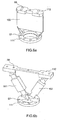
- these fixing means can be for example those illustrated in FIG. FIG. 6a or FIG. 6b .
- These are so-called blade type 100 or "A-shape" type fastening means of blades 101 and 102 between a first base 111 and a second base 112 and having openings. 57 (screw holes) of the base 111, it is possible to introduce screws intended to be screwed into the fourth openings of the clamping piece.through the eighth openings 58 (idem) of the second base 112 can be introduced screws intended to be screwed on the embedded structure corresponding to the panel 4 of the figure 2 .
- the device comprises a clamping piece of metal material with a low coefficient of thermal expansion.
- Invar has a low coefficient of the order of 1.5 ppm / ° K and is particularly suitable for this type of application.
- the fixing device comprises pads which can advantageously be made of an aluminum type material.
- the surface of the pads can advantageously be covered with a thin layer of soft gold-type material that allows to play the role of elastic seal.
- these dimensions may be chosen to be equal to approximately 15 mm and 20 mm, so as to obtain good ratios between the various stresses to which the end portion of the glass protrusion is subjected.
Abstract
Description
Le domaine de l'invention est celui des miroirs embarqués à bord d'engins spatiaux de type satellite d'observation. Pour ce type d'application, certaines missions impliquent d'avoir des télescopes fonctionnant à des températures cryogéniques de l'ordre de 100° K, dans un domaine de longueurs d'onde visibles. Les optiques, notamment les grands miroirs primaires, sont généralement en vitrocéramique ou céramique et plus précisément en Zérodur, verre de la société Schott qui présente le grand intérêt d'avoir un coefficient de dilatation thermique extrêmement faible.The field of the invention is that of embedded mirrors aboard spacecraft of the observation satellite type. For this type of application, some missions involve having telescopes operating at cryogenic temperatures of the order of 100 ° K, in a range of visible wavelengths. Optics, especially large primary mirrors, are generally glass-ceramic or ceramic and more specifically in Zérodur glass Schott society that has the great advantage of having an extremely low coefficient of thermal expansion.
Les miroirs embarqués de grandes dimensions pouvant typiquement être des structures d'envergure supérieure à 1 mètre et d'épaisseur de l'ordre de quelques centimètres, ils subissent de fortes variations de température lors du fonctionnement opérationnel (en orbit) et de très fortes contraintes mécaniques lors de la phase de lancement depuis le sol jusqu'à leur station dans l'espace. La
Le miroir 1 comprenant une surface alvéolaire est généralement fixé sur une structure telle que celle illustrée en
La
Le document
Dans ce contexte, la présente invention propose un dispositif de fixation mettant en oeuvre des contraintes de type compression pure, c'est-à-dire dans une direction perpendiculaire à la direction Dx, la résistance du verre à ce type de contraintes étant bien meilleure que la résistance du verre aux contraintes de traction ou de cisaillement.In this context, the present invention proposes a fixing device implementing constraints of the pure compression type, that is to say in a direction perpendicular to the direction Dx, the resistance of the glass to this type of stress being much better. the resistance of glass to tensile or shear stresses.
Plus précisément l'invention a pour objet un assemblage comportant un miroir en vitrocéramique ou céramique et un dispositif de fixation du miroir sur une structure embarquée à bord d'un engin spatial, ledit miroir comportant une structure alvéolaire, caractérisé en ce qu'au moins une alvéole comportant une excroissance de verre présentant une partie intermédiaire dans une direction perpendiculaire au plan du miroir depuis la base de l'alvéole et une partie terminale appelée talon, perpendiculaire à ladite partie intermédiaire (le talon) de manière à constituer une excroissance en forme de T, ledit dispositif comprend une pièce de serrage venant pincer la partie terminale de l'excroissance (le talon) selon une direction parallèle à la partie intermédiaire et des moyens de fixation de ladite pièce de serrage sur la structure embarquée.More specifically, the subject of the invention is an assembly comprising a glass-ceramic or ceramic mirror and a device for fixing the mirror to a structure on board a spacecraft, said mirror comprising a honeycomb structure, characterized in that at least a cell having a glass protrusion having an intermediate portion in a direction perpendicular to the plane of the mirror from the base of the cell and an end portion called heel, perpendicular to said intermediate portion (the heel) so as to constitute an excrescence in the form of of T, said device comprises a clamping piece which grips the end portion of the protuberance (the heel) in a direction parallel to the intermediate portion and means for fixing said clamping piece to the onboard structure.
Les avantages du dispositif selon l'invention résident notamment dans le fait de supporter les charges de vibration dues au lancement (à température ambiante) et ensuite, en fonctionnement à froid, de libérer les tensions afin de limiter au maximum les déformations induites au niveau de la face active du miroir.The advantages of the device according to the invention reside in particular in the fact of supporting the vibration loads due to the launch (at ambient temperature) and then, in cold operation, of releasing the tensions in order to limit as much as possible the deformations induced at the level of the active face of the mirror.
Selon une variante de l'invention, la pièce de serrage comprend une ouverture principale de même forme que l'excroissance de verre (le bloc principal).According to a variant of the invention, the clamping piece comprises a main opening of the same shape as the glass protrusion (the main block).
Selon une variante de l'invention, la pièce de serrage comprend en outre des secondes ouvertures selon une direction parallèle à la partie intermédiaire de l'excroissance, lesdites ouvertures étant équipées de vis pour bloquer la pièce de serrage contre l'excroissance de verre.According to a variant of the invention, the clamping piece further comprises second openings in a direction parallel to the intermediate portion of the protuberance, said openings being equipped with screws for locking the clamp against the protrusion of glass.
Selon l'invention, le dispositif de fixation comprend en outre des patins pour assurer le contact entre la partie terminale de l'excroissance (le talon) et la pièce de serrage.According to the invention, the fixing device further comprises pads to ensure contact between the end portion of the protrusion (the heel) and the clamping piece.
Avantageusement, il peut comprendre deux séries de patins en contact avec chacune des surfaces de la partie terminale de l'excroissanceAdvantageously, it can comprise two sets of pads in contact with each of the surfaces of the terminal portion of the outgrowth
Selon l'invention, les patins comprennent une première partie en contact avec la partie terminale de l'excroissance présentant une face plane et une face convexe et une seconde partie présentant une face concave complémentaire à celle de la première partie (réalisant ainsi une tête pivotante) :
- Selon une variante de l'invention, les patins sont réalisés dans un matériau à fort coefficient de dilatation thermique type aluminium.
- Selon une variante de l'invention, la pièce de serrage est réalisée en un matériau à très faible coefficient de dilatation thermique de type alliage fer nickel de type Invar (Sté Goodfellow).
- Selon une variante de l'invention, la surface des patins en contact avec la partie terminale de l'excroissance comprend en outre une couche de matériau tendre de type or permettant d'améliorer le contact par rapport aux états de surface et donc d'homogénéiser les contraintes. Avantageusement, la pièce de serrage peut comprendre en outre des cellules de force entre les vis et les patins.
- Selon une variante de l'invention, la pièce de serrage comprend en outre des troisièmes ouvertures selon une direction perpendiculaire à celle des secondes ouvertures et pouvant recevoir des vis de maintien au montage, en contact avec les patins.
- Selon une variante de l'invention, la pièce de serrage comprend des quatrièmes ouvertures destinées à recevoir des moyens pour fixer ladite pièce de serrage sur la structure embarquée.
- According to a variant of the invention, the pads are made of a material with a high coefficient of thermal expansion type aluminum.
- According to a variant of the invention, the clamping piece is made of a material with a very low coefficient of thermal expansion of iron-nickel alloy type Invar (Goodfellow St).
- According to a variant of the invention, the surface of the pads in contact with the end portion of the protrusion further comprises a layer of soft material of the gold type making it possible to improve the contact with respect to the surface states and thus to homogenize constraints. Advantageously, the clamping piece may further comprise force cells between the screws and the pads.
- According to a variant of the invention, the clamping piece further comprises third openings in a direction perpendicular to that of the second openings and can receive mounting screws on mounting, in contact with the pads.
- According to a variant of the invention, the clamping piece comprises fourth openings intended to receive means for fixing said clamping piece on the embedded structure.
L'invention sera mieux comprise à la lecture de la description qui va suivre donnée à titre non limitatif et grâce aux figures annexées parmi lesquelles :
- la
figure 1 illustre un exemple de miroir spatial selon l'art connu destiné à être fixé sur une structure embarquée ; - la
figure 2 illustre un exemple de l'ensemble embarqué sur un engin spatial comprenant un miroir et une structure de fixation, selon l'art connu ; - la
figure 3 illustre un exemple de dispositif de fixation de miroir selon l'art connu ; - la
figure 4 illustre un exemple de dispositif de fixation sur un miroir selon l'invention; - les
figures 5a, 5b et 5c illustrent respectivement une vue en perspective, en coupe et de dessus de l'exemple du dispositif montré enfigure 4 ; - les
figures 6a et 6b illustrent deux exemples de moyens de fixation du dispositif de fixation selon l'invention, sur une structure embarquée à bord d'un engin spatial ; - la figure 7 illustre une vue éclatée des patins utilisés dans un exemple de dispositif de fixation selon l'invention.
- the
figure 1 illustrates an example of a spatial mirror according to the known art intended to be fixed on an embedded structure; - the
figure 2 illustrates an example of the assembly on board a spacecraft comprising a mirror and a fastening structure, according to the prior art; - the
figure 3 illustrates an example of a mirror fixing device according to the prior art; - the
figure 4 illustrates an example of a fixing device on a mirror according to the invention; - the
Figures 5a, 5b and 5c respectively show a perspective view, in section and from above of the example of the device shown in FIG.figure 4 ; - the
Figures 6a and 6b illustrate two examples of fastening means of the fastening device according to the invention, on a structure onboard a spacecraft; - Figure 7 illustrates an exploded view of the pads used in an exemplary fastener according to the invention.
Selon l'invention, le miroir destiné à être fixé à une structure embarquée à bord d'un engin spatial comporte une structure allégée alvéolaire. L'interface du miroir avec le dispositif de fixation est constituée par des excroissances de verre comportant chacune une partie intermédiaire et une partie terminale en forme de talon. Les deux ailes de ce talon sont prises « en pincette » par une pièce de serrage comportant des vis. Les efforts de serrage ne créent que des contraintes de compression dans le verre selon une direction Dy perpendiculaire au talon, illustré en
Nous allons décrire ci-après plus en détails le dispositif de fixation comprenant les vis de serrage 77 insérées dans la pièce de serrage 33 et illustré en
Ce dispositif de fixation comporte des patins 66 destinés à venir assurer le contact entre la pièce de serrage et la pièce en verre et sont utiles pour répartir les contraintes. Plus précisément deux séries de patins sont à être en contact avec les deux faces de la partie terminale du talon.This fixing device comprises
Par ailleurs, les secondes ouvertures peuvent également comprendre des cellules de force 88, permettant de connaître précisément l'effort appliqué et par suite de maîtriser les contraintes lors du serrage des vis, préalablement à la phase de lancement dans l'espace. Typiquement il peut s'agir de cylindre métallique équipé de jauges de contrainte et étalonné au préalable.Moreover, the second openings may also include
Afin de faciliter la phase d'intégration du système, il est également prévu selon la variante décrite, des troisièmes ouvertures 93 selon une direction Dx parallèle au plan du miroir, permettant l'introduction de vis 99 venant buter contre les patins : blocage des patins lors de la mise en place avant le serrage des vis 77. Les vis 93 doivent être desserrées lors du serrage des vis 77 et en fonctionnement opérationnel.To facilitate the integration phase of the system, it is also provided according to the variant described,
Grâce à l'ensemble de ces paramètres de serrage, les charges mécaniques (de vibration) à température ambiante sont reprises axialement par butée positive et tangentiellement par frottement. A température cryogénique, on annule les efforts de serrage en jouant sur les épaisseurs et les coefficients de dilatation thermoélastique qui rentrent dans l'assemblage réalisant le serrage. Une tension minimum est visée pour juste maintenir le miroir en opérationnel sans injecter d'effort susceptible de déformer la face active.Thanks to all these clamping parameters, the mechanical (vibration) loads at ambient temperature are taken up axially by positive stop and tangentially by friction. At cryogenic temperature, the clamping forces are canceled by varying the thicknesses and the thermoelastic expansion coefficients that enter the assembly forming the clamping. A minimum voltage is aimed to just keep the mirror operational without injecting a force that can deform the active face.
Par ailleurs, la pièce de serrage comprend des quatrièmes ouvertures, par exemple quatre ouvertures 35, destinées à coopérer avec des moyens pour fixer cette pièce de serrage sur la structure embarquée.Furthermore, the clamping piece comprises fourth openings, for example four
Typiquement ces moyens de fixation peuvent être par exemple ceux illustrés en
Le dispositif comprend une pièce de serrage en matériau métallique de faible coefficient de dilatation thermique. Par exemple l'Invar possède un coefficient faible de l'ordre 1,5 ppm/°K et est particulièrement adapté à ce type d'application.The device comprises a clamping piece of metal material with a low coefficient of thermal expansion. For example Invar has a low coefficient of the order of 1.5 ppm / ° K and is particularly suitable for this type of application.
Pour minimiser les contraintes auxquelles est soumis le miroir, le dispositif de fixation comprend des patins pouvant avantageusement être en un matériau de type Aluminium.To minimize the stresses to which the mirror is subjected, the fixing device comprises pads which can advantageously be made of an aluminum type material.
De plus, ces patins sont avantageusement constitués en deux parties comme illustré en figure 7 qui fournit une vue éclatée des patins utilisés dans le dispositif de l'invention.
- une première partie 66a présente une surface plane destinée à être en contact avec la partie terminale de verre et une surface convexe ;
- une seconde partie 66b comportant une surface concave,
les deux parties
- a
first portion 66a has a planar surface for contact with the end portion of glass and a convex surface; - a
second portion 66b having a concave surface,
the two
Pour favoriser encore le contact entre les patins et la pièce en verre, la surface des patins peut avantageusement être recouverte d'une fine couche de matériau tendre type or qui permet de jouer le rôle de joint élastique.To further promote the contact between the pads and the glass piece, the surface of the pads can advantageously be covered with a thin layer of soft gold-type material that allows to play the role of elastic seal.
Il est à noter par ailleurs que pour ne pas fragiliser les points de contact du miroir matérialisés par les excroissances de verre, il est important de conférer un bon ratio entre épaisseur et longueur au niveau du talon. Ainsi et avantageusement ces dimensions peuvent être choisies égales à environ 15 mm et 20 mm, de manière à obtenir de bons rapports entre les différentes contraintes auxquelles est soumise la partie terminale de l'excroissance de verre.It should also be noted that in order not to weaken the points of contact of the mirror materialized by the glass protuberances, it is important to confer a good ratio between thickness and length at the heel. Thus, and advantageously, these dimensions may be chosen to be equal to approximately 15 mm and 20 mm, so as to obtain good ratios between the various stresses to which the end portion of the glass protrusion is subjected.
Claims (10)
- Assembly comprising a vitroceramic or ceramic mirror and a device for fixing the mirror to a structure fitted on board a spacecraft, said mirror having a cellular structure, the assembly being characterized in that at least one cell has a glass protrusion (11) with an intermediate part in a direction (Dy) perpendicular to the plane of the mirror from the base of the cell and a terminal part perpendicular to said intermediate part in such a way as to create a T-shaped protrusion, in that said fixing device comprises a clamping component (33) that grips the terminal part of the protrusion in a direction parallel to the intermediate part and fixing means (5) for fixing said clamping component to the on-board structure, and in that it also comprises feet (66) for creating contact between the terminal part of the protrusion and the clamping component, the feet comprising a pivoting head consisting of a first part (66a) in contact with the terminal part of the protrusion having a planar face and a convex face, and a second part (66b) having a concave face which fits the face of the first part, thus creating a pivoting head.
- Assembly according to Claim 1, characterized in that the clamping component comprises a main opening (13) of the same shape as the glass protrusion.
- Assembly according to Claim 2, characterized in that the clamping component also comprises second openings (73) provided with screws (77) for locking the clamping component against the glass protrusion.
- Assembly according to one of Claims 1 to 3, characterized in that the feet are made of a material with a high coefficient of thermal expansion, such as aluminium.
- Assembly according to one of Claims 1 to 4, characterized in that the clamping component is made of a material with a low coefficient of thermal expansion, such as Invar.
- Assembly according to one of Claims 1 to 5, characterized in that the surface of the feet in contact with the terminal part of the protrusion also comprises a layer of soft material such as gold to improve the contact compared with the surface states and hence equalize the stresses.
- Assembly according to one of Claims 1 to 6, characterized in that the clamping component also comprises load cells (88) between the screws and the feet.
- Assembly according to either of Claims 6 and 7, characterized in that the clamping component also comprises third openings (93) in a direction perpendicular to that of the first or primary openings and able to receive screws for holding the feet on the mounting (99) .
- Assembly according to one of Claims 1 to 8, characterized in that the clamping component comprises fourth openings (35) designed to take means (5) for fixing said clamping component to the on-board structure.
- Structure on board a spacecraft comprising at least one assembly according to any one of the preceding claims.
Applications Claiming Priority (1)
| Application Number | Priority Date | Filing Date | Title |
|---|---|---|---|
| FR0653102A FR2904433B1 (en) | 2006-07-25 | 2006-07-25 | DEVICE FOR FASTENING A VITROCERAMIC OR CERAMIC MIRROR ON A STRUCTURE ON BOARD A SPATIAL ENGINE OPERATING AT CRYOGENIC TEMPERATURE |
Publications (2)
| Publication Number | Publication Date |
|---|---|
| EP1890177A1 EP1890177A1 (en) | 2008-02-20 |
| EP1890177B1 true EP1890177B1 (en) | 2009-11-18 |
Family
ID=37734828
Family Applications (1)
| Application Number | Title | Priority Date | Filing Date |
|---|---|---|---|
| EP07113076A Active EP1890177B1 (en) | 2006-07-25 | 2007-07-25 | Device for fixing a vitroceramic or ceramic mirror to a structure fitted on board a spacecraft operating at cryogenic temperature |
Country Status (5)
| Country | Link |
|---|---|
| EP (1) | EP1890177B1 (en) |
| AT (1) | ATE449360T1 (en) |
| DE (1) | DE602007003276D1 (en) |
| ES (1) | ES2335935T3 (en) |
| FR (1) | FR2904433B1 (en) |
Cited By (1)
| Publication number | Priority date | Publication date | Assignee | Title |
|---|---|---|---|---|
| US10926431B2 (en) | 2013-06-25 | 2021-02-23 | Schott Ag | Tool head and glass or glass ceramic article producible using the tool head |
Families Citing this family (6)
| Publication number | Priority date | Publication date | Assignee | Title |
|---|---|---|---|---|
| FR2933782B1 (en) * | 2008-07-11 | 2010-08-13 | Thales Sa | DEVICE FOR CORRECTING THE OPTICAL DEFECTS OF A TELESCOPE MIRROR |
| DE102008039042B4 (en) * | 2008-08-21 | 2011-04-14 | Schott Ag | Substrate for a mirror carrier with reduced weight and mirror with weight-reduced mirror carrier |
| DE102009005400B4 (en) * | 2009-01-19 | 2011-04-07 | Schott Ag | Substrate for a mirror support, made of glass or glass ceramic |
| JP6079906B2 (en) * | 2016-01-06 | 2017-02-15 | 三菱電機株式会社 | Lightweight mirror |
| CN109625340B (en) * | 2018-12-19 | 2022-07-29 | 长沙新材料产业研究院有限公司 | Loaded object loading device and loaded object damping packaging method |
| CN112782832A (en) * | 2021-01-19 | 2021-05-11 | 长光卫星技术有限公司 | Carbon fiber honeycomb type main bearing plate |
Family Cites Families (6)
| Publication number | Priority date | Publication date | Assignee | Title |
|---|---|---|---|---|
| US4763991A (en) * | 1987-08-10 | 1988-08-16 | Litton Systems, Inc. | Adjustable six degree of freedom mount for optical components |
| FR2641344B1 (en) * | 1988-12-29 | 1991-04-19 | Aerospatiale | DEVICE FOR FIXING A FRAGILE OBJECT SUCH AS A MIRROR |
| US5076700A (en) * | 1990-12-20 | 1991-12-31 | Litton Systems, Inc. | Bonded lightweight mirror structure |
| FR2761486B1 (en) * | 1997-03-28 | 1999-05-21 | Centre Nat Etd Spatiales | DEVICE FOR MICROMETRIC POSITIONING OF A SPACE OPTICAL ELEMENT SUPPORT ACCORDING TO SIX DEGREES OF FREEDOM |
| US5969892A (en) * | 1997-11-14 | 1999-10-19 | Ball Aerospace & Technologies Corp. | Motion reducing flexure structure |
| US5917644A (en) * | 1998-05-01 | 1999-06-29 | Raytheon Company | Integral high-energy-button deformable mirror |
-
2006
- 2006-07-25 FR FR0653102A patent/FR2904433B1/en not_active Expired - Fee Related
-
2007
- 2007-07-25 EP EP07113076A patent/EP1890177B1/en active Active
- 2007-07-25 DE DE602007003276T patent/DE602007003276D1/en active Active
- 2007-07-25 AT AT07113076T patent/ATE449360T1/en active
- 2007-07-25 ES ES07113076T patent/ES2335935T3/en active Active
Cited By (1)
| Publication number | Priority date | Publication date | Assignee | Title |
|---|---|---|---|---|
| US10926431B2 (en) | 2013-06-25 | 2021-02-23 | Schott Ag | Tool head and glass or glass ceramic article producible using the tool head |
Also Published As
| Publication number | Publication date |
|---|---|
| FR2904433B1 (en) | 2008-11-28 |
| FR2904433A1 (en) | 2008-02-01 |
| EP1890177A1 (en) | 2008-02-20 |
| ATE449360T1 (en) | 2009-12-15 |
| ES2335935T3 (en) | 2010-04-06 |
| DE602007003276D1 (en) | 2009-12-31 |
Similar Documents
| Publication | Publication Date | Title |
|---|---|---|
| EP1890177B1 (en) | Device for fixing a vitroceramic or ceramic mirror to a structure fitted on board a spacecraft operating at cryogenic temperature | |
| EP1861311B1 (en) | Device and method for non-symmetrical mixed carbon-metal assembly | |
| EP2046636B1 (en) | Aircraft doorway | |
| EP1950392B1 (en) | Device for assembling two units, for example for a turbomachine stator | |
| EP2106364B1 (en) | Section of aircraft fuselage and aircraft including one such section | |
| FR3015431A1 (en) | PRIMARY STRUCTURE OF REINFORCED ATTACHING MAT. | |
| EP2435716B1 (en) | Device for temporarily connecting and pyrotechnically separating two assemblies | |
| WO2008096088A2 (en) | Aircraft cabin window assembly method | |
| EP3827207B1 (en) | Attachment device for a panel, in particular for a solar panel | |
| EP1355120B1 (en) | Device for provisionally connecting and pyrotechnically separating two elements, with no rupture | |
| WO2013110785A1 (en) | Device for attaching an optical member, attachment system and cryogenic device comprising such a device, method of manufacturing such a device and corresponding attachment method | |
| FR3041609A1 (en) | DEVICE FOR SEPARATION CONTROLLED BETWEEN TWO PIECES AND APPLICATION OF SUCH A DEVICE | |
| EP0898551A1 (en) | System for temporarily blocking the relative displacement of two bodies, following at least a preset direction | |
| EP3027512B1 (en) | Method and device for connecting and separating two elements with combined connecting and separating means | |
| EP2006951B1 (en) | Mechanical temperature compensation device for a waveguide with phase stability | |
| FR2813401A1 (en) | MECHANICAL HOLDING SYSTEM FOR A DEVICE WITH A SUBSTANTIALLY FLAT ELEMENT, IN PARTICULAR FOR A DISPLAY DEVICE WITH A LIQUID CRYSTAL DISPLAY | |
| FR2971233A1 (en) | Multilayer substrate for dampening panel structure of e.g. telecommunication satellite, has skins separated by honeycomb type structure comprising tubular cells, where one of cells is provided with damping element occupying interior of cell | |
| EP3523151B1 (en) | Lightweight support for a propulsion engine capable of limiting transverse forces | |
| FR3013684A1 (en) | SATELLITE CARRIER STRUCTURE COMPRISING A DAMPING LINK DEVICE | |
| EP3523553B1 (en) | Lightweight shim for a powertrain capable of limiting vertical forces | |
| EP3476717A1 (en) | Aircraft windscreen with integrated flange and load distribution inserts | |
| FR2903466A1 (en) | Floating nut system for aircraft, has locking effort taking ring that traverses screw passage hole for projecting face of main plate opposite to another face of main plate, and floating nut supported against ring | |
| EP2851917B1 (en) | Limit switch | |
| FR3127028A1 (en) | KIT FOR AN AIRCRAFT NACELLE AND COMPRISING A SUPPORT PANEL, THERMAL PROTECTION AND A FIXING SYSTEM | |
| FR3057216A1 (en) | COMPOUND BODY FOR MOTOR POWERS |
Legal Events
| Date | Code | Title | Description |
|---|---|---|---|
| PUAI | Public reference made under article 153(3) epc to a published international application that has entered the european phase |
Free format text: ORIGINAL CODE: 0009012 |
|
| AK | Designated contracting states |
Kind code of ref document: A1 Designated state(s): AT BE BG CH CY CZ DE DK EE ES FI FR GB GR HU IE IS IT LI LT LU LV MC MT NL PL PT RO SE SI SK TR |
|
| AX | Request for extension of the european patent |
Extension state: AL BA HR MK YU |
|
| 17P | Request for examination filed |
Effective date: 20080806 |
|
| 17Q | First examination report despatched |
Effective date: 20080905 |
|
| AKX | Designation fees paid |
Designated state(s): AT BE BG CH CY CZ DE DK EE ES FI FR GB GR HU IE IS IT LI LT LU LV MC MT NL PL PT RO SE SI SK TR |
|
| GRAP | Despatch of communication of intention to grant a patent |
Free format text: ORIGINAL CODE: EPIDOSNIGR1 |
|
| GRAS | Grant fee paid |
Free format text: ORIGINAL CODE: EPIDOSNIGR3 |
|
| GRAA | (expected) grant |
Free format text: ORIGINAL CODE: 0009210 |
|
| AK | Designated contracting states |
Kind code of ref document: B1 Designated state(s): AT BE BG CH CY CZ DE DK EE ES FI FR GB GR HU IE IS IT LI LT LU LV MC MT NL PL PT RO SE SI SK TR |
|
| REG | Reference to a national code |
Ref country code: GB Ref legal event code: FG4D Free format text: NOT ENGLISH |
|
| REG | Reference to a national code |
Ref country code: CH Ref legal event code: EP |
|
| REG | Reference to a national code |
Ref country code: IE Ref legal event code: FG4D |
|
| REF | Corresponds to: |
Ref document number: 602007003276 Country of ref document: DE Date of ref document: 20091231 Kind code of ref document: P |
|
| REG | Reference to a national code |
Ref country code: ES Ref legal event code: FG2A Ref document number: 2335935 Country of ref document: ES Kind code of ref document: T3 |
|
| LTIE | Lt: invalidation of european patent or patent extension |
Effective date: 20091118 |
|
| PG25 | Lapsed in a contracting state [announced via postgrant information from national office to epo] |
Ref country code: LT Free format text: LAPSE BECAUSE OF FAILURE TO SUBMIT A TRANSLATION OF THE DESCRIPTION OR TO PAY THE FEE WITHIN THE PRESCRIBED TIME-LIMIT Effective date: 20091118 Ref country code: PT Free format text: LAPSE BECAUSE OF FAILURE TO SUBMIT A TRANSLATION OF THE DESCRIPTION OR TO PAY THE FEE WITHIN THE PRESCRIBED TIME-LIMIT Effective date: 20100318 Ref country code: SE Free format text: LAPSE BECAUSE OF FAILURE TO SUBMIT A TRANSLATION OF THE DESCRIPTION OR TO PAY THE FEE WITHIN THE PRESCRIBED TIME-LIMIT Effective date: 20091118 Ref country code: IS Free format text: LAPSE BECAUSE OF FAILURE TO SUBMIT A TRANSLATION OF THE DESCRIPTION OR TO PAY THE FEE WITHIN THE PRESCRIBED TIME-LIMIT Effective date: 20100318 Ref country code: FI Free format text: LAPSE BECAUSE OF FAILURE TO SUBMIT A TRANSLATION OF THE DESCRIPTION OR TO PAY THE FEE WITHIN THE PRESCRIBED TIME-LIMIT Effective date: 20091118 |
|
| PG25 | Lapsed in a contracting state [announced via postgrant information from national office to epo] |
Ref country code: PL Free format text: LAPSE BECAUSE OF FAILURE TO SUBMIT A TRANSLATION OF THE DESCRIPTION OR TO PAY THE FEE WITHIN THE PRESCRIBED TIME-LIMIT Effective date: 20091118 Ref country code: LV Free format text: LAPSE BECAUSE OF FAILURE TO SUBMIT A TRANSLATION OF THE DESCRIPTION OR TO PAY THE FEE WITHIN THE PRESCRIBED TIME-LIMIT Effective date: 20091118 Ref country code: SI Free format text: LAPSE BECAUSE OF FAILURE TO SUBMIT A TRANSLATION OF THE DESCRIPTION OR TO PAY THE FEE WITHIN THE PRESCRIBED TIME-LIMIT Effective date: 20091118 Ref country code: CY Free format text: LAPSE BECAUSE OF FAILURE TO SUBMIT A TRANSLATION OF THE DESCRIPTION OR TO PAY THE FEE WITHIN THE PRESCRIBED TIME-LIMIT Effective date: 20091118 |
|
| REG | Reference to a national code |
Ref country code: IE Ref legal event code: FD4D |
|
| PG25 | Lapsed in a contracting state [announced via postgrant information from national office to epo] |
Ref country code: EE Free format text: LAPSE BECAUSE OF FAILURE TO SUBMIT A TRANSLATION OF THE DESCRIPTION OR TO PAY THE FEE WITHIN THE PRESCRIBED TIME-LIMIT Effective date: 20091118 Ref country code: DK Free format text: LAPSE BECAUSE OF FAILURE TO SUBMIT A TRANSLATION OF THE DESCRIPTION OR TO PAY THE FEE WITHIN THE PRESCRIBED TIME-LIMIT Effective date: 20091118 Ref country code: IE Free format text: LAPSE BECAUSE OF FAILURE TO SUBMIT A TRANSLATION OF THE DESCRIPTION OR TO PAY THE FEE WITHIN THE PRESCRIBED TIME-LIMIT Effective date: 20091118 Ref country code: RO Free format text: LAPSE BECAUSE OF FAILURE TO SUBMIT A TRANSLATION OF THE DESCRIPTION OR TO PAY THE FEE WITHIN THE PRESCRIBED TIME-LIMIT Effective date: 20091118 Ref country code: BG Free format text: LAPSE BECAUSE OF FAILURE TO SUBMIT A TRANSLATION OF THE DESCRIPTION OR TO PAY THE FEE WITHIN THE PRESCRIBED TIME-LIMIT Effective date: 20100218 |
|
| PG25 | Lapsed in a contracting state [announced via postgrant information from national office to epo] |
Ref country code: SK Free format text: LAPSE BECAUSE OF FAILURE TO SUBMIT A TRANSLATION OF THE DESCRIPTION OR TO PAY THE FEE WITHIN THE PRESCRIBED TIME-LIMIT Effective date: 20091118 Ref country code: CZ Free format text: LAPSE BECAUSE OF FAILURE TO SUBMIT A TRANSLATION OF THE DESCRIPTION OR TO PAY THE FEE WITHIN THE PRESCRIBED TIME-LIMIT Effective date: 20091118 |
|
| PLBE | No opposition filed within time limit |
Free format text: ORIGINAL CODE: 0009261 |
|
| STAA | Information on the status of an ep patent application or granted ep patent |
Free format text: STATUS: NO OPPOSITION FILED WITHIN TIME LIMIT |
|
| 26N | No opposition filed |
Effective date: 20100819 |
|
| PG25 | Lapsed in a contracting state [announced via postgrant information from national office to epo] |
Ref country code: GR Free format text: LAPSE BECAUSE OF FAILURE TO SUBMIT A TRANSLATION OF THE DESCRIPTION OR TO PAY THE FEE WITHIN THE PRESCRIBED TIME-LIMIT Effective date: 20100219 |
|
| BERE | Be: lapsed |
Owner name: THALES Effective date: 20100731 |
|
| PG25 | Lapsed in a contracting state [announced via postgrant information from national office to epo] |
Ref country code: MC Free format text: LAPSE BECAUSE OF NON-PAYMENT OF DUE FEES Effective date: 20100731 |
|
| PG25 | Lapsed in a contracting state [announced via postgrant information from national office to epo] |
Ref country code: BE Free format text: LAPSE BECAUSE OF NON-PAYMENT OF DUE FEES Effective date: 20100731 |
|
| PG25 | Lapsed in a contracting state [announced via postgrant information from national office to epo] |
Ref country code: MT Free format text: LAPSE BECAUSE OF FAILURE TO SUBMIT A TRANSLATION OF THE DESCRIPTION OR TO PAY THE FEE WITHIN THE PRESCRIBED TIME-LIMIT Effective date: 20091118 |
|
| PG25 | Lapsed in a contracting state [announced via postgrant information from national office to epo] |
Ref country code: LU Free format text: LAPSE BECAUSE OF NON-PAYMENT OF DUE FEES Effective date: 20100725 Ref country code: HU Free format text: LAPSE BECAUSE OF FAILURE TO SUBMIT A TRANSLATION OF THE DESCRIPTION OR TO PAY THE FEE WITHIN THE PRESCRIBED TIME-LIMIT Effective date: 20100519 |
|
| PG25 | Lapsed in a contracting state [announced via postgrant information from national office to epo] |
Ref country code: TR Free format text: LAPSE BECAUSE OF FAILURE TO SUBMIT A TRANSLATION OF THE DESCRIPTION OR TO PAY THE FEE WITHIN THE PRESCRIBED TIME-LIMIT Effective date: 20091118 |
|
| REG | Reference to a national code |
Ref country code: FR Ref legal event code: PLFP Year of fee payment: 10 |
|
| REG | Reference to a national code |
Ref country code: FR Ref legal event code: PLFP Year of fee payment: 11 |
|
| REG | Reference to a national code |
Ref country code: FR Ref legal event code: PLFP Year of fee payment: 12 |
|
| PGFP | Annual fee paid to national office [announced via postgrant information from national office to epo] |
Ref country code: NL Payment date: 20230626 Year of fee payment: 17 Ref country code: FR Payment date: 20230622 Year of fee payment: 17 |
|
| PGFP | Annual fee paid to national office [announced via postgrant information from national office to epo] |
Ref country code: IT Payment date: 20230627 Year of fee payment: 17 Ref country code: GB Payment date: 20230615 Year of fee payment: 17 Ref country code: ES Payment date: 20230808 Year of fee payment: 17 Ref country code: CH Payment date: 20230802 Year of fee payment: 17 Ref country code: AT Payment date: 20230626 Year of fee payment: 17 |
|
| PGFP | Annual fee paid to national office [announced via postgrant information from national office to epo] |
Ref country code: DE Payment date: 20230613 Year of fee payment: 17 |