EP1890100A2 - Dephlegmator - Google Patents
Dephlegmator Download PDFInfo
- Publication number
- EP1890100A2 EP1890100A2 EP20070013228 EP07013228A EP1890100A2 EP 1890100 A2 EP1890100 A2 EP 1890100A2 EP 20070013228 EP20070013228 EP 20070013228 EP 07013228 A EP07013228 A EP 07013228A EP 1890100 A2 EP1890100 A2 EP 1890100A2
- Authority
- EP
- European Patent Office
- Prior art keywords
- heat exchanger
- exchanger block
- return
- gas passage
- passages
- Prior art date
- Legal status (The legal status is an assumption and is not a legal conclusion. Google has not performed a legal analysis and makes no representation as to the accuracy of the status listed.)
- Granted
Links
- 239000007788 liquid Substances 0.000 claims abstract description 35
- 239000003507 refrigerant Substances 0.000 claims abstract description 25
- 238000010992 reflux Methods 0.000 claims abstract description 18
- 239000003990 capacitor Substances 0.000 claims description 8
- 238000000926 separation method Methods 0.000 claims description 7
- 238000005191 phase separation Methods 0.000 claims description 5
- 230000002093 peripheral effect Effects 0.000 claims description 3
- 238000000034 method Methods 0.000 abstract description 2
- 230000000694 effects Effects 0.000 description 3
- XAGFODPZIPBFFR-UHFFFAOYSA-N aluminium Chemical compound [Al] XAGFODPZIPBFFR-UHFFFAOYSA-N 0.000 description 2
- 229910052782 aluminium Inorganic materials 0.000 description 2
- 238000004891 communication Methods 0.000 description 2
- 238000010276 construction Methods 0.000 description 2
- 238000007599 discharging Methods 0.000 description 2
- 230000002349 favourable effect Effects 0.000 description 2
- 238000012856 packing Methods 0.000 description 2
- 230000001174 ascending effect Effects 0.000 description 1
- 239000012530 fluid Substances 0.000 description 1
- 238000004519 manufacturing process Methods 0.000 description 1
- 239000000463 material Substances 0.000 description 1
- 239000000203 mixture Substances 0.000 description 1
- 230000000630 rising effect Effects 0.000 description 1
- 239000002689 soil Substances 0.000 description 1
Images


Classifications
-
- F—MECHANICAL ENGINEERING; LIGHTING; HEATING; WEAPONS; BLASTING
- F25—REFRIGERATION OR COOLING; COMBINED HEATING AND REFRIGERATION SYSTEMS; HEAT PUMP SYSTEMS; MANUFACTURE OR STORAGE OF ICE; LIQUEFACTION SOLIDIFICATION OF GASES
- F25J—LIQUEFACTION, SOLIDIFICATION OR SEPARATION OF GASES OR GASEOUS OR LIQUEFIED GASEOUS MIXTURES BY PRESSURE AND COLD TREATMENT OR BY BRINGING THEM INTO THE SUPERCRITICAL STATE
- F25J3/00—Processes or apparatus for separating the constituents of gaseous or liquefied gaseous mixtures involving the use of liquefaction or solidification
- F25J3/02—Processes or apparatus for separating the constituents of gaseous or liquefied gaseous mixtures involving the use of liquefaction or solidification by rectification, i.e. by continuous interchange of heat and material between a vapour stream and a liquid stream
- F25J3/04—Processes or apparatus for separating the constituents of gaseous or liquefied gaseous mixtures involving the use of liquefaction or solidification by rectification, i.e. by continuous interchange of heat and material between a vapour stream and a liquid stream for air
- F25J3/04624—Processes or apparatus for separating the constituents of gaseous or liquefied gaseous mixtures involving the use of liquefaction or solidification by rectification, i.e. by continuous interchange of heat and material between a vapour stream and a liquid stream for air using integrated mass and heat exchange, so-called non-adiabatic rectification, e.g. dephlegmator, reflux exchanger
-
- B—PERFORMING OPERATIONS; TRANSPORTING
- B01—PHYSICAL OR CHEMICAL PROCESSES OR APPARATUS IN GENERAL
- B01D—SEPARATION
- B01D5/00—Condensation of vapours; Recovering volatile solvents by condensation
- B01D5/0057—Condensation of vapours; Recovering volatile solvents by condensation in combination with other processes
- B01D5/006—Condensation of vapours; Recovering volatile solvents by condensation in combination with other processes with evaporation or distillation
- B01D5/0063—Reflux condensation
-
- F—MECHANICAL ENGINEERING; LIGHTING; HEATING; WEAPONS; BLASTING
- F25—REFRIGERATION OR COOLING; COMBINED HEATING AND REFRIGERATION SYSTEMS; HEAT PUMP SYSTEMS; MANUFACTURE OR STORAGE OF ICE; LIQUEFACTION SOLIDIFICATION OF GASES
- F25J—LIQUEFACTION, SOLIDIFICATION OR SEPARATION OF GASES OR GASEOUS OR LIQUEFIED GASEOUS MIXTURES BY PRESSURE AND COLD TREATMENT OR BY BRINGING THEM INTO THE SUPERCRITICAL STATE
- F25J3/00—Processes or apparatus for separating the constituents of gaseous or liquefied gaseous mixtures involving the use of liquefaction or solidification
- F25J3/02—Processes or apparatus for separating the constituents of gaseous or liquefied gaseous mixtures involving the use of liquefaction or solidification by rectification, i.e. by continuous interchange of heat and material between a vapour stream and a liquid stream
- F25J3/04—Processes or apparatus for separating the constituents of gaseous or liquefied gaseous mixtures involving the use of liquefaction or solidification by rectification, i.e. by continuous interchange of heat and material between a vapour stream and a liquid stream for air
- F25J3/04763—Start-up or control of the process; Details of the apparatus used
- F25J3/04866—Construction and layout of air fractionation equipments, e.g. valves, machines
- F25J3/04896—Details of columns, e.g. internals, inlet/outlet devices
-
- F—MECHANICAL ENGINEERING; LIGHTING; HEATING; WEAPONS; BLASTING
- F25—REFRIGERATION OR COOLING; COMBINED HEATING AND REFRIGERATION SYSTEMS; HEAT PUMP SYSTEMS; MANUFACTURE OR STORAGE OF ICE; LIQUEFACTION SOLIDIFICATION OF GASES
- F25J—LIQUEFACTION, SOLIDIFICATION OR SEPARATION OF GASES OR GASEOUS OR LIQUEFIED GASEOUS MIXTURES BY PRESSURE AND COLD TREATMENT OR BY BRINGING THEM INTO THE SUPERCRITICAL STATE
- F25J5/00—Arrangements of cold exchangers or cold accumulators in separation or liquefaction plants
- F25J5/002—Arrangements of cold exchangers or cold accumulators in separation or liquefaction plants for continuously recuperating cold, i.e. in a so-called recuperative heat exchanger
- F25J5/007—Arrangements of cold exchangers or cold accumulators in separation or liquefaction plants for continuously recuperating cold, i.e. in a so-called recuperative heat exchanger combined with mass exchange, i.e. in a so-called dephlegmator
-
- F—MECHANICAL ENGINEERING; LIGHTING; HEATING; WEAPONS; BLASTING
- F28—HEAT EXCHANGE IN GENERAL
- F28B—STEAM OR VAPOUR CONDENSERS
- F28B1/00—Condensers in which the steam or vapour is separate from the cooling medium by walls, e.g. surface condenser
- F28B1/02—Condensers in which the steam or vapour is separate from the cooling medium by walls, e.g. surface condenser using water or other liquid as the cooling medium
-
- F—MECHANICAL ENGINEERING; LIGHTING; HEATING; WEAPONS; BLASTING
- F28—HEAT EXCHANGE IN GENERAL
- F28B—STEAM OR VAPOUR CONDENSERS
- F28B9/00—Auxiliary systems, arrangements, or devices
-
- F—MECHANICAL ENGINEERING; LIGHTING; HEATING; WEAPONS; BLASTING
- F28—HEAT EXCHANGE IN GENERAL
- F28D—HEAT-EXCHANGE APPARATUS, NOT PROVIDED FOR IN ANOTHER SUBCLASS, IN WHICH THE HEAT-EXCHANGE MEDIA DO NOT COME INTO DIRECT CONTACT
- F28D9/00—Heat-exchange apparatus having stationary plate-like or laminated conduit assemblies for both heat-exchange media, the media being in contact with different sides of a conduit wall
- F28D9/0006—Heat-exchange apparatus having stationary plate-like or laminated conduit assemblies for both heat-exchange media, the media being in contact with different sides of a conduit wall the plate-like or laminated conduits being enclosed within a pressure vessel
-
- F—MECHANICAL ENGINEERING; LIGHTING; HEATING; WEAPONS; BLASTING
- F25—REFRIGERATION OR COOLING; COMBINED HEATING AND REFRIGERATION SYSTEMS; HEAT PUMP SYSTEMS; MANUFACTURE OR STORAGE OF ICE; LIQUEFACTION SOLIDIFICATION OF GASES
- F25J—LIQUEFACTION, SOLIDIFICATION OR SEPARATION OF GASES OR GASEOUS OR LIQUEFIED GASEOUS MIXTURES BY PRESSURE AND COLD TREATMENT OR BY BRINGING THEM INTO THE SUPERCRITICAL STATE
- F25J2200/00—Processes or apparatus using separation by rectification
- F25J2200/02—Processes or apparatus using separation by rectification in a single pressure main column system
-
- F—MECHANICAL ENGINEERING; LIGHTING; HEATING; WEAPONS; BLASTING
- F25—REFRIGERATION OR COOLING; COMBINED HEATING AND REFRIGERATION SYSTEMS; HEAT PUMP SYSTEMS; MANUFACTURE OR STORAGE OF ICE; LIQUEFACTION SOLIDIFICATION OF GASES
- F25J—LIQUEFACTION, SOLIDIFICATION OR SEPARATION OF GASES OR GASEOUS OR LIQUEFIED GASEOUS MIXTURES BY PRESSURE AND COLD TREATMENT OR BY BRINGING THEM INTO THE SUPERCRITICAL STATE
- F25J2250/00—Details related to the use of reboiler-condensers
- F25J2250/02—Bath type boiler-condenser using thermo-siphon effect, e.g. with natural or forced circulation or pool boiling, i.e. core-in-kettle heat exchanger
-
- F—MECHANICAL ENGINEERING; LIGHTING; HEATING; WEAPONS; BLASTING
- F25—REFRIGERATION OR COOLING; COMBINED HEATING AND REFRIGERATION SYSTEMS; HEAT PUMP SYSTEMS; MANUFACTURE OR STORAGE OF ICE; LIQUEFACTION SOLIDIFICATION OF GASES
- F25J—LIQUEFACTION, SOLIDIFICATION OR SEPARATION OF GASES OR GASEOUS OR LIQUEFIED GASEOUS MIXTURES BY PRESSURE AND COLD TREATMENT OR BY BRINGING THEM INTO THE SUPERCRITICAL STATE
- F25J2250/00—Details related to the use of reboiler-condensers
- F25J2250/20—Boiler-condenser with multiple exchanger cores in parallel or with multiple re-boiling or condensing streams
-
- F—MECHANICAL ENGINEERING; LIGHTING; HEATING; WEAPONS; BLASTING
- F25—REFRIGERATION OR COOLING; COMBINED HEATING AND REFRIGERATION SYSTEMS; HEAT PUMP SYSTEMS; MANUFACTURE OR STORAGE OF ICE; LIQUEFACTION SOLIDIFICATION OF GASES
- F25J—LIQUEFACTION, SOLIDIFICATION OR SEPARATION OF GASES OR GASEOUS OR LIQUEFIED GASEOUS MIXTURES BY PRESSURE AND COLD TREATMENT OR BY BRINGING THEM INTO THE SUPERCRITICAL STATE
- F25J2290/00—Other details not covered by groups F25J2200/00 - F25J2280/00
- F25J2290/32—Details on header or distribution passages of heat exchangers, e.g. of reboiler-condenser or plate heat exchangers
Definitions
- the invention relates to a flyback capacitor according to the preamble of claim 1.
- the return passages of a reflux condenser are subjected to steam from below. This partially condenses when ascending in the return passages.
- the return passages are designed so that the condensed liquid is not entrained, but flows down. Due to the countercurrent of vapor and liquid, a rectification takes place in the return passages.
- the liquid that emerges at the lower end is enriched in less volatile components, the steam exiting overhead is more volatile.
- a reflux condenser (also called a dephlegmator) can be used as a standalone separation unit. Alternatively, it is used as the top condenser of a separation column and enhances its separation effect.
- the invention is therefore based on the object to improve the efficiency of a flyback capacitor of the type mentioned and in particular to achieve favorable manufacturing and / or operating costs.
- This header represents at least part of the means for introducing steam into the lower region of the return passages and the means for discharging liquid from the lower region of the return passages.
- the heat exchanger block of the reflux condenser is installed inside a pressure vessel, its return passages are not open to the space between the pressure vessel and the heat exchanger block, but have a header. This initially appears to be excessively time-consuming, but has the advantage that a phase separator can be arranged in the header, which enables vapor and liquid below the return passages to be effectively separated from one another. This prevents in particular that liquid is entrained by the steam flow. Overall, a particularly high efficiency of the heat and mass transfer process is achieved in the reflux condenser.
- Another advantage of the construction according to the invention is that the interior of the pressure vessel, so the space between the pressure vessel and heat exchanger block are used for other purposes and may also have a different pressure than the return passages.
- the heat exchanger block is preferably manufactured as a plate heat exchanger, in particular as a brazed aluminum plate heat exchanger.
- phase separator arranged in the header has a base.
- the liquid emerging from the return passages is collected on the floor.
- the bottom contains at least one gas passage opening and the gas passage opening is provided on its upper side with a border for damming liquid.
- the rising and later entering the return passages steam flows through the gas passage opening at the accumulated liquid over, without suffering a significant pressure loss and without entraining liquid droplets.
- the border prevents liquid from flowing into the gas passage opening.
- the border of the gas passage opening can be formed by one or more vertical walls, in the simplest case by a cylinder jacket-shaped wall with a vertical axis of symmetry. But there are also other forms of borders conceivable, for example, those that expand or rejuvenate after.
- the border is preferably arranged directly on the edge of the gas passage opening, but may also have a certain distance from the edge of the gas passage opening.
- the underside of the gas passage opening may be in flow communication with the head of a separation column, so that its head gas flows into the return passages.
- the phase separation device of the heat exchanger block has, for example, one to ten gas passage openings, preferably two to six gas passage openings.
- the free cross section of the gas passage opening or the sum of the free cross sections of all gas passage openings of the phase separator is less than 50%, in particular less than 30%, in particular less than 25% of the lower end face of the heat exchanger block.
- the bottom of the phase separator may basically have any shape and be curved, for example.
- a bottom plate which forms a central region which forms the base of the soil and with a peripheral area surrounding the central area and closing the pressure vessel down.
- the bottom plate is preferably flat.
- the phase separation device preferably has at least one drainage pipe for liquid accumulated on the ground. About this drain pipe collected on the ground liquid is discharged separately from the incoming vapor stream.
- the drainpipe may be in fluid communication with a liquid distributor which distributes the liquid formed in the return passages to the mass transfer section of a separation column containing ordered packing or packing.
- a liquid distributor which distributes the liquid formed in the return passages to the mass transfer section of a separation column containing ordered packing or packing.
- the discharge pipe can open onto a column bottom, but preferably the liquid draining via the discharge pipe is conducted into a liquid distributor.
- a cover is arranged at a distance from the bottom, which covers at least part of the cross-sectional area of the gas passage opening. In this way it is prevented that liquid coming from the return passages gets into the gas passage opening.
- the cover preferably covers the entire cross section of the gas passage opening. The vertical distance to the bottom or to the upper end of the border is chosen so that the steam can flow through without appreciable pressure loss. The entire construction can be carried out according to the principle of a chimney tray.
- the incoming steam can be offered much larger cross-sectional area than in a conventional header with pipe connection.
- the cross section of the gas passage opening of the phase separator is at least 5%, in particular at least 10%, in particular at least 15%, for example 15 to 40% of the lower end face of the heat exchanger block. If the phase separation device has more than one gas passage opening, this measure applies to the sum of the cross sections of all gas passage openings.
- the header may have planar, in particular rectangular side walls, which are connected to the lower edges of the heat exchanger block. It may also have a bottom, which also forms the bottom of the phase separator.
- the heat exchanger block has the overall shape of a cuboid whose upper end face is formed by the lower end face of the heat exchanger block.
- it may also have the shape of a cylinder jacket; corresponding header shapes are in the older one European Patent Application 05026404 and the corresponding applications.
- the means for introducing refrigerant into the refrigerant passages are formed as side openings of the heat exchanger block, through which the refrigerant passages communicate with the space between the pressure vessel and the heat exchanger block.
- this gap can be used for the introduction of refrigerant, without a header is needed for this purpose.
- the space between the pressure vessel and the heat exchanger block can be used as a liquid bath.
- the lateral openings are then arranged so that they lie below the liquid surface during operation of the reflux condenser. They can be arranged on one or two sides of the heat exchanger block.
- the refrigerant passages are also open at the top of the heat exchanger block.
- the refrigerant passages can be operated like a conventional circulation evaporator (bath evaporator) by means of the thermosyphon effect, without headers being required on the refrigerant side.
- the heat exchanger block then has, besides the described header for the return passages at the lower end, only one further header, which serves as means for drawing off steam from the upper region of the return passages.
- two corresponding headers may be disposed on opposite sides of the heat exchanger block.
- the heat exchanger block or all heat exchanger blocks have a rectangular cross-section perpendicular to the flow direction of the return passages.
- the heat exchanger block may be formed, for example, cuboid or pyramidal.
- the invention also relates to an application of a flyback capacitor according to claim 13.
- a heat exchanger block 1 is arranged in the interior of a pressure vessel 2. It is designed as a soldered aluminum plate heat exchanger and has alternately return passages and refrigerant passages, which are not shown in detail.
- the refrigerant passages function as a circulation evaporator in the embodiment.
- a liquid refrigerant is introduced via a nozzle 4 in the intermediate space 3 between the pressure vessel 3 and heat exchanger block 1 and forms a liquid bath there.
- liquid 5 flows from the bath into the refrigerant passages.
- Due to the thermosiphon effect a two-phase mixture in the refrigerant passages is led upwards and exits at the top of the heat exchanger block 1 from the refrigerant passages open there.
- Gaseous refrigerant 6 is withdrawn via a gas line 7, liquid remaining refrigerant 8 falls back into the liquid bath.
- the return passages are open at their lower end and communicate with a header disposed below the heat exchanger block 1.
- the header has four rectangular side walls 9, 10, 11, 12 and a bottom 13.
- the base of the bottom 13 forms the bottom of a phase separator and has four gas passage openings 14, 15, 16, 17 in the example.
- the gas passage openings are provided on their upper side with a respective border 18 for damming liquid. In particular, they prevent liquid accumulated on the floor from entering the gas passage opening. About a drain pipe 19, the pent-up liquid can flow.
- Above the Gas passage openings are each a cover 20, 21 arranged.
- the base of the bottom 13 represents the central region of a bottom plate whose peripheral region 31 encloses the central region and the pressure vessel 2 closes down.
- the reflux condenser is arranged directly on top of a separation column.
- the column wall 22 is indicated in Figure 1 by dashed lines.
- Steam 23 from the top of the column flows over the gas passage openings, is deflected (24) by the covers 20, 21 and finally flows into the return passages (25).
- liquid (26) exits from the lower end, optionally meets one of the covers 20, 21, is dammed up on the floor 13 and finally flows through the drain pipe 19 from (27, 28).
- the portion left in gaseous form is withdrawn from the return passages via one or more lateral headers 29 and a gas discharge pipe 30 at the top. Notwithstanding the illustration in the drawing, two or more headers for discharging the gaseous remaining portion may be arranged at the upper end.
- the reflux condenser has two heat exchanger blocks 101, 201.
- the components which correspond to those of Figure 1 are also provided with corresponding reference numerals (optionally plus 100 or plus 200).
- Some details such as the lid of the pressure vessel 2, the covers (20, 21 in Figure 1) of the gas passage openings 114, 214 or the drain pipes (19 in Figure 1) are not shown.
- the bottoms 113, 213 of the headers designed as a phase separator are not flat here, as shown in FIG. 1, but curved.
- the pressure vessel 2 is closed in this embodiment by means of a likewise curved lower cover 131 downwards, which is independent of the bottoms 113, 213 of the phase separator. This is necessary here because the two heat exchanger blocks 101, 210 have a cross section which projects beyond the cross section of the container 122 arranged thereunder, for example a separating column.
Landscapes
- Engineering & Computer Science (AREA)
- Mechanical Engineering (AREA)
- General Engineering & Computer Science (AREA)
- Physics & Mathematics (AREA)
- Thermal Sciences (AREA)
- Chemical & Material Sciences (AREA)
- Chemical Kinetics & Catalysis (AREA)
- Heat-Exchange Devices With Radiators And Conduit Assemblies (AREA)
Abstract
Description
Die Erfindung betrifft einen Rücklaufkondensator gemäß dem Oberbegriff des Anspruchs 1.The invention relates to a flyback capacitor according to the preamble of
Es sind zwei grundlegende Bauformen von Rücklaufkondensatoren bekannt. Entweder der Wärmetauscherblock (oder auch eine Mehrzahl von Wärmetauscherblöcken) ist im Inneren eines Druckbehälters angeordnet, wie dies zum Beispiel in
Die Rücklaufpassagen eines Rücklaufkondensators werden von unten mit Dampf beaufschlagt. Dieser kondensiert beim Aufsteigen in den Rücklaufpassagen teilweise. Die Rücklaufpassagen sind dabei so konstruiert, dass die kondensierte Flüssigkeit nicht mitgerissen wird, sondern nach unten fließt. Durch den Gegenstrom von Dampf und Flüssigkeit findet in den Rücklaufpassagen eine Rektifikation statt. Die Flüssigkeit, die am unteren Ende austritt, ist an schwererflüchtigen Komponenten angereichert, der oben austretende Dampf an leichterflüchtigen.The return passages of a reflux condenser are subjected to steam from below. This partially condenses when ascending in the return passages. The return passages are designed so that the condensed liquid is not entrained, but flows down. Due to the countercurrent of vapor and liquid, a rectification takes place in the return passages. The liquid that emerges at the lower end is enriched in less volatile components, the steam exiting overhead is more volatile.
Ein Rücklaufkondensator (auch Dephlegmator genannt) kann als allein stehende Trenneinheit verwendet werden. Alternativ wird er als Kopfkondensator einer Trennkolonne eingesetzt und verstärkt deren Trennwirkung.A reflux condenser (also called a dephlegmator) can be used as a standalone separation unit. Alternatively, it is used as the top condenser of a separation column and enhances its separation effect.
Räumliche Begriffe wie "oben", "unten", "seitlich" etc. beziehen sich hier immer auf die Orientierung des Rücklaufkondensators im bestimmungsgemäßen Betrieb.Spatial terms such as "top", "bottom", "side", etc. always refer to the orientation of the reflux condenser during normal operation.
Der Erfindung liegt daher die Aufgabe zugrunde, die Wirtschaftlichkeit eines Rücklaufkondensators der eingangs genannten Art zu verbessern und insbesondere günstige Herstellungs- und/oder Betriebskosten zu erreichen.The invention is therefore based on the object to improve the efficiency of a flyback capacitor of the type mentioned and in particular to achieve favorable manufacturing and / or operating costs.
Diese Aufgabe wird dadurch gelöst, dass die Rücklaufpassagen an ihrem unteren Ende mit einem Header kommunizieren, der unterhalb des Wärmetauscherblocks angeordnet ist und eine Phasentrenneinrichtung aufweist.This object is achieved in that the return passages communicate at their lower end with a header, which is arranged below the heat exchanger block and has a phase separator.
Dieser Header stellt mindestens einen Teil der Mittel zum Einführen von Dampf in den unteren Bereich der Rücklaufpassagen und der Mittel zum Abführen von Flüssigkeit aus dem unteren Bereich der Rücklaufpassagen dar.This header represents at least part of the means for introducing steam into the lower region of the return passages and the means for discharging liquid from the lower region of the return passages.
Obwohl der Wärmetauscherblock des erfindungsgemäßen Rücklaufkondensators im Inneren eines Druckbehälters installiert ist, sind seine Rücklaufpassagen nicht offen zum Zwischenraum zwischen Druckbehälter und Wärmetauscherblock, sondern weisen einen Header auf. Dies erscheint zunächst übertrieben aufwändig, hat aber den Vorteil, dass in dem Header eine Phasentrenneinrichtung angeordnet werden kann, die es ermöglicht, dass Dampf und Flüssigkeit unterhalb der Rücklaufpassagen wirksam voneinander getrennt werden können. Damit wird insbesondere verhindert, dass Flüssigkeit von der Dampfströmung mitgerissen wird. Insgesamt wird eine besonders hohe Wirksamkeit des Wärme- und Stoffaustauschvorgangs in dem Rücklaufkondensator erreicht.Although the heat exchanger block of the reflux condenser according to the invention is installed inside a pressure vessel, its return passages are not open to the space between the pressure vessel and the heat exchanger block, but have a header. This initially appears to be excessively time-consuming, but has the advantage that a phase separator can be arranged in the header, which enables vapor and liquid below the return passages to be effectively separated from one another. This prevents in particular that liquid is entrained by the steam flow. Overall, a particularly high efficiency of the heat and mass transfer process is achieved in the reflux condenser.
Ein weiterer Vorteil der erfindungsgemäßen Konstruktion besteht darin, dass der Innenraum des Druckbehälters, also der Zwischenraum zwischen Druckbehälter und Wärmetauscherblock, für andere Zwecke genutzt werden und auch einen anderen Druck aufweisen kann als die Rücklaufpassagen.Another advantage of the construction according to the invention is that the interior of the pressure vessel, so the space between the pressure vessel and heat exchanger block are used for other purposes and may also have a different pressure than the return passages.
Der Wärmetauscherblock wird vorzugsweise als Plattenwärmetauscher gefertigt, insbesondere als gelöteter Aluminium-Plattenwärmetauscher.The heat exchanger block is preferably manufactured as a plate heat exchanger, in particular as a brazed aluminum plate heat exchanger.
Es ist günstig, wenn die im Header angeordnete Phasentrenneinrichtung einen Boden aufweist. Damit wird die aus den Rücklaufpassagen austretende Flüssigkeit auf dem Boden gesammelt.It is favorable if the phase separator arranged in the header has a base. Thus, the liquid emerging from the return passages is collected on the floor.
In einer weiteren Ausgestaltung der Erfindung enthält der Boden mindestens eine Gasdurchtrittsöffnung und die Gasdurchtrittsöffnung ist an ihrer Oberseite mit einer Umrandung zum Aufstauen von Flüssigkeit versehen. Der aufsteigende und später in die Rücklaufpassagen eintretende Dampf strömt über die Gasdurchtrittsöffnung an der aufgestauten Flüssigkeit vorbei, ohne einen wesentlichen Druckverlust zu erleiden und ohne dabei Flüssigkeitströpfchen mitzureißen. Die Umrandung verhindert, dass Flüssigkeit in die Gasdurchtrittsöffnung einfließt.In a further embodiment of the invention, the bottom contains at least one gas passage opening and the gas passage opening is provided on its upper side with a border for damming liquid. The rising and later entering the return passages steam flows through the gas passage opening at the accumulated liquid over, without suffering a significant pressure loss and without entraining liquid droplets. The border prevents liquid from flowing into the gas passage opening.
Die Umrandung der Gasdurchtrittsöffnung kann durch eine oder mehrere vertikale Wände gebildet werden, im einfachsten Fall durch eine zylindermantelförmige Wand mit vertikaler Symmetrieachse. Es sind aber auch andere Formen von Umrandungen denkbar, zum Beispiel solche, die sich nach erweitern oder verjüngen. Die Umrandung ist vorzugsweise unmittelbar am Rand der Gasdurchtrittsöffnung angeordnet, kann aber auch einen gewissen Abstand zum Rand der Gasdurchtrittsöffnung aufweisen.The border of the gas passage opening can be formed by one or more vertical walls, in the simplest case by a cylinder jacket-shaped wall with a vertical axis of symmetry. But there are also other forms of borders conceivable, for example, those that expand or rejuvenate after. The border is preferably arranged directly on the edge of the gas passage opening, but may also have a certain distance from the edge of the gas passage opening.
Die Unterseite der Gasdurchtrittsöffnung kann in Strömungsverbindung mit dem Kopf einer Trennkolonne stehen, sodass deren Kopfgas in die Rücklaufpassagen einströmt.The underside of the gas passage opening may be in flow communication with the head of a separation column, so that its head gas flows into the return passages.
Die Phasentrenneinrichtung des Wärmetauscherblocks weist zum Beispiel ein bis zehn Gasdurchtrittsöffnungen, vorzugsweise zwei bis sechs Gasdurchtrittsöffnungen auf.The phase separation device of the heat exchanger block has, for example, one to ten gas passage openings, preferably two to six gas passage openings.
Es ist ferner günstig, wenn der freie Querschnitt der Gasdurchtrittsöffnung beziehungsweise die Summe der freien Querschnitte aller Gasdurchtrittsöffnungen der Phasentrenneinrichtung weniger als 50 %, insbesondere weniger als 30 %, insbesondere weniger als 25 % der unteren Stirnfläche des Wärmetauscherblocks beträgt.It is also advantageous if the free cross section of the gas passage opening or the sum of the free cross sections of all gas passage openings of the phase separator is less than 50%, in particular less than 30%, in particular less than 25% of the lower end face of the heat exchanger block.
Der Boden der Phasentrenneinrichtung kann grundsätzlich jede Form aufweisen und zum Beispiel gekrümmt sein. Insbesondere dann, wenn an den Druckbehälter unten ein weiterer Druckbehälter anschließt, dessen Querschnitt nicht kleiner als der Querschnitt des Druckbehälters ist, bringt eine Ausführungsvariante Vorteile, bei der eine Bodenplatte eingesetzt wird, die einen zentralen Bereich, der die Grundfläche des Bodens bildet und mit einem peripheren Bereich, der den zentralen Bereich umschließt und den Druckbehälter nach unten abschließt. Die Bodenplatte ist vorzugsweise eben.The bottom of the phase separator may basically have any shape and be curved, for example. In particular, when the pressure vessel below another pressure vessel connects, whose cross-section is not smaller than the cross section of the pressure vessel, brings a variant advantages in which a bottom plate is used, which forms a central region which forms the base of the soil and with a peripheral area surrounding the central area and closing the pressure vessel down. The bottom plate is preferably flat.
In Verbindung mit dem oben erwähnten Merkmal einer relativ geringen freien Querschnittsfläche kann eine besonders hohe Stabilität der Bodenplatte mit relativ geringer Materialdicke erreicht werden.In connection with the above-mentioned feature of a relatively small free cross-sectional area, a particularly high stability of the base plate with a relatively small material thickness can be achieved.
Vorzugsweise weist die Phasentrenneinrichtung mindestens ein Ablaufrohr für auf dem Boden angestaute Flüssigkeit auf. Über dieses Ablaufrohr wird die auf dem Boden aufgefangene Flüssigkeit getrennt vom eintretenden Dampfstrom abgeführt.The phase separation device preferably has at least one drainage pipe for liquid accumulated on the ground. About this drain pipe collected on the ground liquid is discharged separately from the incoming vapor stream.
Das Ablaufrohr kann zum Beispiel in Strömungsverbindung mit einem Flüssigkeitsverteiler stehen, der die in den Rücklaufpassagen gebildete Flüssigkeit auf den Stoffaustauschabschnitt einer Trennkolonne verteilt, die geordnete Packung oder Füllkörper enthält. Im Falle einer Bodenkolonne kann das Ablaufrohr auf einen Kolonnenboden münden, vorzugsweise wird die über das Ablaufrohr abfließende Flüssigkeit jedoch in einen Flüssigkeitsverteiler geleitet.For example, the drainpipe may be in fluid communication with a liquid distributor which distributes the liquid formed in the return passages to the mass transfer section of a separation column containing ordered packing or packing. In the case of a tray column, the discharge pipe can open onto a column bottom, but preferably the liquid draining via the discharge pipe is conducted into a liquid distributor.
Es ist ferner vorteilhaft, wenn oberhalb der Gasdurchtrittsöffnung eine Abdeckung mit Abstand zum Boden angeordnet ist, die mindestens einen Teil der Querschnittsfläche der Gasdurchtrittsöffnung überdeckt. Auf diese Weise wird verhindert, dass aus den Rücklaufpassagen herabregnende Flüssigkeit in die Gasdurchtrittsöffnung gelangt. Die Abdeckung überdeckt vorzugsweise den gesamten Querschnitt der Gasdurchtrittsöffnung. Der vertikale Abstand zum Boden beziehungsweise zum oberen Ende der Umrandung wird dabei so gewählt, dass der Dampf ohne nennenswerten Druckverlust hindurchströmen kann. Die gesamte Konstruktion kann nach dem Prinzip eines Kaminbodens ausgeführt sein.It is also advantageous if above the gas passage opening a cover is arranged at a distance from the bottom, which covers at least part of the cross-sectional area of the gas passage opening. In this way it is prevented that liquid coming from the return passages gets into the gas passage opening. The cover preferably covers the entire cross section of the gas passage opening. The vertical distance to the bottom or to the upper end of the border is chosen so that the steam can flow through without appreciable pressure loss. The entire construction can be carried out according to the principle of a chimney tray.
Im Rahmen der Erfindung kann dem eintretenden Dampf wesentlich größere Querschnittsfläche geboten werden als bei einem üblichen Header mit Rohranschluss. Vorzugsweise beträgt der Querschnitt der Gasdurchtrittsöffnung der Phasentrenneinrichtung mindestens 5 %, insbesondere mindestens 10 %, insbesondere mindestens 15 %, beispielsweise 15 bis 40 % der unteren Stirnfläche des Wärmetauscherblocks. Falls die Phasentrenneinrichtung mehr als eine Gasdurchtrittsöffnung aufweist, gilt dieses Maß für die Summe der Querschnitte aller Gasdurchtrittsöffnungen.
Der Header kann ebene, insbesondere rechteckige Seitenwände aufweisen, die mit den unteren Kanten des Wärmetauscherblocks verbunden sind. Er kann außerdem einen Boden aufweisen, der auch den Boden der Phasentrenneinrichtung bildet. Zum Beispiel weist er insgesamt die Form eines Quaders auf, dessen obere Stirnfläche durch die untere Stirnfläche des Wärmetauscherblocks gebildet wird. Alternativ kann er auch die Form eines Zylindermantels aufweisen; entsprechende Header-Formen sind in der älteren
Die Mittel zum Einführen von Kältemittel in die Kältemittelpassagen sind als seitliche Öffnungen des Wärmetauscherblocks ausgebildet, über welche die Kältemittelpassagen mit dem Zwischenraum zwischen Druckbehälter und Wärmetauscherblock kommunizieren. Damit kann dieser Zwischenraum für die Heranführung von Kältemittel genutzt werden, ohne dass ein Header zu diesem Zweck benötigt wird. Falls das Kältemittel flüssig eingeführt wird, kann der Zwischenraum zwischen Druckbehälter und Wärmetauscherblock als Flüssigkeitsbad genutzt werden. Die seitlichen Öffnungen sind dann so angeordnet, dass sie im Betrieb des Rücklaufkondensators unterhalb der Flüssigkeitsoberfläche liegen. Sie können an einer oder zwei Seiten des Wärmetauscherblocks angeordnet sein.In the context of the invention, the incoming steam can be offered much larger cross-sectional area than in a conventional header with pipe connection. Preferably, the cross section of the gas passage opening of the phase separator is at least 5%, in particular at least 10%, in particular at least 15%, for example 15 to 40% of the lower end face of the heat exchanger block. If the phase separation device has more than one gas passage opening, this measure applies to the sum of the cross sections of all gas passage openings.
The header may have planar, in particular rectangular side walls, which are connected to the lower edges of the heat exchanger block. It may also have a bottom, which also forms the bottom of the phase separator. For example, it has the overall shape of a cuboid whose upper end face is formed by the lower end face of the heat exchanger block. Alternatively, it may also have the shape of a cylinder jacket; corresponding header shapes are in the older one
The means for introducing refrigerant into the refrigerant passages are formed as side openings of the heat exchanger block, through which the refrigerant passages communicate with the space between the pressure vessel and the heat exchanger block. Thus, this gap can be used for the introduction of refrigerant, without a header is needed for this purpose. If the refrigerant is introduced liquid, the space between the pressure vessel and the heat exchanger block can be used as a liquid bath. The lateral openings are then arranged so that they lie below the liquid surface during operation of the reflux condenser. They can be arranged on one or two sides of the heat exchanger block.
Vorzugsweise sind die Kältemittelpassagen außerdem an der Oberseite des Wärmetauscherblocks nach oben offen. Auf diese Weise können die Kältemittelpassagen wie ein gewöhnlicher Umlaufverdampfer (Badverdampfer) mit Hilfe des Thermosiphon-Effekts betrieben werden, ohne dass auf der Kältemittelseite Header benötigt werden. Der Wärmetauscherblock weist dann außer dem beschriebenen Header für die Rücklaufpassagen am unteren Ende nur noch einen weiteren Header auf, der als Mitteln zum Abziehen von Dampf aus dem oberen Bereich der Rücklaufpassagen dient. Alternativ können am oberen Ende zwei entsprechende Header an einander gegenüberliegenden Seiten des Wärmetauscherblocks angeordnet sein.Preferably, the refrigerant passages are also open at the top of the heat exchanger block. In this way, the refrigerant passages can be operated like a conventional circulation evaporator (bath evaporator) by means of the thermosyphon effect, without headers being required on the refrigerant side. The heat exchanger block then has, besides the described header for the return passages at the lower end, only one further header, which serves as means for drawing off steam from the upper region of the return passages. Alternatively, at the top two corresponding headers may be disposed on opposite sides of the heat exchanger block.
Vorzugsweise weisen der Wärmetauscherblock beziehungsweise alle Wärmetauscherblöcke senkrecht zur Strömungsrichtung der Rücklaufpassagen einen rechteckigen Querschnitt auf. Der Wärmetauscherblock kann zum Beispiel quaderoder pyramidenförmig ausgebildet sein.Preferably, the heat exchanger block or all heat exchanger blocks have a rectangular cross-section perpendicular to the flow direction of the return passages. The heat exchanger block may be formed, for example, cuboid or pyramidal.
Die Erfindung betrifft außerdem eine Anwendung eines Rücklaufkondensators gemäß dem Patentanspruch 13.The invention also relates to an application of a flyback capacitor according to
Die Erfindung sowie weitere Einzelheiten der Erfindung werden im Folgenden anhand von in den Zeichnungen schematisch dargestellten Ausführungsbeispielen näher erläutert. Hierbei zeigen
Figur 1- einen Längsschnitt durch eine Rücklaufkondensator in einer ersten Ausführungsform der Erfindung,
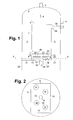
Figur 2- einen Querschnitt in der Ebene
A-A der Figur 1, Figuren 3 und 4- eine zweite Ausführungsform eines erfindungsgemäßen Rücklaufkondensator in Längs- beziehungsweise Querschnitt,
Figuren 5 und 6- eine dritte Ausführungsform eines erfindungsgemäßen Rücklaufkondensator in Längs- beziehungsweise Querschnitt und
Figur 7- Wärmetauscherblöcke mit weiteren Header-Formen.
- FIG. 1
- a longitudinal section through a retrace capacitor in a first embodiment of the invention,
- FIG. 2
- a cross section in the plane AA of Figure 1,
- FIGS. 3 and 4
- a second embodiment of a reflux condenser according to the invention in longitudinal or cross-section,
- FIGS. 5 and 6
- a third embodiment of a reflux condenser according to the invention in longitudinal or cross-section and
- FIG. 7
- Heat exchanger blocks with other header shapes.
Ein Wärmetauscherblock 1 ist im Inneren eines Druckbehälters 2 angeordnet. Er ist als gelöteter Aluminium-Plattenwärmetauscher ausgebildet und weist abwechselnd Rücklaufpassagen und Kältemittelpassagen auf, die nicht im Einzelnen dargestellt sind.A
Die Kältemittelpassagen funktionieren bei dem Ausführungsbeispiel als Umlaufverdampfer. Ein flüssiges Kältemittel wird über einen Stutzen 4 in den Zwischenraum 3 zwischen Druckbehälter 3 und Wärmetauscherblock 1 eingeführt und bildet dort ein Flüssigkeitsbad. Über seitliche Öffnungen der Kältemittelpassagen strömt Flüssigkeit 5 aus dem Bad in die Kältemittelpassagen ein. Durch den Thermosiphon-Effekt wird ein Zwei-Phasen-Gemisch in den Kältemittelpassagen nach oben geführt und tritt an der Oberseite des Wärmetauscherblocks 1 aus den dort offenen Kältemittelpassagen aus. Gasförmiges Kältemittel 6 wird über eine Gasleitung 7 abgezogen, flüssig verbliebenes Kältemittel 8 fällt in das Flüssigkeitsbad zurück.The refrigerant passages function as a circulation evaporator in the embodiment. A liquid refrigerant is introduced via a
Die Rücklaufpassagen sind an ihrem unteren Ende offen und kommunizieren mit einem Header, der unterhalb des Wärmetauscherblocks 1 angeordnet ist. Der Header weist vier rechteckige Seitenwände 9, 10, 11, 12 und einen Boden 13 auf. Die Grundfläche des Bodens 13 bildet den Boden einer Phasentrenneinrichtung und weist in dem Beispiel vier Gasdurchtrittsöffnungen 14, 15, 16, 17 auf. Die Gasdurchtrittsöffnungen sind an ihrer Oberseite mit je einer Umrandung 18 zum Aufstauen von Flüssigkeit versehen. Sie verhindern insbesondere, dass auf dem Boden aufgestaute Flüssigkeit in die Gasdurchtrittsöffnung gelangt. Über ein Ablaufrohr 19 kann die aufgestaute Flüssigkeit abfließen. Oberhalb der Gasdurchtrittsöffnungen ist jeweils eine Abdeckung 20, 21 angeordnet. Die Grundfläche des Bodens 13 stellt den zentralen Bereich einer Bodenplatte dar, deren peripherer Bereich 31 den zentralen Bereich umschließt und den Druckbehälter 2 nach unten abschließt.The return passages are open at their lower end and communicate with a header disposed below the
Der Rücklaufkondensator ist unmittelbar auf dem Kopf einer Trennkolonne angeordnet. Die Kolonnenwand 22 ist in Figur 1 durch gestrichelte Linien angedeutet. Dampf 23 aus dem Kolonnenkopf strömt über die Gasdurchtrittsöffnungen, wird von den Abdeckungen 20, 21 umgelenkt (24) und strömt schließlich in die Rücklaufpassagen ein (25). In den Rücklaufpassagen gebildete Flüssigkeit (26) tritt aus deren unterem Ende aus, trifft gegebenenfalls auf eine der Abdeckungen 20, 21, wird auf dem Boden 13 aufgestaut und fließt schließlich über das Ablaufrohr 19 ab (27, 28). Der gasförmig verbliebene Anteil wird oben über einen oder mehrere seitliche Header 29 und ein Gasabführrohr 30 aus den Rücklaufpassagen abgezogen. Abweichend von der Darstellung in der Zeichnung können am oberen Ende auch zwei oder mehr Header zum Abführen des gasförmig verbliebenen Anteils angeordnet sein.
In der Ausführungsform der Figuren 3 und 4 weist der Rücklaufkondensator zwei Wärmetauscherblöcke 101, 201 auf. Die Bauteile, die denjenigen der Figur 1 entsprechen sind auch mit entsprechenden Bezugszeichen (gegebenenfalls plus 100 beziehungsweise plus 200) versehen. Einige Einzelheiten wie der Deckel des Druckbehälters 2, die Abdeckungen (20, 21 in Figur 1) der Gasdurchtrittsöffnungen 114, 214 oder die Ablaufrohre (19 in Figur 1) sind nicht dargestellt.The reflux condenser is arranged directly on top of a separation column. The
In the embodiment of FIGS. 3 and 4, the reflux condenser has two heat exchanger blocks 101, 201. The components which correspond to those of Figure 1 are also provided with corresponding reference numerals (optionally plus 100 or plus 200). Some details such as the lid of the
Die Böden 113, 213 der als Phasentrenneinrichtung ausgebildeten Header sind hier nicht eben wie in Figur 1, sondern gewölbt ausgeführt. Der Druckbehälter 2 wird in dieser Ausführungsform mittels einer ebenfalls gewölbten unteren Abdeckung 131 nach unten abgeschlossen, die unabhängig von den Böden 113, 213 der Phasentrenneinrichtung ist. Dies ist hier erforderlich, weil die beiden Wärmetauscherblöcke 101, 210 einen Querschnitt aufweisen, der über den Querschnitt des darunter angeordneten Behälters 122, beispielsweise einer Trennkolonne, hinausragt.The
Das Ausführungsbeispiel der Figuren 5 und 6 unterscheidet sich hiervon darin, dass der Rücklaufkondensator einen einzigen Wärmetauscherblock aufweist. Ansonsten gilt das oben Gesagte analog.The embodiment of Figures 5 and 6 differs from this in that the return condenser has a single heat exchanger block. Otherwise, the above applies analogously.
Claims (13)
Priority Applications (2)
| Application Number | Priority Date | Filing Date | Title |
|---|---|---|---|
| EP07013228.7A EP1890100B1 (en) | 2006-08-08 | 2007-07-06 | Dephlegmator |
| PL07013228T PL1890100T3 (en) | 2006-08-08 | 2007-07-06 | Dephlegmator |
Applications Claiming Priority (3)
| Application Number | Priority Date | Filing Date | Title |
|---|---|---|---|
| DE102006037058 | 2006-08-08 | ||
| EP06023934A EP1890099A1 (en) | 2006-08-08 | 2006-11-17 | Dephlegmator |
| EP07013228.7A EP1890100B1 (en) | 2006-08-08 | 2007-07-06 | Dephlegmator |
Publications (3)
| Publication Number | Publication Date |
|---|---|
| EP1890100A2 true EP1890100A2 (en) | 2008-02-20 |
| EP1890100A3 EP1890100A3 (en) | 2012-05-23 |
| EP1890100B1 EP1890100B1 (en) | 2018-06-13 |
Family
ID=38668793
Family Applications (1)
| Application Number | Title | Priority Date | Filing Date |
|---|---|---|---|
| EP07013228.7A Active EP1890100B1 (en) | 2006-08-08 | 2007-07-06 | Dephlegmator |
Country Status (2)
| Country | Link |
|---|---|
| EP (1) | EP1890100B1 (en) |
| PL (1) | PL1890100T3 (en) |
Cited By (2)
| Publication number | Priority date | Publication date | Assignee | Title |
|---|---|---|---|---|
| FR2929384A1 (en) * | 2008-03-27 | 2009-10-02 | Air Liquide | Air separating apparatus, has distillation column comprising head condenser with dephlegmator whose horizontal section covers seventy percentage of section of column, and extracting unit extracting nitrogen enriched product in column head |
| DE102008045736A1 (en) | 2008-09-04 | 2010-03-11 | Linde Ag | Return flow condenser has heat exchanger block, return passage and refrigerant passage, where upper and lateral sides of pressure reservoir are enclosed by heat exchanger block |
Citations (6)
| Publication number | Priority date | Publication date | Assignee | Title |
|---|---|---|---|---|
| US3720071A (en) * | 1969-06-14 | 1973-03-13 | Linde Ag | Heat exchanger |
| US4124069A (en) * | 1975-08-01 | 1978-11-07 | Linde Aktiengesellschaft | Heat exchanger with spirally wound sheets |
| FR2431103A1 (en) * | 1978-07-12 | 1980-02-08 | Air Liquide | Low-temp. fractionation column for sepg. gaseous mixt. - superposed compartments interconnected by vaporiser-condenser circumscribed by column ensuring max. compactness |
| US5730002A (en) * | 1995-10-11 | 1998-03-24 | Institut Francais Du Petrole | Process and device for fractionating a fluid containing several separable constituents, such as a natural gas |
| FR2798599A1 (en) * | 1999-09-21 | 2001-03-23 | Air Liquide | THERMOSIPHON VAPORIZER-CONDENSER AND CORRESPONDING AIR DISTILLATION SYSTEM |
| US6349566B1 (en) * | 2000-09-15 | 2002-02-26 | Air Products And Chemicals, Inc. | Dephlegmator system and process |
-
2007
- 2007-07-06 PL PL07013228T patent/PL1890100T3/en unknown
- 2007-07-06 EP EP07013228.7A patent/EP1890100B1/en active Active
Patent Citations (6)
| Publication number | Priority date | Publication date | Assignee | Title |
|---|---|---|---|---|
| US3720071A (en) * | 1969-06-14 | 1973-03-13 | Linde Ag | Heat exchanger |
| US4124069A (en) * | 1975-08-01 | 1978-11-07 | Linde Aktiengesellschaft | Heat exchanger with spirally wound sheets |
| FR2431103A1 (en) * | 1978-07-12 | 1980-02-08 | Air Liquide | Low-temp. fractionation column for sepg. gaseous mixt. - superposed compartments interconnected by vaporiser-condenser circumscribed by column ensuring max. compactness |
| US5730002A (en) * | 1995-10-11 | 1998-03-24 | Institut Francais Du Petrole | Process and device for fractionating a fluid containing several separable constituents, such as a natural gas |
| FR2798599A1 (en) * | 1999-09-21 | 2001-03-23 | Air Liquide | THERMOSIPHON VAPORIZER-CONDENSER AND CORRESPONDING AIR DISTILLATION SYSTEM |
| US6349566B1 (en) * | 2000-09-15 | 2002-02-26 | Air Products And Chemicals, Inc. | Dephlegmator system and process |
Cited By (2)
| Publication number | Priority date | Publication date | Assignee | Title |
|---|---|---|---|---|
| FR2929384A1 (en) * | 2008-03-27 | 2009-10-02 | Air Liquide | Air separating apparatus, has distillation column comprising head condenser with dephlegmator whose horizontal section covers seventy percentage of section of column, and extracting unit extracting nitrogen enriched product in column head |
| DE102008045736A1 (en) | 2008-09-04 | 2010-03-11 | Linde Ag | Return flow condenser has heat exchanger block, return passage and refrigerant passage, where upper and lateral sides of pressure reservoir are enclosed by heat exchanger block |
Also Published As
| Publication number | Publication date |
|---|---|
| EP1890100B1 (en) | 2018-06-13 |
| PL1890100T3 (en) | 2018-11-30 |
| EP1890100A3 (en) | 2012-05-23 |
Similar Documents
| Publication | Publication Date | Title |
|---|---|---|
| DE69209994T2 (en) | Indirect plate heat exchanger | |
| DE2943687C2 (en) | Trough-like device for collecting and distributing the liquid for a countercurrent column | |
| DE59310250T2 (en) | Plate heat exchanger | |
| DE60303197T2 (en) | HEAT EXCHANGE RUBBER AND MANUFACTURING METHOD THEREFOR | |
| EP1890099A1 (en) | Dephlegmator | |
| EP2859295B1 (en) | Heat exchanger | |
| DE1053469B (en) | Fractionating column | |
| EP3129738B1 (en) | Liquid distributor and arrangement | |
| DE2222269C2 (en) | Falling column for rectifying liquids | |
| EP1704906B1 (en) | Mass transfer column with transfer trays | |
| EP0795349A1 (en) | Device and process for evaporating a liquid | |
| EP1477761B1 (en) | Plate heat exchanger | |
| EP1890100B1 (en) | Dephlegmator | |
| DE102005059917A1 (en) | Evaporator | |
| DE69605347T2 (en) | Heat exchangers with soldered plates | |
| EP3159648B1 (en) | Plate heat exchanger capacitor evaporator and method for cryogenic decomposition of air | |
| DE10230325A1 (en) | tray column | |
| DE19716836A1 (en) | Heat exchanger for air conditioner recirculation circuit | |
| EP3077750B1 (en) | Heat exchanger with collection channelfor the extraction of a liquid phase | |
| WO2006111379A1 (en) | Filter plate that can be cooled and heated | |
| DE102004059680B4 (en) | Construction arrangement for means for exchanging heat | |
| EP0517670B1 (en) | Supporting grid for packing inside mass transfer columns | |
| DE102007007582A1 (en) | Gas-liquid-distributor for feeding a two-phase gas-liquid-feed in substance exchange column and for separate distribution of gas and liquid in the column, comprises a distributor channel having gas outlets and outlet shaft for liquid | |
| DE4017229C2 (en) | ||
| DE102017106638B4 (en) | Filter dryer for a heat pump of a household appliance such as a tumble dryer, dishwasher or washer dryer |
Legal Events
| Date | Code | Title | Description |
|---|---|---|---|
| PUAI | Public reference made under article 153(3) epc to a published international application that has entered the european phase |
Free format text: ORIGINAL CODE: 0009012 |
|
| AK | Designated contracting states |
Kind code of ref document: A2 Designated state(s): AT BE BG CH CY CZ DE DK EE ES FI FR GB GR HU IE IS IT LI LT LU LV MC MT NL PL PT RO SE SI SK TR |
|
| AX | Request for extension of the european patent |
Extension state: AL BA HR MK YU |
|
| RAP1 | Party data changed (applicant data changed or rights of an application transferred) |
Owner name: LINDE AG |
|
| REG | Reference to a national code |
Ref country code: DE Ref legal event code: R079 Ref document number: 502007016222 Country of ref document: DE Free format text: PREVIOUS MAIN CLASS: F25J0003000000 Ipc: F25J0003040000 |
|
| PUAL | Search report despatched |
Free format text: ORIGINAL CODE: 0009013 |
|
| AK | Designated contracting states |
Kind code of ref document: A3 Designated state(s): AT BE BG CH CY CZ DE DK EE ES FI FR GB GR HU IE IS IT LI LT LU LV MC MT NL PL PT RO SE SI SK TR |
|
| AX | Request for extension of the european patent |
Extension state: AL BA HR MK RS |
|
| RIC1 | Information provided on ipc code assigned before grant |
Ipc: F25J 3/00 20060101ALI20120418BHEP Ipc: F28B 9/00 20060101ALI20120418BHEP Ipc: F28D 9/00 20060101ALI20120418BHEP Ipc: B01D 5/00 20060101ALI20120418BHEP Ipc: F25J 3/04 20060101AFI20120418BHEP |
|
| 17P | Request for examination filed |
Effective date: 20121025 |
|
| AKX | Designation fees paid |
Designated state(s): AT BE BG CH CY CZ DE DK EE ES FI FR GB GR HU IE IS IT LI LT LU LV MC MT NL PL PT RO SE SI SK TR |
|
| 17Q | First examination report despatched |
Effective date: 20160122 |
|
| GRAP | Despatch of communication of intention to grant a patent |
Free format text: ORIGINAL CODE: EPIDOSNIGR1 |
|
| INTG | Intention to grant announced |
Effective date: 20171120 |
|
| GRAJ | Information related to disapproval of communication of intention to grant by the applicant or resumption of examination proceedings by the epo deleted |
Free format text: ORIGINAL CODE: EPIDOSDIGR1 |
|
| GRAL | Information related to payment of fee for publishing/printing deleted |
Free format text: ORIGINAL CODE: EPIDOSDIGR3 |
|
| GRAS | Grant fee paid |
Free format text: ORIGINAL CODE: EPIDOSNIGR3 |
|
| INTC | Intention to grant announced (deleted) | ||
| GRAP | Despatch of communication of intention to grant a patent |
Free format text: ORIGINAL CODE: EPIDOSNIGR1 |
|
| GRAA | (expected) grant |
Free format text: ORIGINAL CODE: 0009210 |
|
| INTG | Intention to grant announced |
Effective date: 20180503 |
|
| REG | Reference to a national code |
Ref country code: FR Ref legal event code: PLFP Year of fee payment: 12 |
|
| AK | Designated contracting states |
Kind code of ref document: B1 Designated state(s): AT BE BG CH CY CZ DE DK EE ES FI FR GB GR HU IE IS IT LI LT LU LV MC MT NL PL PT RO SE SI SK TR |
|
| REG | Reference to a national code |
Ref country code: GB Ref legal event code: FG4D Free format text: NOT ENGLISH |
|
| REG | Reference to a national code |
Ref country code: CH Ref legal event code: EP Ref country code: AT Ref legal event code: REF Ref document number: 1008922 Country of ref document: AT Kind code of ref document: T Effective date: 20180615 |
|
| REG | Reference to a national code |
Ref country code: IE Ref legal event code: FG4D Free format text: LANGUAGE OF EP DOCUMENT: GERMAN |
|
| REG | Reference to a national code |
Ref country code: DE Ref legal event code: R096 Ref document number: 502007016222 Country of ref document: DE |
|
| REG | Reference to a national code |
Ref country code: EE Ref legal event code: FG4A Ref document number: 015832 Country of ref document: EE Effective date: 20180731 |
|
| REG | Reference to a national code |
Ref country code: NL Ref legal event code: MP Effective date: 20180613 |
|
| PG25 | Lapsed in a contracting state [announced via postgrant information from national office to epo] |
Ref country code: SE Free format text: LAPSE BECAUSE OF FAILURE TO SUBMIT A TRANSLATION OF THE DESCRIPTION OR TO PAY THE FEE WITHIN THE PRESCRIBED TIME-LIMIT Effective date: 20180613 Ref country code: BG Free format text: LAPSE BECAUSE OF FAILURE TO SUBMIT A TRANSLATION OF THE DESCRIPTION OR TO PAY THE FEE WITHIN THE PRESCRIBED TIME-LIMIT Effective date: 20180913 Ref country code: CY Free format text: LAPSE BECAUSE OF FAILURE TO SUBMIT A TRANSLATION OF THE DESCRIPTION OR TO PAY THE FEE WITHIN THE PRESCRIBED TIME-LIMIT Effective date: 20180613 Ref country code: FI Free format text: LAPSE BECAUSE OF FAILURE TO SUBMIT A TRANSLATION OF THE DESCRIPTION OR TO PAY THE FEE WITHIN THE PRESCRIBED TIME-LIMIT Effective date: 20180613 Ref country code: ES Free format text: LAPSE BECAUSE OF FAILURE TO SUBMIT A TRANSLATION OF THE DESCRIPTION OR TO PAY THE FEE WITHIN THE PRESCRIBED TIME-LIMIT Effective date: 20180613 |
|
| REG | Reference to a national code |
Ref country code: SK Ref legal event code: T3 Ref document number: E 28038 Country of ref document: SK |
|
| PG25 | Lapsed in a contracting state [announced via postgrant information from national office to epo] |
Ref country code: GR Free format text: LAPSE BECAUSE OF FAILURE TO SUBMIT A TRANSLATION OF THE DESCRIPTION OR TO PAY THE FEE WITHIN THE PRESCRIBED TIME-LIMIT Effective date: 20180914 |
|
| PG25 | Lapsed in a contracting state [announced via postgrant information from national office to epo] |
Ref country code: NL Free format text: LAPSE BECAUSE OF FAILURE TO SUBMIT A TRANSLATION OF THE DESCRIPTION OR TO PAY THE FEE WITHIN THE PRESCRIBED TIME-LIMIT Effective date: 20180613 |
|
| PG25 | Lapsed in a contracting state [announced via postgrant information from national office to epo] |
Ref country code: RO Free format text: LAPSE BECAUSE OF FAILURE TO SUBMIT A TRANSLATION OF THE DESCRIPTION OR TO PAY THE FEE WITHIN THE PRESCRIBED TIME-LIMIT Effective date: 20180613 Ref country code: IS Free format text: LAPSE BECAUSE OF FAILURE TO SUBMIT A TRANSLATION OF THE DESCRIPTION OR TO PAY THE FEE WITHIN THE PRESCRIBED TIME-LIMIT Effective date: 20181013 |
|
| PG25 | Lapsed in a contracting state [announced via postgrant information from national office to epo] |
Ref country code: IT Free format text: LAPSE BECAUSE OF FAILURE TO SUBMIT A TRANSLATION OF THE DESCRIPTION OR TO PAY THE FEE WITHIN THE PRESCRIBED TIME-LIMIT Effective date: 20180613 |
|
| REG | Reference to a national code |
Ref country code: CH Ref legal event code: PL Ref country code: HU Ref legal event code: AG4A Ref document number: E040267 Country of ref document: HU |
|
| REG | Reference to a national code |
Ref country code: DE Ref legal event code: R097 Ref document number: 502007016222 Country of ref document: DE |
|
| PG25 | Lapsed in a contracting state [announced via postgrant information from national office to epo] |
Ref country code: MC Free format text: LAPSE BECAUSE OF FAILURE TO SUBMIT A TRANSLATION OF THE DESCRIPTION OR TO PAY THE FEE WITHIN THE PRESCRIBED TIME-LIMIT Effective date: 20180613 Ref country code: LU Free format text: LAPSE BECAUSE OF NON-PAYMENT OF DUE FEES Effective date: 20180706 |
|
| REG | Reference to a national code |
Ref country code: BE Ref legal event code: MM Effective date: 20180731 |
|
| REG | Reference to a national code |
Ref country code: IE Ref legal event code: MM4A |
|
| PLBE | No opposition filed within time limit |
Free format text: ORIGINAL CODE: 0009261 |
|
| STAA | Information on the status of an ep patent application or granted ep patent |
Free format text: STATUS: NO OPPOSITION FILED WITHIN TIME LIMIT |
|
| PG25 | Lapsed in a contracting state [announced via postgrant information from national office to epo] |
Ref country code: CH Free format text: LAPSE BECAUSE OF NON-PAYMENT OF DUE FEES Effective date: 20180731 Ref country code: LI Free format text: LAPSE BECAUSE OF NON-PAYMENT OF DUE FEES Effective date: 20180731 Ref country code: IE Free format text: LAPSE BECAUSE OF NON-PAYMENT OF DUE FEES Effective date: 20180706 |
|
| 26N | No opposition filed |
Effective date: 20190314 |
|
| GBPC | Gb: european patent ceased through non-payment of renewal fee |
Effective date: 20180913 |
|
| PG25 | Lapsed in a contracting state [announced via postgrant information from national office to epo] |
Ref country code: BE Free format text: LAPSE BECAUSE OF NON-PAYMENT OF DUE FEES Effective date: 20180731 Ref country code: SI Free format text: LAPSE BECAUSE OF FAILURE TO SUBMIT A TRANSLATION OF THE DESCRIPTION OR TO PAY THE FEE WITHIN THE PRESCRIBED TIME-LIMIT Effective date: 20180613 Ref country code: DK Free format text: LAPSE BECAUSE OF FAILURE TO SUBMIT A TRANSLATION OF THE DESCRIPTION OR TO PAY THE FEE WITHIN THE PRESCRIBED TIME-LIMIT Effective date: 20180613 |
|
| REG | Reference to a national code |
Ref country code: AT Ref legal event code: MM01 Ref document number: 1008922 Country of ref document: AT Kind code of ref document: T Effective date: 20180706 |
|
| PG25 | Lapsed in a contracting state [announced via postgrant information from national office to epo] |
Ref country code: GB Free format text: LAPSE BECAUSE OF NON-PAYMENT OF DUE FEES Effective date: 20180913 |
|
| PG25 | Lapsed in a contracting state [announced via postgrant information from national office to epo] |
Ref country code: AT Free format text: LAPSE BECAUSE OF NON-PAYMENT OF DUE FEES Effective date: 20180706 |
|
| PG25 | Lapsed in a contracting state [announced via postgrant information from national office to epo] |
Ref country code: MT Free format text: LAPSE BECAUSE OF FAILURE TO SUBMIT A TRANSLATION OF THE DESCRIPTION OR TO PAY THE FEE WITHIN THE PRESCRIBED TIME-LIMIT Effective date: 20180613 |
|
| PG25 | Lapsed in a contracting state [announced via postgrant information from national office to epo] |
Ref country code: TR Free format text: LAPSE BECAUSE OF FAILURE TO SUBMIT A TRANSLATION OF THE DESCRIPTION OR TO PAY THE FEE WITHIN THE PRESCRIBED TIME-LIMIT Effective date: 20180613 |
|
| PG25 | Lapsed in a contracting state [announced via postgrant information from national office to epo] |
Ref country code: PT Free format text: LAPSE BECAUSE OF FAILURE TO SUBMIT A TRANSLATION OF THE DESCRIPTION OR TO PAY THE FEE WITHIN THE PRESCRIBED TIME-LIMIT Effective date: 20180613 |
|
| REG | Reference to a national code |
Ref country code: DE Ref legal event code: R081 Ref document number: 502007016222 Country of ref document: DE Owner name: LINDE GMBH, DE Free format text: FORMER OWNER: LINDE AG, 80331 MUENCHEN, DE |
|
| PGFP | Annual fee paid to national office [announced via postgrant information from national office to epo] |
Ref country code: EE Payment date: 20230718 Year of fee payment: 17 |
|
| PGFP | Annual fee paid to national office [announced via postgrant information from national office to epo] |
Ref country code: HU Payment date: 20230629 Year of fee payment: 17 Ref country code: FR Payment date: 20230724 Year of fee payment: 17 Ref country code: DE Payment date: 20230720 Year of fee payment: 17 |
|
| PGFP | Annual fee paid to national office [announced via postgrant information from national office to epo] |
Ref country code: LV Payment date: 20230719 Year of fee payment: 17 |
|
| PGFP | Annual fee paid to national office [announced via postgrant information from national office to epo] |
Ref country code: LT Payment date: 20240620 Year of fee payment: 18 |
|
| PGFP | Annual fee paid to national office [announced via postgrant information from national office to epo] |
Ref country code: CZ Payment date: 20240621 Year of fee payment: 18 |
|
| PGFP | Annual fee paid to national office [announced via postgrant information from national office to epo] |
Ref country code: SK Payment date: 20240701 Year of fee payment: 18 |
|
| PGFP | Annual fee paid to national office [announced via postgrant information from national office to epo] |
Ref country code: PL Payment date: 20240621 Year of fee payment: 18 |