EP1890036A2 - Displacement control valve for variable displacement compressor - Google Patents
Displacement control valve for variable displacement compressor Download PDFInfo
- Publication number
- EP1890036A2 EP1890036A2 EP07114092A EP07114092A EP1890036A2 EP 1890036 A2 EP1890036 A2 EP 1890036A2 EP 07114092 A EP07114092 A EP 07114092A EP 07114092 A EP07114092 A EP 07114092A EP 1890036 A2 EP1890036 A2 EP 1890036A2
- Authority
- EP
- European Patent Office
- Prior art keywords
- valve
- valve body
- connecting portion
- chamber
- pressure
- Prior art date
- Legal status (The legal status is an assumption and is not a legal conclusion. Google has not performed a legal analysis and makes no representation as to the accuracy of the status listed.)
- Withdrawn
Links
Images




Classifications
-
- F—MECHANICAL ENGINEERING; LIGHTING; HEATING; WEAPONS; BLASTING
- F04—POSITIVE - DISPLACEMENT MACHINES FOR LIQUIDS; PUMPS FOR LIQUIDS OR ELASTIC FLUIDS
- F04B—POSITIVE-DISPLACEMENT MACHINES FOR LIQUIDS; PUMPS
- F04B27/00—Multi-cylinder pumps specially adapted for elastic fluids and characterised by number or arrangement of cylinders
- F04B27/08—Multi-cylinder pumps specially adapted for elastic fluids and characterised by number or arrangement of cylinders having cylinders coaxial with, or parallel or inclined to, main shaft axis
- F04B27/14—Control
- F04B27/16—Control of pumps with stationary cylinders
- F04B27/18—Control of pumps with stationary cylinders by varying the relative positions of a swash plate and a cylinder block
- F04B27/1804—Controlled by crankcase pressure
-
- F—MECHANICAL ENGINEERING; LIGHTING; HEATING; WEAPONS; BLASTING
- F04—POSITIVE - DISPLACEMENT MACHINES FOR LIQUIDS; PUMPS FOR LIQUIDS OR ELASTIC FLUIDS
- F04B—POSITIVE-DISPLACEMENT MACHINES FOR LIQUIDS; PUMPS
- F04B27/00—Multi-cylinder pumps specially adapted for elastic fluids and characterised by number or arrangement of cylinders
- F04B27/08—Multi-cylinder pumps specially adapted for elastic fluids and characterised by number or arrangement of cylinders having cylinders coaxial with, or parallel or inclined to, main shaft axis
- F04B27/14—Control
- F04B27/16—Control of pumps with stationary cylinders
- F04B27/18—Control of pumps with stationary cylinders by varying the relative positions of a swash plate and a cylinder block
- F04B27/1804—Controlled by crankcase pressure
- F04B2027/1809—Controlled pressure
- F04B2027/1813—Crankcase pressure
-
- F—MECHANICAL ENGINEERING; LIGHTING; HEATING; WEAPONS; BLASTING
- F04—POSITIVE - DISPLACEMENT MACHINES FOR LIQUIDS; PUMPS FOR LIQUIDS OR ELASTIC FLUIDS
- F04B—POSITIVE-DISPLACEMENT MACHINES FOR LIQUIDS; PUMPS
- F04B27/00—Multi-cylinder pumps specially adapted for elastic fluids and characterised by number or arrangement of cylinders
- F04B27/08—Multi-cylinder pumps specially adapted for elastic fluids and characterised by number or arrangement of cylinders having cylinders coaxial with, or parallel or inclined to, main shaft axis
- F04B27/14—Control
- F04B27/16—Control of pumps with stationary cylinders
- F04B27/18—Control of pumps with stationary cylinders by varying the relative positions of a swash plate and a cylinder block
- F04B27/1804—Controlled by crankcase pressure
- F04B2027/1822—Valve-controlled fluid connection
- F04B2027/1827—Valve-controlled fluid connection between crankcase and discharge chamber
-
- F—MECHANICAL ENGINEERING; LIGHTING; HEATING; WEAPONS; BLASTING
- F04—POSITIVE - DISPLACEMENT MACHINES FOR LIQUIDS; PUMPS FOR LIQUIDS OR ELASTIC FLUIDS
- F04B—POSITIVE-DISPLACEMENT MACHINES FOR LIQUIDS; PUMPS
- F04B27/00—Multi-cylinder pumps specially adapted for elastic fluids and characterised by number or arrangement of cylinders
- F04B27/08—Multi-cylinder pumps specially adapted for elastic fluids and characterised by number or arrangement of cylinders having cylinders coaxial with, or parallel or inclined to, main shaft axis
- F04B27/14—Control
- F04B27/16—Control of pumps with stationary cylinders
- F04B27/18—Control of pumps with stationary cylinders by varying the relative positions of a swash plate and a cylinder block
- F04B27/1804—Controlled by crankcase pressure
- F04B2027/184—Valve controlling parameter
- F04B2027/185—Discharge pressure
-
- F—MECHANICAL ENGINEERING; LIGHTING; HEATING; WEAPONS; BLASTING
- F04—POSITIVE - DISPLACEMENT MACHINES FOR LIQUIDS; PUMPS FOR LIQUIDS OR ELASTIC FLUIDS
- F04B—POSITIVE-DISPLACEMENT MACHINES FOR LIQUIDS; PUMPS
- F04B27/00—Multi-cylinder pumps specially adapted for elastic fluids and characterised by number or arrangement of cylinders
- F04B27/08—Multi-cylinder pumps specially adapted for elastic fluids and characterised by number or arrangement of cylinders having cylinders coaxial with, or parallel or inclined to, main shaft axis
- F04B27/14—Control
- F04B27/16—Control of pumps with stationary cylinders
- F04B27/18—Control of pumps with stationary cylinders by varying the relative positions of a swash plate and a cylinder block
- F04B27/1804—Controlled by crankcase pressure
- F04B2027/184—Valve controlling parameter
- F04B2027/1854—External parameters
-
- F—MECHANICAL ENGINEERING; LIGHTING; HEATING; WEAPONS; BLASTING
- F04—POSITIVE - DISPLACEMENT MACHINES FOR LIQUIDS; PUMPS FOR LIQUIDS OR ELASTIC FLUIDS
- F04B—POSITIVE-DISPLACEMENT MACHINES FOR LIQUIDS; PUMPS
- F04B2205/00—Fluid parameters
- F04B2205/05—Pressure after the pump outlet
-
- F—MECHANICAL ENGINEERING; LIGHTING; HEATING; WEAPONS; BLASTING
- F04—POSITIVE - DISPLACEMENT MACHINES FOR LIQUIDS; PUMPS FOR LIQUIDS OR ELASTIC FLUIDS
- F04B—POSITIVE-DISPLACEMENT MACHINES FOR LIQUIDS; PUMPS
- F04B2205/00—Fluid parameters
- F04B2205/08—Pressure difference over a throttle
Definitions
- the present invention relates to a displacement control valve of a variable displacement compressor which is used in a vehicle air conditioner.
- a variable displacement compressor (hereinafter referred to as "compressor") is known as a compressor for use in a vehicle air conditioner, which variably controls the displacement.
- compressor a swash plate is accommodated in a crank chamber and is inclinable with respect to a drive shaft.
- the inclination of the swash plate approaches to be perpendicular to the axis of the drive shaft (the inclination angle of the swash plate decreases).
- the swash plate is inclined so that the inclination of the swash plate approaches to the axis of the drive shaft (the inclination angle of the swash plate increases).
- the compressor has a plurarity of pistons , and the stroke of the pistons changes in accordance with the inclination angle of the swash plate. For example, when the pressure in the crank chamber is high and the inclination angle of the swash plate is small, the stroke of the piston is short. When the pressure in the crank chamber is low and the inclination angle of the swash plate is large, the stroke of the pistons is long. As the stroke of the pistons decreases, the displacement of the compressor decreases. As the stroke of the pistons increases, the displacement of the compressor increases.
- Japanese Unexamined Patent Application Publication (KOKAI) No. 9-268973 or, the corresponding U.S. Patent No. 5890876 discloses a displacement control valve 49 for a compressor.
- the displacement control valve 49 has a valve housing 61 and a solenoid 62 joined thereto.
- a valve chamber 63 is defined by the valve housing 61 and the solenoid 62, and is connected to a discharge chamber 38.
- a valve body 64 is arranged in the valve chamber 63 to open and close a valve hole 66.
- the valve hole 66 is connected to a crank chamber 15.
- the displacement control valve 49 has a pressure sensing chamber 68 which is connected to a suction passage 32 and provided a bellows 70 therein.
- the bellows 70 is connected to the valve body 64 by a rod 72 which has a large diameter portion 72a and a small diameter portion 72b.
- the large-diameter portion 72a extends through and slides with respect to a guide hole 71.
- the small-diameter portion 72b extends through the valve hole 66.
- the small-diameter portion 72b is connected to a top end 64a of the valve body 64 by a tapered portion 73. The diameter of the tapered portion 73 increases toward the valve body 64.
- valve hole 66 When the valve hole 66 is opened, the refrigerant gas in the discharge chamber 38 flows into the crank chamber 15. When the valve hole 66 is closed by the valve body 64, the refrigerant is not introduced from the discharge chamber 38 to the crank chamber 15.
- the tapered portion 73 is formed at the top end 64a of the valve body 64, and the diameter of the tapered portion 73 adjacent to the top end 64a is larger than the diameter of the tapered portion 73 adjacent to the rod 72, the cross-sectional area of the flow path of the valve hole 66 varies gradually in accordance with the movement of the tapered portion 73, when the valve body 64 opens and closes the valve hole 66.
- the displacement control valve 49 due to opening and closing of the displacement control valve 49, rapid start and stop of the supply of the highly-pressurized refrigerant into the crank chamber 15 may be prevented.
- the cross-sectional area of the flow path through which the refrigerant flows varies discontinuously at a connecting part of the tapered portion 73 and the top end 64a of the valve body 64, and a continuous flow rate control and the stable control may not be accomplished.
- the movement distance of the valve body 64 is indicated by a horizontal axis
- the cross-sectional area in the flow path is indicated by a vertical axis.
- a characteristic of the conventional art is shown by a characteristic curve indicated by a graph G0, which connects points A, B, C, and D.
- the characteristic curve G0 is discontinuous at the point B and C.
- the cross-sectional area of the flow path varies discontinuously in accordance with the movement distance of the valve body 64.
- the graph G0 varies discontinuously.
- the point B corresponds to the discontinuous connecting part of the top end 64a of the valve body 64 and the larger-diameter side of the tapered portion 73.
- the point C corresponds to the discontinuous connecting part of the small-diameter portion 72b of the tapered portion 73 and the smaller-diameter side of the pressure sensing rod 72.
- the present invention which is made in view of the above problems is directed to a displacement control valve for a variable displacement compressor which has a continuous flow rate control and an improved stability in control.
- An aspect in accordance with the present invention provides a displacement control valve for a variable displacement compressor.
- the displacement control valve has a control passage, a valve hole formed in the control passage, a first shaft portion including a valve body, and a connecting portion connected to the end portion of the valve body.
- the control passage is connected to a crank chamber for controlling the pressure in the crank chamber for adjusting the discharge displacement of the compressor.
- the valve body is formed at an end portion of the first shaft portion to open and close the valve hole.
- the connecting portion connected to the end portion of the valve body is disposed into the valve hole, and a circumferential surface of the connecting portion has a curved surface so as to be flared out at an end of the connecting portion.
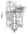
- a variable displacement compressor 10 (hereinafter referred to as "compressor") includes a housing, which forms its configuration.
- the housing 11 includes a cylinder block 12 having a plurarity of cylinder bores 12a formed therein, a front housing 13 which is joined to the front end (left side in FIG. 1) of the cylinder block 12, and a rear housing 14 which is joined to the rear end (right side in FIG. 1) of the cylinder block 12.
- a bolt 15 is passed through the front housing 13, the cylinder block 12 and the rear housing 14 to tighten those components in the axial direction of the bolt 15, so that those components are integrally fixed to form the housing 11.
- the front housing 13 has a crank chamber 16 defined therein, whose rear end is closed by the cylinder block 12.
- a drive shaft 17 is rotatably supported by a radial bearing 18 provided in the front housing 13 and a radial bearing 19 provided in the cylinder block 12 so as to extend through the vicinity of the center of the crank chamber 16.
- a sealing mechanism 20 is provided in front of the radial bearing 18 which supports the front part of the drive shaft 17 so as to keep in slide contact with the circumferential surface of the drive shaft 17.
- the sealing mechanism 20 has a lip seal member and the like to prevent refrigerant in the crank chamber 16 from leaking through a clearance between the front housing 13 and the drive shaft 17.
- the front end of the drive shaft 17 is connected to an external drive source (not shown) through a power transmission mechanism (not shown) so that the drive shaft 17 is rotated by the external drive source.
- a lug plate 21 is fixedly mounted on the drive shaft 17 in the crank chamber 16 so as to integrally rotate with the drive shaft 17.
- a swash plate 23 which constitutes a displacement changing mechanism 22 is supported by the drive shaft 17 in the rear side of the lug plate 21 so as to slide along and incline relative to the axial direction of the drive shaft 17,
- a hinge mechanism 24 is interposed between the swash plate 23 and the lug plate 21.
- the swash plate 23 is connected to the lug plate 21 through the hinge mechanism 24 so as to synchronously rotate with and incline relative to the lug plate 21 and the drive shaft 17.
- a coil spring 25 is wound around the drive shaft 17 between the lug plate 21 and the swash plate 23.
- a cylindrical body 26 is slidably fitted on the drive shaft 17, and is urged by the coil spring 25 rearward.
- the swash plate 23 is continuously urged rearward through the cylindrical body 26 urged by the coil spring 25. That is, the swash plate 23 is urged continuously in a direction to decrease the inclination angle of the swash plate 23.
- an inclination angle of the swash plate 23 represents an angle formed by a plane perpendicular to the drive shaft 17 and the plane of the swash plate 23.
- a stopper 23a protrudes from the front surface of the swash plate 23.
- the maximum inclination angle of the swash plate 23 is regulated by the contact between the lug plate 21 and the stopper 23a as shown in FIG. 1.
- a retaining ring 27 is fitted on the drive shaft 17 in the rear side of the swash plate 23, and a coil spring 28 is wound around the drive shaft 17 in front of the retaining ring 27.
- the minimum inclination angle of the swash plate 23 is regulated by the contact between the swash plate 23 and the front end of the coil spring 28.
- the swash plate 23 indicated by a solid line is at a position of the maximum inclination angle
- the swash plate 23 indicated by a phantom line is at a position of the minimum inclination angle.
- a single-headed piston 29 is disposed in each cylinder bore 12a of the cylinder block 12 respectively so as to reciprocate therein.
- a compression chamber 31 is defined by each cylinder bore 12a and each head of the piston 29.
- a neck portion of the piston 29 engages with the periphery of the swash plate 23 through a pair of shoes 30.
- the front end of the rear housing 14 is joined to the rear end of the cylinder block 12.
- a suction chamber 38 is defined at the center of the rear housing 14.
- a discharge chamber 39 is defined at the periphery of the rear housing 14. The discharge chamber 39 is separated from the suction chamber 38 by a partition wall 14a.
- a valve plate 32, valve body forming plates 33, 34, and a retainer 35 are interposed between the cylinder block 12 and the rear housing 14.
- the valve plate 32 forms a compression chamber 31 in each cylinder bore 12a together with each piston 29.
- Suction ports 36 and discharge ports 37 are formed in the valve plate 32.
- Each suction port 36 corresponds to one of the cylinder bore 12a to communicate the cylinder bore 12a to the suction chamber 38.
- Each discharge port 37 corresponds to one of the cylinder bore 12a to communicate the cylinder bore 12a to the discharge chamber 39.
- the valve body forming plate 33 has suction valves (not shown). Each suction valve corresponds to one of the suction ports 36 and is interposed between the suction chamber 38 and the corresponding compression chamber 31.
- the valve body forming plate 34 has reed type discharge valves 34a.
- Each discharge valve 34a corresponds to one of the discharge ports 37 and is interposed between the discharge port 37 and the discharge chamber 39.
- the retainer regulates the maximum opening degree of each discharge valve 34a.
- the refrigerant in the suction chamber 38 is introduced into the compression chamber 31 through the suction port 36 and the suction valve (not shown). While the piston 29 moves from its bottom dead center to its top dead center, the refrigerant introduced into the compression chamber 31, is compressed to a predetermined pressure and then discharged to the discharge chamber 39 through the discharge port 37 and the discharge valve 34a.
- the inclination angle of the swash plate 23 is determined by a moment caused by the pressure of the refrigerant, and the like. The moment caused by the pressure of the refrigerant is the moment generated on the basis of the correlation between the pressure in each compression chamber 31 and the pressure in the crank chamber 16 which is applied to the back surface of each piston 29.
- the moment is applied to the swash plate 23 in the direction to increase or to decrease the inclination angle in accordance with fluctuation of the pressure in the crank chamber 16.
- a control valve which is described after, controls the pressure in the crank chamber 16, and varies the moment caused by the pressure of the refrigerant appropriately, so that the inclination angle of the swash plate 23 is set at an optional angle between the minimum inclination angle and the maximum inclination angle.
- the suction chamber 38 is connected to an external refrigerant circuit 42 through a suction passage 40 formed in the rear housing 14, and the refrigerant in the external refrigerant circuit 42 is supplied to the suction chamber 38 through the suction passage 40.
- a suction pressure region includes the suction chamber 38 and the suction passage 40.
- the discharge chamber 39 is connected to the external refrigerant circuit 42 through a discharge passage 41 formed in the rear housing 14, and the refrigerant in the discharge chamber 39 is discharged to the external refrigerant circuit 42.
- the external refrigerant circuit 42 includes a condenser 43, an expansion valve 44, and a heat exchanger 45.
- the condenser 43 absorbs heat from the refrigerant, and the heat exchanger 45 transmits heat to the refrigerant.
- the expansion valve 44 is a temperature sensing type automatic expansion valve for controlling the flow rate of the refrigerant in accordance with the temperature fluctuation of the refrigerant at an outlet of the heat exchanger 43.
- a throttle 46 is provided on the downstream side of the discharge passage 41 and on the upstream side of the heat exchanger 43 in the external refrigerant circuit 42.
- an upstream circuit 42a is defined by a part of the external refrigerant circuit 42 between the discharge passage 41 and the throttle 46
- a downstream circuit 42b is defined by a part of the external refrigerant circuit 42 between the throttle 46 and the heat exchanger 43.
- a discharge pressure region includes the discharge chamber 39, the upstream circuit 42a, and the downstream circuit 42b in this embodiment.
- a displacement control valve 50 is provided in the rear housing 14 to supply the refrigerant in the discharge pressure region to the crank chamber 16.
- the displacement control valve 50 includes a valve housing 51, a solenoid 66, a rod 70 including a valve body 72, and a pressure sensing mechanism 62 as main parts.
- the valve housing 51 is substantially cylindrical shape and has a plurarity of chambers therein.
- the solenoid is connected to the valve housing 51.
- the rod 70 including the valve body 72 serves as a reciprocation body, and moves in one direction by the exciting force of the solenoid 66, and moves in the opposite direction by the pressure sensing mechanism 62.
- a pressure sensing chamber 52 is defined in the valve housing 51 adjacent to a first end, or a upper end (upper side of FIG 1).
- An end wall member 58 is fitted at the upper end of the pressure sensing chamber 52.
- the pressure sensing chamber 52 accommodates the pressure sensing mechanism 62 therein.
- the pressure sensing mechanism 62 has a bellows 63 which divides the pressure sensing chamber 52 into the low-pressure chamber 52a and a high-pressure chamber 52b.
- a fixed end, or the upper end of the bellows 63 is fixed to the end wall member 58.
- the high-pressure chamber 52b is defined inside the bellows 63.
- the low-pressure chamber 52a is defined outside the bellows 63.
- a valve chamber 53 is defined next to the pressure sensing chamber 52.
- the valve chamber 53 is separated from the pressure sensing chamber 52 by a partition wall 51a.
- the partition wall 51a has a valve hole 54 therethrough and a valve seat 54a around the valve hole 54 on the side of the valve chamber 53,
- the valve housing 51 has a first communication port 55 as a first port and a second communication port 57 as a second port.
- the first communication port 55 connects the low-pressure chamber 52a of the pressure sensing chamber 52 to the downstream circuit 42b.
- the second communication port 57 connects the valve chamber 53 to the crank chamber 16.
- a supply passage as a control passage is formed in the valve housing 51.
- a valve hole 54 is formed in the control passage.
- the control passage communicates the first communication port 55 to the second communication port 57 through the valve hole 54. That is, the supply passage is constituted between the first communication port 55 and the second communication port 57, and includes the low-pressure chamber 52a which is part of the pressure sensing chamber 52, the valve chamber 53, and the valve hole 54.
- the first communication port 55 is connected to the downstream circuit 42b through a first communication passage 59
- the second communication port 57 is connected to the crank chamber 16 through a second communication passage 61.
- the pressure in the discharge chamber 39 and the upstream circuit 42a is high, and the pressure in the downstream circuit 42b, the crank chamber 16, and the suction chamber 38 is decreased in this order. It is noted that when the compressor 10 is operated at the maximum displacement, the pressure in the suction chamber 38 and the crank chamber 16 is substantially equal.
- a movable member 64 is connected on a movable end, or the lower end of the bellows 63.
- the high-pressure chamber 52b is defined inside the bellows 63
- the low-pressure chamber 52a is defined outside the bellows 63.
- a third communication port 56 is formed in the end wall member 58 and connects the high-pressure chamber 52b to the upstream circuit 42a through a third communication passage 60.
- the pressure difference between the low-pressure chamber 52a and the high-pressure chamber 52b gives a force to the movable member 64 in the direction to extend the bellows 63. Accordingly, when the pressure difference between the low-pressure chamber 52a and the high-pressure chamber 52b exists, the force in a direction to extend the bellows 63 is given to the movable member 64.
- the solenoid 66 is connected to a lower end (lower side of FIG. 1) of the valve housing 51 adjacent to the valve chamber 53.
- the solenoid 66 has a fixed core 67 which faces the valve chamber 53, and the fixed core closes the lower end of the valve housing 51.
- the solenoid 66 has a movable core 68 and an electromagnetic coil 69.
- the movable core 68 faces the fixed core 67.
- the electromagnetic coil 69 is formed so as to surround the fixed core 67 and the movable core 68.
- the fixed core 67 has a through hole 67a formed through the center thereof, and the through hole 67a has a larger diameter than the valve hole 54. The axial center of the through hole 67a is coaxial with that of the valve hole 54.
- the fixed core 67 attracts the movable core 68 when electric current is supplied to the electromagnetic coil 69 to excite the electromagnetic coil 69.
- the solenoid 66 is controlled by a current supply control (a duty control) based on a duty ratio of a control unit (not shown).
- the rod 70 is disposed in the valve housing 51, and includes a first shaft portion 71 whose end portion serves as the valve body 72.
- the first shaft portion 71 has a round-bar shape.
- the first shaft portion 71 is surrounded by the solenoid 66, and a part of the first shaft portion 71 is disposed in the valve chamber 53.
- the first shaft portion 71 has a larger diameter than the valve hole 54.
- most of the first shaft portion 71 is located in the through hole 67a of the fixed core 67 so as to slide along the through hole 67a of the fixed core 67.
- the lower end of the first shaft portion 71 adjacent to the solenoid 66 is connected to the movable core 68.
- the upper end of the first shaft portion 71 adjacent to the valve hole 54 serves as the valve body 72. That is, when the first shaft portion 71 which includes the valve body 72 is in contact with the partition wall 51 a which faces the valve chamber 53, the valve hole 54 is closed. When the contact between the first shaft portion 71 and the partition wall 51 a is released, the valve hole 54 is opened.
- a spring receiving body 73 is mounted on the first shaft portion 71 and located in the valve chamber 53.
- the spring receiving body 73 has a flange.
- a coil spring 74 is interposed between the spring receiving body 73 and the partition wall 51a.
- the exciting force of the electromagnetic coil 69 is not applied to the movable core 68, the coil spring 74 moves the rod 70 toward the solenoid 66. That is, the coil spring 74 urges the first shaft portion 71 in the direction to move the movable core 68 away from the fixed core 67 through the spring receiving body 73.
- a connecting portion 76 connects the end portion of the first shaft portion 71 and a second shaft portion.
- the second shaft portion 75 is a round-bar shape, and is coaxial with the first shaft portion 71.
- the second shaft portion 75 has a sufficiently smaller diameter than the valve hole 54 and extends through the valve hole 54 to be connected to the pressure sensing mechanism 62.
- a clearance with an annular cross section formed by the valve hole 54 and the rod 70 (the second shaft portion 75 or the connecting portion 76) constitutes a flow path, when the valve body 72 opens the valve hole 54.
- the flow path forms a part of the control passage.
- the connecting portion 76 will now be described. As shown in FIG. 3, the lower end (lower side of FIG. 3) of the connecting portion 76 is connected to the first shaft portion 71, or the end portion of the valve body 72, and the upper end of the connecting portion 76 is connected to the second shaft portion 75.
- the connecting portion 76 is integrally formed with the first shaft portion 71 and the second shaft portion 75 to constitute a part of the rod 70.
- the connecting portion 76 is disposed into the valve hole 54 so that the vicinity of the axial center of the connecting portion 76 protrudes into the valve hole 54 at the upper end portion of the valve body 72. That is, the connecting portion 76 protrudes into the valve hole 54 from a plane end surface 72a of the valve body 72, and is coaxial with the rod 70.
- the configuration of the connecting portion 76 has a shape to be flared out at the lower end of the connecting portion 76 adjacent to the valve body 72, and the circumferential surface of the connecting portion 76 is formed with an arc-shaped curved surface 76a which connects the plane end surface 72a of the valve body 72 and the second shaft portion 75 in a round chambered manner.
- the cross-section of the connecting portion 76 cut along a longitudinal axis of the rod 70 has an arc-shaped curve on both sides of the axis so as to be flared out at the lower end of the connecting portion 76 adjacent to the valve body 72.
- the diameter of the lower end of the connecting portion 76 adjacent to the first shaft portion 71 is indicated as R1.
- the diameter R1 is the diameter of the lower end of the connecting portion 76 adjacent to the plane end surface 72a of the valve body 72.
- the diameter R1 is set smaller than the outside diameter of the valve body 72, and substantially equal to the inside diameter of the valve hole 54.
- the diameter of the upper end of the connecting portion 76 adjacent to the second shaft portion 75 is indicated as R2.
- the diameter R2 is substantially equal to the diameter of the second shaft portion 75.
- the diameter of the connecting portion 76 decreases from the end portion of the valve body 72 toward the second shaft portion 75, and the circumferential surface of the connecting portion 76 is formed as an arc-shaped curved surface 76a which connects the plane end surface 72a of the valve body 72 and the circumferential surface of the second shaft portion 75.
- the end portion of the valve body 72 and the second shaft portion 75 are connected by the continuous curved surface.
- the plane end surface 72a of the valve body 72 adjacent to the connecting portion 76 closes the valve hole 54 by making contact with the valve seat 54a.
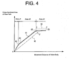
- FIG. 4 is a graph for specifying the shape of the connecting portion 76 of the first embodiment.
- the cross-sectional area of the flow path increases slightly gradually in accordance with the increase of the movement distance of the valve body 72.
- the cross-sectional area of the flow path has reached at the maximum value and maintains the value constantly.
- the characteristic curve of the graph G1 shows a continuous curve at the boundary points from the area J1 to the area J2, and from the area J2 to the area J3. That enables a continuous flow control even around the boundary points.
- the graph G1 is a smooth curve which shows the relation between the cross-sectional area of the flow path and the movement distance of the valve body 72, thereby enables a continuous flow control. That is, when the movement distance of the valve body 72 is determined, the cross-sectional area of the flow path is unambiguously determined, and the flow rate flowing through the flow path is determined.
- a graph G0 in FIG. 4 shows characteristics of a conventional art and is indicated as a dotted line which connects points A, B, C and D. The graph G0 shows a discontinuous curve at the points B and C.
- FIG. 5A shows a state of the displacement control valve 50 which is transited from a closed state to a opened state to perform the displacement control.
- the valve body 72 is moved apart from the valve hole 54. That is, the plane end surface 72a of the valve body 72 is spaced away from the valve seat 54a.
- the displacement control valve 50 is transited from the closed state to the opened state.
- the cross-sectional area of the flow path is determined by a distance between the plane end surface 72a of the valve body 72 and the valve seat 54a.
- the cross-sectional area of the flow path increases substantially linearly (shown by the area J1 in FIG. 4),
- the cross-sectional area of the flow path is determined by the positional relation between the arc-curved surface 76a of the connecting portion 76 and the valve hole 54.
- the cross-sectional area of the flow path increases slightly gradually in accordance with the movement distance of the valve body 72 (shown by the area J2 in FIG. 4).
- the plane end surface 72a of the valve body 72 and the arc-curved surface 76a of the connecting portion 76 are connected with a continuous surface so that the cross-sectional area of the flow path changes smoothly as shown by the smooth curve around the boundary point from the area J1 to the area J2 in FIG. 4.
- the cross-sectional area of the flow path which is determined by the valve hole 54 and the second shaft portion 75, becomes the maximum, and the refrigerant flows sufficiently through the valve hole 54 (shown by the area J3 in FIG. 4).
- the arc-curved surface 76a of the connecting portion 76 and the circumferential surface of the second shaft portion 75 are formed to be connected with a continuous surface so that the cross-sectional area of the flow path changes smoothly as shown by the smooth curve around the boundary point from the area J2 to the area J3 in FIG. 4.
- the opening and closing of the valve hole 54 by the valve body 72 is determined by the balance between the exciting force of the solenoid 66, the urging force of the coil spring 74 and the pressure sensing mechanism 62.
- the cross-sectional area of the flow path is unambiguously determined, and the flow rate of the refrigerant is determined accordingly.
- the pressure in the crank chamber 16 is determined by the flow rate of the refrigerant supplied to the crank chamber 16 so that the inclination angle of the swash plate 23 is determined.
- the change of the cross-sectional area of the flow path in accordance with movement distance of the valve body 72 draws a smooth and continuous curve (graph G1 in FIG. 4), and the flow rate control can be continuous and smooth.
- the displacement control valve 50 is in a state that the movable core 68 is the farthest from the fixed core 67.
- the solenoid 66 is not excited, and the rod 70 is moved toward the solenoid 66 by the urging force of the coil spring 74 and the pressure sensing mechanism 62.
- the connecting portion 76 of the valve body 72 is out of the valve hole 54, and the cross-sectional area of the flow path is maximum, which is determined by the valve hole 54 and the second shaft portion 75.
- the rod 70 is moved in the direction to close the valve hole 54 (upward in FIG. 5), and part of the connecting portion 76 is inserted into the valve hole 54 so as to decrease the cross-sectional area in accordance with the position of the arc-curved surface 76a.
- the state of the displacement control valve 50 is transited from the long movement distance state of the valve body 72 to the short movement distance state thereby decreasing the cross-sectional area of the flow path.
- the operation of the control valve 50 transited from the opened state to the closed state is the reverse operation of the transition from the closed state to the opened state, and the explanation is omitted.
- the pressure in the crank chamber 16 is minimum, and the inclination angle of the swash plate 23 is maximum so as to operate the compressor at the maximum displacement. Because of the sealing performance by the contact between the plane end surface 72a and the valve seat 54a, the refrigerant with high pressure does not leak into the crank chamber 16 through the valve hole 54.
- the displacement control valve 50 of the present embodiment has the following advantageous effects.
- the present invention is not limited to the first through the third embodiments, but may be variously modified within the scope of the invention.
- the above embodiments may be modified as follows.
- the displacement control valve has the pressure sensing mechanism which senses the pressure difference between the upstream circuit and the downstream circuit of the discharge pressure region. That is, the pressure sensing mechanism is a type which senses the pressure difference caused by the flow rate.
- the present invention may be applicable to a displacement control valve with a pressure sensing mechanism which senses a pressure difference between a suction pressure region and a discharge pressure region.
- the present invention may also be applicable to a displacement control valve with a pressure sensing mechanism which senses a pressure difference between a discharge pressure region and a control pressure region, or a pressure difference based on a suction pressure region.
- a refrigerant passage or a chamber which is required may be added to the displacement control valve in accordance with the arrangement of a pressure sensing chamber and a valve chamber.
- the present invention may be applicable to a displacement control valve which is located in a control passage which connects a crank chamber and a suction chamber to adjust the opening degree of the control passage.
- the throttle is provided in the external refrigerant circuit to divide the external refrigerant circuit into the upstream circuit and the downstream circuit
- a throttle may be provided in a discharge passage and pressure in a discharge chamber or pressure at an upstream side of the throttle may be introduced into a high-pressure chamber in a displacement control valve, and pressure at an downstream side of the throttle or pressure in a discharge pressure region in the external refrigerant circuit is introduced into a low-pressure chamber in the displacement control valve,
- the refrigerant in the discharge pressure region is introduced into the crank chamber and is shut from the crank chamber by the displacement control valve.
- the present invention may be applicable to a three-way valve which has a passage from a discharge pressure region to the crank chamber.
- the type of the refrigerant is not specified. Fluorocarbon-based gas or carbon dioxide is for example preferably used.
- the refrigerant may be gas or liquid.
- the step of the third embodiment may be provided at the connecting portion of the connecting portion 86 and the second shaft portion 85 in the second embodiment. In this case, the maximum cross-sectional area of the flow path can be increased.
- the diameter R1 of the connecting portion 76, 95 adjacent to the plane end surface 72a, 93a of the valve body 72, 93 is set smaller than the outside diameter of the valve body 72, 93 and substantially equal to the inside diameter of the valve hole 54.
- the diameter R1 may be set smaller than the inside diameter of the valve hole 54. In this case, the axial length of the connecting portion can be shortened and the movement distance of the rod can be set further shorter.
- a displacement control valve for a variable displacement compressor has a control passage, a valve hole formed in the control passage, a first shaft portion having a valve body, and a connecting portion connected to the end portion of the valve body.
- the control passage is connected to a crank chamber for controlling the pressure in the crank chamber for adjusting the discharge displacement of the compressor.
- the valve body is formed at an end portion of the first shaft portion to open and close the valve hole.
- the connecting portion connected to the end portion of the valve body is disposed into the valve hole, and a circumferential surface of the connecting portion has a curved surface so as to be flared out at an end of the connecting portion.
Landscapes
- Engineering & Computer Science (AREA)
- Mechanical Engineering (AREA)
- General Engineering & Computer Science (AREA)
- Compressors, Vaccum Pumps And Other Relevant Systems (AREA)
- Control Of Positive-Displacement Pumps (AREA)
Abstract
Description
- The present invention relates to a displacement control valve of a variable displacement compressor which is used in a vehicle air conditioner.
- Generally, a variable displacement compressor (hereinafter referred to as "compressor") is known as a compressor for use in a vehicle air conditioner, which variably controls the displacement. In this type of compressor, a swash plate is accommodated in a crank chamber and is inclinable with respect to a drive shaft. As the pressure in the crank chamber increases, the inclination of the swash plate approaches to be perpendicular to the axis of the drive shaft (the inclination angle of the swash plate decreases). As the pressure in the crank chamber decreases, the swash plate is inclined so that the inclination of the swash plate approaches to the axis of the drive shaft (the inclination angle of the swash plate increases). The compressor has a plurarity of pistons , and the stroke of the pistons changes in accordance with the inclination angle of the swash plate. For example, when the pressure in the crank chamber is high and the inclination angle of the swash plate is small, the stroke of the piston is short. When the pressure in the crank chamber is low and the inclination angle of the swash plate is large, the stroke of the pistons is long. As the stroke of the pistons decreases, the displacement of the compressor decreases. As the stroke of the pistons increases, the displacement of the compressor increases.
- Japanese Unexamined Patent Application Publication (KOKAI)
No. 9-268973 U.S. Patent No. 5890876 discloses a displacement control valve 49 for a compressor. The displacement control valve 49 has avalve housing 61 and asolenoid 62 joined thereto. Avalve chamber 63 is defined by thevalve housing 61 and thesolenoid 62, and is connected to adischarge chamber 38. Avalve body 64 is arranged in thevalve chamber 63 to open and close avalve hole 66. Thevalve hole 66 is connected to acrank chamber 15. - The displacement control valve 49 has a
pressure sensing chamber 68 which is connected to asuction passage 32 and provided abellows 70 therein. Thebellows 70 is connected to thevalve body 64 by arod 72 which has alarge diameter portion 72a and a small diameter portion 72b. The large-diameter portion 72a extends through and slides with respect to aguide hole 71. The small-diameter portion 72b extends through thevalve hole 66. The small-diameter portion 72b is connected to a top end 64a of thevalve body 64 by atapered portion 73. The diameter of thetapered portion 73 increases toward thevalve body 64. - When the
valve hole 66 is opened, the refrigerant gas in thedischarge chamber 38 flows into thecrank chamber 15. When thevalve hole 66 is closed by thevalve body 64, the refrigerant is not introduced from thedischarge chamber 38 to thecrank chamber 15. - When the
solenoid 62 is excited and thevalve body 64 is moved in the direction to close thevalve hole 66, the amount of the refrigerant which flows from thedischarge chamber 38 to thecrank chamber 15 is decreased so that the pressure in thecrank chamber 15 decreases and the inclination angle of aswash plate 22 increases. When thesolenoid 62 is not excited and thevalve body 64 is moved away from thevalve hole 66, the amount of the refrigerant from thedischarge chamber 38 to thecrank chamber 15 is increased so that the pressure in thecrank chamber 15 increases and the inclination angle of theswash plate 22 decreases. Since thetapered portion 73 is formed at the top end 64a of thevalve body 64, and the diameter of thetapered portion 73 adjacent to the top end 64a is larger than the diameter of thetapered portion 73 adjacent to therod 72, the cross-sectional area of the flow path of thevalve hole 66 varies gradually in accordance with the movement of thetapered portion 73, when thevalve body 64 opens and closes thevalve hole 66. Thus, due to opening and closing of the displacement control valve 49, rapid start and stop of the supply of the highly-pressurized refrigerant into thecrank chamber 15 may be prevented. - In the
Japanese Unexamined Patent Application Publication No. 9-268973 tapered portion 73 and the top end 64a of thevalve body 64, and a continuous flow rate control and the stable control may not be accomplished. For example, in a graph shown in FIG. 8, the movement distance of thevalve body 64 is indicated by a horizontal axis, and the cross-sectional area in the flow path is indicated by a vertical axis. A characteristic of the conventional art is shown by a characteristic curve indicated by a graph G0, which connects points A, B, C, and D. The characteristic curve G0 is discontinuous at the point B and C. The cross-sectional area of the flow path varies discontinuously in accordance with the movement distance of thevalve body 64. Especially at the neighborhood of the point B which corresponds to a beginning of the displacement control, the graph G0 varies discontinuously. The point B corresponds to the discontinuous connecting part of the top end 64a of thevalve body 64 and the larger-diameter side of thetapered portion 73. The point C corresponds to the discontinuous connecting part of the small-diameter portion 72b of thetapered portion 73 and the smaller-diameter side of thepressure sensing rod 72. Thus, at the neighborhood of the point B and C, the continuous flow rate control and thereby a target displacement may not be accomplished. - The present invention which is made in view of the above problems is directed to a displacement control valve for a variable displacement compressor which has a continuous flow rate control and an improved stability in control.
- An aspect in accordance with the present invention provides a displacement control valve for a variable displacement compressor. The displacement control valve has a control passage, a valve hole formed in the control passage, a first shaft portion including a valve body, and a connecting portion connected to the end portion of the valve body. The control passage is connected to a crank chamber for controlling the pressure in the crank chamber for adjusting the discharge displacement of the compressor. The valve body is formed at an end portion of the first shaft portion to open and close the valve hole. The connecting portion connected to the end portion of the valve body is disposed into the valve hole, and a circumferential surface of the connecting portion has a curved surface so as to be flared out at an end of the connecting portion.
- Other aspects and advantages of the invention will become apparent from the following description, taken in conjunction with the accompanying drawings, illustrating by way of example the principles of the invention.
- The features of the present invention that are believed to be novel are set forth with particularity in the appended claims. The invention together with objects and advantages thereof, may best be understood by reference to the following description of the presently preferred embodiments together with the accompanying drawings in which:
- FIG. 1 is a longitudinal cross-sectional view schematically showing a compressor according to a first embodiment;
- FIG. 2 is a longitudinal cross-sectional view schematically showing a displacement control valve according to the first embodiment;
- FIG. 3 is a partial sectional view showing a connecting portion of the displacement control valve according to the first embodiment;
- FIG. 4 is a graph for specifying the shape of the connecting portion according to the first embodiment, a second embodiment, and a third embodiments;
- FIG. 5A is a partial sectional view for explaining operation of the displacement control valve according to the first embodiment, when the displacement control valve starts to be opened;
- FIG. 5B is a partial sectional view for explaining operation of the displacement control valve according to the first embodiment, when the displacement control valve is fully opened;
- FIG. 6 is a partial sectional view showing a connecting portion of the displacement control valve according to the second embodiment;
- FIG 7 is a partial sectional view showing a connecting portion of the displacement control valve according to the third embodiment; and
- FIG. 8 is a graph for specifying a shape of a connecting portion according to a conventional art.
- The following will describe a displacement control valve for a variable displacement compressor (hereinafter referred to as "displacement control valve) of a first preferred embodiment according to the present invention with reference to FiGs. 1 through 5. Referring to FIG. 1, a variable displacement compressor 10 (hereinafter referred to as "compressor") includes a housing, which forms its configuration. The
housing 11 includes acylinder block 12 having a plurarity ofcylinder bores 12a formed therein, afront housing 13 which is joined to the front end (left side in FIG. 1) of thecylinder block 12, and arear housing 14 which is joined to the rear end (right side in FIG. 1) of thecylinder block 12. Abolt 15 is passed through thefront housing 13, thecylinder block 12 and therear housing 14 to tighten those components in the axial direction of thebolt 15, so that those components are integrally fixed to form thehousing 11. - The
front housing 13 has acrank chamber 16 defined therein, whose rear end is closed by thecylinder block 12. A drive shaft 17 is rotatably supported by aradial bearing 18 provided in thefront housing 13 and aradial bearing 19 provided in thecylinder block 12 so as to extend through the vicinity of the center of thecrank chamber 16. Asealing mechanism 20 is provided in front of theradial bearing 18 which supports the front part of the drive shaft 17 so as to keep in slide contact with the circumferential surface of the drive shaft 17. Thesealing mechanism 20 has a lip seal member and the like to prevent refrigerant in thecrank chamber 16 from leaking through a clearance between thefront housing 13 and the drive shaft 17. The front end of the drive shaft 17 is connected to an external drive source (not shown) through a power transmission mechanism (not shown) so that the drive shaft 17 is rotated by the external drive source. - A
lug plate 21 is fixedly mounted on the drive shaft 17 in thecrank chamber 16 so as to integrally rotate with the drive shaft 17. Aswash plate 23 which constitutes adisplacement changing mechanism 22 is supported by the drive shaft 17 in the rear side of thelug plate 21 so as to slide along and incline relative to the axial direction of the drive shaft 17, Ahinge mechanism 24 is interposed between theswash plate 23 and thelug plate 21. Theswash plate 23 is connected to thelug plate 21 through thehinge mechanism 24 so as to synchronously rotate with and incline relative to thelug plate 21 and the drive shaft 17. - A coil spring 25 is wound around the drive shaft 17 between the
lug plate 21 and theswash plate 23. Acylindrical body 26 is slidably fitted on the drive shaft 17, and is urged by the coil spring 25 rearward. Theswash plate 23 is continuously urged rearward through thecylindrical body 26 urged by the coil spring 25. That is, theswash plate 23 is urged continuously in a direction to decrease the inclination angle of theswash plate 23. It is noted that an inclination angle of theswash plate 23 represents an angle formed by a plane perpendicular to the drive shaft 17 and the plane of theswash plate 23. Astopper 23a protrudes from the front surface of theswash plate 23. The maximum inclination angle of theswash plate 23 is regulated by the contact between thelug plate 21 and thestopper 23a as shown in FIG. 1. A retainingring 27 is fitted on the drive shaft 17 in the rear side of theswash plate 23, and acoil spring 28 is wound around the drive shaft 17 in front of the retainingring 27. The minimum inclination angle of theswash plate 23 is regulated by the contact between theswash plate 23 and the front end of thecoil spring 28. In FIG 1, theswash plate 23 indicated by a solid line is at a position of the maximum inclination angle, and theswash plate 23 indicated by a phantom line is at a position of the minimum inclination angle. - A single-headed
piston 29 is disposed in each cylinder bore 12a of thecylinder block 12 respectively so as to reciprocate therein. Acompression chamber 31 is defined by each cylinder bore 12a and each head of thepiston 29. A neck portion of thepiston 29 engages with the periphery of theswash plate 23 through a pair ofshoes 30. As theswash plate 23 is rotated with the drive shaft 17, the rotation of theswash plate 23 is converted to the reciprocation movement of eachpiston 29 throughshoes 30. As shown in FIG. 1, the front end of therear housing 14 is joined to the rear end of thecylinder block 12. Asuction chamber 38 is defined at the center of therear housing 14. Adischarge chamber 39 is defined at the periphery of therear housing 14. Thedischarge chamber 39 is separated from thesuction chamber 38 by apartition wall 14a. - A
valve plate 32, valvebody forming plates retainer 35 are interposed between thecylinder block 12 and therear housing 14. Thevalve plate 32 forms acompression chamber 31 in each cylinder bore 12a together with eachpiston 29. Suction ports 36 anddischarge ports 37 are formed in thevalve plate 32. Each suction port 36 corresponds to one of the cylinder bore 12a to communicate the cylinder bore 12a to thesuction chamber 38. Eachdischarge port 37 corresponds to one of the cylinder bore 12a to communicate the cylinder bore 12a to thedischarge chamber 39. The valvebody forming plate 33 has suction valves (not shown). Each suction valve corresponds to one of the suction ports 36 and is interposed between thesuction chamber 38 and the correspondingcompression chamber 31. The valvebody forming plate 34 has reedtype discharge valves 34a. Eachdischarge valve 34a corresponds to one of thedischarge ports 37 and is interposed between thedischarge port 37 and thedischarge chamber 39. The retainer regulates the maximum opening degree of eachdischarge valve 34a. - While the
piston 29 moves from its top dead center to its bottom center, the refrigerant in thesuction chamber 38 is introduced into thecompression chamber 31 through the suction port 36 and the suction valve (not shown). While thepiston 29 moves from its bottom dead center to its top dead center, the refrigerant introduced into thecompression chamber 31, is compressed to a predetermined pressure and then discharged to thedischarge chamber 39 through thedischarge port 37 and thedischarge valve 34a. The inclination angle of theswash plate 23 is determined by a moment caused by the pressure of the refrigerant, and the like. The moment caused by the pressure of the refrigerant is the moment generated on the basis of the correlation between the pressure in eachcompression chamber 31 and the pressure in thecrank chamber 16 which is applied to the back surface of eachpiston 29. The moment is applied to theswash plate 23 in the direction to increase or to decrease the inclination angle in accordance with fluctuation of the pressure in thecrank chamber 16. In thecompressor 10 of this embodiment, a control valve which is described after, controls the pressure in thecrank chamber 16, and varies the moment caused by the pressure of the refrigerant appropriately, so that the inclination angle of theswash plate 23 is set at an optional angle between the minimum inclination angle and the maximum inclination angle. - An external refrigerant circuit will be described. The
suction chamber 38 is connected to an externalrefrigerant circuit 42 through asuction passage 40 formed in therear housing 14, and the refrigerant in the externalrefrigerant circuit 42 is supplied to thesuction chamber 38 through thesuction passage 40. In this embodiment, a suction pressure region includes thesuction chamber 38 and thesuction passage 40. Thedischarge chamber 39 is connected to the externalrefrigerant circuit 42 through adischarge passage 41 formed in therear housing 14, and the refrigerant in thedischarge chamber 39 is discharged to the externalrefrigerant circuit 42. The externalrefrigerant circuit 42 includes acondenser 43, anexpansion valve 44, and aheat exchanger 45. Thecondenser 43 absorbs heat from the refrigerant, and theheat exchanger 45 transmits heat to the refrigerant. - The
expansion valve 44 is a temperature sensing type automatic expansion valve for controlling the flow rate of the refrigerant in accordance with the temperature fluctuation of the refrigerant at an outlet of theheat exchanger 43. Athrottle 46 is provided on the downstream side of thedischarge passage 41 and on the upstream side of theheat exchanger 43 in the externalrefrigerant circuit 42. In this embodiment, anupstream circuit 42a is defined by a part of the externalrefrigerant circuit 42 between thedischarge passage 41 and thethrottle 46, and adownstream circuit 42b is defined by a part of the externalrefrigerant circuit 42 between thethrottle 46 and theheat exchanger 43. A discharge pressure region includes thedischarge chamber 39, theupstream circuit 42a, and thedownstream circuit 42b in this embodiment. - As shown in FIG 1, a
displacement control valve 50 is provided in therear housing 14 to supply the refrigerant in the discharge pressure region to the crankchamber 16. As shown in FIG.2. thedisplacement control valve 50 includes avalve housing 51, asolenoid 66, arod 70 including avalve body 72, and apressure sensing mechanism 62 as main parts. Thevalve housing 51 is substantially cylindrical shape and has a plurarity of chambers therein. The solenoid is connected to thevalve housing 51. Therod 70 including thevalve body 72 serves as a reciprocation body, and moves in one direction by the exciting force of thesolenoid 66, and moves in the opposite direction by thepressure sensing mechanism 62. - A
pressure sensing chamber 52 is defined in thevalve housing 51 adjacent to a first end, or a upper end (upper side of FIG 1). Anend wall member 58 is fitted at the upper end of thepressure sensing chamber 52. Thepressure sensing chamber 52 accommodates thepressure sensing mechanism 62 therein. Thepressure sensing mechanism 62 has abellows 63 which divides thepressure sensing chamber 52 into the low-pressure chamber 52a and a high-pressure chamber 52b. A fixed end, or the upper end of thebellows 63 is fixed to theend wall member 58. The high-pressure chamber 52b is defined inside the bellows 63. The low-pressure chamber 52a is defined outside the bellows 63. - A
valve chamber 53 is defined next to thepressure sensing chamber 52. Thevalve chamber 53 is separated from thepressure sensing chamber 52 by apartition wall 51a. Thepartition wall 51a has avalve hole 54 therethrough and avalve seat 54a around thevalve hole 54 on the side of thevalve chamber 53, Thevalve housing 51 has afirst communication port 55 as a first port and asecond communication port 57 as a second port. Thefirst communication port 55 connects the low-pressure chamber 52a of thepressure sensing chamber 52 to thedownstream circuit 42b. Thesecond communication port 57 connects thevalve chamber 53 to the crankchamber 16. - A supply passage as a control passage is formed in the
valve housing 51. Avalve hole 54 is formed in the control passage. The control passage communicates thefirst communication port 55 to thesecond communication port 57 through thevalve hole 54. That is, the supply passage is constituted between thefirst communication port 55 and thesecond communication port 57, and includes the low-pressure chamber 52a which is part of thepressure sensing chamber 52, thevalve chamber 53, and thevalve hole 54. Thefirst communication port 55 is connected to thedownstream circuit 42b through afirst communication passage 59, Thesecond communication port 57 is connected to the crankchamber 16 through asecond communication passage 61. The pressure in thedischarge chamber 39 and theupstream circuit 42a is high, and the pressure in thedownstream circuit 42b, thecrank chamber 16, and thesuction chamber 38 is decreased in this order. It is noted that when thecompressor 10 is operated at the maximum displacement, the pressure in thesuction chamber 38 and thecrank chamber 16 is substantially equal. - In the
pressure sensing chamber 52, amovable member 64 is connected on a movable end, or the lower end of thebellows 63. The high-pressure chamber 52b is defined inside thebellows 63, and the low-pressure chamber 52a is defined outside the bellows 63. Athird communication port 56 is formed in theend wall member 58 and connects the high-pressure chamber 52b to theupstream circuit 42a through athird communication passage 60. The pressure difference between the low-pressure chamber 52a and the high-pressure chamber 52b gives a force to themovable member 64 in the direction to extend thebellows 63. Accordingly, when the pressure difference between the low-pressure chamber 52a and the high-pressure chamber 52b exists, the force in a direction to extend thebellows 63 is given to themovable member 64. - The
solenoid 66 is connected to a lower end (lower side of FIG. 1) of thevalve housing 51 adjacent to thevalve chamber 53. Thesolenoid 66 has a fixedcore 67 which faces thevalve chamber 53, and the fixed core closes the lower end of thevalve housing 51. Thesolenoid 66 has amovable core 68 and anelectromagnetic coil 69. Themovable core 68 faces the fixedcore 67. Theelectromagnetic coil 69 is formed so as to surround the fixedcore 67 and themovable core 68. The fixedcore 67 has a throughhole 67a formed through the center thereof, and the throughhole 67a has a larger diameter than thevalve hole 54. The axial center of the throughhole 67a is coaxial with that of thevalve hole 54. The fixedcore 67 attracts themovable core 68 when electric current is supplied to theelectromagnetic coil 69 to excite theelectromagnetic coil 69. Thesolenoid 66 is controlled by a current supply control (a duty control) based on a duty ratio of a control unit (not shown). - The
rod 70 will now be described. In the first embodiment, therod 70 is disposed in thevalve housing 51, and includes afirst shaft portion 71 whose end portion serves as thevalve body 72. Thefirst shaft portion 71 has a round-bar shape. Thefirst shaft portion 71 is surrounded by thesolenoid 66, and a part of thefirst shaft portion 71 is disposed in thevalve chamber 53. Thefirst shaft portion 71 has a larger diameter than thevalve hole 54. In this embodiment, most of thefirst shaft portion 71 is located in the throughhole 67a of the fixedcore 67 so as to slide along the throughhole 67a of the fixedcore 67. The lower end of thefirst shaft portion 71 adjacent to thesolenoid 66 is connected to themovable core 68. Since the diameter of thefirst shaft portion 71 is set larger than that of thevalve hole 54, the upper end of thefirst shaft portion 71 adjacent to thevalve hole 54 serves as thevalve body 72. That is, when thefirst shaft portion 71 which includes thevalve body 72 is in contact with thepartition wall 51 a which faces thevalve chamber 53, thevalve hole 54 is closed. When the contact between thefirst shaft portion 71 and thepartition wall 51 a is released, thevalve hole 54 is opened. - A
spring receiving body 73 is mounted on thefirst shaft portion 71 and located in thevalve chamber 53. Thespring receiving body 73 has a flange. Acoil spring 74 is interposed between thespring receiving body 73 and thepartition wall 51a. When the exciting force of theelectromagnetic coil 69 is not applied to themovable core 68, thecoil spring 74 moves therod 70 toward thesolenoid 66. That is, thecoil spring 74 urges thefirst shaft portion 71 in the direction to move themovable core 68 away from the fixedcore 67 through thespring receiving body 73. A connectingportion 76 connects the end portion of thefirst shaft portion 71 and a second shaft portion. Thesecond shaft portion 75 is a round-bar shape, and is coaxial with thefirst shaft portion 71. Thesecond shaft portion 75 has a sufficiently smaller diameter than thevalve hole 54 and extends through thevalve hole 54 to be connected to thepressure sensing mechanism 62. A clearance with an annular cross section formed by thevalve hole 54 and the rod 70 (thesecond shaft portion 75 or the connecting portion 76) constitutes a flow path, when thevalve body 72 opens thevalve hole 54. The flow path forms a part of the control passage. - The connecting
portion 76 will now be described. As shown in FIG. 3, the lower end (lower side of FIG. 3) of the connectingportion 76 is connected to thefirst shaft portion 71, or the end portion of thevalve body 72, and the upper end of the connectingportion 76 is connected to thesecond shaft portion 75. The connectingportion 76 is integrally formed with thefirst shaft portion 71 and thesecond shaft portion 75 to constitute a part of therod 70. The connectingportion 76 is disposed into thevalve hole 54 so that the vicinity of the axial center of the connectingportion 76 protrudes into thevalve hole 54 at the upper end portion of thevalve body 72. That is, the connectingportion 76 protrudes into thevalve hole 54 from aplane end surface 72a of thevalve body 72, and is coaxial with therod 70. The configuration of the connectingportion 76 has a shape to be flared out at the lower end of the connectingportion 76 adjacent to thevalve body 72, and the circumferential surface of the connectingportion 76 is formed with an arc-shapedcurved surface 76a which connects theplane end surface 72a of thevalve body 72 and thesecond shaft portion 75 in a round chambered manner. In other words, the cross-section of the connectingportion 76 cut along a longitudinal axis of therod 70 has an arc-shaped curve on both sides of the axis so as to be flared out at the lower end of the connectingportion 76 adjacent to thevalve body 72. - The diameter of the lower end of the connecting
portion 76 adjacent to thefirst shaft portion 71 is indicated as R1. In other words, the diameter R1 is the diameter of the lower end of the connectingportion 76 adjacent to theplane end surface 72a of thevalve body 72. The diameter R1 is set smaller than the outside diameter of thevalve body 72, and substantially equal to the inside diameter of thevalve hole 54. The diameter of the upper end of the connectingportion 76 adjacent to thesecond shaft portion 75 is indicated as R2. The diameter R2 is substantially equal to the diameter of thesecond shaft portion 75. That is, the diameter of the connectingportion 76 decreases from the end portion of thevalve body 72 toward thesecond shaft portion 75, and the circumferential surface of the connectingportion 76 is formed as an arc-shapedcurved surface 76a which connects theplane end surface 72a of thevalve body 72 and the circumferential surface of thesecond shaft portion 75. Thus, the end portion of thevalve body 72 and thesecond shaft portion 75 are connected by the continuous curved surface. Theplane end surface 72a of thevalve body 72 adjacent to the connectingportion 76 closes thevalve hole 54 by making contact with thevalve seat 54a. - FIG. 4 is a graph for specifying the shape of the connecting
portion 76 of the first embodiment. The movement distance of thevalve body 72 indicated by a horizontal axis, and the cross-sectional area in the flow path is indicated by a vertical axis, and the shape of the connectingportion 76 is specified by a characteristic curve indicated by a graphG1, or a solid line. That is, the graph G1 is divided into three areas J1, J2, J3, which are indicated in ascending order of the movement distance, and the area J1 is the nearest to the origin (point A). In the area J1, immediately after the opening of thevalve 50, the cross-sectional area of the flow path increases rapidly in accordance with the increase of the movement distance of thevalve body 72. In the area J2, the cross-sectional area of the flow path increases slightly gradually in accordance with the increase of the movement distance of thevalve body 72. In the area J3, the cross-sectional area of the flow path has reached at the maximum value and maintains the value constantly. The characteristic curve of the graph G1 shows a continuous curve at the boundary points from the area J1 to the area J2, and from the area J2 to the area J3. That enables a continuous flow control even around the boundary points. - Accordingly, in a predetermined range of the movement distance of the
valve body 72, the graph G1 is a smooth curve which shows the relation between the cross-sectional area of the flow path and the movement distance of thevalve body 72, thereby enables a continuous flow control. That is, when the movement distance of thevalve body 72 is determined, the cross-sectional area of the flow path is unambiguously determined, and the flow rate flowing through the flow path is determined. For reference, a graph G0 in FIG. 4 shows characteristics of a conventional art and is indicated as a dotted line which connects points A, B, C and D. The graph G0 shows a discontinuous curve at the points B and C. - Operation of the displacement control valve of the present embodiment will now be described with reference to FIGS. 5A and 5B. As external heat load such as temperature in a vehicle compartment rises, the
solenoid 66 is excited by electric current supplied thereto, Accordingly themovable core 68 is moved to the fixedcore 67, and therod 70 is moved in the direction toward thepressure sensing mechanism 62. On the other hand, urging force is applied to thebellows 63 of thepressure sensing mechanism 62 in accordance with the pressure difference between theupstream circuit 42a and thedownstream circuit 42b. The moving direction of therod 70 is determined by the balance of the urging force of thebellows 63, the urging force of thecoil spring 74, and the exciting force of thesolenoid 66. As the exciting force of thesolenoid 66 becomes greater to the urging forces of thebellows 63 and thecoil spring 74, therod 70 is moved in the direction to open the valve hole 54 (downward in FIG. 5). - FIG. 5A shows a state of the
displacement control valve 50 which is transited from a closed state to a opened state to perform the displacement control. When therod 70 is moved in the direction to open thevalve hole 54, thevalve body 72 is moved apart from thevalve hole 54. That is, theplane end surface 72a of thevalve body 72 is spaced away from thevalve seat 54a. Thus, thedisplacement control valve 50 is transited from the closed state to the opened state. Immediately after the opening of thevalve hole 54, the cross-sectional area of the flow path is determined by a distance between theplane end surface 72a of thevalve body 72 and thevalve seat 54a. When the distance between theplane end surface 72a and thevalve seat 54a increases, the cross-sectional area of the flow path increases substantially linearly (shown by the area J1 in FIG. 4), When therod 70 moves further in the direction to open thevalve hole 54, the cross-sectional area of the flow path is determined by the positional relation between the arc-curved surface 76a of the connectingportion 76 and thevalve hole 54. Thus, the cross-sectional area of the flow path increases slightly gradually in accordance with the movement distance of the valve body 72 (shown by the area J2 in FIG. 4). - The
plane end surface 72a of thevalve body 72 and the arc-curved surface 76a of the connectingportion 76 are connected with a continuous surface so that the cross-sectional area of the flow path changes smoothly as shown by the smooth curve around the boundary point from the area J1 to the area J2 in FIG. 4. When therod 70 moves and the connectingportion 76 is out of thevalve hole 54, the cross-sectional area of the flow path, which is determined by thevalve hole 54 and thesecond shaft portion 75, becomes the maximum, and the refrigerant flows sufficiently through the valve hole 54 (shown by the area J3 in FIG. 4). The arc-curved surface 76a of the connectingportion 76 and the circumferential surface of thesecond shaft portion 75 are formed to be connected with a continuous surface so that the cross-sectional area of the flow path changes smoothly as shown by the smooth curve around the boundary point from the area J2 to the area J3 in FIG. 4. - As the
valve hole 54 is opened, part of the refrigerant with high pressure in thedownstream circuit 42b flows through thefirst communication passage 59 andfirst communication port 55 into the low-pressure chamber 52a in thepressure sensing chamber 52. The refrigerant in the low-pressure chamber 52a flows through the flow path formed by thevalve body 72 and thevalve hole 54 into thevalve chamber 53. Then the refrigerant flows through thesecond communication port 57 and thesecond communication passage 61 into thecrank chamber 16. The inclination angle of theswash plate 23 is determined by the pressure in thecrank chamber 16. Since the refrigerant with high pressure is supplied to the crankchamber 16, the pressure in thecrank chamber 16 increases and the inclination angle of theswash plate 23 decreases. - The opening and closing of the
valve hole 54 by thevalve body 72 is determined by the balance between the exciting force of thesolenoid 66, the urging force of thecoil spring 74 and thepressure sensing mechanism 62. When the movement distance of thevalve body 72 is determined, the cross-sectional area of the flow path is unambiguously determined, and the flow rate of the refrigerant is determined accordingly. The pressure in thecrank chamber 16 is determined by the flow rate of the refrigerant supplied to the crankchamber 16 so that the inclination angle of theswash plate 23 is determined. In a determined range of the movement distance of thevalve body 72, the change of the cross-sectional area of the flow path in accordance with movement distance of thevalve body 72 draws a smooth and continuous curve (graph G1 in FIG. 4), and the flow rate control can be continuous and smooth. - As external heat load such as temperature in a vehicle compartment decreases, the current to the
solenoid 66 decreases. In FIG 5B thedisplacement control valve 50 is in a state that themovable core 68 is the farthest from the fixedcore 67. At the time, thesolenoid 66 is not excited, and therod 70 is moved toward thesolenoid 66 by the urging force of thecoil spring 74 and thepressure sensing mechanism 62. Thus the movement distance of thevalve body 72 is the maximum. The connectingportion 76 of thevalve body 72 is out of thevalve hole 54, and the cross-sectional area of the flow path is maximum, which is determined by thevalve hole 54 and thesecond shaft portion 75. Since the refrigerant is supplied to the crankchamber 16 through the flow path with the maximum cross-sectional area, the pressure in thecrank chamber 16 becomes maximum, and the inclination angle of theswash plate 23 becomes minimum accordingly so that thecompressor 10 is operated at the minimum displacement. - When the
displacement control valve 50 of thecompressor 10 is transited from the opened state to the closed state, therod 70 is moved in the direction to close the valve hole 54 (upward in FIG. 5), and part of the connectingportion 76 is inserted into thevalve hole 54 so as to decrease the cross-sectional area in accordance with the position of the arc-curved surface 76a. In this case, the state of thedisplacement control valve 50 is transited from the long movement distance state of thevalve body 72 to the short movement distance state thereby decreasing the cross-sectional area of the flow path. The operation of thecontrol valve 50 transited from the opened state to the closed state is the reverse operation of the transition from the closed state to the opened state, and the explanation is omitted. - When the
valve body 72 of therod 70 is moved in the direction to close thevalve hole 54 and the cross-sectional area of the flow path decreases, the flow rate of the refrigerant which passes through the flow path decreases, and the refrigerant which is introduced into thecrank chamber 16 decreases accordingly. Thus the pressure in thecrank chamber 16 decreases, and the inclination angle of theswash plate 23 increases so as to increase the displacement of thecompressor 10. When the cross-sectional area of the flow path is zero, that is, when theplane end surface 72a of thevalve body 72 is in contact with thevalve seat 54a and the movement distance of thevalve body 72 is zero, thevalve hole 54 is closed completely and the refrigerant is not supplied to the crankchamber 16. Accordingly, the pressure in thecrank chamber 16 is minimum, and the inclination angle of theswash plate 23 is maximum so as to operate the compressor at the maximum displacement. Because of the sealing performance by the contact between theplane end surface 72a and thevalve seat 54a, the refrigerant with high pressure does not leak into thecrank chamber 16 through thevalve hole 54. - The
displacement control valve 50 of the present embodiment has the following advantageous effects. - (1) The end portion of the
valve body 72 has the connectingportion 76 protruding into thevalve hole 54, and the configuration of the connectingportion 76 has a curved surface which protrudes at the vicinity of the axial center of thevalve body 72. In other words, the end portion of thevalve body 72 and the cylindricalsecond shaft portion 75 which is connected adjacent to thevalve body 72 is connected with an arc-shaped curve. Thus, the cross-sectional area of the flow path changes smoothly and continuously, when thevalve body 72 is moved with respect to thevalve hole 54. Thus, thedisplacement control valve 50 according to the present embodiment eliminates the discontinuity of the change in the cross-sectional area of the flow path in accordance with the movement distance of thevalve body 72, which is shown in the conventional art. Accordingly, the continuous flow rate control can be accomplished, and the control stability is improved. - (2) The connecting
portion 76 is formed with the arc-shapedcurved surface 76a which connects theplane end surface 72a of thevale body 72 and the cylindricalsecond shaft portion 75 adjacent to thevalve body 72. Accordingly, thedisplacement control valve 50 is easily manufactured, and the manufacturing processes can be decreased. Further, the connectingportion 76 does not require a long axial length so that the movement distance of thevalve body 72 can be set shorter and thedisplacement control valve 50 can be downsized. - (3) The
valve hole 54 is closed when theplane end surface 72a of thevalve body 72 is in contact with thevalve seat 54a. In the closed state, the sealing performance is reliably accomplished between thevalve body 72 and thevalve hole 54. That prevents the refrigerant with high pressure from leaking into thecrank chamber 16.
A displacement control valve according to the second embodiment of the present invention will now be described with reference to FIGs. 4 and 6. Since most part of the displacement control valve of the second embodiment is common or similar to thedisplacement control valve 50 of the first embodiment, the common or similar reference numerals of the fist embodiment are applied to those of the second embodiment, and the explanations are omitted.
As shown in FIG. 6, adisplacement control valve 80 has afirst shaft portion 82 with avalve body 83 at the end portion thereof, and asecond shaft portion 85. The second embodiment differs in the shape of a connectingportion 86 formed at the end portion of thevalve body 83 from the connectingportion 76 of the first embodiment. The connectingportion 86 has a diameter R3 adjacent to thefirst shaft portion 82, or adjacent to the end portion of thevalve body 83 with which the connecting portion is formed. The diameter R3 of the connectingportion 86 is equal to the outside diameter of thevalve body 83. The connectingportion 86 has a diameter adjacent to thesecond shaft portion 85 indicated as R2, which is equal to the diameter of thesecond shaft portion 75 of the first embodiment. That is, the connectingportion 86 rises from a circumferential edge of the end portion of thevalve body 83, and decreases its diameter toward thesecond shaft portion 85. The configuration or the circumferential surface of the connectingportion 86 is formed with an arc-shapedcurved surface 86a which connects the circumferential edge of the end portion of thevalve body 83 and the circumferential surface of thesecond shaft portion 85. Thus, thevalve hole 54 is closed when the arc-shapedcurved surface 86a of the connectingportion 86 is in contact with an inner circumferential edge of thevalve seat 54a, that is, the corner formed by thevalve seat 54 and the valve hole54.
FIG. 4 shows a graph G2 with a characteristic curve as a chain line for specifying the shape of the connectingportion 86. In the characteristic curve shown by the graph G2, the cross-sectional area of the flow path varies gradually and linearly from the origin (point A) in accordance with the movement distance of thevalve body 83. Compared to the graph G1 of the first embodiment, the inclination of the curve at the beginning of the valve opening is gradual. Around the boundary point to the maximum-opened state is a continuous curve, and that enables the continuous flow rate control around the boundary point.
The displacement control valve of the present invention has the following effects in addition to the effects (1) and (2) of the first embodiment. - (4) The connecting
portion 86 rises from the circumferential edge of the end portion of thevalve body 83, and the diameter of the connectingportion 86 decreases toward thesecond shaft portion 85. The circumferential surface of the connectingportion 86 is formed with an are-shaped curve which connects the circumferential edge of the end portion of thevalve body 83 and the circumferential surface of thesecond shaft portion 85. When thevalve hole 54 starts to be opened, the cross-sectional area of the flow path varies gradually in accordance with the movement distance of thevalve body 83 so that the stability of the flow rate control is improved.
A displacement control valve according to the third embodiment of the present invention will now be described with reference to FIGS. 4 and 7. Since most part of the displacement control valve of the third embodiment is common or similar to thedisplacement control valve 50 of the first embodiment, the common or similar reference numerals of the fist embodiment are applied to those of the third embodiment, and the explanations of these structures are omitted.
As shown in FIG. 7, adisplacement control valve 90 has afirst shaft portion 92 with avalve body 93 formed at the end portion thereof and asecond shaft portion 94. The third embodiment differs in the shape of a connectingportion 95 formed at the end portion of thevalve body 93 from the connectingportion 76 of the first embodiment. R1 indicates a diameter of the connectingportion 95 adjacent to thefirst shaft portion 92, or a diameter of the connectingportion 95 adjacent to the plane end surface of thevalve body 93. The diameter R1 is smaller than an outside diameter of thevalve body 93, and is substantially equal to the inside diameter of thevalve hole 54, R2 indicates a diameter of the connectingportion 95 adjacent to thesecond shaft portion 94. R4 indicates a diameter of thesecond shaft portion 94. The diameter R2 is set larger than the diameter R4. That is, astep 96 is formed by the connectingportion 95 and thesecond shaft portion 94. The diameter of the connectingportion 95 decreases from the end portion of thevalve body 93 toward thesecond shaft portion 94, and the circumferential surface of the connectingportion 95 is formed with an arc-shapedcurved surface 95a which connects aplane end surface 93a of thevalve body 93 and thestep 96 at the end portion of thesecond shaft portion 94. Thevalve seat 54a is formed around thevalve hole 54 in thepartition wall 51 a adjacent to thevalve chamber 53, and thevalve hole 54 is closed when theplane end surface 93a of thevalve body 93 is in contact with thevalve seat 54a.
FIG 4 shows a graph G3 with a characteristic curve shown as a two-dot chain line for specifying the shape of the connectingportion 95. The characteristic curve of the graph G3 has the same characteristics as the graph G1 in the areas J1 and J2. That is, the cross-sectional area of the flow path varies gradually in accordance with the movement distance of thevalve body 93 in the areas J1 and J2. In the area J3, the cross-sectional area has reached at the maximum, as shown by a line between points E and F.
The displacement control valve of the present invention has the following effects in addition to the effects (1), (2) and (3) of the first embodiment. - (5) The connecting
portion 95 is formed with an arc-curved surface 95a which connects theplane end surface 93a of thevalve body 93 and thesecond shaft portion 94, and thestep 96 is formed by the arc-curved surface 95a and thesecond shaft portion 94. Accordingly, the outside diameter R4 of thesecond shaft portion 94 is set smaller than the diameter R2 of the arc-curved surface 95a adjacent to thesecond shaft portion 94. The maximum area of the cross-sectional area of the flow path which is determined by the inside diameter of thevalve hole 54 and the outside diameter of thesecond shaft portion 94 can be increased, and the flow rate of the refrigerant at the fully-opened state can be increased so that the displacement of thecompressor 10 is rapidly decreased to the minimum displacement. - The present invention is not limited to the first through the third embodiments, but may be variously modified within the scope of the invention. For example, the above embodiments may be modified as follows.
- In each embodiments, the displacement control valve has the pressure sensing mechanism which senses the pressure difference between the upstream circuit and the downstream circuit of the discharge pressure region. That is, the pressure sensing mechanism is a type which senses the pressure difference caused by the flow rate. However, the present invention may be applicable to a displacement control valve with a pressure sensing mechanism which senses a pressure difference between a suction pressure region and a discharge pressure region. Alternatively, the present invention may also be applicable to a displacement control valve with a pressure sensing mechanism which senses a pressure difference between a discharge pressure region and a control pressure region, or a pressure difference based on a suction pressure region. In the above-described cases, it is preferable that a refrigerant passage or a chamber which is required may be added to the displacement control valve in accordance with the arrangement of a pressure sensing chamber and a valve chamber. The present invention may be applicable to a displacement control valve which is located in a control passage which connects a crank chamber and a suction chamber to adjust the opening degree of the control passage.
- In each of the embodiments, the throttle is provided in the external refrigerant circuit to divide the external refrigerant circuit into the upstream circuit and the downstream circuit A throttle may be provided in a discharge passage and pressure in a discharge chamber or pressure at an upstream side of the throttle may be introduced into a high-pressure chamber in a displacement control valve, and pressure at an downstream side of the throttle or pressure in a discharge pressure region in the external refrigerant circuit is introduced into a low-pressure chamber in the displacement control valve,
- In each of the embodiments, the refrigerant in the discharge pressure region is introduced into the crank chamber and is shut from the crank chamber by the displacement control valve. The present invention may be applicable to a three-way valve which has a passage from a discharge pressure region to the crank chamber.
- In each of the embodiments, the type of the refrigerant is not specified. Fluorocarbon-based gas or carbon dioxide is for example preferably used. The refrigerant may be gas or liquid.
- The step of the third embodiment may be provided at the connecting portion of the connecting
portion 86 and thesecond shaft portion 85 in the second embodiment. In this case, the maximum cross-sectional area of the flow path can be increased. - According to the first and the third embodiment, the diameter R1 of the connecting
portion plane end surface valve body valve body valve hole 54. The diameter R1 may be set smaller than the inside diameter of thevalve hole 54. In this case, the axial length of the connecting portion can be shortened and the movement distance of the rod can be set further shorter. - Therefore, the present examples and embodiments are to be considered as illustrative and not restrictive, and the invention is not to be limited to the details given herein but may be modified within the scope of the appended claims.
- A displacement control valve for a variable displacement compressor has a control passage, a valve hole formed in the control passage, a first shaft portion having a valve body, and a connecting portion connected to the end portion of the valve body. The control passage is connected to a crank chamber for controlling the pressure in the crank chamber for adjusting the discharge displacement of the compressor. The valve body is formed at an end portion of the first shaft portion to open and close the valve hole. The connecting portion connected to the end portion of the valve body is disposed into the valve hole, and a circumferential surface of the connecting portion has a curved surface so as to be flared out at an end of the connecting portion.
Claims (9)
- A displacement control valve (50, 80, 80) for a variable displacement compressor (10) that adjusts the discharge displacement by controlling the pressure in a crank chamber (16), the displacement control valve (50, 80, 90),
characterized in that:a control passage connected to the crank chamber (16) for controlling the pressure in the crank chamber (16);a valve hole (54) formed in the control passage;a first shaft portion (71, 81, 91) including a valve body (72, 83, 93) at an end portion thereof to open and close the valve hole (54); anda connecting portion (76, 86, 95) connected to the end portion of the valve body (72, 83, 93) so that the connecting portion (76, 86, 95) is disposed into the valve hole (54), wherein a circumferential surface of the connecting portion (76, 86, 95) has a curved surface (76a, 86a, 95a) so as to be flared out at an end of the connecting portion (76, 86, 95) adjacent to the valve body (72, 83, 93). - The displacement control valve for a variable displacement compressor according to claim 1, characterized in that the curved surface (76a, 86a, 95a) is formed with an arc.
- The displacement control valve for a variable displacement compressor according to any one of claims 1 and 2, characterized in that the curved surface (76a, 86a, 95a) is connected to a circumferential edge of the end portion of the valve body (72, 83, 93).
- The displacement control valve for a variable displacement compressor according to any one of claims 1 through 3, characterized in that a valve seat (54a) is formed around the valve hole (54), in that the valve body (72, 83, 93) has a plane end surface (72a, 93a) adjacent to the connecting portion (76, 86, 95), and in that the plane end surface (72a, 93a) of the valve body (72, 83, 93) makes contact with the valve seat (54a) to close the valve hole (54),
- The displacement control valve for a variable displacement compressor according to any one of claims 1 through 4, characterized in that a second shaft portion (75, 85, 94) is connected to the connecting portion (76, 86, 96).
- The displacement control valve for a variable displacement compressor according to claim 5, characterized in that a diameter (R1, R3) of the end of the connecting portion(76, 86, 96) adjacent to the valve body (72, 83, 93) is larger than a diameter (R2) of an end of the connecting portion (76, 86, 95) adjacent to the second shaft portion (75, 85, 94).
- The displacement control valve for a variable displacement compressor according to any one of claims 5 and 6, characterized in that a step (96) is formed by the connecting portion (76, 86, 95) and the second shaft portion (75, 85, 94).
- The displacement control valve for a variable displacement compressor according to any one of claims 1 through 7, characterized in that a pressure sensing mechanism (62) is formed to move the valve body (72, 83, 93).
- The displacement control valve for a variable displacement compressor according to any one of claims 1 through 8, characterized in that a solenoid (66, 67, 68, 69) is formed to move the valve body (72, 83, 93).
Applications Claiming Priority (1)
| Application Number | Priority Date | Filing Date | Title |
|---|---|---|---|
| JP2006217622A JP2008038856A (en) | 2006-08-10 | 2006-08-10 | Control valve for variable displacement compressor |
Publications (2)
| Publication Number | Publication Date |
|---|---|
| EP1890036A2 true EP1890036A2 (en) | 2008-02-20 |
| EP1890036A3 EP1890036A3 (en) | 2009-04-15 |
Family
ID=38792098
Family Applications (1)
| Application Number | Title | Priority Date | Filing Date |
|---|---|---|---|
| EP07114092A Withdrawn EP1890036A3 (en) | 2006-08-10 | 2007-08-09 | Displacement control valve for variable displacement compressor |
Country Status (3)
| Country | Link |
|---|---|
| US (1) | US20080247883A1 (en) |
| EP (1) | EP1890036A3 (en) |
| JP (1) | JP2008038856A (en) |
Families Citing this family (15)
| Publication number | Priority date | Publication date | Assignee | Title |
|---|---|---|---|---|
| KR100917449B1 (en) * | 2007-06-01 | 2009-09-14 | 한라공조주식회사 | Compressor |
| JP5424397B2 (en) * | 2009-12-04 | 2014-02-26 | サンデン株式会社 | Control valve and swash plate type variable capacity compressor with control valve |
| US8747084B2 (en) | 2010-07-21 | 2014-06-10 | Aperia Technologies, Inc. | Peristaltic pump |
| US20120285562A1 (en) * | 2011-05-10 | 2012-11-15 | Brandon Richardson | Control mechanism for a pressurized system |
| BR112014022974B1 (en) | 2012-03-20 | 2021-08-17 | Aperia Technologies | TIRE INFLATION SYSTEM |
| US10144254B2 (en) | 2013-03-12 | 2018-12-04 | Aperia Technologies, Inc. | Tire inflation system |
| US11453258B2 (en) | 2013-03-12 | 2022-09-27 | Aperia Technologies, Inc. | System for tire inflation |
| US9604157B2 (en) | 2013-03-12 | 2017-03-28 | Aperia Technologies, Inc. | Pump with water management |
| EP3509915B1 (en) | 2016-09-06 | 2020-11-11 | Aperia Technologies, Inc. | System for tire inflation |
| CN110770441B (en) * | 2017-07-05 | 2021-12-14 | 伊格尔工业股份有限公司 | volume control valve |
| WO2019009266A1 (en) | 2017-07-06 | 2019-01-10 | イーグル工業株式会社 | Capacity control valve |
| US10406869B2 (en) | 2017-11-10 | 2019-09-10 | Aperia Technologies, Inc. | Inflation system |
| WO2020112686A1 (en) | 2018-11-27 | 2020-06-04 | Aperia Technologies, Inc. | Hub-integrated inflation system |
| KR102692484B1 (en) * | 2019-05-20 | 2024-08-07 | 현대자동차주식회사 | Hvac system for vehicle, electronic control valve for the hvac system and controlling method for the hvac system |
| US12442364B2 (en) | 2023-12-11 | 2025-10-14 | Aperia Technologies, Inc. | Two-stage pump and method of operation |
Family Cites Families (23)
| Publication number | Priority date | Publication date | Assignee | Title |
|---|---|---|---|---|
| NL8220041A (en) * | 1981-01-14 | 1983-01-03 | Knickerbocker Michael G | VALVE ASSEMBLY WITH INTEGRATED PLASTIC SPRING. |
| GB8828160D0 (en) * | 1988-12-02 | 1989-01-05 | Lucas Ind Plc | Fluid control valve |
| NO179878C (en) * | 1994-10-12 | 1997-01-08 | Statoil As | Pressure Amplifier (I) |
| JP3432994B2 (en) * | 1996-04-01 | 2003-08-04 | 株式会社豊田自動織機 | Control valve for variable displacement compressor |
| JPH11287181A (en) * | 1998-04-02 | 1999-10-19 | Toyota Autom Loom Works Ltd | Variable displacement compressor |
| JP3731434B2 (en) * | 2000-03-30 | 2006-01-05 | 株式会社豊田自動織機 | Control valve for variable capacity compressor |
| JP2002147351A (en) * | 2000-11-10 | 2002-05-22 | Toyota Industries Corp | Control device for variable displacement compressor |
| JP4399994B2 (en) * | 2000-11-17 | 2010-01-20 | 株式会社豊田自動織機 | Variable capacity compressor |
| JP2002260918A (en) * | 2001-02-28 | 2002-09-13 | Toyota Industries Corp | Electromagnetic actuator, its manufacturing method, and control valve of variable capacity compressor using the same |
| US6746214B2 (en) * | 2001-03-01 | 2004-06-08 | Pacific Industrial Co., Ltd. | Control valve for compressors and manufacturing method thereof |
| JP4506044B2 (en) * | 2001-07-04 | 2010-07-21 | 株式会社豊田自動織機 | Control valve and variable displacement compressor |
| JP4122736B2 (en) * | 2001-07-25 | 2008-07-23 | 株式会社豊田自動織機 | Control valve for variable capacity compressor |
| US6786703B2 (en) * | 2001-11-02 | 2004-09-07 | Delphi Technologies, Inc. | Variable capacity air conditioning compressor with improved crankcase oil retention |
| DE10318626A1 (en) * | 2002-04-25 | 2003-11-13 | Sanden Corp | Variable capacity compressor |
| JP4446026B2 (en) * | 2002-05-13 | 2010-04-07 | 株式会社テージーケー | Capacity control valve for variable capacity compressor |
| JP2004143960A (en) * | 2002-10-22 | 2004-05-20 | Smc Corp | Pump device |
| JP4118181B2 (en) * | 2003-03-28 | 2008-07-16 | サンデン株式会社 | Control valve for variable displacement swash plate compressor |
| JP2005105935A (en) * | 2003-09-30 | 2005-04-21 | Fuji Koki Corp | Control valve for variable displacement compressor |
| JP2006029144A (en) * | 2004-07-13 | 2006-02-02 | Sanden Corp | Displacement control valve of variable displacement swash plate type compressor |
| JP2006029150A (en) * | 2004-07-13 | 2006-02-02 | Sanden Corp | Displacement control valve of clutchless variable displacement swash plate type compressor |
| JP2006170140A (en) * | 2004-12-17 | 2006-06-29 | Toyota Industries Corp | Displacement control valve for variable displacement type compressor |
| JP4626808B2 (en) * | 2005-04-26 | 2011-02-09 | 株式会社豊田自動織機 | Capacity control valve for variable capacity clutchless compressor |
| JP4516892B2 (en) * | 2005-06-08 | 2010-08-04 | イーグル工業株式会社 | Capacity control valve of variable capacity compressor |
-
2006
- 2006-08-10 JP JP2006217622A patent/JP2008038856A/en not_active Withdrawn
-
2007
- 2007-08-09 EP EP07114092A patent/EP1890036A3/en not_active Withdrawn
- 2007-08-09 US US11/891,514 patent/US20080247883A1/en not_active Abandoned
Also Published As
| Publication number | Publication date |
|---|---|
| EP1890036A3 (en) | 2009-04-15 |
| JP2008038856A (en) | 2008-02-21 |
| US20080247883A1 (en) | 2008-10-09 |
Similar Documents
| Publication | Publication Date | Title |
|---|---|---|
| US20080247883A1 (en) | Displacement control valve for variable displacement compressor | |
| US5890876A (en) | Control valve in variable displacement compressor | |
| US20040165994A1 (en) | Displacement varying structure of variable displacement compressor | |
| US6927656B2 (en) | Electromagnetic actuator and method for manufacturing electromagnetic actuator, and control valve for variable displacement compressor using electromagnetic actuator | |
| US8439652B2 (en) | Suction throttle valve for variable displacement type compressor | |
| EP1696123B1 (en) | Variable displacement compressor | |
| US6663356B2 (en) | Control valve for variable displacement type compressor | |
| EP0854288A2 (en) | Control valve in variable displacement compressor and method of manufacture | |
| EP1489304A1 (en) | Displacement control mechanism of a variable displacement type compressor | |
| US20060280616A1 (en) | Displacement control valve of variable displacement compressor | |
| US6077047A (en) | Variable displacement compressor | |
| US20030014990A1 (en) | Control valve for variable displacement compressor | |
| US6443707B1 (en) | Control valve for variable displacement compressor | |
| EP1717444B1 (en) | Displacement control valve for clutchless type variable displacement compressor | |
| US6510699B2 (en) | Displacement control apparatus for variable displacement compressor | |
| US6254356B1 (en) | Fitting structure for controlling valve in variable capacity compressor | |
| US8202062B2 (en) | Compressor and method for operating the same | |
| US6048178A (en) | Compressor | |
| US6783332B2 (en) | Control valve of variable displacement compressor with pressure sensing member | |
| EP1925821A2 (en) | Structure for sensing refrigerant flow rate in a compressor | |
| EP1223342B1 (en) | Variable displacement compressor with a control valve. | |
| US6679077B2 (en) | Piston type variable displacement fluid machine | |
| JPH0494470A (en) | Variable displacement swash plate type compressor | |
| US7371054B2 (en) | Swash-plate compression device of variable capacity type | |
| US11047373B2 (en) | Piston compressor including a suction throttle |
Legal Events
| Date | Code | Title | Description |
|---|---|---|---|
| PUAI | Public reference made under article 153(3) epc to a published international application that has entered the european phase |
Free format text: ORIGINAL CODE: 0009012 |
|
| 17P | Request for examination filed |
Effective date: 20070809 |
|
| AK | Designated contracting states |
Kind code of ref document: A2 Designated state(s): AT BE BG CH CY CZ DE DK EE ES FI FR GB GR HU IE IS IT LI LT LU LV MC MT NL PL PT RO SE SI SK TR |
|
| AX | Request for extension of the european patent |
Extension state: AL BA HR MK YU |
|
| PUAL | Search report despatched |
Free format text: ORIGINAL CODE: 0009013 |
|
| AK | Designated contracting states |
Kind code of ref document: A3 Designated state(s): AT BE BG CH CY CZ DE DK EE ES FI FR GB GR HU IE IS IT LI LT LU LV MC MT NL PL PT RO SE SI SK TR |
|
| AX | Request for extension of the european patent |
Extension state: AL BA HR MK RS |
|
| STAA | Information on the status of an ep patent application or granted ep patent |
Free format text: STATUS: THE APPLICATION HAS BEEN WITHDRAWN |
|
| 18W | Application withdrawn |
Effective date: 20090716 |