EP1889994A2 - Aktuator für eine Fahrzeugschiebetür - Google Patents
Aktuator für eine Fahrzeugschiebetür Download PDFInfo
- Publication number
- EP1889994A2 EP1889994A2 EP20070114239 EP07114239A EP1889994A2 EP 1889994 A2 EP1889994 A2 EP 1889994A2 EP 20070114239 EP20070114239 EP 20070114239 EP 07114239 A EP07114239 A EP 07114239A EP 1889994 A2 EP1889994 A2 EP 1889994A2
- Authority
- EP
- European Patent Office
- Prior art keywords
- sliding door
- door actuator
- vehicle sliding
- actuator according
- cable duct
- Prior art date
- Legal status (The legal status is an assumption and is not a legal conclusion. Google has not performed a legal analysis and makes no representation as to the accuracy of the status listed.)
- Withdrawn
Links
- 239000004033 plastic Substances 0.000 claims description 6
- 229920003023 plastic Polymers 0.000 claims description 6
- 238000005096 rolling process Methods 0.000 description 7
- 230000005540 biological transmission Effects 0.000 description 4
- 230000008878 coupling Effects 0.000 description 4
- 238000010168 coupling process Methods 0.000 description 4
- 238000005859 coupling reaction Methods 0.000 description 4
- 230000004308 accommodation Effects 0.000 description 3
- XAGFODPZIPBFFR-UHFFFAOYSA-N aluminium Chemical compound [Al] XAGFODPZIPBFFR-UHFFFAOYSA-N 0.000 description 3
- 229910052782 aluminium Inorganic materials 0.000 description 3
- 239000004411 aluminium Substances 0.000 description 3
- 230000001419 dependent effect Effects 0.000 description 3
- 230000006870 function Effects 0.000 description 2
- 238000009434 installation Methods 0.000 description 2
- 238000000034 method Methods 0.000 description 2
- 239000004677 Nylon Substances 0.000 description 1
- 238000010420 art technique Methods 0.000 description 1
- 238000010276 construction Methods 0.000 description 1
- 238000009413 insulation Methods 0.000 description 1
- 230000010354 integration Effects 0.000 description 1
- 229920001778 nylon Polymers 0.000 description 1
Images


Classifications
-
- E—FIXED CONSTRUCTIONS
- E05—LOCKS; KEYS; WINDOW OR DOOR FITTINGS; SAFES
- E05F—DEVICES FOR MOVING WINGS INTO OPEN OR CLOSED POSITION; CHECKS FOR WINGS; WING FITTINGS NOT OTHERWISE PROVIDED FOR, CONCERNED WITH THE FUNCTIONING OF THE WING
- E05F15/00—Power-operated mechanisms for wings
- E05F15/60—Power-operated mechanisms for wings using electrical actuators
- E05F15/603—Power-operated mechanisms for wings using electrical actuators using rotary electromotors
- E05F15/665—Power-operated mechanisms for wings using electrical actuators using rotary electromotors for vertically-sliding wings
- E05F15/668—Power-operated mechanisms for wings using electrical actuators using rotary electromotors for vertically-sliding wings for overhead wings
- E05F15/67—Power-operated mechanisms for wings using electrical actuators using rotary electromotors for vertically-sliding wings for overhead wings operated by flexible or rigid rack-and-pinion arrangements
-
- E—FIXED CONSTRUCTIONS
- E05—LOCKS; KEYS; WINDOW OR DOOR FITTINGS; SAFES
- E05Y—INDEXING SCHEME ASSOCIATED WITH SUBCLASSES E05D AND E05F, RELATING TO CONSTRUCTION ELEMENTS, ELECTRIC CONTROL, POWER SUPPLY, POWER SIGNAL OR TRANSMISSION, USER INTERFACES, MOUNTING OR COUPLING, DETAILS, ACCESSORIES, AUXILIARY OPERATIONS NOT OTHERWISE PROVIDED FOR, APPLICATION THEREOF
- E05Y2201/00—Constructional elements; Accessories therefor
- E05Y2201/10—Covers; Housings
- E05Y2201/11—Covers
-
- E—FIXED CONSTRUCTIONS
- E05—LOCKS; KEYS; WINDOW OR DOOR FITTINGS; SAFES
- E05Y—INDEXING SCHEME ASSOCIATED WITH SUBCLASSES E05D AND E05F, RELATING TO CONSTRUCTION ELEMENTS, ELECTRIC CONTROL, POWER SUPPLY, POWER SIGNAL OR TRANSMISSION, USER INTERFACES, MOUNTING OR COUPLING, DETAILS, ACCESSORIES, AUXILIARY OPERATIONS NOT OTHERWISE PROVIDED FOR, APPLICATION THEREOF
- E05Y2201/00—Constructional elements; Accessories therefor
- E05Y2201/40—Motors; Magnets; Springs; Weights; Accessories therefor
- E05Y2201/43—Motors
- E05Y2201/434—Electromotors; Details thereof
-
- E—FIXED CONSTRUCTIONS
- E05—LOCKS; KEYS; WINDOW OR DOOR FITTINGS; SAFES
- E05Y—INDEXING SCHEME ASSOCIATED WITH SUBCLASSES E05D AND E05F, RELATING TO CONSTRUCTION ELEMENTS, ELECTRIC CONTROL, POWER SUPPLY, POWER SIGNAL OR TRANSMISSION, USER INTERFACES, MOUNTING OR COUPLING, DETAILS, ACCESSORIES, AUXILIARY OPERATIONS NOT OTHERWISE PROVIDED FOR, APPLICATION THEREOF
- E05Y2400/00—Electronic control; Electrical power; Power supply; Power or signal transmission; User interfaces
- E05Y2400/65—Power or signal transmission
- E05Y2400/654—Power or signal transmission by electrical cables
-
- E—FIXED CONSTRUCTIONS
- E05—LOCKS; KEYS; WINDOW OR DOOR FITTINGS; SAFES
- E05Y—INDEXING SCHEME ASSOCIATED WITH SUBCLASSES E05D AND E05F, RELATING TO CONSTRUCTION ELEMENTS, ELECTRIC CONTROL, POWER SUPPLY, POWER SIGNAL OR TRANSMISSION, USER INTERFACES, MOUNTING OR COUPLING, DETAILS, ACCESSORIES, AUXILIARY OPERATIONS NOT OTHERWISE PROVIDED FOR, APPLICATION THEREOF
- E05Y2600/00—Mounting or coupling arrangements for elements provided for in this subclass
- E05Y2600/40—Mounting location; Visibility of the elements
- E05Y2600/46—Mounting location; Visibility of the elements in or on the wing
-
- E—FIXED CONSTRUCTIONS
- E05—LOCKS; KEYS; WINDOW OR DOOR FITTINGS; SAFES
- E05Y—INDEXING SCHEME ASSOCIATED WITH SUBCLASSES E05D AND E05F, RELATING TO CONSTRUCTION ELEMENTS, ELECTRIC CONTROL, POWER SUPPLY, POWER SIGNAL OR TRANSMISSION, USER INTERFACES, MOUNTING OR COUPLING, DETAILS, ACCESSORIES, AUXILIARY OPERATIONS NOT OTHERWISE PROVIDED FOR, APPLICATION THEREOF
- E05Y2900/00—Application of doors, windows, wings or fittings thereof
- E05Y2900/10—Application of doors, windows, wings or fittings thereof for buildings or parts thereof
- E05Y2900/106—Application of doors, windows, wings or fittings thereof for buildings or parts thereof for garages
Definitions
- the invention relates to a vehicle sliding door actuator, in particular a vehicle sliding door actuator provided with electric drive.
- a number of types of sliding door actuators for vehicles are available on the market.
- an electric motor is set up in a fixed position in a load compartment of a lorry, and a sliding door is moved between a closed and an open position by means of a chain transmission.
- an electric motor mounted near the upper side of a load compartment drives a shaft extending over the width of the load compartment of the lorry, and said shaft is provided on both ends with gearwheels running in a gear rack track.
- the electric motor and the shaft extending over the width move through the load compartment in the longitudinal direction of the vehicle and drive the sliding door in the process.
- a gear rack track is mounted centrally on the upper side in a load compartment of a vehicle, and an electric motor provided with geared transmission moves along the gear rack track, driving the sliding door in the process.
- the existing embodiments are, however, rather difficult to install in a load compartment of a vehicle because they either take up too much space or have to be mounted in places that take up expensive loading space. Furthermore, it has been found that such installations can only be made in such a way that they are unable to meet, for example, climatologic conditions in a load compartment because, for example, the power supply or cables are difficult to make sufficiently insulating.
- the object of the invention is to provide an actuator for a sliding door which is easy to install, especially in existing vehicles.
- a further object of the invention is to provide an actuator which can easily be coupled to the electrical system of a vehicle.
- Yet a further aspect of the invention is to provide an actuator which can operate in a save and reliable way in the load compartment of a lorry, especially under climatologically challenging conditions.
- the invention provides a vehicle sliding door actuator comprising a profile section provided with a rail track in which a movement unit is placed so as to be movable, and a cable duct along the rail track, provided with a coiled cord in the cable duct which at one end is connected to the movement unit and at its other end near one end of the cable duct.
- the sliding door is in particular a rolling door, also called a roll-type door.
- these doors have interlocked, hinged panels and are often used as (rear) doors for shutting off cargo spaces of trucks and lorries.
- the movement unit runs along the profile section.
- the various ducts are provided next to each other, so that a flat construction is possible, which is advantageous in a load compartment of a lorry.
- the actuator is so flat that it can fit between the roof and the sliding door in existing vehicles.
- the actuator can be used in buildings for operating doors.
- the invention further relates to a vehicle rolling door actuator comprising a profile extending substantially in a rolling direction of the rolling door and a movement unit mounted on said profile to be moveable along said profile, said movement unit has a rolling door fixing part near one end and is provided with at least one electromotor for driving said movement unit along said profile.
- Figure 1 shows an embodiment of an actuator for a sliding door for a vehicle according to the invention. It shows a rail track 1, which is preferably in the form of an extruded aluminium section here, and which can be fixed on or against a vehicle roof inside a cargo compartment.
- a movement unit 2 is mounted on said extruded section in such a way that it is movable along the profile section 1.
- the extruded section 1 is provided with a cable duct 3, which is adapted to accommodate a coiled cord 4, and which is co-moulded in one piece on the rail track 1.
- the coiled cord 4 runs through cable duct 3 and is attached to a pull relief 5 at one end.
- a connecting rod 6, or connecting section 6, is connected to said pull relief at one end of the movement unit 2.
- the connecting section is connected to the pull relief 5 in such a way that it acts upon it.
- the pull relief 5 is accommodated partially in the cable duct 3 in such a way that it is movable.
- the movement unit 2 is provided with a fixing part 7 near the opposite end. Said fixing part 7 can be connected by means of a rod or wire to an upper side of a sliding door.
- the rail track 1 is furthermore provided with an end cap 12.
- the movement unit 2 is provided with an electric drive unit, an electric motor with its drive shaft in the longitudinal direction of the section.
- Gearwheels that are disposed in the plane of the profile section are driven by means of a right-angled transmission. Said gearwheels mesh with the gear rack track with the teeth also in the same plane. This is not illustrated.
- the coiled cable provides the drive in the movement unit with electric power and control if necessary.
- An example of such a drive is shown in EP-B1-1,018,312 .
- one or more electro motors are installed with their shafts parallel to the longitudinal direction of the profile section 1.
- the shafts are provided with for instance a worm wheel which drives the gear wheels which are mounted with their rotational axes perpendicular to the plane of the profile section.
- These gear wheels mesh with the gear rack track which can be installed in accommodation space (rail) 9 in the profile section.
- Figure 2 shows a cross section of a part of the rail track 1, which is in the form of an extruded aluminium section here.
- the extruded section 1 is provided with the already mentioned co-moulded cable duct 3, in which coiled cord 4 can run.
- the extruded section is furthermore provided with a further duct 8, in which various sensors can be fitted, for example for cut-out or other purposes, and also the cables for said sensors.
- One sensor can for instance be a stop indicator which provides a signal when the movement unit has to stop, for instance because the sliding door is close. Placing such a sensor in the duct 8, and attaching it in a displaceable way, the actuator becomes more versatile.
- the extruded section 1 is provided with an accommodation space 9, in which a gear rack provided with teeth can be placed, which gear rack functions as a gear rack track.
- Said gear rack track can be made of, for example, plastic such as nylon, and can be slid into said accommodation space 9 of the section 1.
- the section 1 is furthermore provided with guide rails 10 and 10', in which guide ends of the movement unit 2 can run.
- the current actuator has many advantages.
- the cable and electronics are well shielded from condense and moisture and the movement unit can run in the profile in a fail-save way. Furthermore, it is flat and can be installed between the ceiling and rolling door in a cargo bay without cables getting stuck between the rolling door and/or other moving parts.
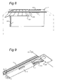
- Figure 3 shows a detail of the actuator of Figure 1 at the end of the profile section and with the pull relief 5. It can be seen clearly here how the movement unit 2 is provided at one end with a corner strip 6, which engages in a recessed part of the pull relief 5.
- Figure 4 is an exploded view of a part of the section 1, in particular the cable duct 3, which is co-moulded integrally with the extruded section, the pull relief 5 and also the coiled cable 4.
- Part of the shape of pull relief 5 is adapted to the cross section of cable duct 3 so that it can move, i.e. run, through said cable duct, and the pull relief 5 has a part projecting from the cable duct 3.
- the pull relief 5 is composed here of two plastics parts. One of the halves of the pull relief 5 is shown in Figure 5. This half of the pull relief 5 is provided with a pin, which extends in the open heart of the coiled cable. Furthermore, this part is provided with a channel through which a cable end of the coiled cord can be passed for feeding further to the movement unit 2. Said channel is provided with edges here, in order to form a pull relief function.
- Figure 6 shows in detail one end of the movement unit 2 provided with the corner strip 6, which engages in the pull relief 5 provided with the coiled cord 4.
- a magnet opening 11 is also shown here. The vicinity of the magnet, and therefore of the movement unit 2, can be determined by placing a coil in duct 8.
- Figure 7 shows an end cap or end part 12, preferably made of plastic, preferably a plastics end part provided with pull relief as end cap on the extruded aluminium section 1 of the preceding figures.
- Said end part 12 is provided with a pin, which extends partly inside the heart or open core of the coiled cord 3.
- the end part 12 is provided with an inlet part 13, which during fitting connects to duct 8, and into which the cables of sensors of the cable duct 8 can be fed.
- the duct 8, in which the sensors can be fitted also serve here as the cable duct for the cables of said sensors.
- the cables of the sensors and the cable of the coiled cord run through the end cap 12 up to the pull relief 14 and leave the end part 12 together through one outlet at that point.
- the movement unit 2 will be provided with control electronics.
- This control electronics can comprise a send and transmission unit which can send and receive information, and operates for instance via Bluetooth, wifi, or another wireless coupling.
- This allows the control electronics to be read out via a mobile computing device, like a PDA.
- the control electronics inside the movement unit 2 should comprise a counter, a time registration device, a memory.
- cargo space 100 of for instance a lorry is shown which is closed of by means of a sliding door 101.
- the sliding door 101 runs in two rails 102 (only one side is shown).
- the profile section 1 is mounted against the roof of the cargo space 100, and via a coupling 103 the movement unit 2, which is able to run along the profile section 1, is coupled to the sliding door 101 to take is along as it runs along the profile section 1.
- control electronics should be operationally coupled to various sensors described above.
Landscapes
- Power-Operated Mechanisms For Wings (AREA)
Applications Claiming Priority (2)
| Application Number | Priority Date | Filing Date | Title |
|---|---|---|---|
| NL1200177 | 2006-08-11 | ||
| US11/732,510 US7578540B2 (en) | 2006-08-11 | 2007-04-03 | Vehicle sliding door actuator |
Publications (2)
| Publication Number | Publication Date |
|---|---|
| EP1889994A2 true EP1889994A2 (de) | 2008-02-20 |
| EP1889994A3 EP1889994A3 (de) | 2013-09-11 |
Family
ID=38775810
Family Applications (1)
| Application Number | Title | Priority Date | Filing Date |
|---|---|---|---|
| EP20070114239 Withdrawn EP1889994A3 (de) | 2006-08-11 | 2007-08-13 | Aktuator für eine Fahrzeugschiebetür |
Country Status (1)
| Country | Link |
|---|---|
| EP (1) | EP1889994A3 (de) |
Cited By (1)
| Publication number | Priority date | Publication date | Assignee | Title |
|---|---|---|---|---|
| WO2024057055A1 (en) * | 2022-09-18 | 2024-03-21 | Houtveen Beheer Achterveld B.V. | A device for operating a rolling door, a method for operating a rolling door, a storage room and a truck |
Citations (4)
| Publication number | Priority date | Publication date | Assignee | Title |
|---|---|---|---|---|
| US5536061A (en) * | 1994-12-05 | 1996-07-16 | Chrysler Corporation | Automotive vehicle body with powered sliding side door |
| DE10005103A1 (de) * | 1999-02-10 | 2000-09-14 | Wilhelm Rademacher | Antriebsvorrichtung für ein Tor o. dgl. insbesondere Garagentorantrieb |
| EP1053380A1 (de) * | 1998-02-06 | 2000-11-22 | Sommer GmbH, mechanische Fertigung | Elektromechanischer garagentorantrieb |
| US6254176B1 (en) * | 1999-09-20 | 2001-07-03 | Meritor Light Vehicle Technology, Llc | Retractable cord mounted in sunroof channel |
-
2007
- 2007-08-13 EP EP20070114239 patent/EP1889994A3/de not_active Withdrawn
Patent Citations (4)
| Publication number | Priority date | Publication date | Assignee | Title |
|---|---|---|---|---|
| US5536061A (en) * | 1994-12-05 | 1996-07-16 | Chrysler Corporation | Automotive vehicle body with powered sliding side door |
| EP1053380A1 (de) * | 1998-02-06 | 2000-11-22 | Sommer GmbH, mechanische Fertigung | Elektromechanischer garagentorantrieb |
| DE10005103A1 (de) * | 1999-02-10 | 2000-09-14 | Wilhelm Rademacher | Antriebsvorrichtung für ein Tor o. dgl. insbesondere Garagentorantrieb |
| US6254176B1 (en) * | 1999-09-20 | 2001-07-03 | Meritor Light Vehicle Technology, Llc | Retractable cord mounted in sunroof channel |
Cited By (1)
| Publication number | Priority date | Publication date | Assignee | Title |
|---|---|---|---|---|
| WO2024057055A1 (en) * | 2022-09-18 | 2024-03-21 | Houtveen Beheer Achterveld B.V. | A device for operating a rolling door, a method for operating a rolling door, a storage room and a truck |
Also Published As
| Publication number | Publication date |
|---|---|
| EP1889994A3 (de) | 2013-09-11 |
Similar Documents
| Publication | Publication Date | Title |
|---|---|---|
| US7578540B2 (en) | Vehicle sliding door actuator | |
| US6539669B1 (en) | Plug door drive system | |
| US9234377B2 (en) | Powered garage door opener | |
| EP0853714B1 (de) | Kraftantrieb für ein beweglichen verschluss mit kugelmutterantriebsspindel | |
| US7159930B2 (en) | Power slide device for vehicle sliding door | |
| CN102561878B (zh) | 用于在具有进入口的车辆中促动多个部件的系统 | |
| EP2020579A2 (de) | Türbetätigungsvorrichtung zur Betätigung der Tür eines Kühl-/Gefrierschrankes | |
| US8464469B2 (en) | Belt driven power sliding door with belt tensioner | |
| US8443866B2 (en) | Methods, apparatuses, and systems for movable partitions | |
| KR19990029094A (ko) | 슬라이딩 벽 | |
| CN103764421B (zh) | 车辆卷帘组件和顶棚组件 | |
| US9446703B1 (en) | Slidable room assembly | |
| CN102733708A (zh) | 尤其用于滑动门且通常用于滑动门或窗关闭元件的线性致动器 | |
| US20140352216A1 (en) | Vehicle doors closer and working unit for a vehicle doors closer | |
| US9003708B2 (en) | Moving body drive apparatus | |
| US6684567B2 (en) | Plug door drive system | |
| US20040020612A1 (en) | Ceiling actuator for up-and-over and sectional doors | |
| EP1889994A2 (de) | Aktuator für eine Fahrzeugschiebetür | |
| CN101802336A (zh) | 用于机动地调节汽车门或类似物的驱动装置 | |
| US8276316B2 (en) | Sliding door device | |
| US20080083167A1 (en) | Chain guide insert for a garage door | |
| DE102008020285A1 (de) | Antrieb für Schubladen oder dergleichen | |
| WO2009138518A3 (fr) | Dispositif d'obturation d'une baie menagee dans un vehicule automobile, pavillon et vehicule correspondants | |
| CN108222807B (zh) | 一种丝杆传动的两级伸缩屏蔽门 | |
| CN113279653B (zh) | 内移门的开关门装置及开关门控制方法和门体组件 |
Legal Events
| Date | Code | Title | Description |
|---|---|---|---|
| PUAI | Public reference made under article 153(3) epc to a published international application that has entered the european phase |
Free format text: ORIGINAL CODE: 0009012 |
|
| AK | Designated contracting states |
Kind code of ref document: A2 Designated state(s): AT BE BG CH CY CZ DE DK EE ES FI FR GB GR HU IE IS IT LI LT LU LV MC MT NL PL PT RO SE SI SK TR |
|
| AX | Request for extension of the european patent |
Extension state: AL BA HR MK YU |
|
| 111Z | Information provided on other rights and legal means of execution |
Free format text: AT BE BG CH CY CZ DE DK EE ES FI FR GB GR HU IE IS IT LT LU LV MC MT NL PL PT RO SE SI SK TR Effective date: 20130610 |
|
| PUAL | Search report despatched |
Free format text: ORIGINAL CODE: 0009013 |
|
| AK | Designated contracting states |
Kind code of ref document: A3 Designated state(s): AT BE BG CH CY CZ DE DK EE ES FI FR GB GR HU IE IS IT LI LT LU LV MC MT NL PL PT RO SE SI SK TR |
|
| AX | Request for extension of the european patent |
Extension state: AL BA HR MK RS |
|
| RIC1 | Information provided on ipc code assigned before grant |
Ipc: E05F 15/14 20060101ALI20130808BHEP Ipc: E05F 15/16 20060101AFI20130808BHEP |
|
| 17P | Request for examination filed |
Effective date: 20140311 |
|
| RBV | Designated contracting states (corrected) |
Designated state(s): AT BE BG CH CY CZ DE DK EE ES FI FR GB GR HU IE IS IT LI LT LU LV MC MT NL PL PT RO SE SI SK TR |
|
| AKX | Designation fees paid |
Designated state(s): AT BE BG CH CY CZ DE DK EE ES FI FR GB GR HU IE IS IT LI LT LU LV MC MT NL PL PT RO SE SI SK TR |
|
| 17Q | First examination report despatched |
Effective date: 20150508 |
|
| STAA | Information on the status of an ep patent application or granted ep patent |
Free format text: STATUS: THE APPLICATION IS DEEMED TO BE WITHDRAWN |
|
| 18D | Application deemed to be withdrawn |
Effective date: 20170301 |