EP1889697A2 - Unité de sciage et machine de sciage - Google Patents
Unité de sciage et machine de sciage Download PDFInfo
- Publication number
- EP1889697A2 EP1889697A2 EP20070016129 EP07016129A EP1889697A2 EP 1889697 A2 EP1889697 A2 EP 1889697A2 EP 20070016129 EP20070016129 EP 20070016129 EP 07016129 A EP07016129 A EP 07016129A EP 1889697 A2 EP1889697 A2 EP 1889697A2
- Authority
- EP
- European Patent Office
- Prior art keywords
- saw
- sawing
- unit
- sawing machine
- machine unit
- Prior art date
- Legal status (The legal status is an assumption and is not a legal conclusion. Google has not performed a legal analysis and makes no representation as to the accuracy of the status listed.)
- Withdrawn
Links
- 239000000463 material Substances 0.000 claims description 59
- 238000003801 milling Methods 0.000 claims description 23
- 238000012545 processing Methods 0.000 claims description 14
- 239000000758 substrate Substances 0.000 claims description 6
- 241000345998 Calamus manan Species 0.000 claims description 5
- 230000000712 assembly Effects 0.000 claims description 5
- 238000000429 assembly Methods 0.000 claims description 5
- 238000000034 method Methods 0.000 claims description 5
- 235000012950 rattan cane Nutrition 0.000 claims description 5
- 230000008569 process Effects 0.000 claims description 4
- 230000000284 resting effect Effects 0.000 claims description 3
- 230000004044 response Effects 0.000 claims description 2
- 230000032258 transport Effects 0.000 description 11
- 238000010276 construction Methods 0.000 description 8
- 238000005520 cutting process Methods 0.000 description 8
- 238000011144 upstream manufacturing Methods 0.000 description 8
- 238000000605 extraction Methods 0.000 description 7
- 238000013461 design Methods 0.000 description 4
- 238000006073 displacement reaction Methods 0.000 description 4
- 230000002349 favourable effect Effects 0.000 description 4
- 230000005540 biological transmission Effects 0.000 description 3
- 238000013016 damping Methods 0.000 description 3
- 239000002023 wood Substances 0.000 description 3
- 230000008901 benefit Effects 0.000 description 2
- 238000012423 maintenance Methods 0.000 description 2
- 230000013011 mating Effects 0.000 description 2
- 238000003860 storage Methods 0.000 description 2
- 230000006978 adaptation Effects 0.000 description 1
- 238000013459 approach Methods 0.000 description 1
- 239000000969 carrier Substances 0.000 description 1
- 230000008859 change Effects 0.000 description 1
- 238000004140 cleaning Methods 0.000 description 1
- 238000011109 contamination Methods 0.000 description 1
- 238000009434 installation Methods 0.000 description 1
- 230000004048 modification Effects 0.000 description 1
- 238000012986 modification Methods 0.000 description 1
- 230000000149 penetrating effect Effects 0.000 description 1
- 239000002994 raw material Substances 0.000 description 1
- 238000005096 rolling process Methods 0.000 description 1
- 238000000926 separation method Methods 0.000 description 1
- 239000000725 suspension Substances 0.000 description 1
Images


Classifications
-
- B—PERFORMING OPERATIONS; TRANSPORTING
- B27—WORKING OR PRESERVING WOOD OR SIMILAR MATERIAL; NAILING OR STAPLING MACHINES IN GENERAL
- B27B—SAWS FOR WOOD OR SIMILAR MATERIAL; COMPONENTS OR ACCESSORIES THEREFOR
- B27B7/00—Sawing machines working with circular saw blades, specially designed for length sawing of trunks
- B27B7/04—Sawing machines working with circular saw blades, specially designed for length sawing of trunks by making use of a plurality of circular saws mounted on a single spindle; Arrangements for adjusting the mutual distances
-
- B—PERFORMING OPERATIONS; TRANSPORTING
- B23—MACHINE TOOLS; METAL-WORKING NOT OTHERWISE PROVIDED FOR
- B23D—PLANING; SLOTTING; SHEARING; BROACHING; SAWING; FILING; SCRAPING; LIKE OPERATIONS FOR WORKING METAL BY REMOVING MATERIAL, NOT OTHERWISE PROVIDED FOR
- B23D47/00—Sawing machines or sawing devices working with circular saw blades, characterised only by constructional features of particular parts
- B23D47/02—Sawing machines or sawing devices working with circular saw blades, characterised only by constructional features of particular parts of frames; of guiding arrangements for work-table or saw-carrier
Definitions
- the present invention relates to a sawing machine unit for a sawing material moved along a feed path in the feed direction in a sawing machine processing successive sawing machine units of this type.
- the shegemaschinentician comprises a machine frame and at least one on the machine frame in fixed spatial allocation to the same attached tool assembly which is designed such that it processes the tooling on the Wekzeugan Aunt in the feed direction V over transported sawing material and / or transported the sawing material in the feed direction V centered for further transport.
- Fixed spatial allocation is intended to mean that the tool arrangement is movable relative to the machine frame essentially neither in the feed direction nor in one direction in a plane transverse to the feed direction.
- the individual sawing machine units in particular sawing units, milling units, planing units and the like, are arranged successively.
- a sawing machine unit configured as a draw-in unit may be connected in front of a respective one of the said sawing machine units and / or a sawing machine unit designed as a pull-out unit can be used, which ensure a correct transport of the sawed goods through appropriate transport and / or positioning arrangements (eg rollers or roller units).
- the respective shegemaschinenticianen are thus arranged in a fixed assignment to the respective preceding or subsequent sawing machine unit.
- the tool assembly is mounted in such a shegemaschinenech at an appropriate position on the machine frame, which, as well as the saw machine unit preceding or following Sawing machine units, standing firmly on a ground.
- the tool assembly held on the machine frame eg, a saw assembly comprising a saw shaft with saw blade assembly disposed thereon, is movable relative to the machine frame, eg, height adjustable (eg, to set different heights for the saw axis).
- height adjustable eg, to set different heights for the saw axis.
- the DE 198 35 138 A1 and the DE 43 11 582 C1 are sawing arrangements for cutting of sawing material, which is transported along a feed direction known.
- a sawing arrangement is provided with a saw axis parallel to the feed direction of the shegeguts.
- the sawing arrangement is held movable on a machine frame in two directions transversely to the feed direction.
- the machine frame can according to DE 43 11 582 C1 be moved in the feed direction with the sawing material to allow cutting to length with undiminished further transport of the sawing material.
- the object of the invention is to provide a drillgemaschinetician for a sawing machine of the type mentioned, the improved flexibility in construction and operation offers. Another object is to provide a sawing machine of the type mentioned, which is easier to install and easier to maintain.
- the machine frame has a guide arrangement, by which it at one immediately in the feed direction and / or immediately following shegemaschinentician sawing machine along at least one transverse to the feed direction guide movable is.
- the guide can be a guide in the vertical direction or a guide in a transverse direction to the feed direction (in particular orthogonal to the feed direction) extending horizontal direction.
- a respective guide arrangement is provided, which allows a guide in the vertical direction and a guide in the horizontal direction transverse to the feed direction. If necessary.
- a single leadership arrangement is in question, which allows a movement in both directions.
- the adjustment can also do in a few steps, the tool assembly can be firmly pre-assembled on the machine frame.
- the guide on the preceding or / and subsequent sawing machine unit allows exact adjustment possibilities even with great weight of the sawing machine unit, because the adjustment directions are predetermined by the guide tracks.
- the benchgemaschinentician can be compact, since within the adjustable frame, the complete tool assembly or optionally more tool arrangements can be firmly attached. At the same time, this creates more free space that can be used to arrange drive motors for the tool arrangement (s) in a variable manner depending on the most favorable conditions.
- the sawing machine unit immediately preceding or / and immediately following in the feed direction may e.g. a guide unit for the sawmill, i. be a feed unit or pull-out unit for the sawgemaschinentician or be a downstream of a sawing machine unit downstream extraction unit. It can u. Also, a sawing machine unit pretreating or further processing the sawing material, e.g. an upstream or downstream milling unit, planing unit, sideboard separation unit or saw unit, be.
- the tool assembly may only have one tool attached to a tool shaft extending along a tool axis of rotation, e.g. Saw blade, or several tools, e.g. Saw blades, comprise, which are mounted on the tool shaft as a tool assembly together around the tool axis rotatable at a distance in the axial direction to each other.
- the tool shaft can be mounted on both sides of a feed path of the sawing material or only on one side.
- the benchgemaschinentician or the machine frame can be suspended on a resting on a substrate frame of a sawing machine. It is even possible to dispense with a separate frame when the sawing machine unit or the machine frame is suspended from the sawing machine unit which is located immediately preceding and / or immediately following in the feed direction. In both cases, the machine frame is not itself on the ground, but is connected to this only on the frame or the frame or the feet of the corresponding immediately preceding and / or immediately following sawing machine unit (s). With such a hanging sawing machine unit, it hardly matters whether the ground beneath the sawing machine unit is flat or uneven in itself.
- the downgemaschinentician can on the one hand in the manner of a protruding ridge on the immediately preceding or / and immediately following arranged shegemaschineaji hang freely or in the manner of a Bridge between the immediately preceding and / or immediately following sawing machine unit arranged.
- a suitable design of the guide can be easily achieved that they can carry the weight of the complete shegemaschinentician and beyond can also be easily adjusted.
- the machine frame can have at its front or / and rear side in the feed direction a linear guide arrangement cooperating with the immediately preceding and / or immediately following sawing machine unit.
- a rail system is mounted, which cooperates with a corresponding carriage assembly which is attached to the immediately preceding and / or immediately following sawgemaschinentician cooperates, or conversely, a carriage assembly on the machine frame of shegemaschinentician is provided with a corresponding rail system, which at the immediately preceding or / and immediately following sawing machine unit is mounted, cooperates.
- the linear guide system can be a sliding guide in the simplest case.
- the machine frame for example, in the case of a saw unit with the attached thereto sawing arrangement (s), is very difficult, it will be advisable to use correspondingly more elaborate liner guide systems, in which the carriage is supported by rolling elements.
- the guide permits the machine frame to be moved relative to the sawing machine unit immediately preceding and / or immediately following movement relative to the guide direction, i. in particular transversely to the feed direction, at least temporarily to lock.
- certain preferred operating positions can be approached quickly and always the same.
- the guide arrangement essentially in an upper region of the machine frame, in particular substantially above the tool arrangement or at the same height as this is arranged, because then the risk of contamination of the guide assembly, for example by falling down in operation wood chips and the like., Is reduced. This is particularly true for horizontally extending guide assemblies, which can be easily moved into an area that lies above and outside the tool assembly. However, it is also desirable in other course of the guide direction to arrange as large a part of the guide assembly above the tool assembly.
- One of the at least one tool assembly associated drive motor can be conveniently mounted on the top of the machine frame.
- An automatic adjustment can be realized in a simple manner by providing an interacting with the machine frame for adjusting the machine frame transverse to the feed direction of the sawing material actuator.
- the adjusting device will in this case be designed as a low-cost linear drive device and may be hydraulically, pneumatically or mechanically actuated. Examples of such linear drive device are hydraulically or pneumatically actuated cylinder / piston units or spindle / slide drives.
- the adjusting device can be arranged in a simple manner between the machine frame and a substrate on which the sawing machine, and thus serve to raise or lower the machine frame, but also produce a displacement of the machine frame parallel to the ground.
- the actuator will attack in this case on the underside of the machine frame.
- the adjusting device can also be arranged between the machine frame and the frame and attack for example on the top of the machine frame or laterally on the machine frame. It goes without saying that a combination of these possibilities is also conceivable.
- Such a method is particularly useful in a sawing unit as an example of the sawing machine unit, when an adjustability of the machine frame in both the direction of the saw axis (s) and orthogonal to the saw axis (s) is desired.
- the guidance of the machine frame on a sawgemaschinenech the preceding and / or subsequently arranged sawing machine unit also allows damping of vibrations caused by vibrations generated in other Sawing machine units.
- the influence of such vibrations, which are generated by the sawing machine units directly coupled to the sawing machine unit, for example draw-in or pull-out devices, can be suppressed on the sawing machine unit.
- the machine frame executes displacement movements in response to movements, in particular vibrations, of the saw machine unit preceding and / or subsequently arranged, which compensate for these vibrations or vibrations.
- the benchgemaschineü can be formed, for example, as a saw unit, wherein a sawing arrangement with at least one saw blade about an associated relative to the machine frame - at least during operation - both in the feed direction and in the direction of a plane transverse to the feed direction fixed saw axis is rotatable and from one side of the Saw good in this shegegut engages.
- the saw axis of the saw unit preferably extends transversely to the feed direction.
- the saw blade or the saw blade arrangement then generates sawing material in the sawing material, viewed in the longitudinal direction of the sawing material, preferably either as a horizontal cutting surface with a vertically arranged sawing axis or as a vertical cutting surface with a horizontally arranged sawing axis.
- the machine frame is guided on the immediately preceding and / or immediately following drillgemaschinenech displaced in a direction substantially orthogonal to the saw axis.
- Such a displacement of the machine frame allows for one and the same sawing arrangement, the cutting of the saw blade into the sawing material from two opposite sides of the sawgeguts ago.
- the same sawing arrangement both in synchronism, ie in the same direction rotation of the saw blade with the feed direction of the shegguts, as well as in the opposite direction, ie in opposite directions rotation of the saw blade to the feed direction of the shegeguts work.
- the machine frame is displaced in the vertical direction, which makes it possible to make an incision in the sawing material for a bottom and the other after adjusting the machine frame upwards from above.
- the vertical adjustment height can be up to several meters, so that, for example, between a height of the saw axis between 18 and 100 mm can be sawn from the bottom in the opposite direction and sawn from a height of the saw axis of 100 mm from above in synchronism.
- it allows the present invention provided leadership of the machine frame to move this quickly and flexibly between different positions without having to make any new fine adjustment.
- the machine frame can alternatively or in addition to the adjustment mentioned orthogonal to the saw axis on the immediately preceding and / or immediately following shegemaschinentician be guided displaced in the direction of the saw axis substantially. If the saw axis runs horizontally, this means an adjustment of the machine frame in the transverse direction to the feed direction. Then you can make cuts in the sawing material with vertically arranged saw blades at different width positions or horizontally arranged saw blades at different heights.
- a particularly favorable and flexible use of the saw unit can be achieved if at least two saw blade rattan arrangements are mounted on the saw axis, which have such a distance to each other in the axial direction of the saw axis that by moving the machine frame in the direction of the saw axis alternately one of the polegeblattanssenen in a sawing can be brought, in which their saw blades can engage in the sawing material.
- Sawing here is to be understood as a displacement of the corresponding saw blade arrangement into the region of the feed path of the sawed material. If the saw axis runs transversely to the feed direction, an adjustment in the direction of the saw axis is equivalent to an adjustment in the transverse direction to the feed direction.
- the guidance of the machine frame makes it possible to bring the saw blade rattan alternately in a short time in shege ein. Larger fine adjustments are usually superfluous.
- the guide has corresponding locking devices, which ensure that the guide is at least temporarily locked or latched when reaching the sawing position of one of the saw blade rattan arrangements.
- Each saw blade assembly in this preferred embodiment comprises at least one saw blade, e.g. each has a different thickness, radius and / or / and toothing, so that the saw unit can be flexibly adapted for different shegegut.
- each saw blade assembly comprises at least two saw blades at different distances from each other.
- the saw blade racks can have saw blades with different distances from one another, so that different board thicknesses can be sawn by simply pushing the machine frame back and forth.
- the saw arrangement can have as a single-shaft saw only a single saw axis running essentially orthogonally to the feed direction. Even then you get because of the various adjustment of the machine frame already flexible sawing unit that can work both in synchronism and in the opposite direction and beyond can produce a variety of patterns without structural changes are required.
- the sawing arrangement may also comprise two sawing axes, which are generally substantially orthogonal to the feed direction, the second sawing axis being a counter sawing axis associated with a second sawing blade of the side of the sawed object opposite one side engages in this sawing material.
- the saw blade associated with a saw axis and the saw blade associated with the associated counter saw axis can, relative to the feed direction of the sawing material, be arranged at substantially the same transverse position. If you want to use different sized saw blades, it may for example be thought to provide each correspondingly provided mounting positions for at least one of the saw shafts, each mounting position is selected such that a matched to the size of the respective saw blade distance between the saw shafts is maintained. Alternatively, a separate machine frame can be provided for each saw shaft, so that the distance between the saw shafts can be adjusted by displacing the machine frames along their respective guide arrangements.
- the flexibility of the arrangement of the machine frame makes it possible to fix the at least one saw blade along its associated saw axis without losing a substantial part of the flexibility.
- one of the at least one saw axis associated drive motor may be attached. If a plurality of saw axes are present, it is possible, if appropriate, for each saw axis to be assigned a separate drive motor and accordingly attached to the machine frame. Since the machine frame is not freely displaced, but only along predetermined guide directions, the ever increasing weight does not affect a sufficiently precise adjustment of the machine frame not too strong.
- the drive motor may be mounted on the top of the machine frame.
- the drive motor can also drive the saw shafts of two saw assemblies, each of which has a substantially orthogonal to the feed direction shegeeachse. He can do this via a suitable transmission, e.g. a belt transmission to be coupled to the respective saw shafts.
- the sawing machine unit can be designed as a vertical saw unit, the sawing arrangement being such that the sawing axis runs horizontally.
- the sawing machine unit can also be used as a horizontal sawing machine unit be formed, wherein the sawing arrangement is formed such that the saw axis extends vertically.
- the shegemaschinentician can be formed as a horizontal or vertical milling unit, which has a tool assembly comprising at least one milling head, preferably a milling head or two milling heads at a distance from each other. Another possibility is to form the shegemaschinentician as Veryware-Abtragaggregat.
- the sawing machine unit is also possible to form the sawing machine unit as a planing unit with at least one planer shaft.
- the sawing machine unit it is conceivable to design the sawing machine unit as a side-processing unit, ie for processing the side surfaces of the sawed material before or after the actual sawing process.
- the invention relates in addition to the sawgemaschinentician described also on a sawing machine, in which at least one sawing machine unit of the type described is installed.
- the sawing machine unit arranged immediately below can be a pull-out device downstream of the sawing machine unit for the sawing material leaving the sawing machine unit.
- the extension device then has a guide arrangement cooperating with the guide arrangement on the machine frame.
- the previously arranged sawing machine unit may be a feed device for the sawing material arranged in the feed direction in front of the sawing machine unit, which has a guide arrangement cooperating with the guide arrangement on the machine frame of the sawing machine unit.
- a feed unit for the SAgemaschinenhim but can also be provided as the previously arranged SAgemaschinentician a pull-out device of an upstream further sawing machine unit.
- the sawing machine constructed in this way has a modular structure consisting of individual sawing machine units which are self-standing work.
- Each of the shegemaschineüticianen can be pre-assembled in a simple manner, since it is usually not necessary to store individual components of the respective shegemaschinenech movable relative to the respective machine frame. Rather, the individual shegemaschinentician - apart from the always required rotational mobility, for example, a saw blade relative to the machine frame once - be constructed as a substantially inherently rigid construction.
- the sawing machine of modular design in such a manner can nevertheless be adapted in an extremely simple manner to a wide variety of circumstances by combining different sawing machine units, which are guided on the respective sawing machine unit upstream or downstream of them, depending on the desired functionality.
- these shegemaschinenticianen are not stored directly on the ground, but are rather stored in a free-floating or hanging manner on their respective associated upstream and / or downstream sawing machine unit or a fixed frame of the sawing machine.
- the contact with a substrate happens here either via the stationary frame of the sawing machine resting on firm foundations or preferably over the individual shegemaschinenticianen which make a processing of SAgeguts, respectively upstream and / or downstream feed units or / and pull-out units.
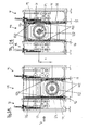
- a first embodiment of a splitgemaschinenhim invention is shown in side view, in Fig. 1A with vertically located in a lowermost position machine frame 16 and in Fig. 1B with vertically upwardly adjusted machine frame 16.
- the saw unit 10 is immediately following a pull-out device 12 is arranged, which in the saw unit 10 carries separated sawing material out of the saw unit 10 and transports it for further processing to subsequent sawing machine units, not shown in FIG.
- the transport rollers 20 used for the transport of the SAgeguts with horizontal axis of rotation of the extension device 12 are shown only schematically.
- the sawing material not shown in FIGS. 1A and 1B is transported in the feed direction V by the sawing machine and the sawing unit 10 of one of these previously arranged collection device 14 with rollers with a vertical axis of rotation (which are also indicated only schematically in FIGS. 1A and 1B). fed.
- the sawing material moves in the feed direction V along its feed path and finally reaches a region in which a in Fig. 1A below Saw saw arranged saw blade 22 of the saw unit 10 can attach cuts in the sawing material.
- 1A and 1B is mounted on a saw shaft 26 running transversely (and orthogonally) to the feed direction V and substantially in the horizontal direction and thus forms cuts in the saw material parallel to the feed direction V.
- the straight line passing through the saw shaft 26 defines a saw axis 24 about which the circular saw blade 22 rotates counterclockwise in FIGS. 1A and 1B (see the corresponding arrow).
- the circular saw blade 22 engages with its lower side into the sawing material and thus operates counterclockwise in a synchronizing arrangement with the saw blade 22 Saw good in which the direction of movement of the engaging in the shegegut section of the saw blade 22 is in the same direction to the feed direction V.
- the same sawing arrangement formed from the saw shaft and the saw blade or saw blade arrangement attached thereto can be used both for cutting saw material in synchronism and in the opposite direction.
- Both the extension device 12 and the collection device 14 are in cross-section double-T-shaped foot parts 28, which rest on a not shown in Fig. 1A and 1 B substrate.
- a frame 30 of the sawing machine In the area of the saw unit 10 is a frame 30 of the sawing machine, which also on such foot parts 28 rests.
- the machine frame 16 is not held on the frame 30 itself, but suspended on a linear guide assembly 32 on the saw unit 10 subsequent extraction device 12.
- the linear guide arrangement 32 comprises two carriages 34, which are mounted at a distance from one another on the machine frame 16 and which are mounted so as to be displaceable in the vertical direction on a rail 36 which is provided on a frame of the pull-out device 12.
- the slides 34 can also be locked by a locking device in a desired vertical position on the linear guide rail 36 (in Fig. 1A and 1B, this locking device is not shown in detail).
- the machine frame 16 of the saw unit 10 is arranged freely relative to the intake device 14. It is thus held and guided only on its immediately following shegemaschinentician, namely the pullout device 12 and is free with its seen in the feed direction V front side.
- the collection device 14 and the saw unit 10 and extractor 12 existing unit are thus decoupled from each other.
- Fig. 1 also still the height offset H between the positions shown in Fig. 1A and 1 B positions of the saw axis 24 is indicated by a double arrow.
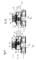
- FIGS. 2A and 2B show a further embodiment of the sawing machine unit according to the invention in the form of a saw unit 110, which, unlike the saw unit 10 shown in FIGS. 1A and 1B, not only on the pull-out device 12 following it, but also on its in Feed direction V of the sawing material preceding functional unit, in this case a further extension device 12 is guided by a respective linear guide device 132 movable.
- the remaining components and the construction of the saw unit 110 correspond to those of the saw unit 10, so that in the following a detailed description of this the same components is omitted and instead reference is made to the corresponding description of these components with respect to FIGS. 1A and 1B.
- components of the saw unit 110 which correspond to components of the saw unit 10 are each designated by the same reference numerals, increased by 100.
- the sawing unit 110 is both at the feed in advance V arranged extending extractor 12 (which may be, for example, the extractor of a previous further Sgemaschinenech not shown) and at the subsequently arranged pullout device 12 like a bridge suspended and guided in the vertical direction up and down arbitrarily adjustable.
- This suspension both at its front in the feed direction V and rear allows a largely balanced support of the carriage 134 on the respective longitudinal guide rail 136, which are attached to the extension devices 12 respectively on the rear and front side.
- the carriages 134 movable along the guide rails 136 are mounted on the machine frame 116.
- the guide rails 136 are formed as rods and the carriage members 134 have these rods encompassing lugs.
- the machine frame 116 has in each case two carriage elements arranged one behind the other in the longitudinal direction of the guide rail 136 with sufficient spacing in order to avoid tilting.
- FIGS. 3A and 1B show a further embodiment of a sawing machine unit according to the invention in the form of a further sawing unit 210 in a side view corresponding to FIGS. 1A and 1B.
- the sawing unit 210 shown in FIGS. 3A and 3B largely corresponds to that in FIGS. 1A and 1
- only those elements of the embodiment shown in FIGS. 3A and 3B are compared with those of FIGS previous embodiments are different.
- Regarding the rest Elements will refer to the description of the previous embodiments.
- the saw unit 210 is designed as a double-shaft saw with two sawing arrangements arranged vertically one above the other.
- Each saw assembly comprises a saw shaft 226 extending horizontally and substantially orthogonal to the feed direction V and extending along a respective saw axis 224.
- a respective circular saw blade 222 is attached at each saw shaft 226, a respective circular saw blade 222 is attached.
- the circular saw blades 222, seen in the transverse direction to the feed direction V are arranged approximately at the same height and bring into the sawing material from each of the lower and the upper side of the shegeguts forth penetrating a common cutting surface.
- the two saw shafts 226 are in this case both driven in the counterclockwise direction, so that the lower circular saw blade 226 works in the mating with the sawed by the saw unit 210 transported sawmill and the upper circular saw blade 226 works in synchronism with the transported by the saw unit 210 sawing material.
- Each of the two saw shafts 226 is associated with a drive motor, not shown in FIGS. 3A and 3B, which is also fastened to the machine frame 216.
- both saw shafts 226 could be driven by a common drive motor.
- the guide of the machine frame 116 of the saw unit 210 on the saw unit subsequent extension device 12 is carried out as in the embodiment Figs. 1A and 1B by a mounted on the front in the feed direction of the pull-out device guide rail 236 and two guided by this guide rail carriage elements 234, respectively are mounted near the upper and lower ends of the machine frame 216.
- the machine unit 216 is guided on its front side in the feed direction on the previously arranged feed device 14 by a further linear guide device 232, which in this case another attached to a frame of the feeder 14
- Linear guide rail 236 and a guided through the linear guide rail 236 carriage member 234 includes.
- the carriage element 234 is mounted in the vicinity of the lower end of the machine frame 216, so that the linear guide rail 236 does not have to extend to the full height of the intake device 14, but already ends below the height of the feed path of the sawing material.
- the three carriage elements 234 guide the machine frame with the two saw assemblies attached thereto at three points, which in the side view according to FIGS. 3A and 3B form a right-angled triangle with each other, so that a sufficiently stable bearing results, in particular a tilting of the carriage elements sufficiently prevented at the respective rail guide.
- an adjusting device 240 is provided in the saw unit 210, which is composed of a cylinder member 242 and a reciprocating member 244.
- the cylinder member 242 is attached to a bottom plate 246, which in turn rests on the foot parts 28.
- the piston member 244 is movable upwardly relative to the cylinder member 242, which is best seen in Figure 3B, which shows a position of the machine frame 216 in which the reciprocating member 244 is extended to move the machine frame 216 upwardly to its highest position is.
- the Hubkolbenelement 244 in turn abuts with its upper end on the underside of the machine frame 216 in order to shift this upwards or downwards.
- the adjusting device 240 can be used to adjust the vertical position of the machine frame 216 to the height of the sawing material to be processed, so that the two circular saw blades 222 each cut equally deep into the sawing material from above and from below.
- the height adjustment of the machine frame 216 can also be such that in each case only the upper and lower circular saw blade 222 comes into engagement with the sawing material, so that this is sawn either only in synchronism or only in the opposite direction.
- the actuator 240 may be e.g. be designed as a simple spring element which extends with a predetermined extension force and the machine frame 216 moves upward until it is locked by a predetermined height locking means (not shown) to assume a predetermined vertical position.
- the adjusting device 240 may also be designed as an actively driven piston-cylinder unit or as a spindle drive which is driven either by hand or by a drive motor in order to respectively approach a predetermined extended position.
- the adjusting device 240 may additionally be provided with suitable damping arrangements, so that it performs suitable compensating movements during vibrations which are transmitted by the feed device 14 and / or the pull-out device 12 to the saw unit 210, and at the same time damps them, to prevent these vibrations from being transmitted to the saw unit 210.
- FIGS. 1 to 3 Although only one single circular saw blade can be seen in the side view according to FIGS. 1 to 3, it is understood that a saw blade arrangement consisting of a plurality of circular saw blades, which are arranged axially apart from one another, can be attached to the respective saw shafts just as well, for example Cut out boards.
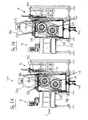
- FIGS. 4 and 5 each show an embodiment of the sawing unit in which the machine frame is displaceable in the horizontal direction transversely to the feed direction V, substantially orthogonal to the feed direction V and in the longitudinal direction of the saw axis of the saw arrangement.
- FIGS. 4A and 4B respectively show a plan view of a fourth embodiment of a sawing machine unit according to the invention in the form of a saw unit 310, which is arranged, similar to the saw unit shown in FIGS. 1A and 1B, between a feed device 14 arranged in the advance direction and a subsequent pull-out device 12. Similar to the saw unit shown in FIGS. 1A and 1B, the saw unit 310 is movably guided on the following pull-out device 12 by a linear guide device 332. In contrast to the linear guide unit shown in FIGS. 1A and 1B, however, the linear guide unit 332 now comprises guide rails 336 attached to the pull-out unit 12, which are substantially horizontal and transverse to the feed direction V, i. parallel to the longitudinal direction of the saw axis 224 run. On the machine frame 316 of the saw unit 310 guide slides 334 are mounted, which are guided along the guide rail 336.
- the machine frame 316 is guided by a further linear guide device 332 beyond that on the feed device 14 previously arranged in the feed direction.
- This linear guide device 332 has the same structure as the linear guide device 332 lying opposite it, so that description of these details can be referred to their description.
- this linear guide device 332 arranged on the front side of the machine frame 316 in the feed direction V also comprises a linear guide rail 336 mounted on the draw-in device 14, which runs essentially parallel to the saw axis 324, and two slide elements 234 which are introduced on the machine frame 316 and through the guide rail 336 are performed.
- a drive motor 242 for driving the circular saw blades 322 is arranged in each case.
- the drive motor 342 is also attached to the machine frame 316.
- the output shaft of the drive motor 342 is extended by a saw shaft 326 extending along the saw axis 324, on which a saw blade assembly 322 is mounted, which consists in the embodiment shown in Fig. 4A and 4B of a plurality of parallel to each other and each with the same distance from one another arranged individual circular saw blades.
- This saw blade arrangement brings in the sawing material each extending in the feed direction cuts to divide the sawing material into individual boards.
- the fifth embodiment of a sawing machine unit according to the invention in the form of a saw unit shown in FIGS. 5A and 5B is movably guided in the longitudinal direction of its saw axis 424. It is therefore very similar to this embodiment, so that in the following only differences in the embodiment shown in FIGS. 5A and 5B compared to the embodiment shown in FIGS. 4A and 4B will be discussed and to describe the remaining elements to the description of the embodiment of FIG 4A and 4B, it being again pointed out that in the embodiment shown in FIGS. 5A and 5B, identical or corresponding elements are denoted by the same reference numerals as the embodiment according to FIGS. 4A and 4B, but increased by 100 more than these ,
- the saw unit 410 according to FIGS. 5A and 5B is guided on its rear side in the feed direction by a linear guide device 432 on the extension device 12 following it in the horizontal direction transversely to the feed direction.
- the linear guide device 432 is formed in the case of the saw unit 410 shown in FIGS. 5A and 5B in that two mutually spaced carriage elements 434 are formed on the machine frame 416, each of which surround a linear guide rail 436 attached to the extension device 12.
- the machine frame 416 together with the saw assembly of drive motor 442, saw shaft 426 and saw blade assembly 422, moves between a position where the saw blade assembly is located at the left edge of the saw path Fig. 5A) and a position at which the saw blade assembly 422 is arranged on the right edge of the feed path V (FIG. 5).
- the other elements of the saw unit 410 according to FIGS. 5A and 5B, reference is made to the preceding embodiments.
- FIGS. 6A and 6B show a modified form of the embodiment of a sawing machine unit according to the invention already shown in FIGS. 3A and 3B as a double-shaft saw. Unless special features of the modification shown in FIGS. 6A and 6B are discussed below, reference is made to the description of FIG. 3 for the purpose of the description, and it should be noted that identical elements are designated by the same reference symbols in FIGS. 3A and 3B.
- a common drive motor 260 for both saw shafts 226 of the saw assembly is mounted on top of the machine frame 216.
- the drive motor 260 as a comparison of Fig. 6A with Fig. 6B shows, moved in the vertical adjustment of the machine frame 216 by means of the linear guide device 232.
- To drive the vertical adjustment of the machine frame 216 serves the 6A and 6B in Figures 6A and 6B between the ground on which stands the sawing machine, and the bottom of the machine frame 216 acting actuator 240. Because the two linear guide devices 232 allow precise guidance of the machine frame, the Actuator 240 readily move even large loads such as the machine frame 216 together with the attached two sawing arrangements and even together with the drive motor 260.
- the arrangement of the drive motor on the top of the machine frame 216 is particularly space-saving and ensures excellent space utilization. In addition to the already mentioned precise guidance of the machine frame 216, this arrangement is made possible by the overall compact design of the saw unit, which allows diverse mounting options for the drive motor on the machine frame.
- Another special feature of the drive motor according to FIGS. 6A and 6B is that it has two gear units, preferably designed as belt transmissions, via which it drives both saw shafts 226.
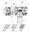
- FIG. 7 shows a top view of a modular sawing machine (100) according to the invention, which comprises a plurality of different embodiments of sawing machine units according to the invention, each with different tool arrangements.
- This sawing machine 100 allows the processing of sawing material, in particular of round logs, Profilkanthölzern, squared timbers and models of the raw material to product finished boards after passing through successively connected sawing machine units 510, 12, 610, 12, 410, 12, 710.
- This carrier machine a plurality of extraction / collection devices 12 with successively arranged vertical and horizontal centering devices 12a, 12b, between each of which different shegemaschinenöen 410, 510, 610, 710 are arranged for the actual processing of shegeguts.
- the sawing machine 100 shown in FIG. 7 is a post-cutting group in which the sawed material first enters a side-processing unit 510 in the feed direction V, for example a chip removal device which lifts the outer bark areas of the wood and processes it into chips or wood chips.
- the sawing material leaving the side processing unit 510 is captured by a first pull-out unit 12 and centered in a vertical direction in a first centering unit 12a and in a horizontal direction in a second centering unit 12b.
- a milling unit 610 is vertically and horizontally movably coupled by linear guides, as previously described with reference to a saw unit.
- the milling unit 610 can therefore be displaced in the horizontal direction orthogonal to the material to be sawed as well as in the vertical direction and ultimately adjusted exactly to the feed path of the sawing material.
- the milling unit 610 comprises two milling heads 612a, 612b, each with a vertically arranged milling head axis 614a, 614b. The sawmill is between transported through the two milling heads.
- the sawed material passes again into an extraction unit 12, where it is vertically or horizontally centered in the manner already described in a corresponding first centering unit 12a and a second centering unit 12b and is transported on to a downstream further sawing machine unit 410.
- the shegemaschinentician 410 corresponds to the construction shown in Fig. 5A and 5B, ie with a fixedly mounted in a machine frame 416 saw assembly of drive motor 442, saw shaft 426 and saw blade assembly 422 and with a linear guide device 432, which the saw unit 410 with her subsequent extraction unit 12 Longitudinal guide rails 436 of the linear guide device 432 movably leads.
- FIGS. 5A and 5B it being further noted that the same reference numerals are used in FIG. 7 for the saw unit 410 and its components as for corresponding components in FIG. 5A.
- any of the saw units shown in FIGS. 1A, 1B through 6A, 6B may be provided.
- the last extension unit 12 is followed in FIG. 7 by another sawing machine unit, namely a horizontal circular saw unit 710 with horizontally mounted saw blade mandrels 722A, 722B (whose saw axes 724a, 724b consequently extend vertically).
- the horizontal circular saw unit 710 is also coupled horizontally and vertically movably with its pull-out device 12 by a linear guide device 732 located at its front side in the feed direction.
- the horizontal circular saw unit 110 can therefore be guided both horizontally and vertically relative to the pull-out unit 132, wherein it is also supported by the upstream pull-out unit 12.
- a planing unit with one or more (in particular two) planing devices can be coupled to the end of the pull-out unit 12 located downstream in the feed direction V.
- FIG. 8 Another variant of a sawing machine according to the invention is shown in FIG.
- the sawed material when being transported in the feed direction V, the sawed material initially passes into a pull-out device 12 in order to be horizontally and vertically centered there and transported further to the subsequent milling unit 810.
- Downstream of the milling unit 810 is a further pull-out unit 12, which is coupled to the milling unit 810 via a linear guide device 832 in a horizontally and vertically movable manner.
- the sawing material is passed with an (unprocessed) side under pressure on the milling head 812, which is rotatable about a vertical axis 814.
- the milling head 810 separates the unprocessed side of the sawed product (see b in FIG. 9D) over the entire height.
- the sawing material is again detected by a downstream extraction device 12, vertical ud centered horizontally and to another, downstream sawing 410th transported further.
- the saw unit 410 corresponds to the sawing unit explained above with reference to FIGS. 5A, 5B and 7, and therefore need not be explained in detail here. It should be noted that the reference numerals of the saw unit 410 used in FIG. 8 correspond to those for the embodiment 5A, 5B.
- the sawing material is further sawn to board goods.
- the subsections resulting from this processing step (see c in FIG. 9C) have different lengths, which are later capped to usable lengths in a corresponding cut-to-length sawing unit.
Landscapes
- Engineering & Computer Science (AREA)
- Mechanical Engineering (AREA)
- Life Sciences & Earth Sciences (AREA)
- Wood Science & Technology (AREA)
- Forests & Forestry (AREA)
- Sawing (AREA)
- Machine Tool Units (AREA)
Applications Claiming Priority (2)
| Application Number | Priority Date | Filing Date | Title |
|---|---|---|---|
| DE200620012508 DE202006012508U1 (de) | 2006-08-16 | 2006-08-16 | Sägeeinheit |
| DE102007022165A DE102007022165A1 (de) | 2006-08-16 | 2007-05-11 | Sägemaschineneinheit und Sägemaschine |
Publications (1)
| Publication Number | Publication Date |
|---|---|
| EP1889697A2 true EP1889697A2 (fr) | 2008-02-20 |
Family
ID=38695535
Family Applications (1)
| Application Number | Title | Priority Date | Filing Date |
|---|---|---|---|
| EP20070016129 Withdrawn EP1889697A2 (fr) | 2006-08-16 | 2007-08-16 | Unité de sciage et machine de sciage |
Country Status (3)
| Country | Link |
|---|---|
| EP (1) | EP1889697A2 (fr) |
| DE (1) | DE102007022165A1 (fr) |
| RU (1) | RU2007131184A (fr) |
-
2007
- 2007-05-11 DE DE102007022165A patent/DE102007022165A1/de not_active Withdrawn
- 2007-08-15 RU RU2007131184/03A patent/RU2007131184A/ru not_active Application Discontinuation
- 2007-08-16 EP EP20070016129 patent/EP1889697A2/fr not_active Withdrawn
Also Published As
| Publication number | Publication date |
|---|---|
| DE102007022165A1 (de) | 2008-02-21 |
| RU2007131184A (ru) | 2009-02-20 |
Similar Documents
| Publication | Publication Date | Title |
|---|---|---|
| AT522434B1 (de) | Regallagersystem mit verbesserter Transportfahrzeug-Hebevorrichtung | |
| EP1281491B1 (fr) | Dispositif et procédé pour travailler des pièces à usiner en bois, plastique ou similaires | |
| EP2008734B1 (fr) | Dispositif de transport destiné au transport de pièces à usiner sur une machine de traitement | |
| EP2865484B1 (fr) | Procédé et dispositif d'usinage de pièces | |
| EP2127829A1 (fr) | Installation de distribution de plaques | |
| EP3515624A1 (fr) | Procédé, machine-outil et outil de découpage pour le découpage continu à course multiple de pièces en forme de plaque | |
| EP2046544B1 (fr) | Dispositif de fabrication et/ou d'usinage de panneaux | |
| EP1657035A1 (fr) | Machine à profiler à deux bouts avec rail de guidage de la pièce et procédé de fabrication de pièces avec ladite machine | |
| DE69201080T2 (de) | Doppelseitig wirkende Druckbalken für eine Schneidmaschine. | |
| EP3112083A1 (fr) | Système de portique d'une machine-outil et machine-outil avec un tel système de portique | |
| EP2666583B1 (fr) | Unité mobile d'une machine-outil ainsi que la machine-outil avec une telle unité mobile | |
| EP2481540B1 (fr) | Dispositif de sciage d'au moins deux pièces usinées sous forme de plaques ou de piles de plaques | |
| EP3632600A1 (fr) | Installation de séparation de plaques | |
| EP2147760B1 (fr) | Centre de répartition de plaques destiné au traitement complet de pièces usinées en forme de plaques, notamment des éléments de meuble | |
| EP3333100A1 (fr) | Dispositif de transport et procédé de transport pour une ligne d'assemblage pourvue d'au moins un emplacement de montage | |
| EP3453488A1 (fr) | Installation d'usinage de plaques | |
| DE29611728U1 (de) | Vorrichtung zum beidseitigen Beschleifen von Steinen | |
| EP1990117A2 (fr) | Unité de sciage et machine de sciage | |
| EP1889697A2 (fr) | Unité de sciage et machine de sciage | |
| DE102007022988B4 (de) | Transportvorrichtung für eine Keilverzinkungsanlage | |
| EP2236232B1 (fr) | Scie mécanique | |
| WO2003004215A1 (fr) | Chaine de montage | |
| EP2185330A1 (fr) | Machine à fraiser sur une face et unité d'alésage à utiliser avec une telle machine | |
| EP0813941B2 (fr) | Machine-outil pour l'usinage de pièces allongées | |
| DE10047385C2 (de) | Verfahren und Vorrichtung zur Bearbeitung von fortlaufend bewegten Werkstücken |
Legal Events
| Date | Code | Title | Description |
|---|---|---|---|
| PUAI | Public reference made under article 153(3) epc to a published international application that has entered the european phase |
Free format text: ORIGINAL CODE: 0009012 |
|
| AK | Designated contracting states |
Kind code of ref document: A2 Designated state(s): AT BE BG CH CY CZ DE DK EE ES FI FR GB GR HU IE IS IT LI LT LU LV MC MT NL PL PT RO SE SI SK TR |
|
| AX | Request for extension of the european patent |
Extension state: AL BA HR MK YU |
|
| STAA | Information on the status of an ep patent application or granted ep patent |
Free format text: STATUS: THE APPLICATION IS DEEMED TO BE WITHDRAWN |
|
| 18D | Application deemed to be withdrawn |
Effective date: 20100610 |