EP1888456B1 - Autothermer reformer - Google Patents
Autothermer reformer Download PDFInfo
- Publication number
- EP1888456B1 EP1888456B1 EP06753228.3A EP06753228A EP1888456B1 EP 1888456 B1 EP1888456 B1 EP 1888456B1 EP 06753228 A EP06753228 A EP 06753228A EP 1888456 B1 EP1888456 B1 EP 1888456B1
- Authority
- EP
- European Patent Office
- Prior art keywords
- heat exchanger
- steam
- carrier gas
- gas mixture
- reformer
- Prior art date
- Legal status (The legal status is an assumption and is not a legal conclusion. Google has not performed a legal analysis and makes no representation as to the accuracy of the status listed.)
- Active
Links
Images

Classifications
-
- B—PERFORMING OPERATIONS; TRANSPORTING
- B01—PHYSICAL OR CHEMICAL PROCESSES OR APPARATUS IN GENERAL
- B01J—CHEMICAL OR PHYSICAL PROCESSES, e.g. CATALYSIS OR COLLOID CHEMISTRY; THEIR RELEVANT APPARATUS
- B01J8/00—Chemical or physical processes in general, conducted in the presence of fluids and solid particles; Apparatus for such processes
- B01J8/02—Chemical or physical processes in general, conducted in the presence of fluids and solid particles; Apparatus for such processes with stationary particles, e.g. in fixed beds
- B01J8/04—Chemical or physical processes in general, conducted in the presence of fluids and solid particles; Apparatus for such processes with stationary particles, e.g. in fixed beds the fluid passing successively through two or more beds
- B01J8/0496—Heating or cooling the reactor
-
- B—PERFORMING OPERATIONS; TRANSPORTING
- B01—PHYSICAL OR CHEMICAL PROCESSES OR APPARATUS IN GENERAL
- B01B—BOILING; BOILING APPARATUS ; EVAPORATION; EVAPORATION APPARATUS
- B01B1/00—Boiling; Boiling apparatus for physical or chemical purposes ; Evaporation in general
- B01B1/005—Evaporation for physical or chemical purposes; Evaporation apparatus therefor, e.g. evaporation of liquids for gas phase reactions
-
- B—PERFORMING OPERATIONS; TRANSPORTING
- B01—PHYSICAL OR CHEMICAL PROCESSES OR APPARATUS IN GENERAL
- B01J—CHEMICAL OR PHYSICAL PROCESSES, e.g. CATALYSIS OR COLLOID CHEMISTRY; THEIR RELEVANT APPARATUS
- B01J12/00—Chemical processes in general for reacting gaseous media with gaseous media; Apparatus specially adapted therefor
- B01J12/007—Chemical processes in general for reacting gaseous media with gaseous media; Apparatus specially adapted therefor in the presence of catalytically active bodies, e.g. porous plates
-
- B—PERFORMING OPERATIONS; TRANSPORTING
- B01—PHYSICAL OR CHEMICAL PROCESSES OR APPARATUS IN GENERAL
- B01J—CHEMICAL OR PHYSICAL PROCESSES, e.g. CATALYSIS OR COLLOID CHEMISTRY; THEIR RELEVANT APPARATUS
- B01J19/00—Chemical, physical or physico-chemical processes in general; Their relevant apparatus
- B01J19/26—Nozzle-type reactors, i.e. the distribution of the initial reactants within the reactor is effected by their introduction or injection through nozzles
-
- B—PERFORMING OPERATIONS; TRANSPORTING
- B01—PHYSICAL OR CHEMICAL PROCESSES OR APPARATUS IN GENERAL
- B01J—CHEMICAL OR PHYSICAL PROCESSES, e.g. CATALYSIS OR COLLOID CHEMISTRY; THEIR RELEVANT APPARATUS
- B01J4/00—Feed or outlet devices; Feed or outlet control devices
- B01J4/001—Feed or outlet devices as such, e.g. feeding tubes
- B01J4/002—Nozzle-type elements
-
- B—PERFORMING OPERATIONS; TRANSPORTING
- B01—PHYSICAL OR CHEMICAL PROCESSES OR APPARATUS IN GENERAL
- B01J—CHEMICAL OR PHYSICAL PROCESSES, e.g. CATALYSIS OR COLLOID CHEMISTRY; THEIR RELEVANT APPARATUS
- B01J8/00—Chemical or physical processes in general, conducted in the presence of fluids and solid particles; Apparatus for such processes
- B01J8/02—Chemical or physical processes in general, conducted in the presence of fluids and solid particles; Apparatus for such processes with stationary particles, e.g. in fixed beds
- B01J8/0278—Feeding reactive fluids
-
- C—CHEMISTRY; METALLURGY
- C01—INORGANIC CHEMISTRY
- C01B—NON-METALLIC ELEMENTS; COMPOUNDS THEREOF; METALLOIDS OR COMPOUNDS THEREOF NOT COVERED BY SUBCLASS C01C
- C01B3/00—Hydrogen; Gaseous mixtures containing hydrogen; Separation of hydrogen from mixtures containing it; Purification of hydrogen; Reversible storage of hydrogen
- C01B3/02—Production of hydrogen; Production of gaseous mixtures containing hydrogen
- C01B3/32—Production of hydrogen; Production of gaseous mixtures containing hydrogen by reaction of gaseous or liquid organic compounds with gasifying agents, e.g. water, carbon dioxide or air
- C01B3/34—Production of hydrogen; Production of gaseous mixtures containing hydrogen by reaction of gaseous or liquid organic compounds with gasifying agents, e.g. water, carbon dioxide or air by reaction of hydrocarbons with gasifying agents
- C01B3/38—Production of hydrogen; Production of gaseous mixtures containing hydrogen by reaction of gaseous or liquid organic compounds with gasifying agents, e.g. water, carbon dioxide or air by reaction of hydrocarbons with gasifying agents using catalysts
- C01B3/382—Processes with two or more reaction steps, of which at least one is catalytic, e.g. steam reforming and partial oxidation
-
- B—PERFORMING OPERATIONS; TRANSPORTING
- B01—PHYSICAL OR CHEMICAL PROCESSES OR APPARATUS IN GENERAL
- B01J—CHEMICAL OR PHYSICAL PROCESSES, e.g. CATALYSIS OR COLLOID CHEMISTRY; THEIR RELEVANT APPARATUS
- B01J2208/00—Processes carried out in the presence of solid particles; Reactors therefor
- B01J2208/00008—Controlling the process
- B01J2208/00017—Controlling the temperature
- B01J2208/00106—Controlling the temperature by indirect heat exchange
- B01J2208/00115—Controlling the temperature by indirect heat exchange with heat exchange elements inside the bed of solid particles
- B01J2208/00132—Tubes
-
- B—PERFORMING OPERATIONS; TRANSPORTING
- B01—PHYSICAL OR CHEMICAL PROCESSES OR APPARATUS IN GENERAL
- B01J—CHEMICAL OR PHYSICAL PROCESSES, e.g. CATALYSIS OR COLLOID CHEMISTRY; THEIR RELEVANT APPARATUS
- B01J2208/00—Processes carried out in the presence of solid particles; Reactors therefor
- B01J2208/00008—Controlling the process
- B01J2208/00017—Controlling the temperature
- B01J2208/00106—Controlling the temperature by indirect heat exchange
- B01J2208/00168—Controlling the temperature by indirect heat exchange with heat exchange elements outside the bed of solid particles
- B01J2208/00203—Coils
-
- B—PERFORMING OPERATIONS; TRANSPORTING
- B01—PHYSICAL OR CHEMICAL PROCESSES OR APPARATUS IN GENERAL
- B01J—CHEMICAL OR PHYSICAL PROCESSES, e.g. CATALYSIS OR COLLOID CHEMISTRY; THEIR RELEVANT APPARATUS
- B01J2208/00—Processes carried out in the presence of solid particles; Reactors therefor
- B01J2208/00008—Controlling the process
- B01J2208/00017—Controlling the temperature
- B01J2208/00106—Controlling the temperature by indirect heat exchange
- B01J2208/00309—Controlling the temperature by indirect heat exchange with two or more reactions in heat exchange with each other, such as an endothermic reaction in heat exchange with an exothermic reaction
-
- B—PERFORMING OPERATIONS; TRANSPORTING
- B01—PHYSICAL OR CHEMICAL PROCESSES OR APPARATUS IN GENERAL
- B01J—CHEMICAL OR PHYSICAL PROCESSES, e.g. CATALYSIS OR COLLOID CHEMISTRY; THEIR RELEVANT APPARATUS
- B01J2208/00—Processes carried out in the presence of solid particles; Reactors therefor
- B01J2208/00008—Controlling the process
- B01J2208/00017—Controlling the temperature
- B01J2208/00504—Controlling the temperature by means of a burner
-
- B—PERFORMING OPERATIONS; TRANSPORTING
- B01—PHYSICAL OR CHEMICAL PROCESSES OR APPARATUS IN GENERAL
- B01J—CHEMICAL OR PHYSICAL PROCESSES, e.g. CATALYSIS OR COLLOID CHEMISTRY; THEIR RELEVANT APPARATUS
- B01J2208/00—Processes carried out in the presence of solid particles; Reactors therefor
- B01J2208/00008—Controlling the process
- B01J2208/00017—Controlling the temperature
- B01J2208/0053—Controlling multiple zones along the direction of flow, e.g. pre-heating and after-cooling
-
- B—PERFORMING OPERATIONS; TRANSPORTING
- B01—PHYSICAL OR CHEMICAL PROCESSES OR APPARATUS IN GENERAL
- B01J—CHEMICAL OR PHYSICAL PROCESSES, e.g. CATALYSIS OR COLLOID CHEMISTRY; THEIR RELEVANT APPARATUS
- B01J2208/00—Processes carried out in the presence of solid particles; Reactors therefor
- B01J2208/00008—Controlling the process
- B01J2208/00628—Controlling the composition of the reactive mixture
-
- B—PERFORMING OPERATIONS; TRANSPORTING
- B01—PHYSICAL OR CHEMICAL PROCESSES OR APPARATUS IN GENERAL
- B01J—CHEMICAL OR PHYSICAL PROCESSES, e.g. CATALYSIS OR COLLOID CHEMISTRY; THEIR RELEVANT APPARATUS
- B01J2219/00—Chemical, physical or physico-chemical processes in general; Their relevant apparatus
- B01J2219/00049—Controlling or regulating processes
- B01J2219/00051—Controlling the temperature
- B01J2219/00074—Controlling the temperature by indirect heating or cooling employing heat exchange fluids
- B01J2219/00076—Controlling the temperature by indirect heating or cooling employing heat exchange fluids with heat exchange elements inside the reactor
- B01J2219/00081—Tubes
-
- B—PERFORMING OPERATIONS; TRANSPORTING
- B01—PHYSICAL OR CHEMICAL PROCESSES OR APPARATUS IN GENERAL
- B01J—CHEMICAL OR PHYSICAL PROCESSES, e.g. CATALYSIS OR COLLOID CHEMISTRY; THEIR RELEVANT APPARATUS
- B01J2219/00—Chemical, physical or physico-chemical processes in general; Their relevant apparatus
- B01J2219/00049—Controlling or regulating processes
- B01J2219/00051—Controlling the temperature
- B01J2219/00074—Controlling the temperature by indirect heating or cooling employing heat exchange fluids
- B01J2219/00076—Controlling the temperature by indirect heating or cooling employing heat exchange fluids with heat exchange elements inside the reactor
- B01J2219/00083—Coils
-
- B—PERFORMING OPERATIONS; TRANSPORTING
- B01—PHYSICAL OR CHEMICAL PROCESSES OR APPARATUS IN GENERAL
- B01J—CHEMICAL OR PHYSICAL PROCESSES, e.g. CATALYSIS OR COLLOID CHEMISTRY; THEIR RELEVANT APPARATUS
- B01J2219/00—Chemical, physical or physico-chemical processes in general; Their relevant apparatus
- B01J2219/00049—Controlling or regulating processes
- B01J2219/00051—Controlling the temperature
- B01J2219/00074—Controlling the temperature by indirect heating or cooling employing heat exchange fluids
- B01J2219/00117—Controlling the temperature by indirect heating or cooling employing heat exchange fluids with two or more reactions in heat exchange with each other, such as an endothermic reaction in heat exchange with an exothermic reaction
-
- B—PERFORMING OPERATIONS; TRANSPORTING
- B01—PHYSICAL OR CHEMICAL PROCESSES OR APPARATUS IN GENERAL
- B01J—CHEMICAL OR PHYSICAL PROCESSES, e.g. CATALYSIS OR COLLOID CHEMISTRY; THEIR RELEVANT APPARATUS
- B01J2219/00—Chemical, physical or physico-chemical processes in general; Their relevant apparatus
- B01J2219/00049—Controlling or regulating processes
- B01J2219/00051—Controlling the temperature
- B01J2219/00157—Controlling the temperature by means of a burner
-
- B—PERFORMING OPERATIONS; TRANSPORTING
- B01—PHYSICAL OR CHEMICAL PROCESSES OR APPARATUS IN GENERAL
- B01J—CHEMICAL OR PHYSICAL PROCESSES, e.g. CATALYSIS OR COLLOID CHEMISTRY; THEIR RELEVANT APPARATUS
- B01J2219/00—Chemical, physical or physico-chemical processes in general; Their relevant apparatus
- B01J2219/00049—Controlling or regulating processes
- B01J2219/00051—Controlling the temperature
- B01J2219/00159—Controlling the temperature controlling multiple zones along the direction of flow, e.g. pre-heating and after-cooling
-
- B—PERFORMING OPERATIONS; TRANSPORTING
- B01—PHYSICAL OR CHEMICAL PROCESSES OR APPARATUS IN GENERAL
- B01J—CHEMICAL OR PHYSICAL PROCESSES, e.g. CATALYSIS OR COLLOID CHEMISTRY; THEIR RELEVANT APPARATUS
- B01J2219/00—Chemical, physical or physico-chemical processes in general; Their relevant apparatus
- B01J2219/00049—Controlling or regulating processes
- B01J2219/00186—Controlling or regulating processes controlling the composition of the reactive mixture
-
- C—CHEMISTRY; METALLURGY
- C01—INORGANIC CHEMISTRY
- C01B—NON-METALLIC ELEMENTS; COMPOUNDS THEREOF; METALLOIDS OR COMPOUNDS THEREOF NOT COVERED BY SUBCLASS C01C
- C01B2203/00—Integrated processes for the production of hydrogen or synthesis gas
- C01B2203/02—Processes for making hydrogen or synthesis gas
- C01B2203/0205—Processes for making hydrogen or synthesis gas containing a reforming step
- C01B2203/0227—Processes for making hydrogen or synthesis gas containing a reforming step containing a catalytic reforming step
- C01B2203/0244—Processes for making hydrogen or synthesis gas containing a reforming step containing a catalytic reforming step the reforming step being an autothermal reforming step, e.g. secondary reforming processes
-
- C—CHEMISTRY; METALLURGY
- C01—INORGANIC CHEMISTRY
- C01B—NON-METALLIC ELEMENTS; COMPOUNDS THEREOF; METALLOIDS OR COMPOUNDS THEREOF NOT COVERED BY SUBCLASS C01C
- C01B2203/00—Integrated processes for the production of hydrogen or synthesis gas
- C01B2203/06—Integration with other chemical processes
- C01B2203/066—Integration with other chemical processes with fuel cells
-
- C—CHEMISTRY; METALLURGY
- C01—INORGANIC CHEMISTRY
- C01B—NON-METALLIC ELEMENTS; COMPOUNDS THEREOF; METALLOIDS OR COMPOUNDS THEREOF NOT COVERED BY SUBCLASS C01C
- C01B2203/00—Integrated processes for the production of hydrogen or synthesis gas
- C01B2203/08—Methods of heating or cooling
- C01B2203/0805—Methods of heating the process for making hydrogen or synthesis gas
- C01B2203/0811—Methods of heating the process for making hydrogen or synthesis gas by combustion of fuel
-
- C—CHEMISTRY; METALLURGY
- C01—INORGANIC CHEMISTRY
- C01B—NON-METALLIC ELEMENTS; COMPOUNDS THEREOF; METALLOIDS OR COMPOUNDS THEREOF NOT COVERED BY SUBCLASS C01C
- C01B2203/00—Integrated processes for the production of hydrogen or synthesis gas
- C01B2203/08—Methods of heating or cooling
- C01B2203/0872—Methods of cooling
- C01B2203/0883—Methods of cooling by indirect heat exchange
-
- C—CHEMISTRY; METALLURGY
- C01—INORGANIC CHEMISTRY
- C01B—NON-METALLIC ELEMENTS; COMPOUNDS THEREOF; METALLOIDS OR COMPOUNDS THEREOF NOT COVERED BY SUBCLASS C01C
- C01B2203/00—Integrated processes for the production of hydrogen or synthesis gas
- C01B2203/12—Feeding the process for making hydrogen or synthesis gas
- C01B2203/1276—Mixing of different feed components
-
- C—CHEMISTRY; METALLURGY
- C01—INORGANIC CHEMISTRY
- C01B—NON-METALLIC ELEMENTS; COMPOUNDS THEREOF; METALLOIDS OR COMPOUNDS THEREOF NOT COVERED BY SUBCLASS C01C
- C01B2203/00—Integrated processes for the production of hydrogen or synthesis gas
- C01B2203/14—Details of the flowsheet
- C01B2203/142—At least two reforming, decomposition or partial oxidation steps in series
-
- C—CHEMISTRY; METALLURGY
- C01—INORGANIC CHEMISTRY
- C01B—NON-METALLIC ELEMENTS; COMPOUNDS THEREOF; METALLOIDS OR COMPOUNDS THEREOF NOT COVERED BY SUBCLASS C01C
- C01B2203/00—Integrated processes for the production of hydrogen or synthesis gas
- C01B2203/80—Aspect of integrated processes for the production of hydrogen or synthesis gas not covered by groups C01B2203/02 - C01B2203/1695
- C01B2203/82—Several process steps of C01B2203/02 - C01B2203/08 integrated into a single apparatus
-
- Y—GENERAL TAGGING OF NEW TECHNOLOGICAL DEVELOPMENTS; GENERAL TAGGING OF CROSS-SECTIONAL TECHNOLOGIES SPANNING OVER SEVERAL SECTIONS OF THE IPC; TECHNICAL SUBJECTS COVERED BY FORMER USPC CROSS-REFERENCE ART COLLECTIONS [XRACs] AND DIGESTS
- Y02—TECHNOLOGIES OR APPLICATIONS FOR MITIGATION OR ADAPTATION AGAINST CLIMATE CHANGE
- Y02E—REDUCTION OF GREENHOUSE GAS [GHG] EMISSIONS, RELATED TO ENERGY GENERATION, TRANSMISSION OR DISTRIBUTION
- Y02E60/00—Enabling technologies; Technologies with a potential or indirect contribution to GHG emissions mitigation
- Y02E60/30—Hydrogen technology
- Y02E60/50—Fuel cells
Definitions
- the invention relates to an autothermal reformer for generating a hydrogen-rich gas mixture for use in a fuel cell.
- polymer electrolyte membrane (PEM) fuel cells regularly requires pure hydrogen.
- the production of hydrogen-rich product gas from hydrocarbons is usually carried out with reformers.
- There is catalytically or not catalytically from a fuel usually from alcohols (eg., Methanol or ethanol) or hydrocarbons (eg., Methane, natural gas, propane, diesel, kerosene) with water, with an oxidizing agent or with Water and an oxidizing agent produces the so-called reformate.
- This reformate after being purified in a multi-stage gas purification, which usually consists of a two-stage shift reactor and a subsequent preferential oxidation, and then fed to the polymer electrolyte membrane fuel cell.
- the anode residual gas of the polymer electrolyte membrane fuel cell is reacted in a burner with an oxidizing agent.
- the individual chemical reactions usually take place at different temperatures, for example the reforming at 250 to 900 ° C and the subsequent purification of the reformate at 200 - 400 ° C in the shift reactor and at 50 - 200 ° C in the reactor for preferential oxidation , In addition, some heat is produced during the individual reactions or additional heat is needed.
- the documents US2004 / 187386 . DE10057537 and US2003 / 046867 describe all devices for producing hydrogen-rich product gas with a burner and a reformer.
- the object of the invention is to provide an autothermal reformer for the production of hydrogen for a fuel cell available, which can be operated as self-sufficient of external heat.
- the autothermal reformer should provide the steam required for the reforming process and utilize the heat of the exhaust gas of the burner.
- the basic idea of the invention is to thermally couple the reforming and post-combustion of the anode exhaust gas, so that such a unit can be operated almost autonomously in steady-state operation.
- the reformer / burner system according to the invention advantageously solves the problem of evaporation of the water required for autothermal reforming by utilizing the heat of the burner exhaust gas and the reformate. Moreover, by the heat removal from the reformate, the reformate temperature is lowered simultaneously to the temperature level of the subsequent purification stage, the desulfurization or the high-temperature shift stage.
- the device according to the invention has for this purpose a reformer part and a burner part.
- a first mixing chamber is arranged, which is able to feed a first inlet, which is able to feed fuel and oxidizing agent via a nozzle, and has a second inlet, which is able to feed a water vapor / carrier gas mixture via a feed.
- the oxidant mixes with the fuel, water vapor, and carrier gas, and the liquid fuels (eg, diesel, kerosene) are vaporized. This mixture is subsequently led in a reaction space over a catalytically active surface, whereby it comes to a conversion into a hydrogen-rich mixture (reformate).
- the released heat is absorbed by a first heat exchanger and further by a second heat exchanger.
- the reformate cools down, so that it can be led out of the device according to the invention.
- the reformate then advantageously has a temperature which is required for optionally downstream gas purification steps.
- the device according to the invention in the burner part anode residual gas of a fuel cell, in particular a PEM, is supplied. This is also fed, together with the required amount of an oxidizing agent, to a catalytic surface where it reacts exothermically. The released heat is absorbed by a third heat exchanger. The cooled exhaust gas is then discharged from the device. It is due to the catalytic conversion regularly low in pollutants.
- a fuel cell in particular a PEM
- the water / carrier gas mixture required for the chemical conversion in the reformer section is introduced into the device via a feed line and passed through a first and a second heat exchanger. It is heated in such a way that the water evaporates completely and the mixture overheats.
- the water vapor / carrier gas mixture is then fed in the reformer part via a feed line to the vaporized fuel / oxidant mixture.
- the method according to the invention thermally couples the chemical conversion of the reformer with that of the afterburner in such a way that, in the optimal case, the entire steam required for the reforming can be produced without further external heat supply. Further, the process sets the reformate temperature to that for subsequent gas purification Required temperature down, and also cools advantageous in the burner to exhaust reacted anode exhaust gas of the fuel cell.
- the method can be implemented in a suitable manner by the device according to the invention.
- This has a reformer part with an inlet for a fuel / oxidant mixture, an inlet for a water / carrier gas mixture, a catalytic surface and a first heat exchanger having a first passage for the reformate and a second passage for a water / carrier gas mixture.
- the apparatus further includes a burner portion having an anode residual gas inlet from a fuel cell, an oxidant inlet, a catalytic surface, and a third heat exchanger, a first anode residual gas feedthrough, and a second water / carrier gas feedthrough.
- the burner part and the reformer part are structurally coupled to one another via at least one feed line of a steam / carrier gas mixture.
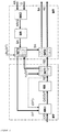
- FIG. 1 the reaction space RR of the autothermal reformer and the burner space BR of the burner can be seen. In both rooms, exothermic processes take place.
- the heat generated here is at least partially released from the reformate RE by means of the first heat exchanger WT1 on the one hand and from the burner exhaust gas BA by means of the second heat exchanger WT2 on the other hand.
- Both heat exchangers use this heat to heat a water / oxidant mixture H 2 O / T, which is then fed as water vapor / carrier gas mixture D / T of the first mixing chamber.
- FIG. 2 shows a cross section through a thermally coupled reformer and burner part of a reformer / burner system.
- the mixing chamber On the left side is the mixing chamber, in which on the one hand the fuel / oxidant mixture and on the other hand, the water vapor / carrier gas mixture is supplied by a further feed.
- the mixture is fed to the reaction space with the catalytically active surface in which it is converted to a hydrogen-rich mixture.
- the hot reformate flows to the right, with the heat being delivered to the first heat exchanger, which is arranged spirally in the reformer part. Thereafter, the reformate is passed into the burner part, flows through the third heat exchanger and then exits the system.
- the anode residual gas with the necessary amount of oxidizing agent enters the second mixing chamber for combustion of the anode residual gas.
- the gas mixture is fed to the burner chamber.
- a catalyst leads to the conversion of the anode residual gas by means of a total oxidation.
- the thus purified hot gas is cooled and discharged via the second and third heat exchangers.
- the supplied water / carrier gas mixture is first passed through the first and second heat exchangers, where it absorbs the heat released from the reformate and the burner exhaust gas and can be passed as water vapor / carrier gas mixture in the mixing chamber 1.
Landscapes
- Chemical & Material Sciences (AREA)
- Chemical Kinetics & Catalysis (AREA)
- Organic Chemistry (AREA)
- Health & Medical Sciences (AREA)
- General Health & Medical Sciences (AREA)
- Engineering & Computer Science (AREA)
- Combustion & Propulsion (AREA)
- Inorganic Chemistry (AREA)
- Hydrogen, Water And Hydrids (AREA)
- Fuel Cell (AREA)
Description
- Die Erfindung betrifft einen autothermen Reformer zur Erzeugung eines wasserstoffreichen Gasgemisches zur Nutzung in einer Brennstoffzelle.
- Zum Betrieb von Polymer-Elektrolytmembran (PEM)-Brennstoffzellen wird regelmäßig reiner Wasserstoff benötigt. Die Produktion von wasserstoffreichem Produktgas aus Kohlenwasserstoffen erfolgt üblicherweise mit Reformern. Dort wird katalytisch oder auch nicht katalytisch aus einem Kraftstoff, in der Regel aus Alkoholen (z. B. Methanol oder Ethanol) oder Kohlenwasserstoffen (z. B. Methan, Erdgas, Propan, Diesel, Kerosin) mit Wasser, mit einem Oxidationsmittel oder mit Wasser und einem Oxidationsmittel das so genannte Reformat erzeugt. Dieses Reformat wird, nachdem es in einer mehrstufigen Gasreinigung, die in der Regel aus einem zweistufigen Shiftreaktor und einer anschließenden präferenziellen Oxidation besteht, gereinigt und anschließend der Polymer-Elektrolyt-Membran-Brennstoffzelle zugeführt. Das Anodenrestgas der Polymer-Elektrolyt-Membran-Brennstoffzelle wird in einem Brenner mit einem Oxidationsmittel umgesetzt.
- Die einzelnen chemischen Reaktionen laufen in der Regel bei unterschiedlichen Temperaturen ab, so beispielsweise die Reformierung bei 250 bis 900 °C und die sich anschließende Reinigung des Reformats bei 200 - 400 °C im Shiftreaktor und bei 50 - 200 °C im Reaktor zur präferentiellen Oxidation. Zudem wird bei den einzelnen Reaktionen teilweise Wärme produziert oder auch zusätzliche Wärme benötigt. Die Dokumente
US2004/187386 ,DE10057537 undUS2003/046867 beschreiben alle Vorrichtungen zur Erzeugung von wasserstoffreichem Produktgas mit einem Brenner und einem Reformer. - Aufgabe der Erfindung ist es, einen autothermen Reformer zur Erzeugung von Wasserstoff für eine Brennstoffzelle zur Verfügung zu stellen, der möglichst autark von äußerer Wärmezufuhr betrieben werden kann. Insbesondere soll der autotherme Reformer den für den Reformierungsprozess erforderlichen Dampf bereitstellen und die Wärme des Abgases des Brenners nutzen.
- Die grundlegende Idee der Erfindung ist es, die Reformierung und die Nachverbrennung des Anodenabgases thermisch zu koppeln, so dass eine solche Einheit im stationären Betrieb nahezu autark betrieben werden kann.
- Das erfindungsgemäße Reformer/Brenner-System löst vorteilhaft das Problem der Verdampfung der Wassers, welches für die autotherme Reformierung benötigt wird, indem die Wärme des Brennerabgases und des Reformats genutzt wird. Überdies wird durch den Wärmeaustrag aus dem Reformat die Reformattemperatur gleichzeitig auf das Temperaturniveau der anschließenden Reinigungsstufe, der Entschwefelung oder der Hochtemperaturshiftstufe abgesenkt.
- Die erfindungsgemäße Vorrichtung weist dazu einen Reformerteil und einen Brennerteil auf. Im Reformerteil ist eine erste Mischkammer angeordnet, die einen ersten Einlass, der über eine Düse Kraftstoff und Oxidationsmittel einzuspeisen vermag sowie einen zweiten Einlass aufweist, der über eine Zuführung eine Wasserdampf/Trägergasmischung einzuspeisen vermag. Im Betrieb des autothermen Reformers vermischt sich das Oxidationsmittel mit dem Kraftstoff, dem Wasserdampf und dem Trägergas und die flüssigen Kraftstoffe (z. B. Diesel, Kerosin) werden verdampft. Dieses Gemisch wird anschließend in einem Reaktionsraum über eine katalytisch aktive Oberfläche geführt, wodurch es zu einer Umsetzung in ein wasserstoffreiches Gemisch (Reformat) kommt. Die dabei frei werdende Wärme wird von einem ersten Wärmeaustauscher und weiter von einem zweiten Wärmeaustauscher aufgenommen. Dadurch kühlt das Reformat ab, so dass es aus der erfindungsgemäßen Vorrichtung herausgeleitet werden kann. Das Reformat besitzt dann vorteilhaft eine Temperatur, die für gegebenenfalls nachgeschaltete Gasreinigungsschritte erforderlich ist.
- Gleichzeitig wird der erfindungsgemäßen Vorrichtung im Brennerteil Anodenrestgas einer Brennstoffzelle, insbesondere einer PEM, zugeführt. Dieses wird zusammen mit der erforderlichen Menge an einem Oxidationsmittel ebenfalls einer katalytischen Oberfläche zugeführt, wo es sich exotherm umsetzt. Die dabei frei werdende Wärme wird von einem dritten Wärmeaustauscher aufgenommen. Das abgekühlte Abgas wird dann aus der Vorrichtung abgeleitet. Es ist infolge der katalytischen Umsetzung regelmäßig schadstoffarm.
- Das für die chemische Umwandlung im Reformerteil benötigte Wasser/Trägergasgemisch wird über eine Zuleitung in die Vorrichtung eingebracht und über einen ersten und einen zweiten Wärmeaustauscher geleitet. Dabei wird es derart erhitzt, dass das Wasser vollständig verdampft und die Mischung überhitzt. Die Wasserdampf/Trägergasmischung wird anschließend im Reformerteil über eine Zuleitung dem verdampften Kraftstoff/Oxidationsmittelgemisch zugeführt.
- Das erfindungemäße Verfahren koppelt die chemische Umsetzung des Reformers mit der des Nachbrenners thermisch in einer Art und Weise, dass im optimalen Fall der gesamte für die Reformierung benötigte Wasserdampf ohne weitere externe Wärmezuführung erzeugt werden kann. Ferner setzt das Verfahren die Reformattemperatur auf die für die nachfolgende Gasreinigung erforderliche Temperatur herab, und kühlt zudem vorteilhaft das im Brenner zu Abgas umgesetzte Anodenrestgas der Brennstoffzelle.
- Das Verfahren lässt sich in geeigneter Weise durch die erfindungemäße Vorrichtung umsetzen. Diese weist einen Reformerteil mit einem Einlass für eine Kraftstoff/Oxidationsmittelmischung, einen Einlass für eine Wasser/Trägergasmischung, eine katalytische Oberfläche sowie einen ersten Wärmeaustauscher mit einer ersten Durchführung für das Reformat und einer zweiten Durchführung für eine Wasser/Trägergasmischung auf.
- Die Vorrichtung weist ferner einen Brennerteil mit einem Einlass für das Anodenrestgas aus einer Brennstoffzelle, einen Einlass für ein Oxidationsmittel, eine katalytische Oberfläche sowie einen dritten Wärmeaustauscher, eine erste Durchführung für das umgesetzte Anodenrestgas und eine zweite Durchführung für eine Wasser/Trägergasmischung auf.
- Der Brennerteil und der Reformerteil sind konstruktiv über wenigstens eine Zuführungsleitung einer Wasserdampf/Trägergasmischung miteinander gekoppelt.
- Nachfolgend wird der Gegenstand der Erfindung anhand von zwei Figuren näher erläutert, ohne dass der Gegenstand der Erfindung dadurch beschränkt wird.
- Es zeigen:
- Figur 1:
- die schematische Kopplung der Wärmeströme zwischen Reformerteil RT und Brennerteil BT.
- Figur 2:
- Schnittzeichnung eines Ausführungsbeispiels
- In den Figuren bedeuten:
- RT
- Reformerteil
- BT
- Brennerteil
- RR
- Reaktionsraum
- BR
- Brennerraum
- MK1
- erste Mischkammer
- MK2
- zweite Mischkammer
- WT1
- erster Wärmetauscher
- WT2
- zweiter Wärmetauscher
- WT3
- dritter Wärmetauscher
- C/O
- Kraftstoff/Oxidationsmittelgemisch
- H2O/T
- Wasser/Trägergasgemisch
- D/T
- Wasserdampf/Trägergasgemisch
- RE
- Reformat
- AR
- Anodenrestgas
- BA
- Brennerabgas
- AR/O
- Anodenrestgas/Oxidationsmittelgemisch
- BZ
- Brennerzufuhr
- RA
- Reformataustritt
- WLZ/DA
- Wasser- und Luftzufuhr/Dampfaustritt
- DZ
- Dampfzufuhr
- KLZ
- Kraftstoff- und Luftzufuhr
- In
Figur 1 sind der Reaktionsraum RR des autothermen Reformers und der Brennerraum BR des Brenners zu erkennen. In beiden Räumen laufen exotherme Prozesse ab. Die hier erzeugte Wärme wird einerseits aus dem Reformat RE mittels des ersten Wärmetauschers WT1 und anderseits aus dem Brennerabgas BA mittels des zweiten Wärmetauschers WT2 zumindest teilweise abgegeben. Beide Wärmetauscher nutzen diese Wärme zur Aufheizung eines Wasser/Oxidationsmittelgemisches H2O/T, welches anschließend als Wasserdampf/Trägergasgemisch D/T der ersten Mischkammer zugeführt wird. - Die
Figur 2 zeigt einen Querschnitt durch einen wärmetechnisch gekoppelten Reformer- und Brennerteil eines Reformer/Brenner-Systems. Auf der linken Seite befindet sich die Mischkammer, in die einerseits das Kraftstoff/Oxidationsmittelgemisch und andererseits durch eine weitere Zuführung das Wasserdampf/Trägergasgemisch zugeführt wird. Das Gemisch wird dem Reaktionsraum mit der katalytisch aktiven Oberfläche zugeführt, in dem es zu einem wasserstoffreichen Gemisch umgesetzt wird. Das heiße Reformat strömt nach rechts, wobei die Wärme an den ersten Wärmtauscher abgegeben wird, der spiralförmig im Reformerteil angeordnet ist. Danach wird das Reformat in den Brennerteil geleitet, durchströmt den dritten Wärmetauscher und tritt dann aus dem System aus. - Auf der rechten Seite treten das Anodenrestgas mit der notwendigen Menge an Oxidationsmittel zur Verbrennung des Anodenrestgases in die zweite Mischkammer ein. Das Gasgemisch wird dem Brennerraum zugeleitet. Auch hier führt ein Katalysator zur Umsetzung des Anodenrestgases mittels einer Totaloxidation. Das so gereinigte heiße Gas wird über den zweiten und dritten Wärmetauscher abgekühlt und abgeleitet.
- Das zugeführte Wasser/Trägergasgemisch wird zunächst über den ersten und zweiten Wärmetauscher geleitet, wo es die vom Reformat und dem Brennerabgas abgegebene Wärme aufnimmt und als Wasserdampf/Trägergasgemisch in die Mischkammer 1 geleitet werden kann.
Claims (6)
- Vorrichtung zur Erzeugung von wasserstoffreichem Produktgas, mit einem autothermen Reformer
mit einem Reformerteil,- welches eine Mischkammer mit einem Einlass für eine Kraftstoff/Oxidationsmittelmischung und einen Einlass für eine Wasserdampf/Trägergasmischung aufweist,- welches einen Reaktionsraum mit einer katalytisch aktiven Oberfläche aufweist,- welches einen Auslass für ein wasserstoffreiches Produktgas aufweist, und- welches einen Wärmeaustauscher (WT1) mit einer Durchführung für ein Reformat aufweist,und mit einem Brennerteil,- welches einen Einlass für ein Anodenrestgas aus einer Brennstoffzelle und einen Einlass für ein Oxidationsmittel aufweist,- welches einen Brennerraum mit einer katalytischen Oberfläche aufweist,- welches einen Auslass für das umgesetzte Restgas aufweist, und- welches einen Wärmeaustauscher (WT2) mit einer Durchführung für das umgesetzte Abgas sowie einen weiteren Wärmetauscher (WT3) aufweist,wobei der Reformerteil und der Brennerteil konstruktiv über wenigstens eine Zuführungsleitung für eine Wasserdampf/Trägergasmischung miteinander gekoppelt sind, dadurch gekennzeichnet, dass- der Wärmetauscher WT1 sowohl den Auslass des der Reformerteils als auch den Reaktionsraum selbst umgibt,- der Wärmetauscher WT2 sowohl den Auslass des Brennerteils als auch den Brennerraum selbst umgibt,- sowohl der Wärmetauscher WT1 als auch der Wärmetauscher WT2 eine Durchführung für eine Wasser/Trägergasmischung aufweisen, und- der Reformerteil und der Brennerteil konstruktiv über eine Durchführungsleitung für das wasserstoffreiche Produktgas miteinander gekoppelt sind. - Vorrichtung nach Anspruch 1, bei dem eine Leitung des Wasserdampf/Trägergasgemisches den Wärmetauscher WT1 mit dem Wärmetauscher WT2 verbindet.
- Vorrichtung nach einem der Ansprüche 1 bis 2, mit Spiralwärmetauschern als Wärmetauscher WT1 und WT2.
- Verfahren zum Betreiben einer Vorrichtung nach einem der Ansprüche 1 bis 3,
zur Erzeugung eines wasserstoffreichen Produktgases mit den Schritten:- im Reformerteil wird einer Mischkammer eine Wasserdampf/Trägergasmischung über eine Zuleitung und eine Kraftstoff/Oxidationsmittelmischung über eine Düse zugeführt,- die Kraftstoff/Wasserdampf/Oxidationsmittel/Trägergasmischung wird in einem Reaktionsraum des Reformerteils katalytisch in exothermen und endothermen Reaktionen in ein wasserstoffreiches Produktgas umgewandelt,- die dabei frei werdende Wärme wird von einem ersten Wärmetauscher WT1 und von einem weiteren Wärmetauscher WT3 aufgenommen,- im Brennerteil wird ein Anodenrestgas aus einer Brennstoffzelle in einem Brennerraum katalytisch in einer exothermen Reaktion in schadstoffarmes Abgas umgewandelt,- die dabei frei werdende Wärme wird von einem weiteren Wärmetauscher WT2 aufgenommen,- wobei das zugeführte Wasserdampf/Trägergasgemisch über die zwei Wärmetauscher WT1 und WT2 geleitet wird, wo es die vom Reformat und dem Brennerabgas abgegebene Wärme aufnimmt, und als Wasserdampf/Trägergasgemisch in die Mischkammer des Reformerteils geleitet wird. - Verfahren nach vorhergehendem Anspruch 4, bei dem die Wasserdampf/Trägergasmischung zunächst über den Wärmetauscher WT1 und anschließend über den Wärmetauscher WT2 geleitet wird.
- Verfahren nach vorhergehendem Anspruch 4, bei dem die Wasserdampf/Trägergasmischung zunächst über den Wärmetauscher WT2 und anschließend über den Wärmetauscher WT1 geleitet wird.
Applications Claiming Priority (2)
| Application Number | Priority Date | Filing Date | Title |
|---|---|---|---|
| DE102005026780A DE102005026780A1 (de) | 2005-06-10 | 2005-06-10 | Autothermer Reformer |
| PCT/DE2006/000946 WO2006131094A1 (de) | 2005-06-10 | 2006-05-31 | Autothermer reformer |
Publications (2)
| Publication Number | Publication Date |
|---|---|
| EP1888456A1 EP1888456A1 (de) | 2008-02-20 |
| EP1888456B1 true EP1888456B1 (de) | 2018-01-31 |
Family
ID=37054468
Family Applications (1)
| Application Number | Title | Priority Date | Filing Date |
|---|---|---|---|
| EP06753228.3A Active EP1888456B1 (de) | 2005-06-10 | 2006-05-31 | Autothermer reformer |
Country Status (5)
| Country | Link |
|---|---|
| US (1) | US20090136798A1 (de) |
| EP (1) | EP1888456B1 (de) |
| JP (1) | JP2008543020A (de) |
| DE (1) | DE102005026780A1 (de) |
| WO (1) | WO2006131094A1 (de) |
Families Citing this family (1)
| Publication number | Priority date | Publication date | Assignee | Title |
|---|---|---|---|---|
| GB0921660D0 (en) * | 2009-12-10 | 2010-01-27 | Zettner Michael | Method for increasing the efficiency of a heat exchanger |
Family Cites Families (17)
| Publication number | Priority date | Publication date | Assignee | Title |
|---|---|---|---|---|
| JP2625551B2 (ja) * | 1989-08-17 | 1997-07-02 | 三菱重工業株式会社 | メタノールリフォーマ |
| JP2003521363A (ja) * | 1998-11-13 | 2003-07-15 | エンゲルハード・コーポレーシヨン | 排気ガス放出を減少させる触媒および方法 |
| DE19908905C2 (de) * | 1999-03-02 | 2003-03-20 | Daimler Chrysler Ag | Brennstoffzellensystem mit zugeordneter Wasserstofferzeugungsanlage |
| DE10010071C2 (de) * | 2000-03-02 | 2002-04-25 | Xcellsis Gmbh | Gaserzeugungsvorrichtung und Verfahren zum Starten derselben |
| DE10010070A1 (de) * | 2000-03-02 | 2001-09-20 | Xcellsis Gmbh | Gaserzeugungsvorrichtung |
| DE10141843A1 (de) * | 2000-08-30 | 2002-06-13 | Denso Corp | Wasserstoffversorgungsvorrichtung |
| DE10057537A1 (de) * | 2000-11-20 | 2002-06-06 | Viessmann Werke Kg | Apparat zur Erzeugung von Wasserstoff |
| WO2002085509A1 (en) * | 2001-04-24 | 2002-10-31 | Hydrogen Burner Technology, Inc. | Flat plate integrated reactor |
| EP1392597A1 (de) * | 2001-05-02 | 2004-03-03 | Hydrogen Burner Technology, Inc. | Wasserstofferzeugung |
| DE10142578A1 (de) * | 2001-09-02 | 2003-04-10 | Webasto Thermosysteme Gmbh | System zum Erzeugen elektrischer Energie und Verfahren zum Betreiben eines Systems zum Erzeugen elektrischer Energie |
| US6799393B2 (en) * | 2001-09-12 | 2004-10-05 | Westinghouse Air Brake Technologies Corporation | Double trolley overhead door operator |
| JP4923371B2 (ja) * | 2001-09-21 | 2012-04-25 | トヨタ自動車株式会社 | 水素分離膜を備える水素生成装置の起動方法 |
| US6838062B2 (en) * | 2001-11-19 | 2005-01-04 | General Motors Corporation | Integrated fuel processor for rapid start and operational control |
| US20030223926A1 (en) * | 2002-04-14 | 2003-12-04 | Edlund David J. | Steam reforming fuel processor, burner assembly, and methods of operating the same |
| US6712603B2 (en) * | 2002-08-07 | 2004-03-30 | General Motors Corporation | Multiple port catalytic combustion device and method of operating same |
| JP2004220836A (ja) * | 2003-01-10 | 2004-08-05 | Babcock Hitachi Kk | 燃料電池発電システム |
| US6932958B2 (en) * | 2003-03-26 | 2005-08-23 | Gas Technology Institute | Simplified three-stage fuel processor |
-
2005
- 2005-06-10 DE DE102005026780A patent/DE102005026780A1/de not_active Withdrawn
-
2006
- 2006-05-31 US US11/921,495 patent/US20090136798A1/en not_active Abandoned
- 2006-05-31 WO PCT/DE2006/000946 patent/WO2006131094A1/de not_active Ceased
- 2006-05-31 EP EP06753228.3A patent/EP1888456B1/de active Active
- 2006-05-31 JP JP2008515040A patent/JP2008543020A/ja active Pending
Also Published As
| Publication number | Publication date |
|---|---|
| JP2008543020A (ja) | 2008-11-27 |
| DE102005026780A1 (de) | 2006-12-21 |
| US20090136798A1 (en) | 2009-05-28 |
| WO2006131094A1 (de) | 2006-12-14 |
| EP1888456A1 (de) | 2008-02-20 |
Similar Documents
| Publication | Publication Date | Title |
|---|---|---|
| EP0921585B1 (de) | Vorrichtung und Verfahren zur Wasserdampfreformierung eines Kohlenwasserstoffs | |
| US6818198B2 (en) | Hydrogen enrichment scheme for autothermal reforming | |
| DE19746251C2 (de) | Anlage zur Wasserdampfreformierung eines Kohlenwasserstoffs und Betriebsverfahren hierfür | |
| EP0887307B1 (de) | Vorrichtung und Verfahren zum Starten der Vorrichtung zur Erzeugung von wasserstoffreichem Gas | |
| DE10142999B4 (de) | Hocheffiziente, kompakte Reformereinheit zur Wasserstofferzeugung aus gasförmigen Kohlenwasserstoffen im kleinen Leistungsbereich | |
| EP1694598A2 (de) | Reformer und verfahren zum unsetzen von brennstoff und oxidationsmittel zu reformat | |
| WO2023144335A1 (de) | Verfahren und anlage zur herstellung von wasserstoff aus ammoniak | |
| WO2010020358A2 (de) | Mehrstufige reaktorkaskade zur russfreien herstellung von synthesegas | |
| EP2455334A1 (de) | System für die Verarbeitung von Ethanol | |
| DE102017001564B4 (de) | Verfahren zum Starten einer Brennstoffzellenanordnung und Brennstoffzellenanordnung | |
| EP1817813A1 (de) | Brennstoffzellenheizgerät sowie verfahren zum betreiben eines brennstoffzellenheizgeräts | |
| WO2003021696A2 (de) | System zum erzeugen elektrischer energie und verfahren zum betreiben eines systems zum erzeugen elektrischer energie | |
| DE19902926A1 (de) | Wasserdampfreformierungsanlage und Betriebsverfahren hierfür | |
| EP1571123A1 (de) | Reformer und Verfahren zum Umsetzen von Brennstoff und Oxidationsmittel zu Reformat | |
| DE10104607A1 (de) | Gaserzeugungssystem für ein Brennstoffzellensystem und Verfahren zum Betrieb eines Gaserzeugungssystems | |
| DE102007018311B4 (de) | Zweistufiger Reformer und Verfahren zum Betreiben eines Reformers | |
| WO2006131094A1 (de) | Autothermer reformer | |
| WO2003014012A1 (en) | System and method for preparing fuel for fuel processing system | |
| EP1717198A2 (de) | Verfahren und Vorrichtung zur Hochtemperaturreformierung | |
| DE102008037028B4 (de) | Brennstoffzellensystem für gasförmige Kohlenwassserstoffe und dazugehöriges Betriebsverfahren | |
| DE10041712A1 (de) | Autotherme Brenngaserzeugungseinheit für Brennstoffzellen | |
| EP1207134B1 (de) | Gaserzeugungssystem für einen Reformer | |
| WO2008151593A1 (de) | Zweistufiger gasreformer | |
| DE10149658B4 (de) | Vorrichtung und Verfahren zur katalytischen Brenngasaufbereitung eines wasserstoffreichen Reformergases für eine Brennstoffzelle | |
| DE102008020407A1 (de) | Apparatur zur effizienten Erzeugung von Wasserstoff aus kohlenwasserstoffhaltigen Gasen mittels Dampfreformierung |
Legal Events
| Date | Code | Title | Description |
|---|---|---|---|
| PUAI | Public reference made under article 153(3) epc to a published international application that has entered the european phase |
Free format text: ORIGINAL CODE: 0009012 |
|
| 17P | Request for examination filed |
Effective date: 20071129 |
|
| AK | Designated contracting states |
Kind code of ref document: A1 Designated state(s): AT BE BG CH CY CZ DE DK EE ES FI FR GB GR HU IE IS IT LI LT LU LV MC NL PL PT RO SE SI SK TR |
|
| RIN1 | Information on inventor provided before grant (corrected) |
Inventor name: STOLTEN, DETLEF Inventor name: PASEL, JOACHIM Inventor name: PETERS, RALF Inventor name: TSCHAUDER, ANDREAS |
|
| DAX | Request for extension of the european patent (deleted) | ||
| 17Q | First examination report despatched |
Effective date: 20161125 |
|
| GRAP | Despatch of communication of intention to grant a patent |
Free format text: ORIGINAL CODE: EPIDOSNIGR1 |
|
| INTG | Intention to grant announced |
Effective date: 20171011 |
|
| GRAS | Grant fee paid |
Free format text: ORIGINAL CODE: EPIDOSNIGR3 |
|
| RIN1 | Information on inventor provided before grant (corrected) |
Inventor name: STOLTEN, DETLEF Inventor name: PASEL, JOACHIM Inventor name: TSCHAUDER, ANDREAS Inventor name: PETERS, RALF |
|
| GRAA | (expected) grant |
Free format text: ORIGINAL CODE: 0009210 |
|
| AK | Designated contracting states |
Kind code of ref document: B1 Designated state(s): AT BE BG CH CY CZ DE DK EE ES FI FR GB GR HU IE IS IT LI LT LU LV MC NL PL PT RO SE SI SK TR |
|
| REG | Reference to a national code |
Ref country code: GB Ref legal event code: FG4D Free format text: NOT ENGLISH Ref country code: CH Ref legal event code: EP |
|
| REG | Reference to a national code |
Ref country code: AT Ref legal event code: REF Ref document number: 967188 Country of ref document: AT Kind code of ref document: T Effective date: 20180215 |
|
| REG | Reference to a national code |
Ref country code: IE Ref legal event code: FG4D Free format text: LANGUAGE OF EP DOCUMENT: GERMAN |
|
| REG | Reference to a national code |
Ref country code: DE Ref legal event code: R096 Ref document number: 502006015801 Country of ref document: DE |
|
| REG | Reference to a national code |
Ref country code: FR Ref legal event code: PLFP Year of fee payment: 13 |
|
| REG | Reference to a national code |
Ref country code: NL Ref legal event code: MP Effective date: 20180131 |
|
| REG | Reference to a national code |
Ref country code: LT Ref legal event code: MG4D |
|
| PG25 | Lapsed in a contracting state [announced via postgrant information from national office to epo] |
Ref country code: FI Free format text: LAPSE BECAUSE OF FAILURE TO SUBMIT A TRANSLATION OF THE DESCRIPTION OR TO PAY THE FEE WITHIN THE PRESCRIBED TIME-LIMIT Effective date: 20180131 Ref country code: LT Free format text: LAPSE BECAUSE OF FAILURE TO SUBMIT A TRANSLATION OF THE DESCRIPTION OR TO PAY THE FEE WITHIN THE PRESCRIBED TIME-LIMIT Effective date: 20180131 Ref country code: ES Free format text: LAPSE BECAUSE OF FAILURE TO SUBMIT A TRANSLATION OF THE DESCRIPTION OR TO PAY THE FEE WITHIN THE PRESCRIBED TIME-LIMIT Effective date: 20180131 Ref country code: NL Free format text: LAPSE BECAUSE OF FAILURE TO SUBMIT A TRANSLATION OF THE DESCRIPTION OR TO PAY THE FEE WITHIN THE PRESCRIBED TIME-LIMIT Effective date: 20180131 |
|
| PG25 | Lapsed in a contracting state [announced via postgrant information from national office to epo] |
Ref country code: PL Free format text: LAPSE BECAUSE OF FAILURE TO SUBMIT A TRANSLATION OF THE DESCRIPTION OR TO PAY THE FEE WITHIN THE PRESCRIBED TIME-LIMIT Effective date: 20180131 Ref country code: LV Free format text: LAPSE BECAUSE OF FAILURE TO SUBMIT A TRANSLATION OF THE DESCRIPTION OR TO PAY THE FEE WITHIN THE PRESCRIBED TIME-LIMIT Effective date: 20180131 Ref country code: IS Free format text: LAPSE BECAUSE OF FAILURE TO SUBMIT A TRANSLATION OF THE DESCRIPTION OR TO PAY THE FEE WITHIN THE PRESCRIBED TIME-LIMIT Effective date: 20180531 Ref country code: SE Free format text: LAPSE BECAUSE OF FAILURE TO SUBMIT A TRANSLATION OF THE DESCRIPTION OR TO PAY THE FEE WITHIN THE PRESCRIBED TIME-LIMIT Effective date: 20180131 Ref country code: BG Free format text: LAPSE BECAUSE OF FAILURE TO SUBMIT A TRANSLATION OF THE DESCRIPTION OR TO PAY THE FEE WITHIN THE PRESCRIBED TIME-LIMIT Effective date: 20180430 Ref country code: GR Free format text: LAPSE BECAUSE OF FAILURE TO SUBMIT A TRANSLATION OF THE DESCRIPTION OR TO PAY THE FEE WITHIN THE PRESCRIBED TIME-LIMIT Effective date: 20180501 |
|
| PG25 | Lapsed in a contracting state [announced via postgrant information from national office to epo] |
Ref country code: EE Free format text: LAPSE BECAUSE OF FAILURE TO SUBMIT A TRANSLATION OF THE DESCRIPTION OR TO PAY THE FEE WITHIN THE PRESCRIBED TIME-LIMIT Effective date: 20180131 Ref country code: RO Free format text: LAPSE BECAUSE OF FAILURE TO SUBMIT A TRANSLATION OF THE DESCRIPTION OR TO PAY THE FEE WITHIN THE PRESCRIBED TIME-LIMIT Effective date: 20180131 Ref country code: IT Free format text: LAPSE BECAUSE OF FAILURE TO SUBMIT A TRANSLATION OF THE DESCRIPTION OR TO PAY THE FEE WITHIN THE PRESCRIBED TIME-LIMIT Effective date: 20180131 |
|
| REG | Reference to a national code |
Ref country code: DE Ref legal event code: R097 Ref document number: 502006015801 Country of ref document: DE |
|
| PG25 | Lapsed in a contracting state [announced via postgrant information from national office to epo] |
Ref country code: SK Free format text: LAPSE BECAUSE OF FAILURE TO SUBMIT A TRANSLATION OF THE DESCRIPTION OR TO PAY THE FEE WITHIN THE PRESCRIBED TIME-LIMIT Effective date: 20180131 Ref country code: CZ Free format text: LAPSE BECAUSE OF FAILURE TO SUBMIT A TRANSLATION OF THE DESCRIPTION OR TO PAY THE FEE WITHIN THE PRESCRIBED TIME-LIMIT Effective date: 20180131 Ref country code: DK Free format text: LAPSE BECAUSE OF FAILURE TO SUBMIT A TRANSLATION OF THE DESCRIPTION OR TO PAY THE FEE WITHIN THE PRESCRIBED TIME-LIMIT Effective date: 20180131 |
|
| PLBE | No opposition filed within time limit |
Free format text: ORIGINAL CODE: 0009261 |
|
| STAA | Information on the status of an ep patent application or granted ep patent |
Free format text: STATUS: NO OPPOSITION FILED WITHIN TIME LIMIT |
|
| 26N | No opposition filed |
Effective date: 20181102 |
|
| PG25 | Lapsed in a contracting state [announced via postgrant information from national office to epo] |
Ref country code: MC Free format text: LAPSE BECAUSE OF FAILURE TO SUBMIT A TRANSLATION OF THE DESCRIPTION OR TO PAY THE FEE WITHIN THE PRESCRIBED TIME-LIMIT Effective date: 20180131 |
|
| PG25 | Lapsed in a contracting state [announced via postgrant information from national office to epo] |
Ref country code: SI Free format text: LAPSE BECAUSE OF FAILURE TO SUBMIT A TRANSLATION OF THE DESCRIPTION OR TO PAY THE FEE WITHIN THE PRESCRIBED TIME-LIMIT Effective date: 20180131 |
|
| REG | Reference to a national code |
Ref country code: IE Ref legal event code: MM4A |
|
| PG25 | Lapsed in a contracting state [announced via postgrant information from national office to epo] |
Ref country code: LU Free format text: LAPSE BECAUSE OF NON-PAYMENT OF DUE FEES Effective date: 20180531 |
|
| PG25 | Lapsed in a contracting state [announced via postgrant information from national office to epo] |
Ref country code: IE Free format text: LAPSE BECAUSE OF NON-PAYMENT OF DUE FEES Effective date: 20180531 |
|
| PG25 | Lapsed in a contracting state [announced via postgrant information from national office to epo] |
Ref country code: TR Free format text: LAPSE BECAUSE OF FAILURE TO SUBMIT A TRANSLATION OF THE DESCRIPTION OR TO PAY THE FEE WITHIN THE PRESCRIBED TIME-LIMIT Effective date: 20180131 |
|
| PG25 | Lapsed in a contracting state [announced via postgrant information from national office to epo] |
Ref country code: PT Free format text: LAPSE BECAUSE OF FAILURE TO SUBMIT A TRANSLATION OF THE DESCRIPTION OR TO PAY THE FEE WITHIN THE PRESCRIBED TIME-LIMIT Effective date: 20180131 Ref country code: HU Free format text: LAPSE BECAUSE OF FAILURE TO SUBMIT A TRANSLATION OF THE DESCRIPTION OR TO PAY THE FEE WITHIN THE PRESCRIBED TIME-LIMIT; INVALID AB INITIO Effective date: 20060531 |
|
| PG25 | Lapsed in a contracting state [announced via postgrant information from national office to epo] |
Ref country code: CY Free format text: LAPSE BECAUSE OF FAILURE TO SUBMIT A TRANSLATION OF THE DESCRIPTION OR TO PAY THE FEE WITHIN THE PRESCRIBED TIME-LIMIT Effective date: 20180131 |
|
| P01 | Opt-out of the competence of the unified patent court (upc) registered |
Effective date: 20230517 |
|
| PGFP | Annual fee paid to national office [announced via postgrant information from national office to epo] |
Ref country code: FR Payment date: 20230517 Year of fee payment: 18 Ref country code: DE Payment date: 20230519 Year of fee payment: 18 Ref country code: CH Payment date: 20230605 Year of fee payment: 18 |
|
| PGFP | Annual fee paid to national office [announced via postgrant information from national office to epo] |
Ref country code: AT Payment date: 20230516 Year of fee payment: 18 |
|
| PGFP | Annual fee paid to national office [announced via postgrant information from national office to epo] |
Ref country code: BE Payment date: 20230517 Year of fee payment: 18 |
|
| PGFP | Annual fee paid to national office [announced via postgrant information from national office to epo] |
Ref country code: GB Payment date: 20230522 Year of fee payment: 18 |
|
| REG | Reference to a national code |
Ref country code: DE Ref legal event code: R119 Ref document number: 502006015801 Country of ref document: DE |
|
| REG | Reference to a national code |
Ref country code: CH Ref legal event code: PL |
|
| REG | Reference to a national code |
Ref country code: AT Ref legal event code: MM01 Ref document number: 967188 Country of ref document: AT Kind code of ref document: T Effective date: 20240531 |
|
| PG25 | Lapsed in a contracting state [announced via postgrant information from national office to epo] |
Ref country code: AT Free format text: LAPSE BECAUSE OF NON-PAYMENT OF DUE FEES Effective date: 20240531 |
|
| GBPC | Gb: european patent ceased through non-payment of renewal fee |
Effective date: 20240531 |
|
| PG25 | Lapsed in a contracting state [announced via postgrant information from national office to epo] |
Ref country code: AT Free format text: LAPSE BECAUSE OF NON-PAYMENT OF DUE FEES Effective date: 20240531 Ref country code: CH Free format text: LAPSE BECAUSE OF NON-PAYMENT OF DUE FEES Effective date: 20240531 |
|
| REG | Reference to a national code |
Ref country code: BE Ref legal event code: MM Effective date: 20240531 |
|
| PG25 | Lapsed in a contracting state [announced via postgrant information from national office to epo] |
Ref country code: DE Free format text: LAPSE BECAUSE OF NON-PAYMENT OF DUE FEES Effective date: 20241203 |
|
| PG25 | Lapsed in a contracting state [announced via postgrant information from national office to epo] |
Ref country code: BE Free format text: LAPSE BECAUSE OF NON-PAYMENT OF DUE FEES Effective date: 20240531 |
|
| PG25 | Lapsed in a contracting state [announced via postgrant information from national office to epo] |
Ref country code: FR Free format text: LAPSE BECAUSE OF NON-PAYMENT OF DUE FEES Effective date: 20240531 |
|
| PG25 | Lapsed in a contracting state [announced via postgrant information from national office to epo] |
Ref country code: GB Free format text: LAPSE BECAUSE OF NON-PAYMENT OF DUE FEES Effective date: 20240531 |