EP1888338B2 - Printing machine and a method for producing a printed product - Google Patents
Printing machine and a method for producing a printed product Download PDFInfo
- Publication number
- EP1888338B2 EP1888338B2 EP06754883.4A EP06754883A EP1888338B2 EP 1888338 B2 EP1888338 B2 EP 1888338B2 EP 06754883 A EP06754883 A EP 06754883A EP 1888338 B2 EP1888338 B2 EP 1888338B2
- Authority
- EP
- European Patent Office
- Prior art keywords
- printing
- printing press
- press according
- printed
- checking
- Prior art date
- Legal status (The legal status is an assumption and is not a legal conclusion. Google has not performed a legal analysis and makes no representation as to the accuracy of the status listed.)
- Not-in-force
Links
- 238000007639 printing Methods 0.000 title claims abstract description 211
- 238000004519 manufacturing process Methods 0.000 title description 20
- 238000007689 inspection Methods 0.000 claims abstract description 78
- 239000000463 material Substances 0.000 claims abstract description 22
- 238000000034 method Methods 0.000 claims description 44
- 230000003287 optical effect Effects 0.000 claims description 29
- 239000003086 colorant Substances 0.000 claims description 10
- 239000004020 conductor Substances 0.000 claims description 9
- 238000007645 offset printing Methods 0.000 claims description 9
- 229920000642 polymer Polymers 0.000 claims description 6
- 239000004065 semiconductor Substances 0.000 claims description 3
- 239000012777 electrically insulating material Substances 0.000 claims description 2
- 238000007644 letterpress printing Methods 0.000 claims 1
- 238000011144 upstream manufacturing Methods 0.000 claims 1
- 238000012360 testing method Methods 0.000 abstract description 43
- 238000005286 illumination Methods 0.000 description 49
- 239000000976 ink Substances 0.000 description 27
- 239000000758 substrate Substances 0.000 description 19
- 238000001514 detection method Methods 0.000 description 18
- 230000006870 function Effects 0.000 description 16
- 238000012545 processing Methods 0.000 description 15
- 238000005259 measurement Methods 0.000 description 14
- 230000008569 process Effects 0.000 description 12
- 239000000123 paper Substances 0.000 description 9
- 230000008901 benefit Effects 0.000 description 8
- 238000004458 analytical method Methods 0.000 description 6
- 230000005540 biological transmission Effects 0.000 description 6
- 230000007547 defect Effects 0.000 description 5
- 239000003973 paint Substances 0.000 description 5
- 230000006399 behavior Effects 0.000 description 4
- 239000011248 coating agent Substances 0.000 description 3
- 238000000576 coating method Methods 0.000 description 3
- 238000012937 correction Methods 0.000 description 3
- 230000001419 dependent effect Effects 0.000 description 3
- 238000001035 drying Methods 0.000 description 3
- 238000011156 evaluation Methods 0.000 description 3
- 238000004806 packaging method and process Methods 0.000 description 3
- 230000035945 sensitivity Effects 0.000 description 3
- 238000000926 separation method Methods 0.000 description 3
- 239000007787 solid Substances 0.000 description 3
- 238000012546 transfer Methods 0.000 description 3
- 238000012935 Averaging Methods 0.000 description 2
- 239000000853 adhesive Substances 0.000 description 2
- 230000001070 adhesive effect Effects 0.000 description 2
- 229910052782 aluminium Inorganic materials 0.000 description 2
- XAGFODPZIPBFFR-UHFFFAOYSA-N aluminium Chemical compound [Al] XAGFODPZIPBFFR-UHFFFAOYSA-N 0.000 description 2
- 239000011111 cardboard Substances 0.000 description 2
- 230000008859 change Effects 0.000 description 2
- 230000004456 color vision Effects 0.000 description 2
- 238000004040 coloring Methods 0.000 description 2
- 230000001276 controlling effect Effects 0.000 description 2
- 238000004043 dyeing Methods 0.000 description 2
- 238000005516 engineering process Methods 0.000 description 2
- 230000010354 integration Effects 0.000 description 2
- 238000002372 labelling Methods 0.000 description 2
- -1 polyethylene Polymers 0.000 description 2
- 238000003908 quality control method Methods 0.000 description 2
- 230000001105 regulatory effect Effects 0.000 description 2
- 230000009466 transformation Effects 0.000 description 2
- 230000000007 visual effect Effects 0.000 description 2
- 239000002699 waste material Substances 0.000 description 2
- XLYOFNOQVPJJNP-UHFFFAOYSA-N water Substances O XLYOFNOQVPJJNP-UHFFFAOYSA-N 0.000 description 2
- RYGMFSIKBFXOCR-UHFFFAOYSA-N Copper Chemical compound [Cu] RYGMFSIKBFXOCR-UHFFFAOYSA-N 0.000 description 1
- 102100026064 Exosome complex component RRP43 Human genes 0.000 description 1
- 241000237858 Gastropoda Species 0.000 description 1
- 101001055989 Homo sapiens Exosome complex component RRP43 Proteins 0.000 description 1
- 239000004698 Polyethylene Substances 0.000 description 1
- 239000004743 Polypropylene Substances 0.000 description 1
- 239000004793 Polystyrene Substances 0.000 description 1
- BQCADISMDOOEFD-UHFFFAOYSA-N Silver Chemical compound [Ag] BQCADISMDOOEFD-UHFFFAOYSA-N 0.000 description 1
- 229910000831 Steel Inorganic materials 0.000 description 1
- 239000004904 UV filter Substances 0.000 description 1
- 230000009471 action Effects 0.000 description 1
- 230000003213 activating effect Effects 0.000 description 1
- 230000001154 acute effect Effects 0.000 description 1
- 230000003044 adaptive effect Effects 0.000 description 1
- 230000032683 aging Effects 0.000 description 1
- 238000003705 background correction Methods 0.000 description 1
- 239000003795 chemical substances by application Substances 0.000 description 1
- 238000004737 colorimetric analysis Methods 0.000 description 1
- 238000005094 computer simulation Methods 0.000 description 1
- 229920001940 conductive polymer Polymers 0.000 description 1
- 238000010276 construction Methods 0.000 description 1
- 238000011109 contamination Methods 0.000 description 1
- 229910052802 copper Inorganic materials 0.000 description 1
- 239000010949 copper Substances 0.000 description 1
- 125000004122 cyclic group Chemical group 0.000 description 1
- 238000009795 derivation Methods 0.000 description 1
- 238000009826 distribution Methods 0.000 description 1
- 230000000694 effects Effects 0.000 description 1
- 238000004146 energy storage Methods 0.000 description 1
- 229920005648 ethylene methacrylic acid copolymer Polymers 0.000 description 1
- 238000011990 functional testing Methods 0.000 description 1
- 238000007646 gravure printing Methods 0.000 description 1
- 238000010191 image analysis Methods 0.000 description 1
- 230000001939 inductive effect Effects 0.000 description 1
- 238000009434 installation Methods 0.000 description 1
- 229920000554 ionomer Polymers 0.000 description 1
- 239000007788 liquid Substances 0.000 description 1
- 238000011068 loading method Methods 0.000 description 1
- 238000012423 maintenance Methods 0.000 description 1
- 238000007726 management method Methods 0.000 description 1
- 229910052751 metal Inorganic materials 0.000 description 1
- 239000002184 metal Substances 0.000 description 1
- 238000002156 mixing Methods 0.000 description 1
- 239000011368 organic material Substances 0.000 description 1
- 230000010355 oscillation Effects 0.000 description 1
- 239000010893 paper waste Substances 0.000 description 1
- 239000011087 paperboard Substances 0.000 description 1
- 230000001766 physiological effect Effects 0.000 description 1
- 229920000728 polyester Polymers 0.000 description 1
- 229920000573 polyethylene Polymers 0.000 description 1
- 229920000098 polyolefin Polymers 0.000 description 1
- 229920001155 polypropylene Polymers 0.000 description 1
- 229920002223 polystyrene Polymers 0.000 description 1
- 239000002243 precursor Substances 0.000 description 1
- 238000003825 pressing Methods 0.000 description 1
- 238000004080 punching Methods 0.000 description 1
- 238000013139 quantization Methods 0.000 description 1
- 230000005855 radiation Effects 0.000 description 1
- 230000004044 response Effects 0.000 description 1
- 230000000717 retained effect Effects 0.000 description 1
- 239000000523 sample Substances 0.000 description 1
- 238000007650 screen-printing Methods 0.000 description 1
- 229910052709 silver Inorganic materials 0.000 description 1
- 239000004332 silver Substances 0.000 description 1
- 239000002904 solvent Substances 0.000 description 1
- 238000011895 specific detection Methods 0.000 description 1
- 239000007921 spray Substances 0.000 description 1
- 230000000087 stabilizing effect Effects 0.000 description 1
- 238000010972 statistical evaluation Methods 0.000 description 1
- 239000010959 steel Substances 0.000 description 1
- 238000003860 storage Methods 0.000 description 1
- 238000012549 training Methods 0.000 description 1
- 230000001960 triggered effect Effects 0.000 description 1
- 238000012795 verification Methods 0.000 description 1
- 238000011179 visual inspection Methods 0.000 description 1
- 230000037303 wrinkles Effects 0.000 description 1
Images


Classifications
-
- B—PERFORMING OPERATIONS; TRANSPORTING
- B41—PRINTING; LINING MACHINES; TYPEWRITERS; STAMPS
- B41F—PRINTING MACHINES OR PRESSES
- B41F33/00—Indicating, counting, warning, control or safety devices
- B41F33/0036—Devices for scanning or checking the printed matter for quality control
-
- B—PERFORMING OPERATIONS; TRANSPORTING
- B41—PRINTING; LINING MACHINES; TYPEWRITERS; STAMPS
- B41F—PRINTING MACHINES OR PRESSES
- B41F17/00—Printing apparatus or machines of special types or for particular purposes, not otherwise provided for
-
- H—ELECTRICITY
- H05—ELECTRIC TECHNIQUES NOT OTHERWISE PROVIDED FOR
- H05K—PRINTED CIRCUITS; CASINGS OR CONSTRUCTIONAL DETAILS OF ELECTRIC APPARATUS; MANUFACTURE OF ASSEMBLAGES OF ELECTRICAL COMPONENTS
- H05K3/00—Apparatus or processes for manufacturing printed circuits
- H05K3/10—Apparatus or processes for manufacturing printed circuits in which conductive material is applied to the insulating support in such a manner as to form the desired conductive pattern
- H05K3/12—Apparatus or processes for manufacturing printed circuits in which conductive material is applied to the insulating support in such a manner as to form the desired conductive pattern using thick film techniques, e.g. printing techniques to apply the conductive material or similar techniques for applying conductive paste or ink patterns
- H05K3/1275—Apparatus or processes for manufacturing printed circuits in which conductive material is applied to the insulating support in such a manner as to form the desired conductive pattern using thick film techniques, e.g. printing techniques to apply the conductive material or similar techniques for applying conductive paste or ink patterns by other printing techniques, e.g. letterpress printing, intaglio printing, lithographic printing, offset printing
-
- H—ELECTRICITY
- H05—ELECTRIC TECHNIQUES NOT OTHERWISE PROVIDED FOR
- H05K—PRINTED CIRCUITS; CASINGS OR CONSTRUCTIONAL DETAILS OF ELECTRIC APPARATUS; MANUFACTURE OF ASSEMBLAGES OF ELECTRICAL COMPONENTS
- H05K1/00—Printed circuits
- H05K1/02—Details
- H05K1/0266—Marks, test patterns or identification means
- H05K1/0269—Marks, test patterns or identification means for visual or optical inspection
-
- H—ELECTRICITY
- H05—ELECTRIC TECHNIQUES NOT OTHERWISE PROVIDED FOR
- H05K—PRINTED CIRCUITS; CASINGS OR CONSTRUCTIONAL DETAILS OF ELECTRIC APPARATUS; MANUFACTURE OF ASSEMBLAGES OF ELECTRICAL COMPONENTS
- H05K2201/00—Indexing scheme relating to printed circuits covered by H05K1/00
- H05K2201/09—Shape and layout
- H05K2201/09818—Shape or layout details not covered by a single group of H05K2201/09009 - H05K2201/09809
- H05K2201/09936—Marks, inscriptions, etc. for information
-
- H—ELECTRICITY
- H05—ELECTRIC TECHNIQUES NOT OTHERWISE PROVIDED FOR
- H05K—PRINTED CIRCUITS; CASINGS OR CONSTRUCTIONAL DETAILS OF ELECTRIC APPARATUS; MANUFACTURE OF ASSEMBLAGES OF ELECTRICAL COMPONENTS
- H05K2203/00—Indexing scheme relating to apparatus or processes for manufacturing printed circuits covered by H05K3/00
- H05K2203/15—Position of the PCB during processing
- H05K2203/1545—Continuous processing, i.e. involving rolls moving a band-like or solid carrier along a continuous production path
-
- H—ELECTRICITY
- H05—ELECTRIC TECHNIQUES NOT OTHERWISE PROVIDED FOR
- H05K—PRINTED CIRCUITS; CASINGS OR CONSTRUCTIONAL DETAILS OF ELECTRIC APPARATUS; MANUFACTURE OF ASSEMBLAGES OF ELECTRICAL COMPONENTS
- H05K2203/00—Indexing scheme relating to apparatus or processes for manufacturing printed circuits covered by H05K3/00
- H05K2203/16—Inspection; Monitoring; Aligning
- H05K2203/163—Monitoring a manufacturing process
Definitions
- the invention relates to a printing press and to a method for producing a printed product according to the preamble of claim 1 or 34.
- RFID Radio Frequency Identification
- the central element of an RFID system is a transponder, which exchanges data with a transmitting / receiving station by means of radio waves, for example in the long-wave range.
- the essential components of a transponder are in particular an integrated circuit for controlling the transponder functions and an antenna resonant circuit for the reception and transmission of radio waves. Passive transponders do not have their own power supply, but draw their energy from the transmission signal of the transmitting / receiving station.
- An RFID system thus enables non-contact, wireless identification of products such as packaging by means of the transponder technology, whereby instead of or in addition to identification data, other, more complex data such as selling prices, manufacturing data, expiration dates, place of manufacture, encryption data u. Like. Can be transmitted.
- a method for printing a substrate wherein the substrate is guided by two inline connected printing units of a printing press and the substrate is printed in a printing unit with color and printed in another printing the substrate with electrical traces in the form of an antenna of an RFID system becomes.
- a chip can additionally be adhesively bonded to the printing substrate in an electrically contacting manner with the antenna.
- the DE 103 32 212 A1 shows a device for quality control of sheets by means of several inspection devices.
- the DE 103 03 282 A1 describes an inline quality control system for printed, embossed and / or structured material webs, which makes it possible to detect different properties of the material web.
- the DE 600 09 643 T2 discloses the use of various printing methods to make a resonant tag.
- the US 2003/0061947 A1 discloses a device for printing and applying RFID labels, wherein a check of the RFID label takes place before the application.
- the invention has for its object to provide a printing machine and a method for producing a printed product.
- the achievable with the present invention consist in particular that due to the preferably inline into the printing machine integrated testing facilities, which may be designed to check the print image in addition to checking the identification features, in a relatively simple way identification features such as RFID systems bearing particular printed products high quality or with a low error rate can be generated.
- Fig. 1 Referenced.
- the printing press is an offset rotary printing press. It is understood, however, that a printing press could work according to another printing method. Furthermore, the shows Fig. 1 To simplify the presentation of a sheetfed offset press alone for the Perfecting.
- the offset rotary printing machine operates in four-color printing. It is understood that embodiments are also possible in which the printing press is designed to print more or less colors.
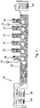
- the sheet-fed offset printing machine is for one-sided printing of substrates 02, z. B. formed by sheet 02, which are removed from a supply stack 03 and successively through four printing units 01, for example, for the colors cyan, magenta, yellow and black.
- an application device 04 is arranged inline to these printing units 01, on the sheet 02 a non-contact identification feature, such as an RFID system or a part of an RFID system such as an antenna of a transponder is applied.
- the RFID system preferably has a resonant frequency of 8.2 MHz or 13.56 MHz.
- the printing device 04 another, working by the offset printing unit 04, via which an electrically conductive material, in particular printing ink, which may be colored or transparent, in the form of electrical conductors, which may form an antenna of a transponder, is printed.
- the printing unit 04 can work according to another printing method, in particular after a gravure printing method or a high-pressure method.
- the identification features (or parts thereof) are first applied and then the sheet 02 is printed in multicolor printing, whereby the identification features can be colorless and the multicolor printing can overprint the identification features or not.
- an intermediate drying (not shown) can be provided between the application device 04 and the subsequent printing unit 01.
- the application device 04 could also be arranged behind the printing units 01 in the direction of transport of the sheets 02.
- the application device 04 may according to another, not shown embodiment also from z. B. three successive printing units, wherein in a first printing unit, an electrically semiconductive, preferably organic material such as electrically semiconductive polythropene or polymers or electrically conductive materials (such as copper, aluminum or silver) is printed in a second printing unit an electrically insulating material, preferably a polyolefin (for example polyethylene, polypropylene, ionomer, polystyrene, polyester, an ethylene-methacrylic acid copolymer) or polymers and in a third printing unit an electrically conductive material.
- an electrically semiconductive preferably organic material such as electrically semiconductive polythropene or polymers or electrically conductive materials (such as copper, aluminum or silver) is printed in a second printing unit an electrically insulating material, preferably a polyolefin (for example polyethylene, polypropylene, ionomer, polystyrene, polyester, an ethylene-methacrylic acid copo
- a printing unit 04 electrically semiconducting polymer and in another e.g. following printing unit 04 applied an electrically insulating polymer.
- an electrically conductive polymer preferably printed for the electrode structure.
- These polymers are preferably soluble in solvents intended for printing and thus e.g. B. usable as a printable ink.
- a finishing station 06 is arranged inline to the printing units 01, which may be, for example, a coating unit 06 or include.
- the printed sheets 02 which are provided with the non-contact identification feature or a plurality of such identification features, are extended via a delivery extension 07 to either one of two stacking stacks 08; 09, wherein, for example, the filing stack 08 for receiving waste paper and the filing stack 09 for receiving proper printed matter is determined so that the faulty sheet 02 can be sorted out
- the printed products may in particular be folding cartons or labels.
- the sheet 02 or cylinder of the printing units 01 or the application device 04 and the finishing station 06 are preferably dimensioned so that both in the axial direction of the cylinder or in the direction of the width of the sheet 02 and in the circumferential direction of the cylinder or in Lengthwise of the sheet 02 each have several benefits are provided. Accordingly, a plurality of identification features are applied to each sheet 02.
- the printing machine preferably comprises non-contact testing devices 10; 11 for examination the quality of the printed products or the function of the identification features applied thereon, wherein the functional test may also comprise a possibly required prior configuration, as will be explained in detail below.
- the testing devices 10; 11 may in particular the optical properties such. B. color and raster content of the printed image or form of the applied identification features and / or the electrical or electromagnetic properties of the identification features such as conductivity of the applied conductor tracks and / or frequency of the applied resonant circuit check, for example, by inductive means.
- the test device 10 which is arranged after the application device 04, may be an optical test device 10, which checks the applied identification features with respect to their optical characteristics.
- the test device 10 may be an electrical or electromagnetic test device 10, which checks the applied identification features with respect to their electrical and / or magnetic and / or electromagnetic properties.
- the test device 10 may be designed to check both the optical and the electrical or magnetic or electromagnetic properties of the identification features or two test devices 10 may be provided one behind the other, one for optical testing and one for electrical or magnetic or electromagnetic testing.
- test device 10 could also be arranged elsewhere within the printing press, for example following the last printing unit 01 seen in the conveying direction of the sheet 02 or following the finishing station 06. If intermediate drying takes place subsequently to the application device 04 the test device 10 are also arranged after the intermediate drying.
- the testing device 11 arranged downstream of the finishing station 06 which could also be arranged following the last printing unit 01, preferably comprises a visual inspection of the printed image applied by means of the printing units 01.
- this optical inspection may comprise a control of the coloration, and / or the color density and / or the register.
- the test device 11 can further include an optical test of the identification features, in particular if such an optical test has not been carried out in the test device 10.
- the test device 11 may also include an electrical or magnetic or electromagnetic test of the identification features, in particular if such a test has not been carried out in the test device 10 or if the test device 10 is not provided at this point. Accordingly, if appropriate, two or more testing devices 11 can also be connected in series.
- the checking device 11 may possibly also be arranged following the last printing unit 01, seen in the conveying direction of the sheet 02, or between this printing unit 01 and the finishing station 06.
- the test device 11 may, for example, as explained in more detail below, include a CCD area camera or a camera with a CMOS chip or a CCD line scan, as seen in the transport direction on the last printing unit 01, in particular on the impression cylinder 39 (see. Fig. 3 ), or is arranged on the coating unit 06.
- Fig. 2 Reference is made, the structure of which in large parts according to Fig. 1 corresponds, so that reference is made to the above description.
- an application device 12 z. B.
- an adhesive device 12 is provided on the parts of identification features, in particular chips of RFID systems, applied to the sheet 02, in particular glued, be.
- the sticking device 12 is arranged between the last printing unit 01 and the finishing station 06, but it could also be immediately following the last printing unit 01 (eg cooperating with its impression cylinder) or immediately after the finishing station 06 (eg cooperating with a cylinder thereof) or behind the finishing station 06.
- a further testing device 13 may be provided following the sticking device 12, which may also comprise a physical contacting of the chips by means of measuring tips.
- This test device 13 can also be designed so that it also contacts the applied in the application device 04 parts of the identification features for the purpose of verification, for example, to control the conductivity of the applied conductor tracks.
- Such a contacting test device 13 can alternatively or additionally also be arranged after the application device 04 (also in the case of the embodiment according to FIG Fig.1 ).
- each transponder is checked individually.
- each transponder is checked in two successive steps, namely a first step in which a transponder is configured and a second step in which the functions of the configured transponder are tested.
- the IC of the transponder can be electrically contacted with measurement probes provided for this purpose with measuring tips which are (indirectly) connected to a configuration data processing system. It is first checked by comparison with a reference voltage, whether a proper electrical contact exists; otherwise, the corresponding sheet 02 is assigned to the waste. The frequency of the antenna resonant circuit connected to the IC is then determined via a pulse width measurement by determining the number of oscillations of a reference signal during the measurement period and from this the frequency of the measurement signal is calculated.
- the identification data such as in particular the identification number and, if necessary, for a digital signature, a key is programmed, which is known only to the authenticated transponder and the reader (transmitting / receiving station).
- the (previously set) operating parameters are checked and the functions of the transponder are tested without contact.
- the transponder between a transmitting coil, which generates a continuous sine wave signal, and a receiver coil are arranged.
- the energy storage of the transponder is charged via the transmitting coil by means of an unmodulated sine signal.
- the required commands and data are sent to the transponder via a modulated sinusoidal signal.
- the transmission signal is switched off and the transponder now sends a frequency modulated response signal, which can be evaluated to verify the correct operation of the transponder and its parameters such. B. to calculate transmission frequency or transmission field strength.
- the quality of the transponder antenna resonant circuit can be determined by the fact that the antenna resonant circuit is excited to self-oscillation and appropriate conclusions are drawn from the exponential decay of the signal received at the receiver coil.
- the optical inspection or inspection device described below relates in particular to printed products produced in a rotary printing press in offset printing, but is at least mutatis mutandis applicable to other printing machines, for example in a steel engraving process, screen printing or hot stamping printing printing press.
- a usable in-line inspection system for assessing a quality of the printed product has at least one image recording unit 48, in particular a camera 48, preferably a color line camera system.
- the color line camera system preferably uses a color line camera 48 with e.g. B. 2,048 pixels per image line.
- the in-line inspection system for assessing the quality of the printed matter produced by the press is designed for in-line inspection and in-line color control on medium-format presses. In-line inspection means that a substrate is inspected during its transport through the press. The in-line inspection system ensures that operator-defined quality is maintained throughout the production process.
- the inline inspection system for assessing the quality of the printed product produced by the printing press essentially consists of three components: at least one image acquisition unit 48, a camera and lighting electronics unit and a control cabinet with an image processing system.
- the image pickup unit 48 is installed in the printing machine. It has z. B. a color line camera 48, a constant lighting or alternatively a flash lighting, in particular a triggered line lighting, on, both the constant light and the flashlamp lighting each several more side by side, d. H. have line-shaped, arranged light sources, wherein the illumination device in each case z. B. is cooled with water, and a rotary encoder, wherein the encoder z. B. has a resolution of 10,000 strokes.
- the camera and lighting electronics unit includes all necessary functional units for power supply of the lighting unit and the signal processing of the camera.
- This unit is placed near the image pickup unit 48 at a suitable location. It ensures a homogeneous illumination of the sheet transported by the printing press. With the help of a light measuring function z. B. cyclically checked whether the Bulbs flawless, ie work in their intended work area.
- the cabinet with the image processing system includes in particular z. B. a power supply of the image processing system and an image processing computer preferably including an interface for operation to a control center computer (TCP / IP) and the ability to connect a monitor, z. B. a color monitor, to monitor the printed products and error display during operation. In the case of an impression, a monitor switch is also provided.
- TCP / IP control center computer
- monitor switch is also provided.
- a user interface may initially be temporarily implemented on a second PC, before the operating software is integrated in a serial product in a control room assigned to the printing press.
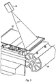
- illumination device 46 preferably generates a light strip 41 on a sheet transported by the printing cylinder 39 arc 02.
- the illumination device 46 is preferably within a part of the printing unit 01 of the printing machine surrounding protection 38, z. B. arranged below a tread 38 in the gallery area of the printing press.
- Light remitted by the illumination strip 41 is detected by a camera 48 arranged at a distance from the printing cylinder 39 within a specific detection angle ⁇ .
- the camera 48 detects light remitted by the illumination strip 41, preferably through a preferably narrow gap or slot in the protection 38 or foot step 38 covering the printing unit cylinder 39, this gap or slot extending transversely to the transport direction of the printing material 02.
- a so-called fault monitor is connected to a graphics card of an image processing system. This shows a live image of the camera 48.
- the print error display is superimposed on the camera image, so that the operator is immediately able to locate the location of the fault and, if necessary, the cause of the error.
- the fault monitor shows both on the substrate 02 briefly occurring printing errors, eg. As color splashes, water marks or paper defects, as well as permanent pressure variations, z. As an over- or under-dyeing of individual printing inks or toning on.
- a process learning mode is integrated, which is able to automatically learn the current quality standard during the good production. Programming a model is not necessary.
- references are generated, in particular for the color model and the intensity model, which are used for comparison for the inspection and color determination.
- the learning mode comprises the following functions: learning references, expanding learned or stored references, inputting the number of desired learning sheets, defining the window of the inspection area, displaying the learned or stored reference image, entering the mask for a non-inspected image area, editing the reference image, Editing and copying masks.
- the in-line inspection system is able to add permissible changes in production, which are rated as errors by the in-line inspection system, during production.
- the inline inspection system adapts adaptively to the current quality standard and controls or regulates z.
- the human eye is able to detect relatively small color changes.
- the color analysis model takes into account this physiological effect.
- the colors red, green and blue spanning the color space of the camera 48 are transformed into a color space, which is referred to as the counter-color model.
- the counter-color model corresponds to an electronic adjustment of human color perception.
- the counter-ink model can also be implemented on the basis of the offset printing inks CMYK, this color model being oriented towards a subtractive color mixing (printing method) compared to the color model according to the invention.
- Intensity deviations d. H. Changes in color density are detected by a gray value analysis. This method has particular in areas of uncoloured colors, in an over- and under-coloring and small errors, eg. As small splashes of paint or paper defects, its strengths.
- the inking unit for metering the amount of ink to be transferred to the substrate 02 can in the axial direction of a forme cylinder of a printing unit of the printing press more, z. B. at least between 25 and 60 zones, wherein the dosage the ink to be transferred to the substrate 02 is differently adjustable in different zones.
- the metering device of the inking unit can, for. B. controllable zone screws, wherein in a multi-color printing printing machine a total of several hundred each individually controllable zone screws can be provided.
- the metering device meters a quantity of the printing ink 02 to be transferred to the printing ink by adjusting its layer thickness and / or its application time.
- the metering device can also be used as an ink supply system using at least one paint pump, e.g. Example, as a Pumpfarbwerk be formed, wherein ink is brought to a Farbduktor an inking unit and the Farbduktor preferably zonally by means of individually acting on the different inking areas adjusting agent is metered, wherein the adjusting means z. B. a drivable by at least one electrically actuable actuator color dosing, z. B. at least one color meter or a paint slide, having the actuator z. B. is designed as a controllable by a control unit servomotor.
- the inking unit can be configured as a roller inking unit consisting of many rollers or as a short inking unit.
- the inking unit can also be designed as a spray-inking unit which atomises ink, preferably printing ink, on a paint ductor and sprays it on an ink fountain roller.
- Color control may be carried out by two different methods, depending on the specific circumstances of the case. If color gauges with sufficiently large color patches are present, the target densities for the individual colors are first entered using a colorimeter according to the color density control scheme. The position of the measurement control strip is marked by the operator on the monitor. Thereafter, the fields of the strip are automatically analyzed with respect to scale colors and the respective actual density is determined. Special colors are to be marked by the operator in the measuring strip. Based on the deviations from a nominal density and the present actual density, the ink zones are placed on an inking unit of the printing press. The respective deviations are displayed graphically and numerically. The inline inspection system specifies default values for the ink zone position. These can either be taken over manually or used fully automatically in a closed loop. With the aid of the color measuring strips, the tonal value increase can also be determined with the aid of the grids.
- the algorithms for density determination in color measurement strips can be run through for each sheet 02. A sliding averaging of the measured values over any number of sheets is also possible. Measurement inaccuracies caused by the influence of variations in pressure, by a noise of the camera 48, z. As a photon noise or quantization noise of the AD converter, or caused by an instability of the radiated light from the illumination device are reliably eliminated in this way, or at least minimized in their interference.
- a calibration of the density measuring system is carried out with measuring sheets, which are driven through the machine at regular intervals. Calibration automatically adjusts a color balance, contrast and brightness. Furthermore, the standard light can be set for the measurement, z. B. as usual D50 or D65. Re-calibration is usually not needed more often in practice than once a week.
- the measuring strip has a field width and a field height in each case z. B. from about 5 mm to 6 mm.
- the size of the measuring field required by a 2 ° standard observer must be safely accommodated in the measuring field.
- the measuring strip consists of several equal segments, whereby a regular structure within a segment takes place.
- Another method of color control provides a color determination and color control based on the printed image. Prerequisite for this is preferably that the area coverage per ink with a resolution of 10 ⁇ dpi ⁇ 40 from a precursor, z. CIP3, and "significant" print areas per color zone or ink zone area are present. Significant are print areas when one of the inks in this area is dominant. The determination of the significant pressure ranges is carried out automatically by evaluation of data from the preliminary stage.
- the color determination and the derivation of manipulated variables for the color control takes place on the basis of the printed image itself. To this end, a transformation of the camera image data in the CMYK space is performed.
- the analysis of the printed image is based on a color integration of the significant pressure areas within longitudinal strips, which preferably correspond in number to the number of zone screws. These stripes are again divided horizontally. Within these surfaces, the corresponding zone is set based on the color changes and the zone density. By appropriate averaging over several sheets 02 allowable process fluctuations are compensated.
- a colorimetric error calculated from the measurement is converted for each color zone into a control command for activating the zone screw in question.
- a change in the ink supply within the press takes a certain amount of time before it becomes visible in the print image. This behavior is due to the nature of the ink transfer in the printing press.
- an integral controller with a proportional component in short PI controller, is provided as controller.
- This regulator has the advantage that, in addition to a stationary component (I component), an error-proportional component provides additional / reduced ink supply for a certain time and thus speeds up the control process.
- control loop is simplified in that a cyclic method with the steps of measuring, setting and maintenance is realized. After completion of the waiting period, d. H. after a certain number of cylinder revolutions, a new cycle is started with a new measurement.
- the relevant time constant is determined by the time between the position of the zones and a reaction on the paper. Since this time z. B. is proportional to several ten arc, an open principle of action is realized here.
- the control itself is executed as a position control, d. H. the opening of the individual zones is set and kept in this position for a certain time. In order to achieve the desired density as quickly as possible, it is permitted that, in the case of a paint feed, the zones may be over-regulated for a certain time.
- correction values i. H. Setpoints to enter for the zone screws. These changes are treated in the signal flow as a control deviation.
- the control algorithm integrates all parameters influencing the color scheme. These include in particular the color behavior, d. H. a coverage of the color, the paper behavior and the ink transfer behavior of the ink fountain. Here the color and the paper are order-dependent parameters.
- the preferably digitally working image recording unit 48 comprises z. B. a specially developed for a printing machine lighting unit and a color CCD line scan camera.
- the lens is specially adapted to the high resolution camera 48, has a removable filter, for. B. a UV filter as a lens protection and can be adjusted user-friendly. In case of service, the camera 48 and the lens can be easily replaced.
- the image pickup unit 48 is protected against mechanical and electromagnetic interference.
- z. B. specially developed for this application developed high frequency clocked lighting sources.
- the arrangement of the lamps within the lighting unit is z. B. specially adapted for application in sheetfed printing. The bulbs can be easily exchanged.
- the image capture module converts the incoming video image into a digital video stream.
- This video stream undergoes brightness correction (shading correction), perceptual color matching and color space transformation in the frame grabber.
- This digital video stream is stored in the memory area of the image acquisition module for later processing.
- the image acquisition and image evaluation is performed in machine real time.
- the inline inspection system is z. B. equipped with a positioning unit, which is able to make an image positioning. By blurring in the transport movement of the sheet 02, it may be necessary to position the recorded print image for each shot in the in-line inspection system. During the learning process, a reference position for each arc is automatically determined in the inline inspection system.
- the in-line inspection system captures sheet 02 with the CCD camera during production and forms a computer model with all variants of acceptable print quality. Based on a correct color setting, printed sheets or printed copies are recorded, analyzed and evaluated in the learning phase.
- the learning mode is able to generate references in machine real time. After learning, the in-line inspection system automatically switches to color measurement and inspection mode. With the help of the learned references, the current production is now being tested. However, it is possible at any time to expand a standard within the reference memory by teaching.
- the RGB signal of the video camera is converted into the color separations CMYK. Each color separation is divided into strips, corresponding to the color zones. Within each zone, the area fraction of the relevant color separation is determined. This value is averaged over the recorded sheets 02. The average value of each area component from the learning phase is taken as the setpoint for the control phase.
- each image is compared with the analysis models and references.
- the sensitivity of the in-line inspection system may be reduced by the operator using fewer inspection parameters, such as: As the gray scale and color tolerances and error sizes are adjusted to the individual needs.
- the inspection mode includes z. For example, the following functions: continuous inspection of the current production order, input of tolerances for the inspection, defining a grid for the horizontal and vertical division of the inspection image.
- the entry of inspection parameters that influence the in-line inspection system can optionally be secured by a "password".
- the "Password" can be changed or several user-specific "Passwords" can be assigned.
- During the inspection can z.
- B. Separately up to 96 individual benefits through the inspection system grid can be recorded statistically. Error benefits are characterized by a grid frame adapted to the optical conditions.
- the error analysis processor analyzes the image comparison generated by the image processor. It generates a fault image, which is displayed in the live image of the fault monitor. This allows the operator to intervene in the machine process immediately after analyzing the image.
- a human-machine interface is implemented, all of whose connections are preferably via optocouplers.
- the interface is z.
- the in-line inspection system is preferably equipped with a hard disk storage that has enough capacity to store various jobs including all tolerances and statistics.
- This order memory is z. B. designed for about 2,000 jobs. With a hard disk extension, the number of jobs can be increased accordingly.
- the image comparison is performed in machine real time z. B. up to a speed of 18,000 sheets per hour.
- error size can be at least one pixel.
- the machine interface sends an alarm when one or more consecutive sheets 02 have been identified with printing errors.
- a distinction is made as to whether it is a color deviation that leads to a zone screw adjustment, or whether it is a geometric error, d. H. a short-term error.
- z For example, information about whether there is a good or bad bow, the in-line inspection system is active, or is in learning mode is available at PLC outputs.
- the in-line inspection system stops after a failure and in the other mode the in-line inspection system only temporarily stops.
- the image of the sheet 02 including the error display is frozen as soon as the in-line inspection system detects an error on a sheet 02.
- the operator can look at the error display at rest and evaluate and possibly verifying with associated sheet.
- the frozen image must be released again by pressing a button.
- the inspection continues in the background.
- stop-and-continue mode the image is automatically frozen after an error detection and, after an adjustable duration of, for example, 10 sec. B. about 15 seconds automatically released again. The operator thus has the opportunity to view the image for a certain amount of time without being forced to manually unlock the in-line inspection system.
- each sheet 02 is analyzed and a good, warning and bad bow statistics are kept. Furthermore, all relevant parameters of a production are recorded and transferred to the statistics module. Since statistics are kept on a PC, it is possible to process them with commercially available programs.
- the inline inspection system can measure any sheet size with an edge length of z. B. inspect up to 740 mm x 1050 mm.
- Tolerance values of the individual processing areas of a reference image can be displayed numerically and, if necessary, changed.
- the minimum number of pixels that will fail as an error for an out of tolerance error area can be entered.
- the following section deals with the operating concept of the inline inspection system.
- the in-line inspection system is designed to allow easy and fast operation, which brings great benefits to the printer with little training required. He must be informed early on an incipient deviation before waste is generated.
- the operation exists as a task on the machine control station, which fits into the superordinate operating concept of the machine. For viewing a current defect image, an additional monitor is available. In the case of a double-sided printing press, the image can be switched.
- the beyond the inspection operation beyond functions such. B. for setting up a job or a creation of masks, z. B. accessible via corresponding entry points in the existing, implemented in the machine control operating software of the machine.
- the image is preferably taken while the substrate to be inspected 02, z. B. sheet 02 or web is located on a printing cylinder of the printing press.
- the image capture is very stable here. Depending on the material, for. B. very thin paper, but it may cause wrinkling or z. B. come in a rigid cardboard to a detachment of the sheet end on the outer surface of the printing cylinder.
- the image acquisition is mechanically calibrated during installation, so that known mechanical boundary conditions are to be converted directly into the pixel dimension of the image acquisition.
- a data flow to or from the machine control center provides that a job name, a load number or the pass are taken directly from the machine control center in order to be used for the job management of the inline inspection system. From the arc dimensions, the higher-level inspection window can be generated. The manually operated good sheet signal on the machine can be used to activate the inspection and also for the statistical evaluation. If necessary, a "good-sheet counter" generated by the in-line inspection system can be supplied to the machine control station statistics.
- a job name For example, a job name, a job number, a load number, an inspection frame derived from the paper format, or a benefit distribution, e.g. B. from a CF2 file of a punching contour.
- a benefit distribution e.g. B. from a CF2 file of a punching contour.
- Manual entries which mean an expense for the printer, are limited to the entry of the positioning window.
- the inspection window can also be set automatically, whereby it is then not necessary to have to start the printing press to set up the job.
- the learning can then - with active good bow signal - be started automatically.
- Inspection and control room software share a control panel.
- the control console software is displayed;
- hardkeys or function keys are available in the control console software screens. For example, functions for switching front / back, Live / Stop & Go / StopOnError or "Freeze".
- a soft key can also be used to activate the look-and-feel of the control console software; This then provides the full operability of the inline inspection system. In this mode, with respect to the operation of the printing press only the status information, the z. B. displayed in an upper status window shown.
- Settings that are to be made in the inspection user interface via the function key sequence implemented analogously to the control console software relate, for example, to Tolerances, learning / learning, creating masks, customizing the utility, adjusting the inspection framework, re-defining the positioning window, or loading or viewing images.
- the live monitor can display error displays in the color area CMYK or spot colors by corresponding color display.
- Additional controls in the control room software may provide for a correction of a net counter by the inspection result, an error signature statistics or a traffic light indication of the inspection in the machine status field.
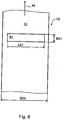
- a in the Fig. 6 illustrated arc 02 moves with a surface 42 in a direction indicated by an arrow movement direction 44.
- the sheet 02 is in particular as a z. B. paper or cardboard existing substrate 02 forms, in particular for the production of labels or cartons.
- the width B01 of the illumination strip 41 is preferably directed along the direction of movement 44 of the sheet 02, whereas the length L01 of the illumination strip 41 is preferably parallel to the width B03 of the sheet 02, ie transverse to the direction of movement 44 of the sheet 02, and over parts of the width B03 of the arc 02 or over its entire width B03 can extend.
- the width B01 of the illumination strip 41 is preferably at least 3 mm, in particular 8 mm.
- the direction of movement 44 of the arc 02 is thus preferably directed at least substantially parallel to the width B01 of the illumination strip 41, the direction of movement 44 of the arc 02 being within the plane spanned by the length L01 and the width B01 of the illumination strip 41.
- the arc 02 is preferably not arched at least in the region of the illumination strip 41.
- the illumination device 46 has a plurality of light sources 47 arranged next to each other in line form, so that the entire illumination device 46 is formed in a line-shaped manner.
- Light sources 47 of the illumination device 46 are preferably arranged parallel to the length L01 of the illumination strip 41.
- the light sources 47 have to the surface 42 of the sheet 02 each have a distance A07, wherein the distance A07 is preferably between 30 mm and 200 mm, in particular between 80 mm and 140 mm.
- the distance A07 of the light sources 47 is preferably perpendicular to the surface 42 of the sheet 02. All light sources 47 of the illumination device 46 are preferably formed similar, z.
- a central plane of the light emitted by the juxtaposed light sources 47 of the illumination device 46 and a central plane of the light reflected from the illumination strip 41 to the camera 48 include a preferably acute angle ⁇ with each other, the z. B. in the range between 15 ° and 60 °, in particular between 20 ° and 30 ° ( Figure 3 ).
- the lighting device 46 and groups of a plurality of line-shaped juxtaposed light sources 47 may be provided, wherein the individual groups of light sources 47 in their optical properties, eg. B. differ in the wavelength of the light emitted by them. So z.
- one group of light sources 47 emit white light
- another group of light sources 47 emit monochromatic light.
- the control device 23 can control a group of light sources 47 independently of at least one other group of light sources 47 in their brightness and / or illumination duration.
- the illumination strip 41 is arranged outside of a focal point of the light emitted by the light sources 47 in the direct or in the deflected beam path.
- the lighting device 46 consists z. Example, of a plurality of row-like juxtaposed modules each having preferably a plurality of line-shaped juxtaposed light sources 47, wherein a parting line 26 between two adjacent modules is preferably arranged obliquely to the length L01 of the illumination strip 41.
- the individual modules of the lighting device 46 may, for. B. be functionally identical. So z. B.
- one of the width B03 of the arc to be illuminated 02 corresponding line length of the plurality of juxtaposed modules composed lighting device 46 can be activated by switching on the line-shaped light sources 47 of the affected modules or it can be one of the length L01 of the lighting strip 41 corresponding line length of a plurality of juxtaposed modules composed lighting device 46 are activated by switching on the line-shaped light sources 47 of the affected modules.
- Fig. 8 shows in a two-dimensional representation, a single light source 47 of the illumination device 46.
- the light source 47 emits its light in a solid angle ⁇ , the solid angle ⁇ spans a cut out of a sphere surface AK, ie a spherical surface AK, up to the size of a hemisphere.
- Fig. 9 shows several, z. B. four in the Fig. 8 shown light sources 47 arranged in rows next to each other on a common board 21.
- the current source 22 belonging to the respective light sources 47 is arranged on the same board 21.
- the current source 22 is preferably designed as a constant current source 22, in particular as a controllable constant current source 22.
- the optical inline inspection system includes - like the Fig. 7 can be removed - and a detection device 48 with at least one arranged at a distance A09 from the surface 42 of the sheet 02 detector 49, wherein the detector 49 detected by the surface 42 of the sheet 02 remitted light.
- the distance A09 is in the range between 10 mm and 1,500 mm, preferably between 50 mm and 400 mm.
- the detection device 48 is z. B. as a camera 48, preferably a line scan camera 48, in particular a color line camera 48 is formed.
- the detection device 48 may have a plurality of juxtaposed detectors 49, wherein the line-shaped arranged detectors 49 are preferably arranged parallel to the length L01 of the illumination strip 41.
- the detector 49 of the detection device 48 may, for. B. may be formed as a CCD array 49 or as a group of photodiodes 49.
- the detector 49 of the detection device 48 converts the detected remitted light into an electrical signal and supplies the electrical signal for its evaluation to an image processing device 24 connected to the detection device 48.
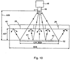
- Fig. 10 shows a view of the optical inspection system in a direction perpendicular to the direction of movement 44 of the sheet 02 plane.
- the illumination device 46 and the illumination strip 41 illuminated on the surface 42 of the arc 02 are arranged parallel to one another at a distance A07, however, an extension of the illumination device 46, ie its length B06, can be greater than the length L01 of the illumination strip 41 or the width B03 of the arc 02.
- the illumination device 46 is preferably divided into a plurality of modules, ie in this example arranged in five rows next to one another, wherein the light sources 47 arranged in each module emit light in each case to the illumination strip 41.
- the light reflected by the illumination strip 41 is detected by the detector 49 of the detection device 48 arranged at a distance A09 from the surface 42 of the arc 02 within a spatial detection angle ⁇ opening longitudinally to the length L01 of the illumination strip 41, the detection angle ⁇ in this example being such is dimensioned to detect the light reflected from the illumination strip 41 over the entire length L01 of the illumination strip 41.
- the detection angle ⁇ forms a cross-sectional area on the surface 42 of the arc 02, so that the detection angle ⁇ detects at least a part of a cross-sectional area of the light-emitting beam emitted by the illumination device 46 extending across the width B01 of the illumination strip 41.
- the cross-sectional area detected by the detection angle ⁇ is preferably at least as large as the area spanned on the surface 42 of the arch 02 by the length L01 and width B01 of the illumination strip 41.
- the quality of an image recorded with the detection device 48 by detecting the light reflected from the illumination strip 41 is significantly dependent on the light sources 47 of the illumination device 46 emitting light of constant intensity. Because fluctuations in the light intensity of the light emitted by the light sources 47 result in the detection device 48 with respect to the signal supplied to the image processing device 24 to the same result as changes in the nature of the surface 42 of the illuminated sheet 02, so in the image processing device 24, the causes of a signal change not can be distinguished. Under these circumstances, it is not possible to obtain any reliable statements about the nature of the surface 42 of the illuminated sheet 02 from an image analysis carried out in the image processing device 24.
- the light sources 47 used in the illumination device 46 are preferably designed as high-intensity light-emitting diodes 47 or laser diodes 47 whose light intensity is temperature-dependent.
- measures for stabilizing the temperature of the light sources 47 arranged on the board 21 are described in order to achieve a constant light intensity.
- the advantage of this solution is that the thermal load of the light sources 47 is dissipated directly at the point of origin, which can achieve short control times.
- the light sources 47 are preferably arranged on a circuit board 21 which can be equipped with further electronic components and is provided with conductor tracks.
- the semiconductor of the LEDs 47 or laser diodes 47 is preferably in direct physical contact with the board 21, the z. B. as MCPCB (metal core printed circuit board) or as a circuit board 21 is formed with a core of aluminum and on its light emitting diodes 47 or laser diodes 47 bearing mounting side to form a very low heat transfer resistance has only a very thin support on its heat-conducting substrate ,
- the optical inspection system is designed such that of the moving sheet 02 a useful image recording is possible. It should be noted that with a detection device 48 designed as a line camera 48, the detected amount of light reflected from the surface 42 of the moving sheet 02 changes depending on the speed of the moving sheet 02. This also changes the brightness of the image recording. With larger changes in speed, as they usually occur in the mentioned machines, the image acquisition can be unusable.
- a switch-on duration t3 of a single light source 47 or a group of light sources 47 of the lighting device 46 which is controlled by a current source 22 controlled by the control device 23,
- a constant current source 22 are controlled to synchronize with a triggering, ie an exposure time t1 of the line scan camera 48, so that the surface 42 of the moving sheet 02 regardless of the speed of the moving arc 02 is always illuminated with the same amount of light. This results in a constant brightness for the image taken by the line camera 48 over a wide range of the speed of the moving sheet 02.
- a plurality of groups of light sources 47 are provided in the illumination device 46, to each of which at least one current source 22, in particular a constant current source 22, is assigned.
- the switch-on times t3 of the light sources 47 are controlled by the control device 23 connected to the illumination device 46.
- the setting of a light quantity profile, preferably along the length L01 of the illumination strip 41, has the advantage that transmission losses can be compensated for by an optical system (not shown) of the line scan camera 48.
Landscapes
- Engineering & Computer Science (AREA)
- Manufacturing & Machinery (AREA)
- Microelectronics & Electronic Packaging (AREA)
- Quality & Reliability (AREA)
- Inking, Control Or Cleaning Of Printing Machines (AREA)
- Printing Methods (AREA)
- Ink Jet (AREA)
- Investigating Materials By The Use Of Optical Means Adapted For Particular Applications (AREA)
- Application Of Or Painting With Fluid Materials (AREA)
- Making Paper Articles (AREA)
Abstract
Description
Die Erfindung betrifft eine Druckmaschine und ein Verfahren zur Herstellung eines Druckerzeugnisses gemäß dem Oberbegriff des Anspruchs 1 oder 34.The invention relates to a printing press and to a method for producing a printed product according to the preamble of claim 1 or 34.
Insbesondere betrifft die Erfindung diejenige Technologie, bei der ein berührungsloses Identifikationsmerkmal wie insbesondere ein RFID-System (RFID = Radio Frequency Identification) bzw. ein Teil hiervon zum Zwecke der elektronischen Etikettierung von Objekten wie beispielsweise Verpackungen auf einen Bedruckstoff wie beispielsweise ein Etikett oder direkt auf eine Verpackung aufgebracht wird (elektronische Etikettierung mittels so genannter Smart Labels). Das zentrale Element eines RFID-Systems ist ein Transponder, der mittels Funkwellen beispielsweise im Langwellenbereich Daten mit einer Sende-/Empfangsstation austauscht. Die wesentlichen Komponenten eines Transponders sind insbesondere ein integrierter Schaltkreis zur Steuerung der Transponderfunktionen und ein Antennenschwingkreis für den Empfang und das Senden von Funkwellen. Passive Transponder weisen keine eigene Energieversorgung auf, sondern beziehen ihre Energie aus dem Sendesignal der Sende-/Empfangsstation.In particular, the invention relates to that technology in which a contactless identification feature such as in particular an RFID (RFID = Radio Frequency Identification) system or a part thereof for the purpose of electronic labeling of objects such as packaging on a substrate such as a label or directly on a packaging is applied (electronic labeling by means of so-called smart labels). The central element of an RFID system is a transponder, which exchanges data with a transmitting / receiving station by means of radio waves, for example in the long-wave range. The essential components of a transponder are in particular an integrated circuit for controlling the transponder functions and an antenna resonant circuit for the reception and transmission of radio waves. Passive transponders do not have their own power supply, but draw their energy from the transmission signal of the transmitting / receiving station.
Ein RFID-System ermöglicht somit mittels der Transponder-Technologie eine berührungslose, drahtlose Identifikation von Produkten wie beispielsweise Verpackungen, wobei anstelle von oder zusätzlich zu Identifizierungsdaten auch andere, komplexere Daten wie beispielsweise Verkaufspreise, Herstellungsdaten, Verfallsdaten, Herstellungsort, Verschlüsselungsdaten u. dgl. übertragen werden können.An RFID system thus enables non-contact, wireless identification of products such as packaging by means of the transponder technology, whereby instead of or in addition to identification data, other, more complex data such as selling prices, manufacturing data, expiration dates, place of manufacture, encryption data u. Like. Can be transmitted.
Aus der
Aus der
Aus der
Aus der
Die
Die
Die
Die
Der Erfindung liegt die Aufgabe zugrunde, eine Druckmaschine und ein Verfahren zur Herstellung eines Druckerzeugnisses zu schaffen.The invention has for its object to provide a printing machine and a method for producing a printed product.
Die Aufgabe wird erfindungsgemäß durch die Merkmale des Anspruchs 1 oder 34 gelöst.The object is achieved by the features of claim 1 or 34.
Die mit der Erfindung erzielbaren Vorteile bestehen insbesondere darin, dass aufgrund der in die Druckmaschine vorzugsweise inline integrierten Prüfeinrichtungen, die zusätzlich zur Prüfung der Identifikationsmerkmale vorzugsweise auch zur Überprüfung des Druckbildes ausgelegt sein können, auf vergleichsweise einfache Weise Identifikationsmerkmale wie insbesondere RFID-Systeme tragende Druckerzeugnisse von insgesamt hoher Qualität bzw. mit niedriger Fehlerquote erzeugt werden können.The achievable with the present invention consist in particular that due to the preferably inline into the printing machine integrated testing facilities, which may be designed to check the print image in addition to checking the identification features, in a relatively simple way identification features such as RFID systems bearing particular printed products high quality or with a low error rate can be generated.
Ausführungsbeispiele der Erfindung sind in den Zeichnungen dargestellt und werden im Folgenden näher beschrieben.Embodiments of the invention are illustrated in the drawings and will be described in more detail below.
Es zeigen:
- Fig. 1
- ein erstes Ausführungsbeispiel einer Druckmaschine in Seitenansicht in halbschematischer Darstellung;
- Fig. 2
- ein zweites Ausführungsbeispiel einer Druckmaschine in Seitenansicht in schematischer Darstellung;
- Fig. 3
- die Anordnung eines Inline-Inspektionssystems in einer Druckmaschine nach
Fig. 1 oder2 ; - Fig. 4
- eine perspektivische Darstellung des Inline-Inspektionssystems nach
Fig. 3 in der Druckmaschine; - Fig. 5
- eine weitere perspektivische Darstellung des Inline-Inspektionssystems nach
Fig. 3 in der Druckmaschine; - Fig. 6
- eine Draufsicht auf einen in einer Druckmaschine nach
Fig. 1 oder2 bewegten Bedruckstoff mit einem Beleuchtungsstreifen; - Fig. 7
- eine Seitenansicht eines weiteren Inline-Inspektionssystems einer Druckmaschine nach
Fig. 1 oder2 . - Fig. 8
- eine einzelne Lichtquelle der Beleuchtungseinrichtung des Inline-Inspektionssystems nach
Fig. 7 ; - Fig. 9
- eine Seitenansicht des Inline-Inspektionssystems.
- Fig. 1
- a first embodiment of a printing press in a side view in semi-schematic representation;
- Fig. 2
- a second embodiment of a printing machine in side view in a schematic representation;
- Fig. 3
- the arrangement of an inline inspection system in a printing machine according to
Fig. 1 or2 ; - Fig. 4
- a perspective view of the inline inspection system according to
Fig. 3 in the printing press; - Fig. 5
- another perspective view of the inline inspection system according to
Fig. 3 in the printing press; - Fig. 6
- a plan view of a in a printing press according to
Fig. 1 or2 moving substrate with a lighting strip; - Fig. 7
- a side view of another inline inspection system of a printing machine according to
Fig. 1 or2 , - Fig. 8
- a single light source of the illumination device of the inline inspection system
Fig. 7 ; - Fig. 9
- a side view of the inline inspection system.
Es wird zunächst auf
Die Offsetrotationsdruckmaschine gemäß dem gezeigten Ausführungsbeispiel arbeitet im Vierfarbendruck. Es versteht sich, dass ebenso Ausführungsformen möglich sind, bei denen die Druckmaschine zum Verdrucken von mehr oder weniger Farben ausgebildet ist.The offset rotary printing machine according to the embodiment shown operates in four-color printing. It is understood that embodiments are also possible in which the printing press is designed to print more or less colors.
Die Bogenoffsetdruckmaschine gemäß
Es werden somit im Falle der beschriebenen Druckmaschine zunächst die Identifikationsmerkmale (bzw. Teile hiervon) aufgebracht und dann der Bogen 02 im Mehrfarbendruck bedruckt, wobei die Identifikationsmerkmale farblos sein können und der Mehrfarbendruck die Identifikationsmerkmale überdrucken kann oder auch nicht. Zwischen der Applikationseinrichtung 04 und dem anschließenden Druckwerk 01 kann bei Bedarf eine Zwischentrocknung (nicht dargestellt) vorgesehen sein. Grundsätzlich könnte die Applikationseinrichtung 04 in Transportrichtung der Bogen 02 gesehen auch hinter den Druckwerken 01 angeordnet sein.Thus, in the case of the described printing machine, the identification features (or parts thereof) are first applied and then the
Die Applikationseinrichtung 04 kann gemäß einem weiteren, nicht dargestellten Ausführungsbeispiel auch aus z. B. drei hintereinander geschalteten Druckwerken bestehen, wobei in einem ersten Druckwerk ein elektrisch halbleitfähiges, vorzugsweise organisches Material wie beispielsweise elektrisch halbleitfähige Polythropen oder Polymere oder elektrisch leitende Materialien (wie z. B. Kupfer, Aluminium oder Silber) verdruckt wird, in einem zweiten Druckwerk ein elektrisch isolierendes Material, vorzugsweise ein Polyoletin (beispielsweise Polyethylen, Polypropylen, lonomer, Polystyrol, Polyester, ein Ethylen-Methacryl-Säure-Copolymer) oder Polymeren und in einem dritten Druckwerk ein elektrisch leitfähiges Material. Auf diese Weise können auf den Bedruckstoff aktive Bauelemente z. B. in Form von Transistoren aufgedruckt werden, die zu Halbleiterchips verschaltet sein können.The
Vorzugsweise wird in einem Druckwerk 04 elektrisch halbleitendes Polymer und in einem anderen z.B. nachfolgendem Druckwerk 04 ein elektrisch isolierendes Polymer aufgebracht. Wahlweise kann zusätzlich in einer weiteren oder mehreren weiteren Druckwerken 04 ein elektrisch leitfähiges Polymer, vorzugsweise für die Elektrodenstruktur aufgedruckt werden.Preferably, in a
Diese Polymere sind vorzugsweise in für Druck bestimmten Lösungsmittel löslich und somit z. B. als druckbare Tinte verwendbar.These polymers are preferably soluble in solvents intended for printing and thus e.g. B. usable as a printable ink.
In Transportrichtung der Bogen 02 gesehen nach den Druckwerken 01 ist inline zu den Druckwerken 01 eine Finishing-Station 06 angeordnet, die beispielsweise ein Lackwerk 06 sein bzw. umfassen kann. Anschließend an die Finishing-Station 06 werden die bedruckten und mit dem berührungslosen Identifikationsmerkmal bzw. mehreren solcher Identifikationsmerkmalen versehenen Bogen 02 über eine Auslageverlängerung 07 auf wahlweise einem von zwei hintereinander geschalteten Ablagestapeln 08; 09 abgelegt, wobei beispielsweise der Ablagestapel 08 zur Aufnahme von Makulatur und der Ablagestapel 09 zur Aufnahme von ordnungsgemäßen Druckerzeugnissen bestimmt ist, so dass die fehlerhaften Bogen 02 aussortiert werden könnenIn the transport direction of the
Die Druckerzeugnisse können insbesondere Faltkartons oder Etiketten sein. Die Bogen 02 bzw. Zylinder der Druckwerke 01 bzw. der Applikationseinrichtung 04 und der Finishing-Station 06 sind vorzugsweise so dimensioniert, dass sowohl in axialer Richtung der Zylinder bzw. in Richtung der Breite der Bogen 02 als auch in Umfangsrichtung der Zylinder bzw. in Längsrichtung der Bogen 02 jeweils mehrere Nutzen vorgesehen sind. Dementsprechend wird auf jeden Bogen 02 eine Vielzahl von Identifikationsmerkmalen aufgebracht.The printed products may in particular be folding cartons or labels. The
Die Druckmaschine umfasst vorzugsweise berührungslos arbeitende Prüfeinrichtungen 10; 11 zur Prüfung der Qualität der Druckerzeugnisse bzw. der Funktion der hierauf aufgebrachten Identifikationsmerkmale, wobei die Funktionsprüfung auch eine etwa erforderliche vorherige Konfiguration umfassen kann, wie weiter unten im Einzelnen beschrieben erläutert wird. Die Prüfeinrichtungen 10; 11 können insbesondere die optischen Eigenschaften wie z. B. Farbe und Rasterhaltigkeit des Druckbildes oder Form der aufgebrachten Identifikationsmerkmale und/oder die elektrischen bzw. elektromagnetischen Eigenschaften der Identifikationsmerkmale wie Leitfähigkeit der aufgebrachten Leiterbahnen und/oder Frequenz des aufgebrachten Schwingkreises prüfen, beispielsweise auf induktivem Wege.The printing machine preferably comprises
Im Falle des Ausführungsbeispiels gemäß
Grundsätzlich könnte die Prüfeinrichtung 10 auch an anderer Stelle innerhalb der Druckmaschine angeordnet sein, beispielsweise im Anschluss an das in Förderrichtung der Bogen 02 gesehen letzte Druckwerk 01 oder im Anschluss an die Finishing-Station 06. Falls anschließend an die Applikationseinrichtung 04 eine Zwischentrocknung erfolgt, kann die Prüfeinrichtung 10 auch im Anschluss an die Zwischentrocknung angeordnet werden.In principle, the
Die im Anschluss an die Finishing-Station 06 angeordnete Prüfeinrichtung 11, die auch im Anschluss an das letzte Druckwerk 01 angeordnet sein könnte, umfasst vorzugsweise eine optische Prüfung des mittels der Druckwerke 01 aufgebrachten Druckbildes. Diese optische Prüfung kann insbesondere eine Kontrolle der Farbgebung, und/oder der Farbdichte und/oder des Registers umfassen. Die Prüfeinrichtung 11 kann weiterhin eine optische Prüfung der Identifikationsmerkmale mit umfassen, insbesondere dann, wenn eine solche optische Prüfung in der Prüfeinrichtung 10 nicht erfolgt ist. Auch kann die Prüfeinrichtung 11 ggf. eine elektrische bzw. magnetische bzw. elektromagnetische Prüfung der Identifikationsmerkmale mit umfassen, insbesondere dann, wenn eine solche Prüfung in der Prüfeinrichtung 10 nicht erfolgte oder die Prüfeinrichtung 10 an dieser Stelle nicht vorgesehen ist. Dementsprechend können ggf. auch zwei oder mehr Prüfeinrichtungen 11 hintereinander geschaltet sein.The
Auch ist es möglich, unterschiedliche Eigenschaften der Identifikationsmerkmale an unterschiedlichen Stellen bzw. in unterschiedlichen Prüfeinrichtungen 10; 11 zu kontrollieren, beispielsweise die Resonanzfrequenzen der Schwingkreise in der Prüfeinrichtung 10 und die elektrischen Eigenschaften der Leiterbahnen in Prüfeinrichtung 11.It is also possible different properties of the identification features at different locations or in
Die Prüfeinrichtung 11 kann ggf. auch im Anschluss an das in Förderrichtung der Bogen 02 gesehen letzte Druckwerk 01 bzw. zwischen diesem Druckwerk 01 und der Finishing-Station 06 angeordnet sein. Die Prüfeinrichtung 11 kann beispielsweise, wie weiter unten näher erläutert, eine CCD-Flächenkamera oder eine Kamera mit CMOS-Chip oder eine CCD-Zeilenkamera umfassen, die in Transportrichtung gesehen am letzten Druckwerk 01, insbesondere an dessen Gegendruckzylinder 39 (vgl.
Es wird nun auf das Ausführungsbeispiel gemäß
Zur Überprüfung der elektrischen/elektronischen Funktionen dieser Chips kann eine weitere Prüfeinrichtung 13 im Anschluss an die Aufklebeinrichtung 12 vorgesehen sein, welche auch eine physische Kontaktierung der Chips mittels Messspitzen umfassen kann. Diese Prüfeinrichtung 13 kann auch so ausgebildet sein, dass sie ebenfalls die in der Applikationseinrichtung 04 aufgebrachten Teile der Identifikationsmerkmale zum Zwecke der Überprüfung kontaktiert, beispielsweise, um die Leitfähigkeit der aufgebrachten Leiterbahnen zu kontrollieren. Eine solche kontaktierende Prüfeinrichtung 13 kann alternativ oder zusätzlich auch im Anschluss an die Applikationseinrichtung 04 angeordnet werden (auch im Falle des Ausführungsbeispiels nach
Im Folgenden wird eine Möglichkeit einer Überprüfung der elektrischen bzw. elektronischen bzw. elektromagnetischen Eigenschaften eines auf die Bogen 02 aufgebrachten RFID-Systems mittels der Prüfeinrichtungen 10 bzw. 11 bzw. 13 beispielsweise erläutert. Es wird davon ausgegangen, dass jeweils ein vollständiger Transponder aufgebracht wurde, also ein Antennenschwingkreis zum Senden bzw. Empfang von Funkwellen und ein IC zur Steuerung der Funkwellen. Falls beispielsweise nur der jeweilige Antennenschwingkreis aufgebracht wird, versteht es sich, dass die entsprechende IC-Prüfung entfällt. Auch kann es ausreichend sein, nur eine der mehreren möglichen prüfbaren Funktionen zu überprüfen.In the following, a possibility of checking the electrical or electronic or electromagnetic properties of an RFID system applied to the
Die Prüfung erfolgt im laufenden Produktionsprozess und es wird jeder Transponder einzeln geprüft. Grundsätzlich erfolgt die Prüfung eines jeden Transponders in zwei aufeinanderfolgenden Schritten, nämlich einem ersten Schritt, in dem eine Konfiguration eines Transponders erfolgt und einem zweiten Schritt, in dem die Funktionen des konfigurierten Transponders getestet werden.The test takes place during the ongoing production process and each transponder is checked individually. In principle, each transponder is checked in two successive steps, namely a first step in which a transponder is configured and a second step in which the functions of the configured transponder are tested.
Zur Konfiguration des Transponders kann der IC des Transponders an hierfür vorgesehenen Messkontakten mit Messspitzen elektrisch kontaktiert werden, die (mittelbar) mit einer Konfigurations-Datenverarbeitungsanlage in Verbindung stehen. Es wird zunächst durch Vergleich mit einer Referenzspannung überprüft, ob ein ordnungsgemäßer elektrischer Kontakt besteht; andernfalls wird der entsprechende Bogen 02 der Makulatur zugeordnet. Sodann wird die Frequenz des mit dem IC verbundenen Antennenschwingkreises über eine Pulsweitemessung bestimmt, indem die Anzahl der Schwingungen eines Referenzsignals während der Messdauer bestimmt wird und hieraus die Frequenz des Messsignals errechnet wird. Außerdem werden die Identifikationsdaten wie insbesondere die Identifikationsnummer und ggf., für eine digitale Signatur, ein Schlüssel aufprogrammiert, der nur dem authentisierten Transponder und dem Reader (Sende-/Empfangsstation) bekannt ist.For configuring the transponder, the IC of the transponder can be electrically contacted with measurement probes provided for this purpose with measuring tips which are (indirectly) connected to a configuration data processing system. It is first checked by comparison with a reference voltage, whether a proper electrical contact exists; otherwise, the corresponding
Im anschließenden Funktionstest erfolgt eine Überprüfung der (vorher eingestellten) Betriebsparameter und es werden berührungslos die Funktionen des Transponders getestet. Hierzu werden die Transponder zwischen einer Sendespule, die ein kontinuierliches Sinussignal erzeugt, und einer Empfängerspule angeordnet. Zunächst wird über die Sendespule mittels eines unmodulierten Sinussignals der Energiespeicher des Transponders aufgeladen. Sodann werden über ein moduliertes Sinussignal die erforderlichen Befehle und Daten zum Transponder gesendet. Anschließend wird das Sendesignal abgeschaltet und der Transponder sendet nunmehr ein frequenzmoduliertes Antwortsignal, welches ausgewertet werden kann, um die korrekte Funktion des Transponders zu überprüfen und dessen Parameter wie z. B. Sendefrequenz oder Sendefeldstärke zu berechnen.In the subsequent function test, the (previously set) operating parameters are checked and the functions of the transponder are tested without contact. For this purpose, the transponder between a transmitting coil, which generates a continuous sine wave signal, and a receiver coil are arranged. First, the energy storage of the transponder is charged via the transmitting coil by means of an unmodulated sine signal. Then the required commands and data are sent to the transponder via a modulated sinusoidal signal. Subsequently, the transmission signal is switched off and the transponder now sends a frequency modulated response signal, which can be evaluated to verify the correct operation of the transponder and its parameters such. B. to calculate transmission frequency or transmission field strength.
Die Güte des Transponder-Antennenschwingkreises kann dadurch ermittelt werden, dass der Antennenschwingkreis zur Eigenschwingung angeregt wird und entsprechende Rückschlüsse aus dem exponentiellen Abklingen des an der Empfängerspule empfangenen Signals gezogen werden.The quality of the transponder antenna resonant circuit can be determined by the fact that the antenna resonant circuit is excited to self-oscillation and appropriate conclusions are drawn from the exponential decay of the signal received at the receiver coil.
Im Folgenden wird eine Möglichkeit einer Überprüfung der optischen Eigenschaften des mittels der Druckwerke 01 erzeugten Druckbildes und/oder eines auf die Bogen 02 aufgebrachten RFID-Systems mittels der Prüfeinrichtungen 10 bzw. 11 beispielsweise erläutert. Die im Folgenden beschriebene optische Prüfungs- bzw. Inspektionseinrichtung bezieht sich insbesondere auf in einer Rotationsdruckmaschine im Offsetdruck hergestellte Druckerzeugnisse, ist jedoch zumindest sinngemäß auch bei anderen Druckmaschinen anwendbar, beispielsweise bei einer im Stahlstichverfahren, im Siebdruckverfahren oder im Heißprägeverfahren druckende Druckmaschine.In the following, a possibility of checking the optical properties of the printed image produced by the
Soweit im Folgenden von "Bild" o. dgl. die Rede ist, ist hierunter auch die der optischen Inspektion zugängliche visuelle Erscheinung eines Identifikationsmerkmals zu subsumieren.As far as "image" or the like is mentioned below, the visual appearance of an identification feature that is accessible to the optical inspection is to be subsumed hereunder.
Ein verwendbares Inline-Inspektionssystem (Prüfeinrichtung 10; 11) zur Beurteilung einer Qualität des Druckerzeugnisses weist mindestens eine Bildaufnahmeeinheit 48, insbesondere eine Kamera 48, vorzugsweise ein Farbzeilenkamerasystem, auf. Das Farbzeilenkamerasystem verwendet vorzugsweise eine Farbzeilenkamera 48 mit z. B. 2.048 Bildpunkten pro Bildzeile. Das Inline-Inspektionssystem zur Beurteilung der Qualität der von der Druckmaschine produzierten Drucksache ist für die Inline-Inspektion und eine Inline-Farbregelung bei Mittelformatmaschinen (Schöndruck) ausgelegt. Inline-Inspektion bedeutet, dass ein Bedruckstoff während seines Transports durch die Druckmaschine inspiziert wird. Das Inline-Inspektionssystem stellt sicher, dass eine vom Bediener definierte Qualität während des gesamten Produktionsprozesses gehalten wird.A usable in-line inspection system (
Das Inline-Inspektionssystem zur Beurteilung der Qualität des von der Druckmaschine produzierten Druckerzeugnisses besteht im Wesentlichen aus drei Komponenten: mindestens einer Bildaufnahmeeinheit 48, einer Kamera- und Beleuchtungselektronikeinheit und einem Schaltschrank mit einem Bildverarbeitungssystem.The inline inspection system for assessing the quality of the printed product produced by the printing press essentially consists of three components: at least one
Die Bildaufnahmeeinheit 48 wird in die Druckmaschine eingebaut. Sie weist z. B. eine Farbzeilenkamera 48, eine Konstantlichtbeleuchtung oder alternativ eine Blitzlichtbeleuchtung, insbesondere eine getriggerte Linienbeleuchtung, auf, wobei sowohl die Konstantlichtbeleuchtung als auch die Blitzlichtbeleuchtung jeweils mehrere nebeneinander, d. h. zeilenförmig, angeordnete Lichtquellen aufweisen, wobei die Beleuchtungseinrichtung jeweils z. B. mit Wasser gekühlt ist, und einen Drehgeber, wobei der Drehgeber z. B. eine Auflösung von 10.000 Strichen hat.The
Die Kamera- und Beleuchtungselektronikeinheit umfasst alle notwendigen Funktionseinheiten zur Leistungsversorgung der Beleuchtungseinheit und der Signalaufbereitung der Kamera. Diese Einheit wird in der Nähe der Bildaufnahmeeinheit 48 an einem geeigneten Ort untergebracht. Sie stellt eine homogene Ausleuchtung des durch die Druckmaschine transportierten Bogens sicher. Mit Hilfe einer Lichtmessfunktion wird während des Maschinenlaufs z. B. zyklisch geprüft, ob die Leuchtmittel einwandfrei, d. h. in ihrem vorgesehenen Arbeitsbereich funktionieren.The camera and lighting electronics unit includes all necessary functional units for power supply of the lighting unit and the signal processing of the camera. This unit is placed near the
Der Schaltschrank mit dem Bildverarbeitungssystem umfasst insbesondere z. B. eine Stromversorgung des Bildverarbeitungssystems sowie einen Bildverarbeitungsrechner vorzugsweise inklusive einer Schnittstelle für die Bedienung zu einem Leitstandrechner (TCP/IP) sowie der Anschlussmöglichkeit eines Monitors, z. B. eines Farbmonitors, zur Überwachung der Druckprodukte und Fehleranzeige im laufenden Betrieb. Bei Widerdruck ist zudem eine Monitorumschaltung vorgesehen.The cabinet with the image processing system includes in particular z. B. a power supply of the image processing system and an image processing computer preferably including an interface for operation to a control center computer (TCP / IP) and the ability to connect a monitor, z. B. a color monitor, to monitor the printed products and error display during operation. In the case of an impression, a monitor switch is also provided.
Für eine Bedienung des Systems zur Beurteilung der Qualität der von der Druckmaschine produzierten Drucksache kann eine Bedienoberfläche zunächst vorübergehend auf einem zweiten PC realisiert sein, bevor die Bediensoftware bei einem Serienprodukt in einem der Druckmaschine zugeordneten Leitstand integriert wird.For an operation of the system for assessing the quality of the printed matter produced by the printing press, a user interface may initially be temporarily implemented on a second PC, before the operating software is integrated in a serial product in a control room assigned to the printing press.
Einzelheiten zur Anordnung der Prüfeinrichtung 10; 11 bzw. des Inline-Inspektionssystems innerhalb der Bogendruckmaschine zeigen die
An eine Grafikkarte eines Bildverarbeitungssystems wird ein so genannte Fehlermonitor angeschlossen. Dieser zeigt ein Live-Bild der Kamera 48. Die Druckfehleranzeige wird in das Kamerabild eingeblendet, sodass der Bediener sofort in der Lage ist, den Fehlerort und gegebenenfalls die Fehlerursache zu lokalisieren. Der Fehlermonitor zeigt sowohl auf dem Bedruckstoff 02 kurzzeitig auftretende Druckfehler, z. B. Farbspritzer, Wasserflecken oder Papierfehler, als auch dauerhafte Druckabweichungen, z. B. eine Über- oder Unterfärbung einzelner Druckfarben oder ein Tonen, an.A so-called fault monitor is connected to a graphics card of an image processing system. This shows a live image of the
Im Inline-Inspektionssystem zur Beurteilung der Qualität einer von der Druckmaschine produzierten Drucksache ist ein Prozess-Lernmodus integriert, welcher in der Lage ist, den aktuellen Qualitätsstandard automatisch während der Gutproduktion zu erlernen. Die Programmierung eines Modells ist also nicht notwendig. Mit Hilfe des Prozess-Lernmodus werden Referenzen insbesondere für das Farbmodell und das Intensitätsmodell erzeugt, die zum Vergleich für die Inspektion und Farbbestimmung herangezogen werden. Der Lernmodus umfasst insbesondere folgende Funktionen: Lernen von Referenzen, Erweitern gelernter oder gespeicherter Referenzen, Eingabe der Anzahl der gewünschten Lernbogen, Definieren des Fensters des Inspektionsbereiches, Zeigen des gelernten oder gespeicherten Referenzbildes, Eingabe der Maske für einen nicht inspizierten Bildbereich, Bearbeiten des Referenzbildes, Editieren und Kopieren von Masken.In the in-line inspection system for assessing the quality of a printed matter produced by the printing press, a process learning mode is integrated, which is able to automatically learn the current quality standard during the good production. Programming a model is not necessary. With the aid of the process learning mode, references are generated, in particular for the color model and the intensity model, which are used for comparison for the inspection and color determination. In particular, the learning mode comprises the following functions: learning references, expanding learned or stored references, inputting the number of desired learning sheets, defining the window of the inspection area, displaying the learned or stored reference image, entering the mask for a non-inspected image area, editing the reference image, Editing and copying masks.
Durch die Druckmaschine transportierte Lernbogen werden ausgeschleust, um eine Kontrolle von einem eventuell eingelernten Druckfehler, eine Vermessung mit einem Handspektrometer oder eine visuelle Überprüfung möglich zu machen. Die Referenzmodelle sowie alle anderen relevanten Daten werden in einem Auftragsspeicher abgelegt. Es ist jederzeit möglich, für Wiederholaufträge den Auftragsspeicher zu lesen.Learning sheets transported by the printing press are ejected in order to make it possible to check whether a printing error has been learned, a measurement with a hand-held spectrometer or a visual check. The reference models as well as all other relevant data are stored in a job memory. It is always possible to read the job memory for repeat jobs.
Darüber hinaus ist das Inline-Inspektionssystem in der Lage, zulässige Änderungen im Fortdruck, die vom Inline-Inspektionssystem als Fehler gewertet werden, bei laufender Produktion hinzuzulernen. Das Inline-Inspektionssystem passt sich somit adaptiv an den aktuellen Qualitätsstandard an und steuert oder regelt z. B. das Farbwerk und/oder ein Seiten- und/oder Umfangsregister der Druckmaschine.In addition, the in-line inspection system is able to add permissible changes in production, which are rated as errors by the in-line inspection system, during production. The inline inspection system adapts adaptively to the current quality standard and controls or regulates z. B. the inking unit and / or a side and / or circumferential register of the printing press.
Das menschliche Auge ist in der Lage, relativ kleine Farbänderungen zu detektieren.The human eye is able to detect relatively small color changes.
Jedoch ist die Farbwahrnehmung des Menschen auf eine Detektion von Flächen ausgelegt. Kleine punktförmige Farbänderungen werden nicht detektiert. Das Farbanalyse-Modell berücksichtigt diesen physiologischen Effekt. Es werden die den Farbraum der Kamera 48 aufspannenden Farben Rot, Grün und Blau in einen Farbraum transformiert, der als Gegenfarbenmodell bezeichnet wird. Das Gegenfarbenmodell entspricht einer elektronischen Nachstellung der menschlichen Farbwahrnehmung. Darin existieren zwei Gegenfarbenkanäle, die äußerst empfindlich auf Farbänderungen reagieren. Insbesondere wird ein Kippen der Graubalance von diesen Kanälen zuverlässig erkannt.However, human color perception is designed to detect areas. Small punctiform color changes are not detected. The color analysis model takes into account this physiological effect. The colors red, green and blue spanning the color space of the
Das Gegenfarbenmodell kann auch auf der Basis der Offsetdruckfarben CMYK implementiert sein, wobei dieses Farbmodell gegenüber dem empfindungsgemäßen Farbmodell auf ein subtraktives Farbenmischen (Druckverfahren) ausgerichtet ist.The counter-ink model can also be implemented on the basis of the offset printing inks CMYK, this color model being oriented towards a subtractive color mixing (printing method) compared to the color model according to the invention.
Intensitätsabweichungen, d. h. Änderungen der Farbdichte, werden über eine Grauwertanalyse detektiert. Dieses Verfahren hat insbesondere in Bereichen unbunter Farben, bei einer Über- und Unterfärbung sowie bei kleinen Fehlern, z. B. kleine Farbspritzer oder Papierfehler, seine Stärken.Intensity deviations, d. H. Changes in color density are detected by a gray value analysis. This method has particular in areas of uncoloured colors, in an over- and under-coloring and small errors, eg. As small splashes of paint or paper defects, its strengths.
Das Farbwerks zum Dosieren der Menge der auf den Bedruckstoff 02 zu übertragenden Druckfarbe kann in Axialrichtung eines Formzylinders eines Druckwerks der Druckmaschine mehrere, z. B. mindestens zwischen 25 und 60 Zonen aufweisen, wobei die Dosierung der auf den Bedruckstoff 02 zu übertragenen Druckfarbe in unterschiedlichen Zonen unterschiedlich einstellbar ist. Die Dosiereinrichtung des Farbwerks kann z. B. steuerbare Zonenschrauben aufweisen, wobei in einer im Mehrfarbendruck druckenden Druckmaschine insgesamt mehrere hundert jeweils einzeln steuerbare Zonenschrauben vorgesehen sein können. Die Dosiereinrichtung dosiert eine Menge der auf den Bedruckstoff 02 zu übertragenden Druckfarbe durch eine Einstellung ihrer Schichtdicke und/oder ihrer Auftragungsdauer. So kann die Dosiereinrichtung auch als ein mindestens eine Farbpumpe verwendendes Farbzufuhrsystem, z. B. als ein Pumpfarbwerk, ausgebildet sein, wobei Druckfarbe an einen Farbduktor eines Farbwerks herangeführt wird und am Farbduktor vorzugsweise zonenweise mittels individuell auf die verschiedenen Farbzonen wirkender Stellmittel dosierbar ist, wobei die Stellmittel z. B. ein von mindestens einem elektrisch betätigbaren Stellantrieb antreibbares Farbdosiermittel, z. B. mindestens ein Farbmesser oder einen Farbschieber, aufweisen, wobei der Stellantrieb z. B. als ein von einer Steuereinheit steuerbarer Stellmotor ausgebildet ist. Das Farbwerk kann als ein aus vielen Walzen bestehendes Walzenfarbwerk oder als ein Kurzfarbwerk ausgebildet sein. Alternativ kann das Farbwerk auch als ein Druckfarbe zerstäubendes, vorzugsweise Druckfarbe zonal auf einen Farbduktor auftragendes Sprühfarbwerk ausgebildet sein.The inking unit for metering the amount of ink to be transferred to the
Eine Farbregelung kann je nach den im konkreten Fall vorliegenden Voraussetzungen nach zwei verschiedenen Verfahren erfolgen. Wenn Farbmessstreifen mit ausreichend großen Farbfeldern vorhanden sind, werden gemäß dem Schema zur Farbdichteregelung mit einem Farbmessstreifen zunächst die Solldichten für die einzelnen Farben eingegeben. Die Position des Messkontrollstreifens wird vom Bediener am Monitor markiert. Danach werden die Felder des Streifens automatisch in Bezug auf Skalenfarben analysiert und die jeweilige Istdichte bestimmt. Sonderfarben sind vom Bediener im Messstreifen zu markieren. Anhand der Abweichungen von einer Solldichte und der vorliegenden Istdichte werden die Farbzonen an einem Farbwerk der Druckmaschine gestellt. Die jeweiligen Abweichungen werden grafisch und numerisch angezeigt. Vom Inline-Inspektionssystem werden Vorschlagswerte für die Farbzonenstellung angegeben. Diese können wahlweise manuell übernommen oder vollautomatisch im geschlossenen Regelkreis verwendet werden. Mit Hilfe der Farbmessstreifen kann mit Hilfe der Rasterfelder auch eine Tonwertzunahme bestimmt werden.Color control may be carried out by two different methods, depending on the specific circumstances of the case. If color gauges with sufficiently large color patches are present, the target densities for the individual colors are first entered using a colorimeter according to the color density control scheme. The position of the measurement control strip is marked by the operator on the monitor. Thereafter, the fields of the strip are automatically analyzed with respect to scale colors and the respective actual density is determined. Special colors are to be marked by the operator in the measuring strip. Based on the deviations from a nominal density and the present actual density, the ink zones are placed on an inking unit of the printing press. The respective deviations are displayed graphically and numerically. The inline inspection system specifies default values for the ink zone position. These can either be taken over manually or used fully automatically in a closed loop. With the aid of the color measuring strips, the tonal value increase can also be determined with the aid of the grids.
Die Algorithmen zur Dichtebestimmung in Farbmessstreifen können für jeden Bogen 02 durchlaufen werden. Auch eine gleitende Mittelwertbildung der Messwerte über eine beliebige Bogenanzahl ist möglich. Messungenauigkeiten, die durch den Einfluss von Schwankungen des Drucks, durch ein Rauschen der Kamera 48, z. B. ein Photonenrauschen oder ein Quantisierungsrauschen des AD-Wandlers, oder durch eine Instabilität der von der Beleuchtungseinrichtung abgestrahlten Lichtmenge entstehen, werden auf diese Weise zuverlässig eliminiert oder zumindest in ihrem Störeinfluss minimiert.The algorithms for density determination in color measurement strips can be run through for each
Eine Kalibrierung des Dichtemesssystems erfolgt mit Messbogen, die in regelmäßigen Abständen durch die Maschine gefahren werden. Bei der Kalibrierung wird automatisch eine Farbbalance, ein Kontrast und eine Helligkeit justiert. Weiterhin kann das Normlicht für die Messung festgelegt werden, z. B. wie üblich D50 oder D65. Eine Re-Kalibrierung ist in der Praxis zumeist nicht häufiger als einmal pro Woche nötig.A calibration of the density measuring system is carried out with measuring sheets, which are driven through the machine at regular intervals. Calibration automatically adjusts a color balance, contrast and brightness. Furthermore, the standard light can be set for the measurement, z. B. as usual D50 or D65. Re-calibration is usually not needed more often in practice than once a week.
Der Messstreifen weist eine Feldbreite und eine Feldhöhe jeweils z. B. von ca. 5 mm bis 6 mm auf. Die Messfeldgröße, die ein 2° Normbeobachter benötigt, muss im Messfeld sicher untergebracht werden. Der Messstreifen besteht aus mehreren gleichen Segmenten, wobei ein regelmäßiger Aufbau innerhalb eines Segmentes erfolgt.The measuring strip has a field width and a field height in each case z. B. from about 5 mm to 6 mm. The size of the measuring field required by a 2 ° standard observer must be safely accommodated in the measuring field. The measuring strip consists of several equal segments, whereby a regular structure within a segment takes place.
Ein anderes Verfahren zur Farbregelung sieht eine Farbbestimmung und Farbregelung anhand des Druckbildes vor. Voraussetzung dafür ist vorzugsweise, dass die Flächendeckung pro Druckfarbe mit einer Auflösung von 10 < dpi < 40 aus einer Vorstufe, z. B. CIP3, bekannt ist, und dass "signifikante" Druckbereiche pro Farbzone- oder Farbzonenbereich vorhanden sind. Signifikant sind Druckbereiche dann, wenn eine der Druckfarben in diesem Bereich dominant ist. Die Bestimmung der signifikanten Druckbereiche erfolgt automatisch durch Auswertung von Daten aus der Vorstufe.Another method of color control provides a color determination and color control based on the printed image. Prerequisite for this is preferably that the area coverage per ink with a resolution of 10 <dpi <40 from a precursor, z. CIP3, and "significant" print areas per color zone or ink zone area are present. Significant are print areas when one of the inks in this area is dominant. The determination of the significant pressure ranges is carried out automatically by evaluation of data from the preliminary stage.
Die Farbbestimmung und die Ableitung von Stellgrößen für die Farbregelung erfolgt anhand des Druckbildes selbst. Hierzu wird eine Transformation der Kamerabilddaten in den CMYK-Raum durchgeführt.The color determination and the derivation of manipulated variables for the color control takes place on the basis of the printed image itself. To this end, a transformation of the camera image data in the CMYK space is performed.
Die Analyse des Druckbildes erfolgt anhand einer Farbintegration der signifikanten Druckbereiche innerhalb von Längsstreifen, die in ihrer Anzahl vorzugsweise der Anzahl der Zonenschrauben entsprechen. Diese Streifen sind nochmals horizontal aufgeteilt. Innerhalb dieser so entstandenen Flächen wird anhand der Farbänderungen und der Zonendichte die entsprechende Zone gestellt. Durch entsprechende Mittelung über mehrere Bogen 02 werden zulässige Prozessschwankungen ausgeglichen.The analysis of the printed image is based on a color integration of the significant pressure areas within longitudinal strips, which preferably correspond in number to the number of zone screws. These stripes are again divided horizontally. Within these surfaces, the corresponding zone is set based on the color changes and the zone density. By appropriate averaging over
Eine aus der Messung berechnete Regelabweichung für die Farbgebung wird für jede Farbzone in einen Stellbefehl zur Ansteuerung der betreffenden Zonenschraube umgesetzt.A colorimetric error calculated from the measurement is converted for each color zone into a control command for activating the zone screw in question.
Eine Änderung der Farbzufuhr innerhalb der Druckmaschine benötigt eine gewisse Zeit, bevor diese im Druckbild sichtbar wird. Dieses Verhalten ist durch die Art der Farbübertragung in der Druckmaschine begründet. Um diesen Vorgang zu beschleunigen, wird als Regler ein Integralregler mit einem Proportionalanteil, kurz PI-Regler, vorgesehen. Dieser Regler hat den Vorteil, dass zusätzlich zu einem stationären Anteil (I-Anteil) für eine gewisse Zeit ein fehlerproportionaler Anteil für eine zusätzliche/verminderte Farbzufuhr sorgt und so den Regelvorgang beschleunigt.A change in the ink supply within the press takes a certain amount of time before it becomes visible in the print image. This behavior is due to the nature of the ink transfer in the printing press. In order to accelerate this process, an integral controller with a proportional component, in short PI controller, is provided as controller. This regulator has the advantage that, in addition to a stationary component (I component), an error-proportional component provides additional / reduced ink supply for a certain time and thus speeds up the control process.
Die durch den Proportionalanteil verursachte zusätzliche oder verminderte Farbzufuhr wird vereinfacht für eine gewisse Zeit, d. h. für eine gewisse Anzahl von Zylinderumdrehungen, zugelassen. Nach Ablauf dieser Zeit werden alle Farbzonen auf den stationären Zustand gefahren.The caused by the proportional component additional or reduced ink supply is simplified for a certain time, ie for a certain number of cylinder revolutions, allowed. After this time, all ink zones are moved to the stationary state.
Weiterhin wird der Regelkreis dahingehend vereinfacht, dass ein zyklisches Verfahren mit den Schritten Messen, Stellen und Warten realisiert wird. Nach Abschluss der Wartezeit, d. h. nach einer gewissen Anzahl von Zylinderumdrehungen, wird mit einer neuen Messung ein neuer Zyklus gestartet. Es handelt sich also trotz des geschlossenen Regelkreises um ein offenes Wirkungsprinzip, da die maßgebliche Zeitkonstante durch die Zeit zwischen Stellung der Zonen und einer Reaktion auf dem Papier festgelegt ist. Da diese Zeit z. B. proportional zu einigen zehn Bogen ist, ist hier ein offenes Wirkungsprinzip realisiert. Weiterhin wird die Regelung selbst als Lageregelung ausgeführt, d. h. die Öffnung der einzelnen Zonen wird gestellt und für eine gewisse Zeit in dieser Stellung gehalten. Um schnellstmöglich die Solldichte zu erreichen, wird zugelassen, dass im Fall einer Farbzufuhr die Zonen gegebenenfalls für eine gewisse Zeit überregelt werden.Furthermore, the control loop is simplified in that a cyclic method with the steps of measuring, setting and maintenance is realized. After completion of the waiting period, d. H. after a certain number of cylinder revolutions, a new cycle is started with a new measurement. Thus, in spite of the closed-loop control, it is an open principle of operation, since the relevant time constant is determined by the time between the position of the zones and a reaction on the paper. Since this time z. B. is proportional to several ten arc, an open principle of action is realized here. Furthermore, the control itself is executed as a position control, d. H. the opening of the individual zones is set and kept in this position for a certain time. In order to achieve the desired density as quickly as possible, it is permitted that, in the case of a paint feed, the zones may be over-regulated for a certain time.
Während des Fortdrucks kann der Bediener manuell Korrekturwerte, d. h. Sollwerte, für die Zonenschrauben eingeben. Diese Änderungen werden im Signalfluss wie eine Regelabweichung behandelt.During the run, the operator can manually apply correction values, i. H. Setpoints to enter for the zone screws. These changes are treated in the signal flow as a control deviation.
Im Regelalgorithmus werden alle die Farbgebung beeinflussenden Parameter integriert. Hierzu zählen insbesondere das Farbverhalten, d. h. eine Deckung der Farbe, das Papierverhalten sowie das Farbübertragungsverhalten des Farbkasten. Hierbei sind die Farbe und das Papier auftragsabhängige Parameter.The control algorithm integrates all parameters influencing the color scheme. These include in particular the color behavior, d. H. a coverage of the color, the paper behavior and the ink transfer behavior of the ink fountain. Here the color and the paper are order-dependent parameters.
Im Folgenden wird weiter auf den Aufbau des Inline-Inspektionssystems eingegangen. Die vorzugsweise digital arbeitende Bildaufnahmeeinheit 48 umfasst z. B. eine speziell für eine Druckmaschine entwickelte Beleuchtungseinheit und eine Farb-CCD-Zeilenkamera. Das Objektiv ist speziell an die hochauflösende Kamera 48 angepasst, weist einen abnehmbarem Filter, z. B. einen UV-Filter als Objektivschutz auf und kann bedienerfreundlich justiert werden. Im Servicefall kann die Kamera 48 sowie das Objektiv einfach ausgetauscht werden. Die Bildaufnahmeeinheit 48 ist gegen mechanische und elektromagnetische Störungen geschützt. Zur Beleuchtung werden z. B. speziell für diesen Anwendungsfall entwickelte hochfrequenzgetaktete Beleuchtungsquellen verwendet. Die Anordnung der Leuchtmittel innerhalb der Beleuchtungseinheit ist z. B. speziell für die Applikation im Bogendruck angepasst. Die Leuchtmittel können einfach getauscht werden.The following section continues with the construction of the in-line inspection system. The preferably digitally working
Das Bildaufnahmemodul (Frame Grabber) setzt das eingehende Videobild in einen digitalen Videostrom um. Dieser Videostrom wird im Frame Grabber einer Helligkeitsanpassung (Shading-Korrektur), einer wahrnehmungsorientierten Farbanpassung und der Farbraumtransformation unterzogen. Dieser digitale Videostrom wird zur späteren Bearbeitung im Speicherbereich des Bildaufnahmemoduls abgelegt. Die Bildaufnahme und Bildauswertung wird in Maschinen-Echtzeit durchgeführt.The image capture module (frame grabber) converts the incoming video image into a digital video stream. This video stream undergoes brightness correction (shading correction), perceptual color matching and color space transformation in the frame grabber. This digital video stream is stored in the memory area of the image acquisition module for later processing. The image acquisition and image evaluation is performed in machine real time.
Das Inline-Inspektionssystem ist z. B. mit einer Positionierungseinheit ausgestattet, die in der Lage ist, eine Bildpositionierung vorzunehmen. Durch Unschärfen in der Transportbewegung des Bogens 02 kann es notwendig sein, das aufgenommene Druckbild für jede Aufnahme im Inline-Inspektionssystem zu positionieren. Während des Lernprozesses wird automatisch im Inline-Inspektionssystem eine Referenzposition für jeden Bogen ermittelt.The inline inspection system is z. B. equipped with a positioning unit, which is able to make an image positioning. By blurring in the transport movement of the
In einem Lernmodus nimmt das Inline-Inspektionssystem während der Produktion Bogen 02 mit der CCD-Kamera auf und bildet ein Computermodell mit allen Varianten einer akzeptablen Druckqualität. Ausgehend von einer korrekten Farbeinstellung werden in der Lernphase Druckbogen oder Druckexemplare erfasst, analysiert und ausgewertet. Der Lernmodus ist in der Lage, Referenzen in Maschinen-Echtzeit zu generieren. Nach dem Lernen schaltet das Inline-Inspektionssystem automatisch in den Farbmess- und Inspektionsmodus um. Mit Hilfe der erlernten Referenzen wird die aktuelle Produktion nunmehr geprüft. Es ist allerdings zu jeder Zeit möglich, einen Standard innerhalb des Referenzenspeichers durch Dazulernen zu erweitern.In a learning mode, the in-line inspection system captures
Es werden mehrere Bogen 02 erfasst und ausgewertet. Das RGB-Signal der Videokamera wird in die Farbauszüge CMYK umgerechnet. Jeder Farbauszug wird in Streifen, entsprechend der Farbzonen, unterteilt. Innerhalb jeder Zone wird der Flächenanteil des betreffenden Farbauszuges bestimmt. Dieser Wert wird über die erfassten Bogen 02 gemittelt. Der gemittelte Wert jedes Flächenanteils aus der Lernphase wird als Sollwert für die Kontrollphase übernommen.
In dem Inspektionsmodus wird jedes Bild mit den Analyse-Modellen und Referenzen verglichen. Die Empfindlichkeit des Inline-Inspektionssystems kann vom Bediener mittels weniger Inspektionsparameter, wie z. B. der Grauwert- und Farbtoleranzen sowie Fehlergrößen, auf die individuellen Bedürfnisse eingestellt werden. Der Inspektionsmodus umfasst z. B. folgende Funktionen: Endlosinspektion des laufenden Produktionsauftrages, Eingabe von Toleranzen für die Inspektion, Definieren eines Gitternetzes für die horizontale und vertikale Aufteilung des Inspektionsbildes. Die Eingabe von Inspektions-Parametern, die das Inline-Inspektionssystem beeinflussen, kann wahlweise durch ein "Password" gesichert werden. Das "Password" kann geändert werden oder es können mehrere benutzerspezifische "Passwords" vergeben werden. Während der Inspektion können z. B. bis zu 96 Einzelnutzen durch das Inspektionssystem-Gitternetz getrennt statistisch erfasst werden. Fehlernutzen werden durch einen Gitterrahmen, der den optischen Verhältnissen angepasst ist, gekennzeichnet.In the inspection mode, each image is compared with the analysis models and references. The sensitivity of the in-line inspection system may be reduced by the operator using fewer inspection parameters, such as: As the gray scale and color tolerances and error sizes are adjusted to the individual needs. The inspection mode includes z. For example, the following functions: continuous inspection of the current production order, input of tolerances for the inspection, defining a grid for the horizontal and vertical division of the inspection image. The entry of inspection parameters that influence the in-line inspection system can optionally be secured by a "password". The "Password" can be changed or several user-specific "Passwords" can be assigned. During the inspection can z. B. Separately up to 96 individual benefits through the inspection system grid can be recorded statistically. Error benefits are characterized by a grid frame adapted to the optical conditions.
Alle gespeicherten variablen Eingabedaten bleiben beim Abschalten und Wiedereinschalten des Inline-Inspektionssystems erhalten. Alle Eingabedaten und Produktionsabläufe werden in einem Logfile gespeichert. Dieses Logfile stellt grundsätzliche Daten bei einem Stromausfall für die Statistik wieder zur Verfügung.All stored variable input data is retained when the inline inspection system is switched off and restarted. All input data and production processes are stored in a log file. This logfile provides basic data in the event of a power failure for statistics.
Der Fehleranalyse-Prozessor analysiert den Bildvergleich, der vom Bildprozessor generiert wurde. Er erzeugt ein Fehlerbild, welches in das Live-Bild des Fehlermonitors eingeblendet wird. Dieses erlaubt dem Bediener, sofort nach Analyse des Bildes in den Maschinenprozess einzugreifen.The error analysis processor analyzes the image comparison generated by the image processor. It generates a fault image, which is displayed in the live image of the fault monitor. This allows the operator to intervene in the machine process immediately after analyzing the image.
Auf einem Leitstandrechner wird ein Mensch-Maschine-Interface implementiert, dessen sämtliche Verbindungen vorzugsweise über Optokoppler erfolgen. Die Schnittstelle ist z. B. eine Ethernet-Verbindung mit TCP/IP.On a central computer, a human-machine interface is implemented, all of whose connections are preferably via optocouplers. The interface is z. For example, an Ethernet connection using TCP / IP.
Das Inline-Inspektionssystem ist vorzugsweise mit einem Festplattenspeicher ausgestattet, der über genügend Kapazität verfügt, um verschiedene Aufträge inklusive aller Toleranzen und Statistiken abzuspeichern. Dieser Auftragsspeicher ist z. B. für ca. 2.000 Aufträge ausgelegt. Durch eine Festplattenerweiterung kann die Anzahl der Aufträge entsprechend erhöht werden.The in-line inspection system is preferably equipped with a hard disk storage that has enough capacity to store various jobs including all tolerances and statistics. This order memory is z. B. designed for about 2,000 jobs. With a hard disk extension, the number of jobs can be increased accordingly.
Während des Lernprozesses wird anhand der Modelle festgestellt, ob ein einzulernender Bogen 02 im großen Maße fehlerbehaftet ist. Sollte dies der Fall sein, wird der Bogen 02 nicht miteingelernt, also nicht mit in das aktuelle, einen Qualitätsstandard definierenden Referenzbild aufgenommen. Dieser adaptive Prozess sorgt dafür, dass keine unakzeptablen Bogen 02 in ein Referenzbild eingelernt werden.During the learning process, it is determined from the models whether a
Der Bildvergleich wird in Maschinen-Echtzeit z. B. bis zu einer Geschwindigkeit von 18.000 Bogen pro Stunde durchgeführt.The image comparison is performed in machine real time z. B. up to a speed of 18,000 sheets per hour.
Ein Fehler in der Qualität einer von der Druckmaschine erzeugten Drucksache, z. B. eine Über- oder Unterfärbung, Farbabweichungen und geometrische Effekte, wird in Bezug auf wahrnehmungsorientierte Fehlergrößen detektiert. Die Farbabweichungen führen zu einem Abweichungsmaß, das zur Stellung der Zonenschrauben genutzt wird. Eine Abweichung in der Farbdeckung von weniger als 10% wird nicht geregelt. Die Kamera garantiert eine 100 %-ige Detektion des gesamten Bogens.An error in the quality of a printed matter generated by the press, z. B. over- or under-coloring, color deviations and geometric effects, is detected with respect to perception-oriented error magnitudes. The color deviations lead to a deviation measure, which is used for the position of the zone screws. A deviation in the ink coverage of less than 10% is not regulated. The camera guarantees a 100% detection of the entire arc.
Zur Bedienung des Inline-Inspektionssystems sind folgende Einstellungen vornehmen:
- Solldichten
- Position des Messkontrollstreifens
- Druckwerkszuordnung der Farben
- Grauwertempfindlichkeit
- Farbkanalempfindlichkeit
- Fehlergrößen
- target densities
- Position of the measurement control strip
- Print engine assignment of the colors
- Gray scale sensitivity
- Color channel sensitivity
- defect sizes
Bei der Inspektion können Fehler im Kontrast und in der Größe definiert werden. Die Fehlergröße kann minimal einen Bildpunkt betragen.During the inspection, errors in contrast and size can be defined. The error size can be at least one pixel.
Das Maschineninterface übermittelt einen Alarm, wenn ein oder mehrere hintereinander folgende Bogen 02 mit Druckfehlern identifiziert worden sind. Hierbei wird unterschieden, ob es sich um eine Farbabweichung handelt, die zu einer Zonenschraubenverstellung führt, oder ob es sich um einen geometrischen Fehler handelt, d. h. einen Kurzzeitfehler.The machine interface sends an alarm when one or more
Auch stehen z. B. an SPS-Ausgängen Informationen zur Verfügung, ob ein Gut- oder Schlechtbogen vorliegt, das Inline-Inspektionssystem aktiv ist oder sich im Lernmodus befindet.Also z. For example, information about whether there is a good or bad bow, the in-line inspection system is active, or is in learning mode is available at PLC outputs.
Zur genauen Analyse eines fehlerhaften Bogens 02 stehen zwei Modi zur Verfügung, wobei in einem Modus das Inline-Inspektionssystem nach einem Fehler stoppt und in dem anderen Modus das Inline-Inspektionssystem nur vorübergehend anhält. Im Stop-nach-Fehler-Modus wird das Bild des Bogens 02 inklusive der Fehleranzeige eingefroren, sobald das Inline-Inspektionssystem einen Fehler auf einem Bogen 02 detektiert. Der Bediener kann die Fehleranzeige in Ruhe betrachten und bewerten und eventuell mit zugehörigem Druckbogen verifizieren. Das eingefrorene Bild muss per Tastendruck wieder freigegeben werden. Die Inspektion läuft im Hintergrund weiter. Im Modus Stop-und-Weiter wird das Bild nach einer Fehlerdetektion automatisch eingefroren und nach einer einstellbaren Dauer von z. B. ca. 15 Sekunden automatisch wieder freigegeben. Der Bediener erhält somit die Möglichkeit, das Bild eine gewisse Zeit zu betrachten, ohne gezwungen zu sein, das Inline-Inspektionssystem manuell wieder freizuschalten.For exact analysis of a
Während der Produktion wird jeder Bogen 02 analysiert und eine Gut-, Warnung- und Schlechtbogen-Statistik geführt. Weiterhin werden alle relevanten Parameter einer Produktion mit aufgezeichnet und in das Statistikmodul überführt. Da Statistiken auf einem PC geführt werden, ist es möglich, diese mit handelsüblichen Programmen weiter zu verarbeiten.During production, each
Das Inline-Inspektionssystem detektiert zumindest Druckfehler, die während der Produktion entstehen, wenn der Druckfehler einen Farbmessfehler mit einer Farbabweichung ΔE >= 3 und eine Dichtefehlergenauigkeit ΔD > 0.02 aufweist. Als Inspektionsfehler gelten Farbfehler z. B. durch Über- oder Unterfärbung, Spritzer oder Butzen und Registerfehler mit einer Größe von ca. 0,025 mm2. Des Weiteren können Papierfehler, Falten, Papiereinschlüsse, Verschmutzung oder Öl erkannt werden. Da 100 % des Bogens kontrolliert werden, können auch Fehler, die in vorherigen Prozessen entstanden sein könnten, detektiert werden. Das Inline-Inspektionssystem kann jede Bogengröße mit einer Kantenlänge z. B. bis zu 740 mm x 1.050 mm inspizieren.The in-line inspection system detects at least printing errors that occur during production if the printing error has a colorimetry error with a color deviation ΔE> = 3 and a density error accuracy ΔD> 0.02. Inspection errors are color errors z. B. by over- or under-dyeing, splashes or slugs and register errors with a size of about 0.025 mm 2 . Furthermore, paper defects, wrinkles, paper inclusions, contamination or oil can be detected. Since 100% of the arc is controlled, errors that might have occurred in previous processes can also be detected. The inline inspection system can measure any sheet size with an edge length of z. B. inspect up to 740 mm x 1050 mm.
Verschiedene Fehlertypen wie Flächenfehler, Peak-Fehler, Überfärbung, Unterfärbung oder Farbfehler können auf dem Fehlermonitor durch unterschiedliche Symbole angezeigt werden.Various types of errors, such as area errors, peak errors, over-coloration, under-coloration or color errors can be displayed on the error monitor by different symbols.
Toleranzwerte der einzelnen Bearbeitungsbereiche eines Referenzbildes können numerisch angezeigt werden und, falls erforderlich, geändert werden. Die Mindestanzahl der Bildpunkte, die für eine Fehlerfläche außerhalb des Toleranzbereiches als Fehler auftreten, kann eingegeben werden.Tolerance values of the individual processing areas of a reference image can be displayed numerically and, if necessary, changed. The minimum number of pixels that will fail as an error for an out of tolerance error area can be entered.
Im Folgenden wird auf das Bedienkonzept des Inline-Inspektionssystems eingegangen. Das Inline-Inspektionssystem soll eine einfache und schnelle Bedienung erlauben, die dem Drucker bei geringem Schulungsaufwand einen großen Nutzen bringt. Er muss frühzeitig auf eine sich aufbauende Abweichung hingewiesen werden, bevor Makulatur erzeugt wird.The following section deals with the operating concept of the inline inspection system. The in-line inspection system is designed to allow easy and fast operation, which brings great benefits to the printer with little training required. He must be informed early on an incipient deviation before waste is generated.
Die Bedienung existiert als eine Task auf dem Maschinenleitstand, die sich in das übergeordnete Bedienkonzept der Maschine einfügt. Für die Betrachtung eines aktuellen Fehlerbildes steht ein zusätzlicher Monitor zur Verfügung. Bei einer Widerdruckmaschine ist das Bild umschaltbar. Die über den Inspektionsbetrieb hinausgehenden Funktionen, wie z. B. für das Einrichten eines Auftrags oder eine Erstellung von Masken, sind z. B. über entsprechende Einsprungpunkte in der existierenden, im Maschinenleitstand implementierten Bediensoftware der Maschine erreichbar.The operation exists as a task on the machine control station, which fits into the superordinate operating concept of the machine. For viewing a current defect image, an additional monitor is available. In the case of a double-sided printing press, the image can be switched. The beyond the inspection operation beyond functions such. B. for setting up a job or a creation of masks, z. B. accessible via corresponding entry points in the existing, implemented in the machine control operating software of the machine.
Die Bildaufnahme erfolgt vorzugsweise, während sich der zu inspizierende Bedruckstoff 02, z. B. Bogen 02 oder Bahn auf einem Druckzylinder der Druckmaschine befindet. Die Bildaufnahme ist hier sehr stabil. Je nach Material, z. B. bei sehr dünnem Papier, kann es jedoch zu einer Faltenbildung oder z. B. bei einem biegesteifen Karton zu einem Ablösen des Bogenendes auf der Mantelfläche des Druckzylinders kommen. Die Bildaufnahme ist beim Einbau mechanisch zu kalibrieren, sodass bekannte mechanische Randbedingungen direkt in die Pixeldimension der Bildaufnahme umzusetzen sind.The image is preferably taken while the substrate to be inspected 02, z.
Ein Datenfluss zum oder vom Maschinenleitstand sieht vor, dass ein Auftragsname, eine Loadnummer oder der Durchgang direkt vom Maschinenleitstand übernommen werden, um für die Jobverwaltung des Inline-Inspektionssystems genutzt zu werden. Aus den Bogenabmessungen kann das übergeordnete Inspektionsfenster generiert werden. Das manuell betätigte Gutbogensignal an der Maschine kann für die Aktivierung der Inspektion und auch für die statistische Auswertung genutzt werden. Ein von dem Inline-Inspektionssystem generierter "Gutbogenzähler" kann gegebenenfalls der Maschinenleitstandsstatistik zugeführt werden.A data flow to or from the machine control center provides that a job name, a load number or the pass are taken directly from the machine control center in order to be used for the job management of the inline inspection system. From the arc dimensions, the higher-level inspection window can be generated. The manually operated good sheet signal on the machine can be used to activate the inspection and also for the statistical evaluation. If necessary, a "good-sheet counter" generated by the in-line inspection system can be supplied to the machine control station statistics.
In einem Datenfluss zur Druckmaschine sind Signale für die Ansteuerung einer Ausschleusung oder einer Bogenmarkierung zu erzeugen, um die Bogen 02 wahlweise im Ablagestapel 08 oder im Ablagestapel 09 abzulegen.In a data flow to the printing press signals for the control of a discharge or a sheet marking are to be generated in order to deposit the
Die Akzeptanz des Inline-Inspektionssystems durch den Bediener wird durch eine konsistente Integration in das Gesamtkonzept der Maschinenbedienung und die Beschränkung auf einen minimal nötigen, überschaubaren Funktionsumfang gefördert. Deshalb wird das Look-and-Feel der Bedienung stark an das Aussehen und an die Funktionalität der Maschinenleitstandsoftware angelehnt. Die Bedienschritte zum Einrichten eines Auftrages sind in ihrem Umfang gering gehalten. Beim Fortdruck gibt es einen direkten Zugriff auf Schlüsselfunktionalitäten über Funktionstasten/Hardkeys durch die Leitstand-Bediensoftware.The acceptance of the inline inspection system by the operator is promoted by a consistent integration into the overall concept of machine operation and the restriction to a minimum necessary, manageable range of functions. Therefore, the look and feel of the operation is strongly inspired by the appearance and functionality of the machine control software. The operating steps for setting up an order are kept low in scope. When printing, there is direct access to key functionalities via function keys / hardkeys by the control console operating software.
Das Einrichten eines neuen Auftrags wird durch die Übernahme von möglichst vielen relevanten Daten aus dem Leitstandrechner einfach gehalten. Zu übernehmende Daten wären z. B. ein Auftragsname, eine Jobnummer, eine Loadnummer, ein aus dem Papierformat abgeleiteter Inspektionsrahmen oder eine Nutzenaufteilung, z. B. aus einem CF2-File einer Stanzkontur.Setting up a new order is kept simple by taking as many relevant data as possible from the control room computer. To be transferred data would be z. For example, a job name, a job number, a load number, an inspection frame derived from the paper format, or a benefit distribution, e.g. B. from a CF2 file of a punching contour.
Manuelle Eingaben, die für den Drucker einen Aufwand bedeuten, werden auf die Eingabe des Positionierungsfensters begrenzt. Das Inspektionsfenster kann auch automatisch gesetzt werden, wobei es dann nicht notwendig ist, die Druckmaschine schon zum Einrichten des Jobs anfahren zu müssen. Das Lernen kann dann - bei aktivem Gutbogensignal - automatisch gestartet werden.Manual entries, which mean an expense for the printer, are limited to the entry of the positioning window. The inspection window can also be set automatically, whereby it is then not necessary to have to start the printing press to set up the job. The learning can then - with active good bow signal - be started automatically.
Inspektion und Leitstandsoftware teilen sich einen Bedienmonitor. Im Fortdruck wird die Leitstandsoftware angezeigt; für einen Minimalaufwand bei der Bedienung des Inline-Inspektionssystems stehen Hardkeys oder Funktionstasten in den Leitstandssoftware-Masken zur Verfügung, z. B. für die Funktionen Umschaltung Vorder-/Rückseite, Live/Stop&Go/StopOnError oder "Freeze".Inspection and control room software share a control panel. During production, the control console software is displayed; For a minimum effort when operating the in-line inspection system, hardkeys or function keys are available in the control console software screens. For example, functions for switching front / back, Live / Stop & Go / StopOnError or "Freeze".
Durch eine Funktionstaste (Soft-Key) kann außerdem die vom Look-and-Feel an die Leitstandsoftware angepasste Inspektions-Bedientask aktiviert werden; hierdurch steht dann die volle Bedienbarkeit des Inline-Inspektionssystems zur Verfügung. In diesem Modus werden bezüglich der Bedienung der Druckmaschine nur die Statusinformationen, die z. B. in einem oberen Statusfenster angezeigt werden, dargestellt.A soft key can also be used to activate the look-and-feel of the control console software; This then provides the full operability of the inline inspection system. In this mode, with respect to the operation of the printing press only the status information, the z. B. displayed in an upper status window shown.
Einstellungen, die in der Inspektions-Bedienoberfläche über die - analog zur Leitstandsoftware implementierte - Funktionstastenreihe vorzunehmen sind, betreffen z. B. Toleranzen, das Lernen/Zulernen, das Erstellen von Masken, eine Anpassung der Nutzeneinteilung, eine Anpassung des Inspektionsrahmens, eine Re-Definition des Positionierungsfensters oder das Laden oder Betrachten von Bildern.Settings that are to be made in the inspection user interface via the function key sequence implemented analogously to the control console software relate, for example, to Tolerances, learning / learning, creating masks, customizing the utility, adjusting the inspection framework, re-defining the positioning window, or loading or viewing images.
Der Live-Monitor kann Fehleranzeigen im Farbbereich CMYK oder Sonderfarben durch entsprechende Farbanzeige anzeigen.The live monitor can display error displays in the color area CMYK or spot colors by corresponding color display.
Zusätzliche Bedienelemente in der Leitstandsoftware können eine Korrektur eines Nettozählers durch das Inspektionsergebnis, eine Fehlerbogenstatistik oder eine Ampelanzeige der Inspektion im Maschinenstatusfeld vorsehen.Additional controls in the control room software may provide for a correction of a net counter by the inspection result, an error signature statistics or a traffic light indication of the inspection in the machine status field.
In der zuvor beschriebenen Druckmaschine, vorzugsweise in einer Rotationsdruckmaschine, insbesondere in einer in einem Offsetdruckverfahren druckenden Druckmaschine, wird ein in der
Eine in der
Die Beleuchtungseinrichtung 46 weist mehrere zeilenförmig nebeneinander angeordnete Lichtquellen 47 auf, sodass die gesamte Beleuchtungseinrichtung 46 zeilenförmig ausgebildet ist. Die zeilenförmig angeordneten. Lichtquellen 47 der Beleuchtungseinrichtung 46 sind vorzugsweise parallel zur Länge L01 des Beleuchtungsstreifens 41 angeordnet. Die Lichtquellen 47 haben zur Oberfläche 42 des Bogens 02 jeweils einen Abstand A07, wobei der Abstand A07 vorzugsweise zwischen 30 mm und 200 mm, insbesondere zwischen 80 mm und 140 mm beträgt. Der Abstand A07 der Lichtquellen 47 steht vorzugsweise jeweils lotrecht auf der Oberfläche 42 des Bogens 02. Alle Lichtquellen 47 der Beleuchtungseinrichtung 46 sind vorzugsweise gleichartig ausgebildet, z. B. als helle, lichtestarke Leuchtdioden 47 oder als Laserdioden 47. Eine zentrale Ebene des von den nebeneinander angeordneten Lichtquellen 47 der Beleuchtungseinrichtung 46 emittierten Lichtes und eine zentrale Ebene des vom Beleuchtungsstreifen 41 zur Kamera 48 remittierten Lichtes schließen einen vorzugsweise spitzen Winkel γ miteinander ein, der z. B. im Bereich zwischen 15° und 60°, insbesondere zwischen 20° und 30° liegt (
In der Beleuchtungseinrichtung 46 können auch Gruppen von jeweils mehreren zeilenförmig nebeneinander angeordneten Lichtquellen 47 vorgesehen sein, wobei sich die einzelnen Gruppen von Lichtquellen 47 in ihren optischen Eigenschaften, z. B. in der Wellenlänge des von ihnen emittierten Lichtes unterscheiden. So kann z. B. eine Gruppe von Lichtquellen 47 weißes Licht emittieren, wohingegen eine andere Gruppe von Lichtquellen 47 monochromes Licht emittiert. Es kann vorgesehen sein, dass eine mit der Beleuchtungseinrichtung 46 verbundene Steuereinrichtung 23 die Gruppen von Lichtquellen 47 applikationsabhängig, z. B. in Abhängigkeit von der Beschaffenheit der Oberfläche 42 des Bogens 02 nach der Farbe des Lichtes, ausgewählt und einzeln ansteuert. So kann die Steuereinrichtung 23 eine Gruppe von Lichtquellen 47 auch unabhängig von mindestens einer anderen Gruppe von Lichtquellen 47 in ihrer Helligkeit und/oder Leuchtdauer ansteuern. Der Beleuchtungsstreifen 41 ist außerhalb eines im direkten oder im umgelenkten Strahlengang liegenden Brennpunktes des von den Lichtquellen 47 emittierten Lichtes angeordnet.In the
Die Beleuchtungseinrichtung 46 besteht z. B. aus mehreren zeilenförmig aneinander gereihten Modulen jeweils mit vorzugsweise mehreren zeilenförmig nebeneinander angeordneten Lichtquellen 47, wobei eine Trennfuge 26 zwischen zwei benachbarten Modulen vorzugsweise schräg zur Länge L01 des Beleuchtungsstreifens 41 angeordnet ist. Die einzelnen Module der Beleuchtungseinrichtung 46 können z. B. funktionsgleich ausgebildet sein. So kann z. B. eine der Breite B03 des zu beleuchtenden Bogens 02 entsprechende Zeilenlänge der aus mehreren aneinander gereihten Modulen zusammengesetzten Beleuchtungseinrichtung 46 durch ein Einschalten von den zeilenförmig angeordneten Lichtquellen 47 der betroffenen Module aktiviert werden oder es kann eine der Länge L01 des Beleuchtungsstreifens 41 entsprechende Zeilenlänge der aus mehreren aneinander gereihten Modulen zusammengesetzten Beleuchtungseinrichtung 46 durch ein Einschalten von den zeilenförmig angeordneten Lichtquellen 47 der betroffenen Module aktiviert werden.The
Das optische Inline-Inspektionssystem umfasst - wie es der
Die Qualität eines mit der Erfassungseinrichtung 48 durch Erfassung des vom Beleuchtungsstreifen 41 remittierten Lichtes aufgenommenen Bildes ist maßgeblich davon abhängig, dass die Lichtquellen 47 der Beleuchtungseinrichtung 46 Licht konstanter Lichtstärke emittieren. Denn Schwankungen in der Lichtstärke des von den Lichtquellen 47 emittierten Lichtes führen in der Erfassungseinrichtung 48 bezüglich des der Bildverarbeitungseinrichtung 24 zugeführten Signals zu demselben Ergebnis wie Änderungen in der Beschaffenheit der Oberfläche 42 des angestrahlten Bogens 02, sodass in der Bildverarbeitungseinrichtung 24 die Ursachen einer Signaländerung nicht unterschieden werden können. Unter diesen Umständen lassen sich aus einer in der Bildverarbeitungseinrichtung 24 vorgenommenen Bildauswertung keine verlässlichen Aussagen über die Beschaffenheit der Oberfläche 42 des angestrahlten Bogens 02 gewinnen.The quality of an image recorded with the
Abhilfe bieten hier Maßnahmen, die die Lichtstärke des von den Lichtquellen 47 der Beleuchtungseinrichtung 46 emittierten Lichtes konstant halten. Die in der Beleuchtungseinrichtung 46 verwendeten Lichtquellen 47 sind vorzugsweise als lichtstarke Leuchtdioden 47 oder Laserdioden 47 ausgebildet, deren Lichtstärke temperaturabhängig ist. Im Folgenden werden zur Erzielung einer konstanten Lichtstärke Maßnahmen zur Temperaturstabilisierung der auf der Platine 21 angeordneten Lichtquellen 47 beschrieben. Der Vorteil dieser Lösung besteht darin, dass die thermische Last der Lichtquellen 47 direkt am Entstehungsort abgeführt wird, wodurch sich kurze Regelzeiten erreichen lassen.Remedy here offer measures that keep the light intensity of the light emitted from the
Die Lichtquellen 47 sind vorzugsweise auf einer mit weiteren elektronischen Bauelementen bestückbaren und mit Leiterbahnen versehenen Platine 21 angeordnet. Der Halbleiter der Leuchtdioden 47 oder Laserdioden 47 steht vorzugsweise in direktem Berührungskontakt mit der Platine 21, die z. B. als MCPCB (metal core printed circuit board) oder als eine Platine 21 mit einem Kern aus Aluminium ausgebildet ist und an ihrer die Leuchtdioden 47 oder Laserdioden 47 tragenden Montageseite zur Ausbildung eines möglichst geringen Wärmeübergangswiderstandes nur eine sehr dünne Auflage auf ihrem wärmeleitenden Untergrund aufweist.The
Da die Bewegung des bewegten Bogens 02 in einer Druckmaschine oder einer ein Druckerzeugnis weiter verarbeitenden Maschine mit einer Geschwindigkeit von mehreren Metern pro Sekunde erfolgt, z. B. 3 m/s oder mehr, wobei z. B. in einer Bogendruckmaschine 18.000 oder auch mehr Bogen 02 pro Stunde bedruckt und durch die Druckmaschine transportiert werden, ist das optische Inspektionssystem derart auszulegen, dass von dem bewegten Bogen 02 eine brauchbare Bildaufnahme möglich ist. Dabei ist zu beachten, dass sich bei einer als eine Zeilenkamera 48 ausgebildeten Erfassungseinrichtung 48 die erfasste Menge des von der Oberfläche 42 des bewegten Bogens 02 remittierten Lichtes in Abhängigkeit von der Geschwindigkeit des bewegten Bogens 02 ändert. Dadurch ändert sich auch die Helligkeit der Bildaufnahme. Bei größeren Geschwindigkeitsänderungen, wie sie in den genannten Maschinen üblicherweise auftreten, kann die Bildaufnahme unbrauchbar werden.Since the movement of the moving
Statt die Bildaufnahme der Zeilenkamera 48 mit einem Encoder mit der Geschwindigkeit des bewegten Bogens 02 zu synchronisieren, wird vorgeschlagen, eine Einschaltdauer t3 einer einzelnen Lichtquelle 47 oder einer Gruppe von Lichtquellen 47 der Beleuchtungseinrichtung 46, die von einer von der Steuereinrichtung 23 gesteuerten Stromquelle 22, insbesondere einer Konstantstromquelle 22, angesteuert werden, mit einer Triggerung, d. h. einer Belichtungsdauer t1 der Zeilenkamera 48 zu synchronisieren, sodass die Oberfläche 42 des bewegten Bogens 02 unabhängig von der Geschwindigkeit des bewegten Bogens 02 immer mit der gleichen Lichtmenge beleuchtet wird. Dadurch ergibt sich eine konstante Helligkeit für das von der Zeilenkamera 48 aufgenommene Bild über einen weiten Bereich der Geschwindigkeit des bewegten Bogens 02.Instead of synchronizing the image recording of the
Vorzugsweise sind - wie bereits beschrieben - in der Beleuchtungseinrichtung 46 mehrere Gruppen von Lichtquellen 47 vorgesehen, denen jeweils mindestens eine Stromquelle 22, insbesondere eine Konstantstromquelle 22, zugeordnet ist. Die Einschaltzeiten t3 der Lichtquellen 47 werden von der mit der Beleuchtungseinrichtung 46 verbundenen Steuereinrichtung 23 z. B. gruppenweise oder auch einzeln unabhängig voneinander von den jeweiligen Stromquellen 22 angesteuert, sodass sich über die Länge der vorzugsweise zeilenförmig angeordneten Lichtquellen 47 der Beleuchtungseinrichtung 46 ein Lichtmengenprofil einstellen lässt. Die Einstellung eines Lichtmengenprofils vorzugsweise längs zur Länge L01 des Beleuchtungsstreifens 41 hat den Vorteil, dass Transmissionsverluste durch eine nicht dargestellte Optik der Zeilenkamera 48 ausgeglichen werden können.Preferably, as already described, a plurality of groups of
Darüber hinaus kann vorgesehen sein, dass ein z. B. mit der Steuereinrichtung 23 verbundener Lichtsensor 37 die abgestrahlte Lichtmenge der Lichtquellen 47 der Beleuchtungseinrichtung 46 misst, um anhand des Messsignals des Lichtsensors 37 die Einschaltdauer t3 der von den Stromquellen 22 mit der Steuereinrichtung 23 gesteuerten Lichtquellen 47 z. B. an ein Degradationsverhalten der Lichtquellen 47 anzupassen und mit der Ansteuerung der Lichtquellen 47 z. B. eine mit ihrer Alterung nachlassende Abstrahlung in ihrer Lichtmenge zu kompensieren. Auch kann die Steuereinrichtung 23 die Einschaltdauer t3 der Lichtquellen 47 an unterschiedliche optische Eigenschaften des zu beleuchtenden Bogens 02 automatisch anpassen.In addition, it can be provided that a z. B. the
- 0101
- Druckwerkprinting unit
- 0202
- Bedruckstoff, BogenSubstrate, sheet
- 0303
- Vorratsstapelstockpile
- 0404
- Applikationseinrichtung, Druckeinrichtung, DruckwerkApplication device, printing device, printing unit
- 0505
- --
- 0606
- Finishing-Station, LackwerkFinishing station, coating unit
- 0707
- Auslageverlängerungdelivery extension
- 0808
- Ablagestapeldiscard pile
- 0909
- Ablagestapeldiscard pile
- 1010
- Prüfeinrichtungtest equipment
- 1111
- Prüfeinrichtungtest equipment
- 1212
- Applikationseinrichtung, AufklebeinrichtungApplication device, adhesive device
- 1313
- Prüfeinrichtungtest equipment
- 14 bis 2014 to 20
- --
- 2121
- Platinecircuit board
- 2222
- Stromquelle, KonstantstromquellePower source, constant current source
- 2323
- Steuereinrichtungcontrol device
- 2424
- BildverarbeitungseinrichtungImage processing means
- 2525
- --
- 2626
- Trennfugeparting line
- 27 bis 3727 to 37
- --
- 3838
- Schutz, FußtrittProtection, kick
- 3939
- Druckwerkszylinder, GegendruckzylinderPrinting cylinder, impression cylinder
- 4040
- --
- 4141
- Gebilde, BeleuchtungsstreifenStructures, lighting strips
- 4242
- Oberflächesurface
- 4343
- --
- 4444
- Bewegungsrichtungmovement direction
- 4545
- --
- 4646
- Beleuchtungseinrichtunglighting device
- 4747
- Lichtquelle, Leuchtdiode, LaserdiodeLight source, LED, laser diode
- 4848
- Erfassungseinrichtung, Bildaufnahmeeinheit, Kamera, Zeilenkamera, FarbzeilenkameraDetection device, image acquisition unit, camera, line scan camera, color line camera
- 4949
- Detektor, CCD-Array, PhotodiodeDetector, CCD array, photodiode
- A07A07
- Abstanddistance
- A09A09
- Abstanddistance
- B01B01
- Breitewidth
- B03B03
- Breitewidth
- B06B06
- Längelength
- L01L01
- Längelength
- AKAK
- Fläche, KugeloberflächeSurface, spherical surface
- αα
- Erfassungswinkelangle of coverage
- γγ
- Winkelangle
- ωω
- Raumwinkelsolid angle
Claims (53)
- A printing press with at least one printing couple (01) for printing a material to be printed (02) with printing ink, at least one application device (04; 12) for applying at least one contact-less identification feature designed in the form of an RFID system or a part thereof onto the material to be printed (02) and at least one device for the inspection of the printed product, wherein the printing press has at least one first checking device (10; 11; 13) for checking the identification feature or a part thereof, wherein the first checking device (10) is arranged behind the application device (04; 12) and/or behind the at least one printing couple (01) or downstream of the last printing couple (01) of the printing press as viewed in the conveying direction of the material to be printed (04), wherein the printing press has at least one second checking device (11) for checking the print image of the printed product, wherein the first checking device (10) is designed in order to check at least one optical property of the identification feature.
- A printing press according to claim 1, characterised in that at least one application device (04) is a printing device (04) for printing an identification feature or a part thereof.
- A printing press according to claim 2, characterised in that the printing device (04) operates in accordance with a letterpress printing method.
- A printing press according to claim 2, characterised in that the printing device (04) operates in accordance with a rotogravure printing method.
- A printing press according to claim 2, characterised in that the printing device (04) operates in accordance with a flatbed printing method.
- A printing press according to claim 2, characterised in that the printing device (04) is an offset printing couple.
- A printing press according to claim 1, characterised in that at least one application device (04; 12) is a sticking device (12) for sticking on an identification feature or a part thereof.
- A printing press according to claim 1, characterised in that at least one application device (04; 12) is designed in order to apply an electronic component, such as in particular a chip, to the material to be printed (02).
- A printing press according to claim 1, characterised in that the at least one printing couple (01) and the at least one application device (04; 12) are connected in-line.
- A printing press according to claim 1, characterised in that the at least one first checking device (10; 11; 13) and the at least one application device (04; 12) are connected in-line.
- A printing press according to any one of claims 1, 9 or 10, characterised in that the at least one second checking device (11), the at least one printing couple (01) and the at least one first checking device (10) are connected in-line.
- A printing press according to claim 2, characterised in that the at least one printing couple (01) is arranged behind the at least one printing device (04; 12) as viewed in the conveying direction of the material to be printed (02).
- A printing press according to claim 2, characterised in that the first checking device (10) is arranged on the at least one printing device (04; 12) or adjoining the at least one printing device (04).
- A printing press according to any one of claims 1 or 9 to 13, characterised in that the second checking device (11) is arranged on the at least one printing couple (01) or adjoining the at least one printing couple (01).
- A printing press according to claim 1, characterised in that the at least one printing couple (01) is an offset printing couple.
- A printing press according to claim 15, characterised in that at least four offset printing couples are provided for multiple-colour printing.
- A printing press according to claim 1, characterised in that the material to be printed (02) is in the form of a sheet (02) or in the form of a web.
- A printing press according to claim 1, characterised in that the at least one printing couple (01) is designed in such a way that a multiplicity of copies from one sheet are provided adjacent to one another in the axial direction of the printing couple (01).
- A printing press according to claim 1, characterised in that the at least one printing couple (01) is designed in such a way that a multiplicity of copies from one sheet are provided one behind the other in the longitudinal direction.
- A printing press according to claim 18 or 19, characterised in that the copies from one sheet are formed by folding boxes.
- A printing press according to claim 18 or 19, characterised in that the copies from one sheet are formed by labels.
- A printing press according to claim 1, characterised in that the first checking device (10; 11; 13) is designed in order to check at least one electrical or magnetic or electromagnetic property of the identification feature.
- A printing press according to any one of claims 1 or 9 to 22, characterised in that the second checking device (11) is designed for the optical checking of the finished printed product.
- A printing press according to any one of claims 2 to 17, characterised in that the printing device (04) is designed in order to print at least one aerial of an RFID system.
- A printing press according to any one of claims 1 or 7 to 24, characterised in that the sticking device (12) is designed in order to stick on at least one chip of an RFID system.
- A printing press according to claim 1 or 23, characterised in that a CCD device (48, 49) or CMOS device is provided for the optical checking.
- A printing press according to claim 26, characterised in that the CCD device (48, 49) is a CCD line camera.
- A printing press according to claim 27, characterised in that the maximum width of the material to be printed (02) is capable of being scanned by means of the CCD line camera (48).
- A printing press according to any one of claims 1 or 9 to 28, characterised in that the second checking device (11) is designed in order to monitor the register and/or the colour properties of the print image.
- A printing press according to any one of claims 1 or 9 to 29, characterised in that the second checking device (11) is arranged behind the at least one printing couple (01) or downstream of the last printing couple (01) of the printing press respectively as viewed in the conveying direction of the material to be printed (02).
- A printing press according to claim 1, characterised in that the first checking device (10) is arranged behind the application device (04; 12) and upstream of the first printing couple (01) as viewed in the conveying direction of the material to be printed (02).
- A printing press according to claim 17, characterised in that the printed sheets (02) are capable of being supplied to a sorting device.
- A printing press according to claim 32, characterised in that two delivery stacks (08, 09), which are arranged one behind the other and to which the printed sheets (02) are capable of being supplied in a selective manner in accordance with quality, are provided on the conveying path of the sheets (02).
- A method of producing a printed product in a printing press, wherein a contact-less identification feature designed in the form of an RFID system or a part thereof is applied to a material to be printed (02), wherein the material to be printed (02) is printed with printing ink, wherein an optical checking of at least part of the print image present on the material to be printed (02) is then carried out, wherein a characteristic or a feature of the identification feature is checked before or after the printing, wherein after its application the identification feature is checked with respect to an electrical, magnetic or electromagnetic property by means of a checking device (10; 11; 13) operating without contact.
- A method according to claim 34, characterised in that the contact-less identification feature or a part thereof is applied by means of a printing technique.
- A method according to claim 34 or 35, characterised in that after its application the identification feature is checked with respect to an electrical, magnetic or electromagnetic property by means of a checking device (10; 11; 13) operating inductively.
- A method according to any one of claims 34 to 36, characterised in that after its application the identification feature is checked with respect to an optical property.
- A method according to claim 34, characterised in that after the application of the print image the optical properties of the entire printed product are checked.
- A method according to any one of claims 34 to 38, characterised in that first of all, after its application, the identification feature is checked with respect to an optical property, and after that, after the application of the print image, the optical properties of the entire printed product are checked.
- A method according to claim 39, characterised in that the optical checking of at least part of the image printed onto the material to be printed (02) is carried out by means of a further checking device (12).
- A method according to claim 34, characterised in that the electrical, magnetic or electromagnetic checking of the identification feature with respect to the conveying direction is carried out at a first location and the optical checking of at least part of the print image is carried out at another location.
- A method according to claim 34, characterised in that the identification feature is over-printed in multiple colours.
- A method according to claim 34, characterised in that in-line properties of the RFID system are checked, such as in particular the frequency of the oscillating circuit of the aerial and/or the identification number and/or the key of a digital signature.
- A method according to claim 34, characterised in that the identification feature and the print image are applied to the same side of the material to be printed (02).
- A method according to claim 34, characterised in that first the identification feature and after that the print image are applied in a printing press to the material to be printed (02).
- A method according to any one of claims 34 to 44, characterised in that the method is carried out in a printing press according to any one of claims 1 to 33.
- A printing press according to claim 1, characterised in that the optical property of the identification feature is in the form of electrical conductor tracks which form an aerial of an RFID system.
- A printing press according to claim 2, characterised in that the printing device (04) is arranged so as to print electrically conductive material.
- A printing press according to claim 2, characterised in that the printing device (04) is arranged so as to print electrically insulating material.
- A printing press according to claim 2, characterised in that the printing device (04) is arranged so as to print electrically semi-conducting material.
- A printing press according to claim 48, 49 or 50, characterised in that the material comprises a polymer.
- A printing press according to claim 49 or 50, characterised in that at least two printing devices (04) are provided.
- A printing press according to claim 48, 49 or 50, characterised in that at least three printing devices (04) are provided.
Applications Claiming Priority (2)
| Application Number | Priority Date | Filing Date | Title |
|---|---|---|---|
| DE102005026127A DE102005026127B4 (en) | 2005-06-07 | 2005-06-07 | Printing machine and a method for producing a printed product |
| PCT/EP2006/061872 WO2006131422A1 (en) | 2005-06-07 | 2006-04-27 | Printing machine and a method for producing a printed product |
Publications (3)
| Publication Number | Publication Date |
|---|---|
| EP1888338A1 EP1888338A1 (en) | 2008-02-20 |
| EP1888338B1 EP1888338B1 (en) | 2008-10-29 |
| EP1888338B2 true EP1888338B2 (en) | 2017-11-29 |
Family
ID=36794945
Family Applications (1)
| Application Number | Title | Priority Date | Filing Date |
|---|---|---|---|
| EP06754883.4A Not-in-force EP1888338B2 (en) | 2005-06-07 | 2006-04-27 | Printing machine and a method for producing a printed product |
Country Status (5)
| Country | Link |
|---|---|
| US (1) | US7997200B2 (en) |
| EP (1) | EP1888338B2 (en) |
| AT (1) | ATE412517T1 (en) |
| DE (2) | DE102005026127B4 (en) |
| WO (1) | WO2006131422A1 (en) |
Families Citing this family (22)
| Publication number | Priority date | Publication date | Assignee | Title |
|---|---|---|---|---|
| CH705647B1 (en) * | 2006-10-13 | 2013-04-30 | Ferag Ag | RFID printing product identification. |
| EP1916100B1 (en) * | 2006-10-26 | 2014-03-05 | Heidelberger Druckmaschinen Aktiengesellschaft | Printing plate generation for anilox printing presses |
| DE502008001108D1 (en) | 2007-06-29 | 2010-09-23 | Heidelberger Druckmasch Ag | Folding carton manufacturing system and method for delivering waste to a folder gluer |
| DE102007031088A1 (en) * | 2007-07-04 | 2009-01-08 | Manroland Ag | Method for metrological acquisition of a printed substrate |
| DE102008039660A1 (en) | 2007-09-06 | 2009-03-12 | Heidelberger Druckmaschinen Ag | Substrate processing machine and process in a substrate processing machine |
| EP2039513B1 (en) * | 2007-09-21 | 2010-12-29 | Bobst S.A. | Method for determining the surface quality of a support and machine for transforming the associated support |
| DE102008021447A1 (en) * | 2008-04-29 | 2009-11-05 | Manroland Ag | Method for operating a processing device integrated in a web press |
| US20100039510A1 (en) * | 2008-08-13 | 2010-02-18 | Apollo Systems, Llc | Method and DEVICE for PRINT INSPECTION |
| JP2011152745A (en) * | 2010-01-28 | 2011-08-11 | Canon Inc | Printing apparatus, control method of printing apparatus, and program |
| WO2011095228A1 (en) * | 2010-02-08 | 2011-08-11 | Sca Hygiene Products Ab | Apparatus and method for treating products |
| US20110200376A1 (en) * | 2010-02-17 | 2011-08-18 | Toshiba Tec Kabushiki Kaisha | Printer, method and computer readable storage medium for printing paper |
| US9283743B2 (en) * | 2010-05-19 | 2016-03-15 | Kba-Notasys Sa | Printing press for numbering and varnishing of security documents, including banknotes |
| DE202010008084U1 (en) * | 2010-07-15 | 2011-10-21 | Eltromat Gmbh | Device for monitoring the printing result in rotary printing machines |
| DE102012111651A1 (en) * | 2012-11-30 | 2014-06-05 | Bundesdruckerei Gmbh | Method and device for checking the completeness of an order from a transparent layer of a medium on a carrier material |
| FR3000917B1 (en) * | 2013-01-11 | 2015-02-20 | Bobst Lyon | CONTROL METHOD FOR CONTROLLING A TRANSFORMING MACHINE, TRANSFORMING MACHINE AND COMPUTER PROGRAM FOR CARRYING OUT SUCH A CONTROL METHOD |
| US9616655B2 (en) * | 2013-12-19 | 2017-04-11 | Goss International Americas, Inc. | Method for reducing web printing press start-up waste, and related printing press and printed product |
| JP6636266B2 (en) * | 2015-05-01 | 2020-01-29 | 株式会社小森コーポレーション | Number printing device |
| CN104985924B (en) * | 2015-07-10 | 2017-05-31 | 东莞市科隆威自动化设备有限公司 | Two-wire printing machine and silicon chip method for shifting with intermediate interdigitated shifting apparatus |
| CN106903981B (en) * | 2017-02-28 | 2019-06-11 | 深圳劲嘉集团股份有限公司 | RFID label tag process units and method |
| CN108064116A (en) * | 2017-11-02 | 2018-05-22 | 深圳市立德通讯器材有限公司 | A kind of flexible PCB and its code spraying method |
| DE102019128139A1 (en) * | 2019-10-17 | 2021-04-22 | Windmöller & Hölscher Kg | Method for automatic defect management on a printing press |
| EP3878653A1 (en) * | 2020-03-11 | 2021-09-15 | Heidelberger Druckmaschinen AG | Inspection with error classification |
Family Cites Families (19)
| Publication number | Priority date | Publication date | Assignee | Title |
|---|---|---|---|---|
| DE4217942A1 (en) * | 1992-05-30 | 1993-12-02 | Koenig & Bauer Ag | Print quality control device for a perfecting and rotary printing press |
| US5656081A (en) * | 1995-06-07 | 1997-08-12 | Img Group Limited | Press for printing an electrical circuit component directly onto a substrate using an electrically-conductive liquid |
| US5846005A (en) * | 1996-09-09 | 1998-12-08 | Primera Technology, Inc. | Label printer with cutter attachment |
| US6645327B2 (en) * | 1999-04-21 | 2003-11-11 | Intermec Ip Corp. | RF tag application system |
| JP3390389B2 (en) * | 1999-12-08 | 2003-03-24 | チェックポイント・マニュファクチュアリング・ジャパン株式会社 | Resonance tag |
| DE20010920U1 (en) | 2000-06-20 | 2000-09-14 | MAN Roland Druckmaschinen AG, 63075 Offenbach | Printing machine, in particular sheetfed offset printing machine |
| JP4616451B2 (en) * | 2000-09-22 | 2011-01-19 | 株式会社小森コーポレーション | Print quality inspection device |
| DE10052444A1 (en) * | 2000-10-23 | 2002-05-08 | Avery Dennison Corp Pasadena | Use of an RFID label to identify an object to be transported with regard to its destination as well as a system, method, printer and tag therefor |
| US20020168212A1 (en) * | 2001-05-09 | 2002-11-14 | Nedblake Greydon W. | On-demand label applicator system |
| US20030061947A1 (en) * | 2001-10-01 | 2003-04-03 | Hohberger Clive P. | Method and apparatus for associating on demand certain selected media and value-adding elements |
| AT412513B (en) * | 2002-02-01 | 2005-03-25 | Hueck Folien Gmbh | Quality control system for printed and/or embossed sheet material, includes on-line measurement device for magnetic properties |
| JP3739752B2 (en) * | 2003-02-07 | 2006-01-25 | 株式会社 ハリーズ | Small-piece transfer device capable of random-cycle shifting |
| DE10332212A1 (en) * | 2003-07-16 | 2005-02-24 | Koenig & Bauer Ag | Apparatus for quality testing of specimens and a method for checking the quality of sheets |
| DE10335230A1 (en) * | 2003-08-01 | 2005-02-17 | Man Roland Druckmaschinen Ag | Process for the production of RFID labels |
| EP1699637B2 (en) * | 2003-08-01 | 2017-12-27 | manroland web systems GmbH | Method for further printing with electrical conductivity |
| DE10336025B4 (en) | 2003-08-01 | 2006-05-24 | Mühlbauer Ag | Device and method for applying transponder or transponder parts to a continuous substrate web |
| WO2005028203A1 (en) | 2003-09-12 | 2005-03-31 | Printronix, Inc. | Rfid tag, antenna, and printer system |
| US20050160935A1 (en) * | 2003-09-18 | 2005-07-28 | William Armstrong | Method for analysis of label positioning and printed image to identify and correct printing anomalies |
| DE102005011570A1 (en) | 2004-04-13 | 2005-11-03 | Man Roland Druckmaschinen Ag | Printed sheet coating method, for sheet printing rotary printer, involves forming transfer gap in coating module by counter pressure cylinder and pressing roller, when image-reproducing layer is transferred to sheet from carrier foil |
-
2005
- 2005-06-07 DE DE102005026127A patent/DE102005026127B4/en not_active Withdrawn - After Issue
-
2006
- 2006-04-27 DE DE502006001947T patent/DE502006001947D1/en active Active
- 2006-04-27 AT AT06754883T patent/ATE412517T1/en not_active IP Right Cessation
- 2006-04-27 EP EP06754883.4A patent/EP1888338B2/en not_active Not-in-force
- 2006-04-27 US US11/921,186 patent/US7997200B2/en not_active Expired - Fee Related
- 2006-04-27 WO PCT/EP2006/061872 patent/WO2006131422A1/en active Application Filing
Also Published As
| Publication number | Publication date |
|---|---|
| EP1888338A1 (en) | 2008-02-20 |
| DE102005026127A1 (en) | 2006-12-14 |
| WO2006131422A1 (en) | 2006-12-14 |
| DE102005026127B4 (en) | 2007-02-08 |
| US20090188405A1 (en) | 2009-07-30 |
| DE502006001947D1 (en) | 2008-12-11 |
| ATE412517T1 (en) | 2008-11-15 |
| EP1888338B1 (en) | 2008-10-29 |
| US7997200B2 (en) | 2011-08-16 |
Similar Documents
| Publication | Publication Date | Title |
|---|---|---|
| EP1888338B2 (en) | Printing machine and a method for producing a printed product | |
| EP1579992B1 (en) | Printing press with at least one inking device | |
| EP1579994B1 (en) | Printing machine with an inline inspection system | |
| EP0884180B1 (en) | Process for controlling or regulating operations carried out by a printing machine | |
| EP1744885B1 (en) | Inline measurement and regulation in printing machines | |
| EP2313272B1 (en) | Method for assessing the plausibility of at least one measured value determined in a printing press | |
| EP1501280B1 (en) | Digital printer | |
| DE102008041427B4 (en) | Method for automatic color control in a running printing process within a printing press | |
| DE102008041430A1 (en) | Method for checking at least one measured value determined in a running printing process of a printing machine for its plausibility | |
| EP0357987A2 (en) | Method for checking and/or controlling the dampening in an offset printing machine | |
| EP3215367A1 (en) | Device and method for controlling direct printing machines | |
| EP1857280B1 (en) | Rotary printing press with at least one inking unit and one inline colour measuring system | |
| EP1512531A1 (en) | Inking control system for printing machines | |
| DE102006022530B4 (en) | Web-fed rotary press with at least one inking unit and with an in-line inspection system | |
| DE102013104208B3 (en) | Method for color adjustment | |
| DE102004064309B3 (en) | Inline measurement and control for printing presses | |
| EP4391517A1 (en) | Method for determining the position of spectral measurements | |
| EP2712171A2 (en) | Method and device for the colorimetric measurement of a printed image |
Legal Events
| Date | Code | Title | Description |
|---|---|---|---|
| PUAI | Public reference made under article 153(3) epc to a published international application that has entered the european phase |
Free format text: ORIGINAL CODE: 0009012 |
|
| 17P | Request for examination filed |
Effective date: 20070921 |
|
| AK | Designated contracting states |
Kind code of ref document: A1 Designated state(s): AT BE BG CH CY CZ DE DK EE ES FI FR GB GR HU IE IS IT LI LT LU LV MC NL PL PT RO SE SI SK TR |
|
| GRAP | Despatch of communication of intention to grant a patent |
Free format text: ORIGINAL CODE: EPIDOSNIGR1 |
|
| DAX | Request for extension of the european patent (deleted) | ||
| GRAS | Grant fee paid |
Free format text: ORIGINAL CODE: EPIDOSNIGR3 |
|
| GRAA | (expected) grant |
Free format text: ORIGINAL CODE: 0009210 |
|
| AK | Designated contracting states |
Kind code of ref document: B1 Designated state(s): AT BE BG CH CY CZ DE DK EE ES FI FR GB GR HU IE IS IT LI LT LU LV MC NL PL PT RO SE SI SK TR |
|
| REG | Reference to a national code |
Ref country code: GB Ref legal event code: FG4D Free format text: NOT ENGLISH |
|
| REG | Reference to a national code |
Ref country code: CH Ref legal event code: EP |
|
| REG | Reference to a national code |
Ref country code: IE Ref legal event code: FG4D Free format text: LANGUAGE OF EP DOCUMENT: GERMAN |
|
| REF | Corresponds to: |
Ref document number: 502006001947 Country of ref document: DE Date of ref document: 20081211 Kind code of ref document: P |
|
| NLV1 | Nl: lapsed or annulled due to failure to fulfill the requirements of art. 29p and 29m of the patents act | ||
| LTIE | Lt: invalidation of european patent or patent extension |
Effective date: 20081029 |
|
| PG25 | Lapsed in a contracting state [announced via postgrant information from national office to epo] |
Ref country code: LT Free format text: LAPSE BECAUSE OF FAILURE TO SUBMIT A TRANSLATION OF THE DESCRIPTION OR TO PAY THE FEE WITHIN THE PRESCRIBED TIME-LIMIT Effective date: 20081029 Ref country code: BG Free format text: LAPSE BECAUSE OF FAILURE TO SUBMIT A TRANSLATION OF THE DESCRIPTION OR TO PAY THE FEE WITHIN THE PRESCRIBED TIME-LIMIT Effective date: 20090129 Ref country code: ES Free format text: LAPSE BECAUSE OF FAILURE TO SUBMIT A TRANSLATION OF THE DESCRIPTION OR TO PAY THE FEE WITHIN THE PRESCRIBED TIME-LIMIT Effective date: 20090209 |
|
| PG25 | Lapsed in a contracting state [announced via postgrant information from national office to epo] |
Ref country code: SI Free format text: LAPSE BECAUSE OF FAILURE TO SUBMIT A TRANSLATION OF THE DESCRIPTION OR TO PAY THE FEE WITHIN THE PRESCRIBED TIME-LIMIT Effective date: 20081029 Ref country code: LV Free format text: LAPSE BECAUSE OF FAILURE TO SUBMIT A TRANSLATION OF THE DESCRIPTION OR TO PAY THE FEE WITHIN THE PRESCRIBED TIME-LIMIT Effective date: 20081029 Ref country code: FI Free format text: LAPSE BECAUSE OF FAILURE TO SUBMIT A TRANSLATION OF THE DESCRIPTION OR TO PAY THE FEE WITHIN THE PRESCRIBED TIME-LIMIT Effective date: 20081029 Ref country code: PT Free format text: LAPSE BECAUSE OF FAILURE TO SUBMIT A TRANSLATION OF THE DESCRIPTION OR TO PAY THE FEE WITHIN THE PRESCRIBED TIME-LIMIT Effective date: 20090330 Ref country code: NL Free format text: LAPSE BECAUSE OF FAILURE TO SUBMIT A TRANSLATION OF THE DESCRIPTION OR TO PAY THE FEE WITHIN THE PRESCRIBED TIME-LIMIT Effective date: 20081029 Ref country code: PL Free format text: LAPSE BECAUSE OF FAILURE TO SUBMIT A TRANSLATION OF THE DESCRIPTION OR TO PAY THE FEE WITHIN THE PRESCRIBED TIME-LIMIT Effective date: 20081029 Ref country code: IS Free format text: LAPSE BECAUSE OF FAILURE TO SUBMIT A TRANSLATION OF THE DESCRIPTION OR TO PAY THE FEE WITHIN THE PRESCRIBED TIME-LIMIT Effective date: 20090228 |
|
| PLBI | Opposition filed |
Free format text: ORIGINAL CODE: 0009260 |
|
| REG | Reference to a national code |
Ref country code: IE Ref legal event code: FD4D |
|
| PG25 | Lapsed in a contracting state [announced via postgrant information from national office to epo] |
Ref country code: IE Free format text: LAPSE BECAUSE OF FAILURE TO SUBMIT A TRANSLATION OF THE DESCRIPTION OR TO PAY THE FEE WITHIN THE PRESCRIBED TIME-LIMIT Effective date: 20081029 Ref country code: DK Free format text: LAPSE BECAUSE OF FAILURE TO SUBMIT A TRANSLATION OF THE DESCRIPTION OR TO PAY THE FEE WITHIN THE PRESCRIBED TIME-LIMIT Effective date: 20081029 Ref country code: RO Free format text: LAPSE BECAUSE OF FAILURE TO SUBMIT A TRANSLATION OF THE DESCRIPTION OR TO PAY THE FEE WITHIN THE PRESCRIBED TIME-LIMIT Effective date: 20081029 Ref country code: EE Free format text: LAPSE BECAUSE OF FAILURE TO SUBMIT A TRANSLATION OF THE DESCRIPTION OR TO PAY THE FEE WITHIN THE PRESCRIBED TIME-LIMIT Effective date: 20081029 |
|
| 26 | Opposition filed |
Opponent name: MANROLAND AG Effective date: 20090709 |
|
| PG25 | Lapsed in a contracting state [announced via postgrant information from national office to epo] |
Ref country code: CZ Free format text: LAPSE BECAUSE OF FAILURE TO SUBMIT A TRANSLATION OF THE DESCRIPTION OR TO PAY THE FEE WITHIN THE PRESCRIBED TIME-LIMIT Effective date: 20081029 Ref country code: SE Free format text: LAPSE BECAUSE OF FAILURE TO SUBMIT A TRANSLATION OF THE DESCRIPTION OR TO PAY THE FEE WITHIN THE PRESCRIBED TIME-LIMIT Effective date: 20090129 Ref country code: IT Free format text: LAPSE BECAUSE OF FAILURE TO SUBMIT A TRANSLATION OF THE DESCRIPTION OR TO PAY THE FEE WITHIN THE PRESCRIBED TIME-LIMIT Effective date: 20081029 |
|
| PG25 | Lapsed in a contracting state [announced via postgrant information from national office to epo] |
Ref country code: SK Free format text: LAPSE BECAUSE OF FAILURE TO SUBMIT A TRANSLATION OF THE DESCRIPTION OR TO PAY THE FEE WITHIN THE PRESCRIBED TIME-LIMIT Effective date: 20081029 |
|
| PLAX | Notice of opposition and request to file observation + time limit sent |
Free format text: ORIGINAL CODE: EPIDOSNOBS2 |
|
| BERE | Be: lapsed |
Owner name: KOENIG & BAUER A.G. Effective date: 20090430 |
|
| PLBB | Reply of patent proprietor to notice(s) of opposition received |
Free format text: ORIGINAL CODE: EPIDOSNOBS3 |
|
| PG25 | Lapsed in a contracting state [announced via postgrant information from national office to epo] |
Ref country code: MC Free format text: LAPSE BECAUSE OF NON-PAYMENT OF DUE FEES Effective date: 20090430 |
|
| PG25 | Lapsed in a contracting state [announced via postgrant information from national office to epo] |
Ref country code: BE Free format text: LAPSE BECAUSE OF NON-PAYMENT OF DUE FEES Effective date: 20090430 |
|
| PG25 | Lapsed in a contracting state [announced via postgrant information from national office to epo] |
Ref country code: AT Free format text: LAPSE BECAUSE OF NON-PAYMENT OF DUE FEES Effective date: 20090427 |
|
| PG25 | Lapsed in a contracting state [announced via postgrant information from national office to epo] |
Ref country code: GR Free format text: LAPSE BECAUSE OF FAILURE TO SUBMIT A TRANSLATION OF THE DESCRIPTION OR TO PAY THE FEE WITHIN THE PRESCRIBED TIME-LIMIT Effective date: 20090130 |
|
| PG25 | Lapsed in a contracting state [announced via postgrant information from national office to epo] |
Ref country code: LU Free format text: LAPSE BECAUSE OF NON-PAYMENT OF DUE FEES Effective date: 20090427 |
|
| PG25 | Lapsed in a contracting state [announced via postgrant information from national office to epo] |
Ref country code: HU Free format text: LAPSE BECAUSE OF FAILURE TO SUBMIT A TRANSLATION OF THE DESCRIPTION OR TO PAY THE FEE WITHIN THE PRESCRIBED TIME-LIMIT Effective date: 20090430 |
|
| PG25 | Lapsed in a contracting state [announced via postgrant information from national office to epo] |
Ref country code: TR Free format text: LAPSE BECAUSE OF FAILURE TO SUBMIT A TRANSLATION OF THE DESCRIPTION OR TO PAY THE FEE WITHIN THE PRESCRIBED TIME-LIMIT Effective date: 20081029 |
|
| PG25 | Lapsed in a contracting state [announced via postgrant information from national office to epo] |
Ref country code: CY Free format text: LAPSE BECAUSE OF FAILURE TO SUBMIT A TRANSLATION OF THE DESCRIPTION OR TO PAY THE FEE WITHIN THE PRESCRIBED TIME-LIMIT Effective date: 20081029 |
|
| APAH | Appeal reference modified |
Free format text: ORIGINAL CODE: EPIDOSCREFNO |
|
| APBM | Appeal reference recorded |
Free format text: ORIGINAL CODE: EPIDOSNREFNO |
|
| APBP | Date of receipt of notice of appeal recorded |
Free format text: ORIGINAL CODE: EPIDOSNNOA2O |
|
| PGFP | Annual fee paid to national office [announced via postgrant information from national office to epo] |
Ref country code: CH Payment date: 20120426 Year of fee payment: 7 |
|
| PLAB | Opposition data, opponent's data or that of the opponent's representative modified |
Free format text: ORIGINAL CODE: 0009299OPPO |
|
| R26 | Opposition filed (corrected) |
Opponent name: MANROLAND AG Effective date: 20090709 |
|
| REG | Reference to a national code |
Ref country code: CH Ref legal event code: PL |
|
| PG25 | Lapsed in a contracting state [announced via postgrant information from national office to epo] |
Ref country code: LI Free format text: LAPSE BECAUSE OF NON-PAYMENT OF DUE FEES Effective date: 20130430 Ref country code: CH Free format text: LAPSE BECAUSE OF NON-PAYMENT OF DUE FEES Effective date: 20130430 |
|
| REG | Reference to a national code |
Ref country code: FR Ref legal event code: PLFP Year of fee payment: 10 |
|
| PGFP | Annual fee paid to national office [announced via postgrant information from national office to epo] |
Ref country code: GB Payment date: 20150424 Year of fee payment: 10 |
|
| REG | Reference to a national code |
Ref country code: DE Ref legal event code: R081 Ref document number: 502006001947 Country of ref document: DE Owner name: KOENIG & BAUER AG, DE Free format text: FORMER OWNER: KOENIG & BAUER AKTIENGESELLSCHAFT, 97080 WUERZBURG, DE |
|
| PGFP | Annual fee paid to national office [announced via postgrant information from national office to epo] |
Ref country code: FR Payment date: 20150424 Year of fee payment: 10 |
|
| RAP2 | Party data changed (patent owner data changed or rights of a patent transferred) |
Owner name: KOENIG & BAUER AG |
|
| GBPC | Gb: european patent ceased through non-payment of renewal fee |
Effective date: 20160427 |
|
| APBU | Appeal procedure closed |
Free format text: ORIGINAL CODE: EPIDOSNNOA9O |
|
| REG | Reference to a national code |
Ref country code: FR Ref legal event code: ST Effective date: 20161230 |
|
| PG25 | Lapsed in a contracting state [announced via postgrant information from national office to epo] |
Ref country code: GB Free format text: LAPSE BECAUSE OF NON-PAYMENT OF DUE FEES Effective date: 20160427 Ref country code: FR Free format text: LAPSE BECAUSE OF NON-PAYMENT OF DUE FEES Effective date: 20160502 |
|
| PUAH | Patent maintained in amended form |
Free format text: ORIGINAL CODE: 0009272 |
|
| STAA | Information on the status of an ep patent application or granted ep patent |
Free format text: STATUS: PATENT MAINTAINED AS AMENDED |
|
| 27A | Patent maintained in amended form |
Effective date: 20171129 |
|
| AK | Designated contracting states |
Kind code of ref document: B2 Designated state(s): AT BE BG CH CY CZ DE DK EE ES FI FR GB GR HU IE IS IT LI LT LU LV MC NL PL PT RO SE SI SK TR |
|
| REG | Reference to a national code |
Ref country code: DE Ref legal event code: R102 Ref document number: 502006001947 Country of ref document: DE |
|
| PG25 | Lapsed in a contracting state [announced via postgrant information from national office to epo] |
Ref country code: LV Free format text: LAPSE BECAUSE OF FAILURE TO SUBMIT A TRANSLATION OF THE DESCRIPTION OR TO PAY THE FEE WITHIN THE PRESCRIBED TIME-LIMIT Effective date: 20171129 |
|
| PGFP | Annual fee paid to national office [announced via postgrant information from national office to epo] |
Ref country code: DE Payment date: 20220601 Year of fee payment: 17 |
|
| REG | Reference to a national code |
Ref country code: DE Ref legal event code: R119 Ref document number: 502006001947 Country of ref document: DE |
|
| PG25 | Lapsed in a contracting state [announced via postgrant information from national office to epo] |
Ref country code: DE Free format text: LAPSE BECAUSE OF NON-PAYMENT OF DUE FEES Effective date: 20231103 |