EP1501280B1 - Digital printer - Google Patents
Digital printer Download PDFInfo
- Publication number
- EP1501280B1 EP1501280B1 EP03016534A EP03016534A EP1501280B1 EP 1501280 B1 EP1501280 B1 EP 1501280B1 EP 03016534 A EP03016534 A EP 03016534A EP 03016534 A EP03016534 A EP 03016534A EP 1501280 B1 EP1501280 B1 EP 1501280B1
- Authority
- EP
- European Patent Office
- Prior art keywords
- colour
- output
- colorimeter
- profile
- fields
- Prior art date
- Legal status (The legal status is an assumption and is not a legal conclusion. Google has not performed a legal analysis and makes no representation as to the accuracy of the status listed.)
- Expired - Lifetime
Links
Images


Classifications
-
- H—ELECTRICITY
- H04—ELECTRIC COMMUNICATION TECHNIQUE
- H04N—PICTORIAL COMMUNICATION, e.g. TELEVISION
- H04N1/00—Scanning, transmission or reproduction of documents or the like, e.g. facsimile transmission; Details thereof
- H04N1/46—Colour picture communication systems
- H04N1/56—Processing of colour picture signals
- H04N1/60—Colour correction or control
- H04N1/603—Colour correction or control controlled by characteristics of the picture signal generator or the picture reproducer
- H04N1/6033—Colour correction or control controlled by characteristics of the picture signal generator or the picture reproducer using test pattern analysis
-
- G—PHYSICS
- G01—MEASURING; TESTING
- G01J—MEASUREMENT OF INTENSITY, VELOCITY, SPECTRAL CONTENT, POLARISATION, PHASE OR PULSE CHARACTERISTICS OF INFRARED, VISIBLE OR ULTRAVIOLET LIGHT; COLORIMETRY; RADIATION PYROMETRY
- G01J3/00—Spectrometry; Spectrophotometry; Monochromators; Measuring colours
- G01J3/46—Measurement of colour; Colour measuring devices, e.g. colorimeters
- G01J3/50—Measurement of colour; Colour measuring devices, e.g. colorimeters using electric radiation detectors
-
- H—ELECTRICITY
- H04—ELECTRIC COMMUNICATION TECHNIQUE
- H04N—PICTORIAL COMMUNICATION, e.g. TELEVISION
- H04N1/00—Scanning, transmission or reproduction of documents or the like, e.g. facsimile transmission; Details thereof
- H04N1/46—Colour picture communication systems
- H04N1/56—Processing of colour picture signals
- H04N1/60—Colour correction or control
- H04N1/603—Colour correction or control controlled by characteristics of the picture signal generator or the picture reproducer
- H04N1/6033—Colour correction or control controlled by characteristics of the picture signal generator or the picture reproducer using test pattern analysis
- H04N1/6044—Colour correction or control controlled by characteristics of the picture signal generator or the picture reproducer using test pattern analysis involving a sensor integrated in the machine or otherwise specifically adapted to read the test pattern
Definitions
- the invention relates to a digital printer according to the preamble of the independent claim 1.
- the most general object of this invention is to improve a digital printer having a built-in colorimeter and integrated color management so as to realize the following described aspects of a color management assisted workflow in a manner optimal to the user.
- the invention is concerned, according to a first main aspect, with the system optimization and the improvement of the susceptibility to interference during measured value acquisition.
- both the system costs are optimized and the behavior susceptibility of the method significantly improved by the need for measurement and profiling test fields in a row at a fixed position of the test chart, preferably at the edge of the paper, issued and be measured.
- Another more specific object of the present invention is to improve the handling of profiles.
- the selection of the correct color profile by the digital printer itself can be made automatically.
- the measurements made make further parameters such as e.g. classifies the impact behavior of the substrate and uses this knowledge to make appropriate corrections / classifications that allow to optimize the print result.
- Another more specific object of the invention relates to the verification of the profile selection.
- Another major aspect of the present invention demonstrates how the validity of the output profile based on measurements a test wedge and / or the issued pressure can be verified. In a further aspect, it is further shown how the validity of the profiling can be displayed to the user in an intuitive and user-friendly manner by printing additional information.
- a further more specific object of the present invention is therefore to correlate the internally measured values with the values measured externally in the dry state by means of mathematical and / or metrological means and to integrate this correlation into an ICC-compatible workflow seamlessly and optimally for the user ,
- the drying aspects can be characterized and compensated by measuring the same sample twice in the same sample interval with the color measuring system integrated in the digital printer.
- Another more concrete object of the present invention is to be able to use the built-in measuring system for the inherently important control of spot colors on digital printing.
- dynamically generated measuring strips can be excellently used for this purpose and / or how alternatively the colors can be measured directly in terms of their usefulness.
- this problem is solved by a calibration algorithm, which uses the built-in sensor and makes it possible to determine with the method shown, the optimum applied to the pressure amount of ink, on the one hand to achieve the largest possible color space and on the other hand apply only the sensible amount of ink to the print.
- Another aspect of the present invention shows one way in which the correct operation of such a color fast printer can be periodically checked.
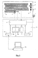
- FIG. 1 For the sake of clarity, only the components of the digital printer according to the invention which are relevant for the present invention are shown in FIG.
- One recognizes a transport device 1 typically realized by means of rollers for substrate (paper) 2 to be printed, a print head 3 equipped with a large number of individual nozzles, a drive symbolized only by a double arrow 4 for adjusting the print head 3 transversely to the feed direction 5 of the paper 2, a spectral measuring head 6 and a digital controller 10.
- the latter comprises a computer-based central control unit 11, a program memory 12, a data memory 13, a PC interface 14 and a user interface 15.
- the controller 10 can, in a manner known per se, inputs from a user accept and eg provide visual or audible information to the user.
- the digital printer or its controller 10 can be supplied with printing or other data (for example profiles) from a connected computer PC.
- the control unit 11 executes the device-specific control programs 12a located in the program memory 12 and controls the print head 3, its drive 4 and the transport device 1 for the paper 2 to be printed in a manner known per se.
- the control programs 12a also contain a color management system known per se. Module which performs a transformation of the print data in the printer color space based on stored in the data memory 13 or supplied with the print data or separately from the connected external PC output profiles, thereby causing the color correct print output.
- the control unit 10 also controls the spectral measuring head 6 and takes over and processes the digital measured values generated by the spectral measuring head.
- a suitable spectral measuring head with the associated electronics in order to process the electrical measuring signals into corresponding digital measured values is, for example, in US Pat EP-A-1041372 described.
- the illustrated digital printer corresponds to the state of the art, as described for example by the document US-A 2002/0080373 is represented.
- the differences according to the invention lie, on the one hand, in the arrangement of the spectral (or color) measuring head 6 and, on the other hand, and above all in new functionalities of the digital printer, which are implemented by special software 12b stored in the program memory 12.
- a computer outputs to a printer a 2-dimensional test chart containing a representative number of colors from the printable color space, typically defined in RGB or CMYK coordinates.
- the test chart is then measured with a colorimeter.
- an automatic xy-scanning color measuring system such as e.g. the Spectrolino / SpectroScan system from Gretag-Macbeth AG.
- color profiles for example ICC profiles
- ICC profiles can also be created for input devices such as cameras or scanners.
- PDF files with built-in profiles are created in prepress.
- the integrated profiles describe how the integrated images and the line type or the text are to be displayed correctly in color.
- the profiles generated for the output device e.g., the digital printer
- Such systems have been realized in a wide variety.
- An example of an application that can calculate printer output profiles according to the ICC standard is the system ProfileMaker from Gretag-Macbeth AG. Because the profiling A printer according to such a method by the large number of colors that has to be measured, is relatively time-consuming and error-prone, it is natural to further automate the color measurement and possibly already directly integrated into the output device.
- a typical embodiment of such a system is, for example, in US-A 2002/0080373 described.
- the motion of the print head which is present anyway in an inkjet printer, is utilized transversely to the paper travel direction in order to measure test charts which are output on the printer for the purpose of color management, directly during printing or with a time delay.
- the first significant disadvantage of this embodiment of the measuring device is that an additional mass must be moved with the print head. This has a negative effect on the printing speed and / or on the system costs.
- the drive motors must be strengthened accordingly.
- the color measurement becomes unreliable due to the high acceleration forces.
- the extra head movements necessary to measure the output after printing also slows down the perceived output speed.
- Another problem is that, in this arrangement, the measuring head, which is located directly next to the print head, is potentially contaminated by paint mist and therefore potentially returns erroneous readings.
- the ink is typically not fully absorbed or dried by the substrate shortly after printing. For this reason, the colorimetric values will change significantly.
- the inventive arrangement of a spectral or colorimetric measuring head for data acquisition described below solves this problem.
- the spectral / colorimetric measuring head 6 at a fixed position (preferably at the edge where the paper 2 is struck in the printer) somewhere in the direction of the paper after the pressure line 21 defined by the position of the print head 3 positioned.
- the measuring head does not necessarily have to be mounted at the height of the print head 3. It is even advantageous to position the measuring head 6 at a certain distance (eg 10 cm) in the direction of travel of the paper measured away from the printing head 3. Since the measuring head 6 can not move in this arrangement, it is now necessary for the calculation of an ICC profile required to position 31 in a row (ie a printed field per printed line 31). These measuring fields are then typically printed on the edge where the paper 2 is struck.
- All measuring fields 31, which are needed to create the profile, are then output in this manner and measured by the measuring head 6 spectrophotometrically or colorimetrically.
- the pressure data required for the output of the measuring fields are part of the software 12b or can also be supplied by the connected PC.
- the corresponding measured values are then a per se known profile calculation module contained in the software 12b located in the program memory 12 transmitted.
- This calculation module generates an output device profile (eg according to the ICC standard) which is stored internally in the data memory 13 of the printer (or possibly also externally in the connected PC) and then later in a manner known per se for color-correct output of images and spot colors in this printer is used.
- profile calculation module can be used with advantage the already mentioned software "Profile Maker" from Gretag-Macbeth AG.
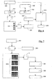
- Fig. 2 summarizes the above operations: 101 denotes the print data (e.g., CMYK) of the metering fields 31 to be output through the print head 3.
- the color measurement values (e.g., Lab) of the measurement fields 31 are symbolized by the box 102.
- the print data 101 and the corresponding color measurement values 102 go into the profile calculation module 103, which calculates the output profile 104 therefrom, which is then stored in the data memory 13.
- the color measurement values 102 of selected or all measurement fields 31 can also be integrated into the output profile 104. This can be done in a manner known per se, e.g. in a so-called private day of the profile.
- the integration of the color measurement values 102 is symbolized by the dotted line 105.
- the color measurement values integrated into the profile 104 are required, for example, in the further development of the invention explained below.
- the colorimeter is designed as a line spectrometer.
- a colorimeter typically has a number of monochromatic or narrowband light sources (e.g., 16 differently colored LEDs) in the illumination, with the light of which a line-shaped area on the paper is sequentially illuminated. The light is brought to the paper via an optical system at a 45 ° angle. At the zero degree angle, the illuminated line to be measured is then imaged onto a line sensor (e.g., CCD sensor) by an optical system.
- a line sensor e.g., CCD sensor
- imaging spectrophotometers Alternative designs of such a line spectrometer are the so-called imaging spectrophotometers.
- the line to be measured in the image is imaged by an optical system on a 2-dimensional detector. In one dimension of the detector, the image is spatially resolved, in the second dimension corresponding to the wavelengths.
- the illumination in such an imaging spectrophotometer is typically performed as white light illumination.
- the printer prints a 2-dimensional measurement chart anywhere on the paper.
- the line spectrophotometer is mounted (transversely to the paper feed direction) exactly at the same place where the chart is printed immovably. Paper feed moves the chart below the line spectrophotometer.
- the measurement data is fed into a profiling module and the corresponding output profiles (for example, according to the ICC standard) are calculated. These ICC profiles are then used in the output of images and spot colors to produce a true color output.
- a built-in colorimeter whether it be a fixed mounted single gauge, a fixed mounted row gauge or a moving single gauge or moving row gauge, can be used to substantially simplify the profiling workflow. Namely, an independent device profile is typically generated for each type of substrate (paper), ink type, etc. This is necessary because the color output on different papers and with different color inks at the same settings of the print parameters will be very different. It would therefore be extremely advantageous if the printer itself could recognize the currently used paper type and thereby select the corresponding Drukkerprofil without user assistance.
- the printer is profiled according to one of the methods described above and an independent device profile (eg ICC profile) 204_1... 204_n is generated for each common system configuration (ink types, paper types, etc.) and stored in the data memory 13 .
- an independent device profile eg ICC profile
- 204_1... 204_n is generated for each common system configuration (ink types, paper types, etc.) and stored in the data memory 13 .
- the color measurement values or the corresponding spectral measured values of a subset of the measuring fields or alternatively of all measuring fields are stored.
- the measurement fields whose color measurement values are stored in the profiles are referred to below as test fields to distinguish them from the measurement fields used for profile formation. These special test fields must always be output the same (ie without using a color profile or without adjusting the amount of ink or the printing speed).
- the storage For example, it can happen in an ICC profile by storing the measurement data in a so-called private tag of the profile.
- additional test fields can be printed out and the measurement data of these additional test fields can be stored in the profile.
- the types of field of view chosen are typically identical to the types of field in an offset print control strip.
- the test fields, whose data are stored, should be measuring fields, which strongly change in color on different papers. Typically, CMYK color fields or solid fields of these colors are used.
- the measured value of the paper white can also be saved ("white field", "paper white”).
- the automatic profile selection then runs according to the following method, which is also contained in or implemented by the software 12b:
- the printer first issues these few test fields 231 identifying a profile on the paper.
- the underlying print data are labeled 201.
- only a white field is output, so nothing printed at all.
- Only the paper white is used as the test field in this minimal case, the characterization consists only of the measurement of the paper.
- the test fields are measured spectrally and / or colorimetrically with the built-in color measuring device 6.
- the spectral or colorimetric differences to the corresponding measured values of the test fields of all profiles 204_1... 204_n stored in the data memory 13 of the printer (or in the connected computer) are calculated in an evaluation module 206.
- the corresponding measured values are read from the private tag of the respective ICC profile and the colorimetric differences to the current measured values of the corresponding measuring fields are generated.
- This can be eg a colorimetric difference ⁇ E according to CIELAB formula).
- the colorimetric differences .DELTA.E are summed over all test fields, the sum then yielding a colorimetric which defines and determines the applicability of an ICC profile to this substrate (in combination with the respectively used color inks).
- the summed colorimetric difference ⁇ E is almost 0 dE CIELAB, whereas the deviation of the summed ⁇ E differences for mismatched profiles reaches relatively high ⁇ E values.
- this profile is automatically displayed as an active profile 204 in the working flow (in the computer or directly in the Printer) and then used later for the full-color print output. If no matching profile is stored, the printer would either issue an error message or automatically switch to profiling mode (block 210) and then generate a matching profile as explained with reference to FIG. This check can optionally be triggered automatically (eg with each printout) or by a user input (user interface 15) on the printer.
- the system is expanded in such a way that after successful checking of the validity of the measured values of the test fields an additional mark 207 in the test strip (totality of the test fields) which indicates the validity of the profile to the user.
- this mark should be printed near the printed test fields so that the user immediately associates the mark with the test result.
- This can be either a graphic mark (check mark or similar) or a bookmark (for example "profile checked on dd.mm.yy").
- print data is communicated to the digital printer RGB or CMYK.
- RGB or CMYK values using the output profile in colorimetric target values for the output Pixel can be converted.
- setpoints can then be compared with the measured color measurements.
- a built-in measuring head usually has an aperture that is much larger than the pixels in the output (eg 1-5 mm diameter).
- the color measuring device 6 measures a suitable test pressure at various predetermined measuring points 331. These measuring points can be distributed across the print like a checkerboard. Any other arrangement of the measuring points is also possible.
- the software 12b in the program memory 12 of the printer determines the colorimetric desired values 303 for the measuring points 331 to be checked by averaging the calculated colorimetric values 302 of the individual pressure points, which are located within the aperture of a measurement, in an averaging stage 304.
- the colorimetric values 302 of the individual pressure points are calculated from the RGB or CMYK values 301 by transformation 305 into the LAB color space using the active output profile 306. These averaged LAB values or setpoint values 303 then serve as reference values for the measurement of the output image the individual measuring points 331.
- the colorimetric differences of the measured values 307 of the printout to the calculated setpoint values 303 of the printout at the individual measuring points 331 are calculated and averaged.
- the calculated average dE error 308 is then the measure of the deviation of the current print output from the desired print output. If this average error 308 is below a predetermined error limit (test 309), the print output is declared valid (OK signaling 310). Otherwise, the user is warned or, optionally, the system is automatically profiled again (profiling 311).
- the built-in color measuring device can be used not only to control subjects printed with the usual standard colors, but also to control spot color areas.
- Named Profiles it can be defined how a print output system can convert spot colors (which are typically denoted by color names such as "Pantone 405C”) into colorimetric coordinates. Such "Named Profiles" can be embedded in PDF files.
- An alternative way to pass the conversion tables of color names in colorimetric values to the printer is to embed an XML-coded conversion table (as defined, for example, in the CxF data exchange format of Gretag-Macbeth AG) in a PDF file and thus with the PDF file to submit the printer or printer driver.
- the special color to be output is transformed into a colorimetric value.
- Each special color in the print output can be assigned a colorimetric reference value 402 in this way. This colorimetric reference value is stored for the measurement. The verification of the special color with the built-in measuring device 6 then takes place according to the following principle:
- the spot color is measured by a built-in colorimetric XY measuring system and compared with the reference value.
- a test field 403 of eg 5 * 5 mm 2 size in the same special color can also be output at the edge of the sheet and measured with a fixed or movably mounted measuring head 6 at this point. If the theoretically determined reference value 402 does not deviate from the current color measurement value 404 or the deviation is smaller than a predefined threshold (eg 1.0 dB CIELAB) (comparison 405), the color is considered correctly printed. If all the colors have been printed correctly, the system signals the user of the correctness of the printed output.
- a predefined threshold eg 1.0 dB CIELAB
- the signaling can be effected, for example, by outputting a specific mark 406 on the printout becomes.
- the signaling can also take place via the user interface 15 of the printer or a message can also be output via the printer / PC interface 14 to the screen of the connected computer PC.
- the profile 502 to be used in conjunction with the color management module 501 is checked in accordance with the procedure described in connection with FIG. 4 (block 503).
- an additional test wedge with predefined test fields 504 is output.
- the typically colorimetrically or spectrally defined test fields 504 of the test wedge are output on the paper with the aid of the (possibly previously verified) ICC profile 502.
- the full tone densities or the colorimetric readings for full tone fields or the tone value increase values or the colorimetric readings for grids are typically known as digital default values 505.
- the built-in measuring device 6 measures the test fields 504 after printing, and from the measured values, the absolute densities, tone value increase values or colorimetric current values 506 of these test fields 504 are calculated (calculation block 507).
- a comparison stage 508 then compares the calculated current values 506 with the digital default values 505.
- a deviation from the default values 505 within the allowable tolerance may again be selectively selected by means of a graphic mark 509 or a corresponding bookmark printed near the test wedge. be signaled to the user.
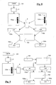
- the following further aspect of the invention shows one way in which the built-in colorimetric measuring head 6 can be used to optimize the ink consumption of a digital printing output system.
- a digital printer must output a different amount of ink to print a color. This is essentially due to the fact that on the one hand the largest possible color space is to be achieved and thus tends to be applied much color and on the other hand from a certain color application (depending on the type of paper) no significant increase in the color space can be achieved more and other disturbing effects occur such as Fault of paper due to moisture. Likewise, it is nonsensical to waste an unnecessary amount of color in order to expand the color space only marginally. With the functionality according to the invention described below in connection with FIG. 7, the digital printer can be further improved. The functionality is also implemented by corresponding routines in the software 12b.
- a special test procedure is started.
- a plurality of measurement wedges 602 for example, 2 grid values each (30%, 70%) and one full tone (100%) are output in the primary colors CMYK, the underlying print data being designated 601.
- the output of these gauges is repeated with different colorant quantity settings 603.
- These gauges are then measured for each base color. For each measuring field of a measuring wedge, the achieved color saturation or the spanned color space 604 is determined thereon. For example, a simple method is to use the "C" coordinates of the LCh color system
- step 605 the relationship between the color spaces 604 achieved and the underlying colorant amount settings 603 is analyzed. If the achieved color space 604 no longer changes significantly as the applied amount of ink (colorant amount adjustment 603) increases, the optimum colorant amount adjustment (color amount) 606 is reached. With this selected amount of ink 606, the prints are then made on this printer or the printer is later profiled in compliance with this amount of ink 606.
- the following aspect of the invention shows how the colorimeter 6 built into the digital printer can be used to solve the so-called wet / dry problem.
- a typical problem that arises in the measurement of colors immediately after printing is the problem of comparing measured values of a measuring field which was measured immediately after printing (in the wet state) with the colorimetric / spectral measured values of a measuring field in total dried condition. Due to the drying process as well as other processes such as e.g. The colorimetric measured values change in the drying process when they are knocked off.
- Various approaches are known in the literature for making the measured values compatible in the wet and dry state. One approach to this is e.g. in the measurement with polarized light (use EP-Zzzzzzz Gretag Case !!!)
- the built-in colorimeter 6 is used to predict the color change of the ink in the drying process and thus from a wet color measurement (which is possible immediately after printing) to the user's measurement of the dry color close without waiting for the drying time.
- This functionality which is likewise implemented by routines in the software 12b, is explained below with reference to FIG.
- the digital printer is profiled in a first step.
- the printer issues a test chart in one of the previously described ways, with the underlying Print data are designated 701.
- the measuring head 6 detects the measuring fields 702a of the test chart immediately after the printing and generates therefrom the corresponding color measurement values 703a.
- a wet device profile 705a is calculated in profiling module 704. This device profile 705a therefore describes the transformation of RGB or CYMK to the CIELAB color space for wet measuring fields for the relevant type of paper.
- the printout is retracted a second time into the printer (this may, for example, happen by loading the printed paper a second time in the paper tray).
- the dry measuring fields in FIG. 8 are designated by 702b.
- the system recognizes that it is an already printed paper.
- the printer can determine which profile has already been assigned to that term when wet. This achieves a clear assignment to a defined paper.
- the printer is now placed in a mode in which the inserted test chart is merely measured.
- the measured values 703b are detected by all the measuring fields 702b of the test chart.
- a dry device profile 705b is then calculated in an analogous manner, which is characteristic for the conversion of CMYK or RGB values into colorimetric values of dry measurement fields.
- This second profile 705b is also assigned internally in the printer to the relevant paper type.
- the profile for the dry readings is used to output the colors correctly. This is justified by the fact that the user has correct colors in the dried Want to have state.
- the profile is used for the transformation of wet measurements. The use of the profile for wet values is particularly useful if measurement fields for the quality assurance or verification of the correct application of the profiles are to be measured directly in the sequence, as shown in various applications above.
- the measured values 703b of the dry sheet are calculated from the wet sheet measurements 703a by a physical model 706.
- the user specifies in which class 707 (coated, uncoated, matt, art print, etc.) the paper belongs.
- class 707 coated, uncoated, matt, art print, etc.
- two main parameters have to be considered.
- the change of the surface effect This can typically be modeled by adding to each reflectance value of each wet sample reading a small reflectance value (typically 1% to 4%).
- a further correction to take account of the impact on the paper it is often advisable to take into account the additional scatter introduced by the paper.
- the corresponding formulas are generally known (see models by Kubelka / Munk and Hoffmann / Schmelzer).
- R dry f R wet ⁇ S + O
- O typically a constant that is the same and characteristic of the surface effect in all wavelengths for all colors
- S is a constant or wavelength-dependent parameter that characterizes the scattering behavior of the paper.
- the values S and O required for the measurement correction depend on the type of paper used and are typical for a paper.
- the printer will therefore in a further step (based on the user preference of the paper type) the corresponding S and O Read values from a paper class database and use the Model 706 to convert all reflectance values to measured values 703b of a dry sheet.
- the profile 705b for the dry arc is again calculated. Thereafter, the procedure is again as in the previous case in which the two profiles 705a and 705b (for wet and dry) are assigned to a paper type and applied as in the previous case.
- the last aspect of the present invention explained below with reference to FIG. 10 shows how the digital printer can be periodically checked for compliance with a measurement tolerance and therefore for compliance with a maximum deviation from a standard.
- a calibration chart 801 with a palette of measuring fields 802 in colors which distribute as possible over the entire color space is printed out for suitable location. (These could be, for example, 12 saturated colors from the color wheel as well as black, gray and paper white.)
- the colorimetric values 803 of these measurement fields 802 are then recorded in a central calibration laboratory using a spectrophotometer 804.
- the calibration chart 801 is provided with a color code 805 for identification.
- the calibration chart 801 is constructed in such a way that white fields are interwoven periodically between the colored measurement fields, which serve to increase the accuracy of the system by means of an intermediate calibration on paper white.
- the printed calibration chart 801 and the associated measurement data 803 are transmitted to the user for checking the colorimetric correctness of his printer.
- the user loads the measurement data 803 onto the printer (via the PC or via a suitable interface on the printer itself). These measurement data 803 represent the reference value.
- the chart 801 is inserted into the paper slot of the printer.
- the printer automatically recognizes by the built-in colorimeter 6 (by detecting the color code 805 on the chart with the colorimeter 6) that this is a calibration chart 801.
- the printed color patches 802 are measured and the color measured values 806 determined thereby are compared with the previously fed reference values 803.
- a step 807 calculates the maximum colorimetric deviations and the mean colorimetric deviation of the colorimetric values 806 of all measurement fields 802 relative to the reference values 803. If the mean deviation and the maximum deviation of any color measurement field 802 are below a predetermined limit, the printer is considered to be calibrated. Compliance or non-compliance with the limits are signaled to the user by e.g. a certificate 808 or a deviation protocol is issued on the printer.
- the accuracy of the system can, as already mentioned, be further increased by performing an intermediate calibration on paper white on the basis of the white fields woven into the calibration chart.
Landscapes
- Physics & Mathematics (AREA)
- Spectroscopy & Molecular Physics (AREA)
- Engineering & Computer Science (AREA)
- Multimedia (AREA)
- Signal Processing (AREA)
- General Physics & Mathematics (AREA)
- Accessory Devices And Overall Control Thereof (AREA)
- Spectrometry And Color Measurement (AREA)
- Color Image Communication Systems (AREA)
Description
Die Erfindung betrifft einen Digitaldrucker gemäss dem Oberbegriff des unabhängigen Anspruchs 1.The invention relates to a digital printer according to the preamble of the
Color Management ist heute ein anerkanntes Verfahren, um auf verschiedensten Einund Ausgabegeräten eine konsistente Farbwiedergabe zu erhalten. Die entsprechenden Algorithmen und Verfahren sind wohl bekannt und entsprechende Produkte sind auf dem Markt (z.B. die Software "Profile Maker" der Firma Gretag-Macbeth AG). Speziell bei der Ausgabe von Referenzdrucken zur Begutachtung durch den Kunden (sog. Proofs) werden an Color Management Systeme höchste Anforderungen gestellt.Today, color management is a recognized way to achieve consistent color reproduction on a wide range of input and output devices. The corresponding algorithms and methods are well known and corresponding products are on the market (e.g., the "Profile Maker" software from Gretag-Macbeth AG). Especially when issuing reference prints for customer evaluation (so-called proofs), the highest demands are placed on color management systems.
Dennoch weisen die heute verwendeten Verfahren und Abläufe in der konkreten Implementation eines Color Management Arbeitsflusses erhebliche Schwachstellen auf. Die Anwendung des Color Management ist komplex. Anwender werden meist nur mangelhaft unterstützt. Die potentiellen Fehlerquellen sind enorm. Die korrekte Anwendung der Arbeitsflüsse wird / kann heute nur visuell beurteilt werden. Um die Abläufe zu vereinfachen, müssen zukünftige Color Management Systeme intelligenter werden. Insbesondere müssen Digitaldrucker selbstkalibrierend werden, um den Benutzer zu entlasten. Es ist dazu notwendig, Farbmessgeräte direkt in den Digitaldrucker zu integrieren. In letzter Zeit sind von verschiedenen Firmen Patentanmeldungen hinterlegt worden (vg. z. Bsp.
Ein wesentlicher Hinderungsgrund beim breiten Einsatz von Color Management Lösungen liegt in der Komplexität und der dadurch induzierten Fehleranfälligkeit der Abläufe. Obwohl die in den genannten Patentanmeldungen beschriebenen Systeme zur Vereinfachung / Optimierung des Color Management Arbeitsflusses beitragen, sind durch diese für die Reduktion der Systemkomplexität wichtige Aspekte in keiner Art und Weise abgedeckt. Insbesondere decken die in den genannten Patentanmeldungen beschriebenen Systeme den Aspekt der Profilauswahl, Profilverifikation, der effizienten Abhandlung des Nass-trocken-Problems, der Optimierung der verwendeten Farbmenge sowie im allgemeinen der Kontrolle des Ausgaberesultates und den Aspekt der Rückverfolgbarkeit in keiner Art und Weise ab.A major obstacle to the widespread use of color management solutions lies in the complexity and the resulting error-prone nature of the processes. Although the systems described in the cited patent applications contribute to the simplification / optimization of the color management workflow, these aspects, which are important for the reduction of system complexity, are in no way covered. In particular, those in the cited patent applications cover describe the aspect of profile selection, profile verification, efficient handling of the wet-dry problem, optimization of the amount of ink used, and generally control of the output and aspect of traceability in no way.
Allgemeinstes Ziel dieser Erfindung ist es daher einen Digitaldrucker mit einem eingebauten Farbmessgerät und integriertem Farbmanagement dahingehend zu verbessern, dass die folgend beschriebenen Aspekte eines Color Management unterstützten Arbeitsflusses in einer für den Benutzer optimalen Art und Weise realisiert werden.The most general object of this invention, therefore, is to improve a digital printer having a built-in colorimeter and integrated color management so as to realize the following described aspects of a color management assisted workflow in a manner optimal to the user.
Diese der Erfindung zugrundeliegende Aufgabe wird durch den durch die Merkmale des unabhängigen Anspruchs 1 gekennzeichneten erfindungsgemässen Digitaldrucker gelöst.This problem underlying the invention is solved by the inventive digital printer characterized by the features of the
Vorteilhafte Ausgestaltungen und Weiterbildungen des erfindungsgemässen Digitaldruckers sind Gegenstand der abhängigen Ansprüche.Advantageous embodiments and further developments of the inventive digital printer are the subject of the dependent claims.
Konkreter beschäftigt sich die Erfindung gemäss einem ersten Hauptaspekt mit der Systemoptimierung und der Verbesserung des Störanfälligkeitsverhaltens bei der Messwerterfassung.More specifically, the invention is concerned, according to a first main aspect, with the system optimization and the improvement of the susceptibility to interference during measured value acquisition.
Das Erfassen der benötigten Daten soll so einfach wie möglich sein. Der klassische Ansatz für das Color Management von Remissionsmessvorlagen besteht darin, dass ein zweidimensionales Testchart durch ein xy-Messsystem ausgemessen wird. Dieser häufig gebrauchte Ansatz wird in einem Inkjet Drucksystem typischerweise (wie z.B. in
Gemäss dem genannten ersten Hauptaspekt der vorliegenden Erfindung werden sowohl die Systemkosten optimiert als auch das Verhalten betreffend Störanfälligkeit des Verfahrens wesentlich verbessert, indem die zur Messung und Profilierung benötigen Testfelder in einer Reihe an einer festen Position des Testchartes, vorzugsweise am Rand des Papiers, ausgegeben und ausgemessen werden.According to the said first main aspect of the present invention, both the system costs are optimized and the behavior susceptibility of the method significantly improved by the need for measurement and profiling test fields in a row at a fixed position of the test chart, preferably at the edge of the paper, issued and be measured.
Eine weitere konkretere Aufgabe der vorliegenden Erfindung betrifft die Verbesserung der Handhabung von Profilen.Another more specific object of the present invention is to improve the handling of profiles.
Der allseits bekannte Ansatz in der Geräteprofilierung ist heute derart, dass für eine bestimmte Kombination von Papier, Farben, UCR Einstellungen u.s.w. ein sogenanntes Ausgabeprofil berechnet wird. Abhängig von den gewählten Druckbedingungen bei der Ausgabe (z.B. dem gewählten Papier) muss dann typischerweise in den Einstellungen des Druckertreibers ein bestimmtes Profil vorgewählt werden, um die korrekte Ausgabe zu erhalten. Diese Einstellung ist fehleranfällig. Eine falsche Einstellung führt aber zu einem falschen Ausgaberesultat.The well-known approach in device profiling is today such that for a certain combination of paper, colors, UCR settings and so on. a so-called output profile is calculated. Depending on the printing conditions selected for the output (e.g., the selected paper), then, in the printer driver's settings, a particular profile typically must be preselected to obtain the correct output. This setting is error prone. An incorrect setting leads to a wrong output result.
Diese Schwierigkeit wird gemäss einem weiteren Hauptaspekt der vorliegenden Erfindung dadurch gelöst, dass die Auswahl des korrekten Farbprofils durch den Digitaldrucker selbst automatisch vorgenommen werden kann. Gemäss einem zusätzlichen Aspekt werden durch die vorgenommenen Messungen weitere Parameter wie z.B. das Wegschlagverhalten des Bedruckstoffes klassifiziert und dieses Wissen dazu benutzt, entsprechende Korrekturen / Klassifikationen vorzunehmen, die das Druckresultat zu optimieren erlauben.This difficulty is solved according to a further main aspect of the present invention in that the selection of the correct color profile by the digital printer itself can be made automatically. According to an additional aspect, the measurements made make further parameters such as e.g. classifies the impact behavior of the substrate and uses this knowledge to make appropriate corrections / classifications that allow to optimize the print result.
Eine weitere konkretere Aufgabe der Erfindung betrifft die Verifikation der Profilauswahl.Another more specific object of the invention relates to the verification of the profile selection.
Auf Grund des grossen Farbfehlers bei falscher Profilwahl, auf welche Art immer eine Ausgabeprofil eines Digitaldruckers bestimmt wird (automatisch durch den Drukker selbst oder durch manuelle Anwahl), muss in einem benutzerfreundlichen System sichergestellt werden, dass das richtige Profil gewählt worden ist, und dass das Profil immer noch gültig ist und nicht etwa durch ein Wegdriften des Druckergebnisses ungültig bzw. unbrauchbar geworden ist. Ein weiterer Hauptaspekt der vorliegenden Erfindung zeigt auf, wie die Gültigkeit des Ausgabeprofils auf Grund von Messungen eines Testkeiles und / oder des ausgegebenen Drucks verifiziert werden kann. In einem weiteren Aspekt wird ferner aufgezeigt, wie die Gültigkeit der Profilierung dem Anwender auf eine intuitive und benutzerfreundliche Art und Weise durch Ausdruck zusätzlicher Information angezeigt werden kann.Due to the large color error in case of wrong profile selection, in which way an output profile of a digital printer is always determined (automatically by the printer or by manual selection), it must be ensured in a user-friendly system that the correct profile has been selected and that Profile is still valid and has not become invalid or unusable, for example, as a result of drifting away of the print result. Another major aspect of the present invention demonstrates how the validity of the output profile based on measurements a test wedge and / or the issued pressure can be verified. In a further aspect, it is further shown how the validity of the profiling can be displayed to the user in an intuitive and user-friendly manner by printing additional information.
Eine weitere Schwierigkeit, die bei der Anwendung von in Digitaldruckern eingebauten Color Management Funktionen und der dazu benötigten Messtechnik entsteht, liegt in der Problematik begründet, dass bei den meisten Druckverfahren (Inkjet, Offset, Flexo ..) nasse Farbe auf ein trockenes Papier aufgebracht wird. Durch die Trocknungsprozesse verändern sich die Farben nach dem Druck. Ein Messsystem, das die Farben zeitlich nahe nach dem Druck misst, wird deshalb nie die gleichen Messwerte für dieselbe Farbe liefern, nachdem die Farbe getrocknet ist. Für die Beurteilung des endgültigen Druckergebnisses ist aber der vollständig getrocknete Druck massgebend.Another difficulty that arises when using color management functions built into digital printers and the measurement technology required for them lies in the problem that in most printing processes (inkjet, offset, flexo ..) wet ink is applied to a dry paper , Due to the drying processes, the colors change after printing. Therefore, a measurement system that measures the colors near time after printing will never provide the same readings for the same color after the ink has dried. For the assessment of the final printing result, however, the completely dried pressure is decisive.
Ein weitere konkretere Aufgabe der vorliegenden Erfindung besteht daher darin, mit Hilfe von mathematischen und/oder messtechnischen Mitteln die intern gemessenen Werte mit den extern im trockenen Zustand gemessenen Werten zu korrelieren und diese Korrelation in einen ICC kompatiblen Arbeitsfluss nahtlos und für den Benutzer optimal zu integrieren. In einem weiteren Teilaspekt wird zudem aufgezeigt, wie durch zweimaliges Messen im zeitlichen Versatz derselben Probe mit dem im Digitaldrucker integrierten Farbmesssystem die Trocknungsaspekte charakterisiert und kompensiert werden können.A further more specific object of the present invention is therefore to correlate the internally measured values with the values measured externally in the dry state by means of mathematical and / or metrological means and to integrate this correlation into an ICC-compatible workflow seamlessly and optimally for the user , In a further sub-aspect, it is also shown how the drying aspects can be characterized and compensated by measuring the same sample twice in the same sample interval with the color measuring system integrated in the digital printer.
Beim Ausdruck sind neben den vierfarbigen (CMYK) Bildern mehr und mehr auch die korrekte Ausgabe von Sonderfarben (Spot Colors) wichtig. Eine weitere konkretere Aufgabe der vorliegenden Erfindung besteht darin, das eingebaute Messsystem zur immanent wichtigen Kontrolle von Spotfarben auf dem Digitaldruck verwenden zu können. Dabei wird insbesondere aufgezeigt, wie dynamisch generierte Messstreifen zu diesem Zweck hervorragend verwendet werden können und/oder wie alternativ die Farben direkt im Nutzen gemessen werden können.When printing, in addition to the four-color (CMYK) images more and more, the correct output of spot colors are important. Another more concrete object of the present invention is to be able to use the built-in measuring system for the inherently important control of spot colors on digital printing. In particular, it will be shown how dynamically generated measuring strips can be excellently used for this purpose and / or how alternatively the colors can be measured directly in terms of their usefulness.
Ein weiteres Hindernis in der korrekten Anwendung heutiger Digitaldrucksysteme besteht darin, dass die Papierart aus einer bestimmten Klasse vorgewählt werden muss. Aus dieser Papierartklasse leitet z.B. ein Inkjet-Drucksystem die auf das Papier aufgebrachte Farbmenge ab. Sobald neue unbekannte Papiere zum Einsatz kommen, wird sich das Druckresultat auf Grund der nicht bekannten Menge der aufzubringenden Farbe verschlechtern.Another obstacle in the correct use of today's digital printing systems is that the paper must be selected from a certain class. From this paper type class derives e.g. an inkjet printing system removes the amount of ink applied to the paper. As soon as new unknown papers are used, the print result will worsen due to the unknown amount of ink to be applied.
Gemäss einem weiteren wichtigen Aspekt der Erfindung wird dieses Problem mit einem Kalibrationsalgorithmus gelöst, der auf den eingebauten Sensor zurückgreift und der es ermöglicht, mit dem gezeigten Verfahren die optimale auf den Druck aufzubringende Farbmenge zu bestimmen, um einerseits einen möglichst grossen Farbraum zu erreichen und andererseits nur die sinnvoll notwendige Farbmenge auf den Druck aufzubringen.According to a further important aspect of the invention, this problem is solved by a calibration algorithm, which uses the built-in sensor and makes it possible to determine with the method shown, the optimum applied to the pressure amount of ink, on the one hand to achieve the largest possible color space and on the other hand apply only the sensible amount of ink to the print.
Es ist weiterhin wichtig, dass solche intelligente Druckersysteme einfach auf ihre korrekte Funktion überprüft werden können. Ein weiterer Aspekt der vorliegenden Erfindung zeigt eine Möglichkeit auf, wie die korrekte Funktion eines derartigen farbechten Druckers periodisch überprüft werden kann.It is also important that such intelligent printer systems can be easily checked for their correct function. Another aspect of the present invention shows one way in which the correct operation of such a color fast printer can be periodically checked.
Im folgenden wird die Erfindung anhand der Zeichnung näher erläutert. Es zeigen:
- Fig. 1
- ein Prinzip-Blockschema eines Ausführungsbeispiels des erfindungsgemässen Digitaldruckers,
- Fig. 2
- ein Blockschema der Profilierungsfunktion des Digitaldruckers,
- Fig. 3
- ein Blockschema einer automatischen Profilauswahlfunktion,
- Fig. 4
- ein Blockschema einer automatischen Profilverifikationsfunktion,
- Fig. 5
- ein Blockschema einer Verifikationsfunktion für Sonderfarben,
- Fig. 6
- ein Blockschema einer Prüfungsfunktion für Standardbedingungen,
- Fig. 7
- ein Blockschema einer Eintestfunktion für die optimale Farbmenge,
- Fig. 8
- ein Blockschema einer Funktion zur Berechnung von Profilen für nasse und getrocknete Farben,
- Fig. 9
- ein Blockschema einer alternativen Funktion zur Berechnung von Profilen für nasse und getrocknete Farben und
- Fig. 10
- ein Blockschema einer Kalibrierungsfunktion.
- Fig. 1
- 1 is a block diagram of an embodiment of the digital printer according to the invention,
- Fig. 2
- a block diagram of the profiling function of the digital printer,
- Fig. 3
- a block diagram of an automatic profile selection function,
- Fig. 4
- a block diagram of an automatic profile verification function,
- Fig. 5
- a block diagram of a verification function for special colors,
- Fig. 6
- a block diagram of a test function for standard conditions,
- Fig. 7
- a block diagram of a test function for the optimum amount of ink,
- Fig. 8
- a block diagram of a function for calculating profiles for wet and dried colors,
- Fig. 9
- a block diagram of an alternative function for calculating profiles for wet and dried colors and
- Fig. 10
- a block diagram of a calibration function.
In der Fig. 1 sind der Übersichtlichkeit halber nur die für die vorliegende Erfindung relevanten Komponenten des erfindungsgemässen Digitaldruckers dargestellt. Man erkennt eine typischerweise durch Walzen realisierte Transportvorrichtung 1 für zu bedruckendes Substrat (Papier) 2, einen mit einer grösseren Anzahl von Einzeldüsen ausgestatteten Druckkopf 3, einen nur durch einen Doppelpfeil 4 symbolisierten Antrieb zur Verstellung des Druckkopfs 3 quer zur Vorschubrichtung 5 des Papiers 2, einen Spektralmesskopf 6 und eine digitale Steuerung 10. Letztere umfasst eine rechnerbasierte zentrale Steuereinheit 11, einen Programmspeicher 12, einen Datenspeicher 13, eine PC-Schnittstelle 14 und eine Benutzerschnittstelle 15. Über letztere kann die Steuerung 10 in an sich bekannter Weise Eingaben von einem Benutzer entgegennehmen und z.B. optische oder akustische Informationen an den Benutzer ausgeben. Über die PC-Schnittstelle 14 können dem Digitaldrucker bzw. seiner Steuerung 10 Druck- oder andere Daten (z.B. Profile) von einem angeschlossenen Rechner PC zugeführt werden.For the sake of clarity, only the components of the digital printer according to the invention which are relevant for the present invention are shown in FIG. One recognizes a
Die Steuereinheit 11 führt die im Programmspeicher 12 befindlichen gerätetypische Steuerungsprogramme 12a aus und steuert dabei in an sich bekannter Weise den Druckkopf 3, dessen Antrieb 4 und die Transportvorrichtung 1 für das zu bedruckende Papier 2. Die Steuerungsprogramme 12a enthalten auch ein an sich bekanntes Farbmanagement-Modul, welches anhand von im Datenspeicher 13 abgelegten oder mit den Druckdaten oder separat vom angeschlossenen externen PC zugeführten Ausgabeprofilen eine Transformation der Druckdaten in den Druckerfarbraum durchführt und dadurch die farbrichtige Druckausgabe bewirkt.The
Die Steuereinheit 10 steuert ferner auch den Spektralmesskopf 6 und übernimmt und verarbeitet die vom Spektralmesskopf erzeugten digitalen Messwerte.The
Ein geeigneter spektraler Messkopf mit der zugehörigen Elektronik, um die elektrischen Messsignale in entsprechende digitale Messwerte zu verarbeiten, ist z.B. in der
In dieser Allgemeinheit entspricht der dargestellte Digitaldrucker dem Stand der Technik, wie er z.B. durch das Dokument
Color Management Systeme zur Kontrolle von Druckern sind heute typischerweise in der folgenden Art realisiert. Ein Computer gibt an einen Drucker ein 2-dimensionales Testchart aus, das eine representative Anzahl von Farben aus dem druckbaren Farbraum enthält, die typischerweise in RGB oder CMYK Koordinaten definiert sind. Das Testchart wird danach mit einem Farbmessgerät ausgemessen. Dabei wird aus Komfortgründen oft ein automatisch xy-scannendes Farbmesssystem wie z.B. das Spectrolino / SpectroScan System der Firma Gretag-Macbeth AG verwendet. Aus den Beziehungen der bekannten RGB bzw. CMYK Werte und den gemessenen farbmetrischen Werten dieses Testcharts werden darauf durch mathematische Umformungen und Interpolationen sogenannte Farbprofile (z.B. ICC Profile) errechnet. Analog können für Eingabegeräte wie Kameras oder Scanner ebenfalls ICC Profile erstellt werden. In einem typischen Arbeitsfluss werden in der Druckvorstufe PDF Dateien mit integrierten Profilen erstellt. Die integrierten Profile beschreiben, wie die integrierten Bilder und die Linenart bzw. der Text korrekt farblich auszugeben sind. Die für das Ausgabegerät (z.B. den Digitaldrucker) erzeugten Profile können dann dazu benutzt werden, auf dem Drucker auszugebende Bilder oder Sonderfarben farblich korrekt darzustellen.Today, color management systems for controlling printers are typically implemented in the following manner. A computer outputs to a printer a 2-dimensional test chart containing a representative number of colors from the printable color space, typically defined in RGB or CMYK coordinates. The test chart is then measured with a colorimeter. For reasons of comfort, an automatic xy-scanning color measuring system, such as e.g. the Spectrolino / SpectroScan system from Gretag-Macbeth AG. From the relationships of the known RGB or CMYK values and the measured colorimetric values of this test chart, so-called color profiles (for example ICC profiles) are calculated thereon by mathematical transformations and interpolations. Similarly, ICC profiles can also be created for input devices such as cameras or scanners. In a typical workflow, PDF files with built-in profiles are created in prepress. The integrated profiles describe how the integrated images and the line type or the text are to be displayed correctly in color. The profiles generated for the output device (e.g., the digital printer) may then be used to color accurately display images or spot colors to be output on the printer.
Derartige Systeme sind in einer grossen Vielfalt realisiert worden. Ein Beispiel für eine Anwendung, die Druckerausgabeprofile nach dem ICC Standard berechnen kann, ist das System ProfileMaker der Firma Gretag-Macbeth AG. Da die Profilierung eines Druckers nach einem derartigen Verfahren durch die grosse Anzahl von Farben, die ausgemessen werden muss, relativ zeitaufwändig und fehlerbehaftet ist, liegt es nahe, die Farbmessung weiter zu automatisieren und möglichst bereits in das Ausgabegerät direkt zu integrieren. Eine typische Ausgestaltung eines derartigen Systems ist zum Beispiel in
In der erfindungsgemässen Anordnung nach Fig. 1 wird der spektrale / farbmetrische Messkopf 6 an einer festen Position (vorzugsweise am Rand, an dem das Papier 2 im Drucker angeschlagen wird) irgendwo in Laufrichtung des Papiers nach der durch die Position des Druckkopfs 3 definierten Druckzeile 21 positioniert. Der Messkopf muss dabei nicht unbedingt auf Höhe des Druckkopfes 3 montiert werden. Es ist sogar vorteilhaft, den Messkopf 6 in einem gewissen Abstand (z.B. 10 cm) in Papierlaufrichtung gemessen vom Druckkopf 3 entfernt zu positionieren. Da sich der Messkopf 6 in dieser Anordnung nicht bewegen kann, ist es nun notwendig, die für die Berechnung eines ICC Profiles benötigten Messfelder 31 in einer Reihe (d.h. pro gedruckter Zeile ein Messfeld 31) zu positionieren. Diese Messfelder werden dann typischerweise an dem Rand, an dem das Papier 2 angeschlagen wird, ausgedruckt. Alle Messfelder 31, die zur Erstellung des Profiles benötigt werden, werden dann in dieser Weise ausgegeben und durch den Messkopf 6 spektralfotometrisch oder farbmetrisch ausgemessen. (Die für die Ausgabe der Messfelder erforderlichen Druckdaten sind Bestandteil der Software 12b oder können auch vom angeschlossenen PC zugeführt werden.) Nach dem Ausmessen aller Messfelder 31 werden die entsprechenden Messwerte dann einem in der im Programmspeicher 12 befindlichen Software 12b enthaltenen, an sich bekannten Profilberechnungsmodul übermittelt. Dieses Rechenmodul erzeugt ein Ausgabegeräteprofil (z.B. nach dem ICC Standard), welches intern im Datenspeicher 13 des Druckers (oder ggf. auch extern im angeschlossenen PC) gespeichert wird und dann später in an sich bekannter Weise zur farbrichtigen Ausgabe von Bildern und Sonderfarben in diesem Drucker verwendet wird. Als Profilberechnungsmodul kann mit Vorteil die schon erwähnte Software "Profile Maker" der Firma Gretag-Macbeth AG eingesetzt werden.1, the spectral /
Die Fig. 2 fasst die vorstehenden Abläufe zusammen: Mit 101 sind die Druckdaten (z.B. CMYK) der über den Druckkopf 3 auszugebenden Messfelder 31 bezeichnet. Die Farbmesswerte (z.B. Lab) der Messfelder 31 sind durch den Kasten 102 symbolisiert. Die Druckdaten 101 und die entsprechenden Farbmesswerte 102 gehen in das Profilberechnungsmodul 103, welches daraus das Ausgabeprofil 104 berechnet, das dann im Datenspeicher 13 abgespeichert wird. In das Ausgabeprofil 104 können bei Bedarf auch die Farbmesswerte 102 ausgewählter oder aller Messfelder 31 integriert werden. Dies kann in an sich bekannter Weise z.B. in einem sog. Private Tag des Profils erfolgen. Die Integration der Farbmesswerte 102 ist durch den strichlierten Pfeil 105 symbolisiert. Die in das Profil 104 integrierten Farbmesswerte werden zum Beispiel in der weiter unten erläuterten Weiterbildung der Erfindung benötigt.Fig. 2 summarizes the above operations: 101 denotes the print data (e.g., CMYK) of the metering fields 31 to be output through the
In einigen Anwendungen, z.B. begründet durch den Wunsch Papier zu sparen, ist es wünschenswert, auf einer Zeile mehrere Messfelder auszudrucken. Für diesen Fall ist der nachstehend erläuterte erfindungsgemässe alternative Systemaufbau geeignet, welcher die Vorteile eines statisch montierten Messkopfes mit den Vorteilen einer zweidimensionalen Messung kombiniert.In some applications, for example, due to the desire to save paper, it is desirable to print several fields on one line. In this case, the alternative system structure according to the invention explained below is suitable, which combines the advantages of a statically mounted measuring head with the advantages of a two-dimensional measurement.
Gemäss diesem Ausführungsbeispiel der Erfindung ist das Farbmessgerät als Zeilenspektrometer ausgebildet. Ein derartiges Farbmessgerät besitzt typischerweise in der Beleuchtung eine Anzahl von monochromatischen bzw. schmalbandigen Lichtquellen (z.B. 16 verschiedenfarbige LED's), mit deren Licht eine zeilenförmige Fläche auf dem Papier sequentiell beleuchtet wird. Das Licht wird dabei über ein optisches System in einem 45° Winkel auf das Papier gebracht. Im Nullgradwinkel wird dann die beleuchtete zu messende Zeile durch ein optisches System auf einen Zeilensensor (z.B. CCD Sensor) abgebildet. Indem nacheinander das Papier mit 16 verschiedenen Farben beleuchtet wird und die entsprechenden Signale auf dem Sensor detektiert und ausgewertet werden, steht durch dieses Messprinzip für jeden Punkt der Zeile ein (diskretes) Spektrum zur Verfügung.According to this embodiment of the invention, the colorimeter is designed as a line spectrometer. Such a colorimeter typically has a number of monochromatic or narrowband light sources (e.g., 16 differently colored LEDs) in the illumination, with the light of which a line-shaped area on the paper is sequentially illuminated. The light is brought to the paper via an optical system at a 45 ° angle. At the zero degree angle, the illuminated line to be measured is then imaged onto a line sensor (e.g., CCD sensor) by an optical system. By successively illuminating the paper with 16 different colors and detecting and evaluating the corresponding signals on the sensor, this measuring principle provides a (discrete) spectrum for each point of the line.
Alternative Bauformen eines solchen Zeilenspektrometers sind die sogenannten Imaging Spektralfotometer. Dabei wird die zu messende Zeile im Bild durch ein optisches System auf einen 2-dimensionalen Detektor abgebildet. In der einen Dimension des Detektors wird das Bild dabei örtlich (spatial) aufgelöst, in der zweiten Dimension entsprechend den Wellenlängen. Die Beleuchtung in einem derartigen Imaging Spektralfotometer wird typischerweise als Weisslichtbeleuchtung ausgeführt.Alternative designs of such a line spectrometer are the so-called imaging spectrophotometers. The line to be measured in the image is imaged by an optical system on a 2-dimensional detector. In one dimension of the detector, the image is spatially resolved, in the second dimension corresponding to the wavelengths. The illumination in such an imaging spectrophotometer is typically performed as white light illumination.
Sowohl mit mehreren monochromatischen Lichtquellen ausgerüstete Zeilenspektrometer als auch Imaging Spektralfotometer sind wohlbekannt und bedürfen deshalb für den Fachmann keiner näheren Erläuterung.Both line spectrometers equipped with a plurality of monochromatic light sources and imaging spectrophotometers are well known and therefore require no further explanation by the person skilled in the art.
Unabhängig von der konkreten Bauform des verwendeten Zeilenspektrometers wird programmtechnisch durch die Software 12b die folgende Funktionalität erzeugt:Regardless of the specific design of the line spectrometer used, the following functionality is generated programmatically by the
Der Drucker druckt ein 2-dimensionales Messchart an irgend einer Stelle des Papiers aus. Das Zeilenspektralfotometer ist dabei (quer zur Papiervorschubrichtung) exakt an derselben Stelle, an welcher das Chart ausgedruckt wird, unbeweglich montiert. Durch den Papiervorschub wird das Chart unter dem Zeilenspektralfotometer bewegt.The printer prints a 2-dimensional measurement chart anywhere on the paper. The line spectrophotometer is mounted (transversely to the paper feed direction) exactly at the same place where the chart is printed immovably. Paper feed moves the chart below the line spectrophotometer.
Dadurch ist es möglich, die gesamten farbmetrischen Messdaten des 2-dimensionalen Charts messtechnisch zu erfassen. Sobald die Messdaten erfasst sind, werden die Messdaten in ein Profilierungsmodul eingespeist und die entsprechenden Ausgabeprofile (z.B. nach dem ICC Standard) berechnet. Diese ICC Profile werden dann bei der Ausgabe der Bilder und Sonderfarben angewendet, um eine farbrichtige Ausgabe zu erzeugen.This makes it possible to metrologically capture the entire colorimetric measurement data of the 2-dimensional chart. Once the measurement data is collected, the measurement data is fed into a profiling module and the corresponding output profiles (for example, according to the ICC standard) are calculated. These ICC profiles are then used in the output of images and spot colors to produce a true color output.
In einem weiteren Aspekt dieser Erfindung wird aufgezeigt, wie ein eingebautes Farbmessgerät, unabhängig davon, ob es sich um einen fix montierten Einzelmesskopf, einen fix montierten Zeilenmesskopf oder einen bewegten Einzelmesskopf oder bewegten Zeilenmesskopf handelt, dazu verwendet werden kann, den Profilierungsarbeitsfluss wesentlich zu vereinfachen. Typischerweise wird nämlich für jeden Substrattyp (Papier), Tintentyp etc. ein unabhängiges Geräteprofil erzeugt. Dies ist notwendig, weil die Farbausgabe auf unterschiedlichen Papieren und mit unterschiedlichen Farbtinten bei den selben Einstellungen der Druckparameter sehr unterschiedlich ausfällt. Es wäre daher äussert vorteilhaft, wenn der Drucker selber den aktuell verwendeten Papiertyp selbst erkennen könnte und dadurch das entsprechende Drukkerprofil ohne Benutzerhilfe anwählen würde.In a further aspect of this invention, it is demonstrated how a built-in colorimeter, whether it be a fixed mounted single gauge, a fixed mounted row gauge or a moving single gauge or moving row gauge, can be used to substantially simplify the profiling workflow. Namely, an independent device profile is typically generated for each type of substrate (paper), ink type, etc. This is necessary because the color output on different papers and with different color inks at the same settings of the print parameters will be very different. It would therefore be extremely advantageous if the printer itself could recognize the currently used paper type and thereby select the corresponding Drukkerprofil without user assistance.
Um diesen vorteilhaften Aspekt der Erfindung zu realisieren, wird folgendes Vorgehen durch die Software 12b programmtechnisch implementiert (Fig. 3):In order to realize this advantageous aspect of the invention, the following procedure is implemented programmatically by the
In einem ersten Schritt wird der Drucker nach einem der vorgängig beschriebenen Verfahren profiliert und dabei für jede gängige Systemkonfiguration (Tinten-Typen, Papier-Typen etc.) ein unabhängiges Geräteprofil (z.B. ICC Profil) 204_1 ... 204_n erzeugt und im Datenspeicher 13 abgelegt. In jedem Profil werden zusätzlich zu den eigentlichen Profilierungsdaten die Farbmesswerte (oder die entsprechenden Spektralmesswerte) einer Teilmenge der Messfelder oder alternativ aller Messfelder abgespeichert. Die Messfelder, deren Farbmesswerte in den Profilen gespeichert werden, werden im folgenden zur Unterscheidung von den Messfeldern, die zur Profilbildung herangezogen werden, als Testfelder bezeichnet. Diese speziellen Testfelder müssen dabei immer gleich (d.h. ohne Anwendung eines Farbprofiles oder ohne Anpassung der Farbmenge oder der Druckgeschwindigkeit) ausgegeben werden. Die Speicherung kann z.B. in einem ICC Profil dadurch passieren, dass die Messdaten in einem sogenannten Private Tag des Profils gespeichert werden. Alternativ können auch zusätzliche Testfelder ausgedruckt werden und die Messdaten dieser zusätzlichen Testfelder im Profil mitgespeichert werden. Die Messfeldtypen, die hierzu gewählt werden, sind typischerweise identisch zu den Messfeldtypen in einem Offsetdruck-Kontrollstreifen. Die Testfelder, deren Daten abgespeichert werden, sollten Messfelder sein, die sich auf unterschiedlichen Papieren farblich stark verändern. Typischerweise werden dazu Rasterfelder der Farben CMYK oder Volltonfelder dieser Farben verwendet. Zusätzlich kann z.B. noch der Messwert des Papierweiss mitgespeichert werden ("Weissfeld", "Papierweiss"). Durch die Abspeicherung dieser typischen Messwerte von ausgesuchten Messfeldern (Testfeldern) entsteht quasi ein Fingerabdruck des Verhaltens des Druckers und der Farben auf einem typischen Papier.In a first step, the printer is profiled according to one of the methods described above and an independent device profile (eg ICC profile) 204_1... 204_n is generated for each common system configuration (ink types, paper types, etc.) and stored in the
Die automatische Profilwahl läuft dann nach folgendem Verfahren ab, das ebenfalls in der Software 12b enthalten bzw. durch diese implementiert ist:The automatic profile selection then runs according to the following method, which is also contained in or implemented by the
Der Drucker gibt zuerst diese wenigen Testfelder 231, die ein Profil identifizieren, auf dem Papier aus. Die zugrundeliegenden Druckdaten sind mit 201 bezeichnet. Im Minimalfall wird nur ein Weissfeld ausgegeben, also überhaupt nichts gedruckt. Als Testfeld wird in diesem Minimalfall also nur das Papierweiss verwendet, die Charakterisierung besteht nur aus der Messung des Papiers. Danach werden die Testfelder mit dem eingebauten Farbmessgerät 6 spektral und/oder farbmetrisch ausgemessen. Danach werden in einem Evaluationsmodul 206 die spektralen bzw. farbmetrischen Differenzen zu den entsprechenden Messwerten der Testfelder aller im Datenspeicher 13 des Druckers (oder im angeschlossenen Rechner) gespeicherten Profile 204_1 ... 204_n berechnet. Dazu werden die entsprechenden Messwerte aus dem Private Tag des jeweiligen ICC Profils ausgelesen und die farbmetrischen Differenzen zu den aktuellen Messwerten der entsprechenden Messfelder erzeugt. (Dies kann z.B. eine farbmetrische Differenz ΔE gemäss CIELAB Formel sein). Die farbmetrischen Differenzen ΔE werden über alle Testfelder aufsummiert, wobei die Summe sodann ein Farbmass ergibt, das die Anwendbarkeit eines ICC Profils auf dieses Substrat (in Kombination mit den jeweils eingesetzten Farbtinten) definiert und bestimmt. Im Idealfall ist die aufsummierte farbmetrische Differenz ΔE im Falle des passenden Profils nahezu 0 dE CIELAB, wohingegen die Abweichung der aufsummierten ΔE Differenzen bei nicht passenden Profilen relativ hohe ΔE Werte erreicht. Sollte beim Ausdruck der Messfelder eines der im Drucker oder Computer gespeicherten Profile 204_1 ... 204_n (durch eine hinreichend kleine aufsummierte farbmetrische Differenz ΔE) als passend erkannt worden sein, wird dieses Profil automatisch als aktives Profil 204 im Arbeitsfluss (im Computer oder direkt im Drucker) gesetzt und dann später für die farbrichtige Druckausgabe verwendet. Sollte kein passendes Profil gespeichert sein, würde der Drucker entweder eine Fehlermeldung ausgeben oder automatisch in den Profilierungsmodus (Block 210) wechseln und dann wie anhand der Fig. 2 erläutert ein passendes Profil erzeugen. Diese Ueberprüfung kann wahlweise automatisch (z.B. bei jedem Ausdruck) oder durch eine Benutzereingabe (Benutzerschnittstelle 15) am Drucker ausgelöst werden.The printer first issues these
Um dem Anwender eine Rückmeldung zu geben, ob das Profil geprüft worden und passend ist, wird gemäss einem weiteren Teilaspekt der Erfindung das System derart ausgebaut, dass nach erfolgreicher Prüfung der Gültigkeit der Messwerte der Testfelder eine zusätzliche Marke 207 im Teststreifen (Gesamtheit der Testfelder) ausgegeben wird, die die Gültigkeit des Profils dem Benutzer anzeigt. Diese Marke soll typischerweise in der Nähe der ausgedruckten Testfelder ausgegeben werden, damit der Benutzer unmittelbar die Marke dem Prüfresultat zuordnet. Dabei kann es sich sowohl um eine graphische Marke (Häkchen o.ä.) oder um eine Textmarke (z.B. "Profil geprüft am tt.mm.jj") handeln.In order to give the user feedback as to whether the profile has been tested and suitable, according to a further partial aspect of the invention, the system is expanded in such a way that after successful checking of the validity of the measured values of the test fields an
Der nachstehend erläuterte Aspekt der Erfindung zeigt, wie die Korrektheit bzw. Anwendbarkeit eines Profils durch Messungen der Druckausgabe verifiziert werden kann, ohne dass wie im vorgängigen Abschnitt beschrieben ein Teststreifen ausgegeben wird.The aspect of the invention explained below shows how the correctness of a profile can be verified by measurements of the printed output without issuing a test strip as described in the previous section.
Typischerweise werden an den Digitaldrucker RGB oder CMYK Druckdaten übermittelt. Für das folgende wird davon Gebrauch gemacht, dass diese RGB bzw. CMYK Werte mit Hilfe des Ausgabeprofils in farbmetrische Sollwerte für den auszugebenden Bildpunkt umgerechnet werden können. Diese Sollwerte können dann mit den gemessenen Farbmesswerten verglichen werden. Dabei ist aber zu berücksichtigen, dass ein eingebauter Messkopf normalerweise eine Apertur aufweist, die wesentlich grösser als die Bildpunkte in der Ausgabe ist (z.B. 1-5 mm Durchmesser).Typically, print data is communicated to the digital printer RGB or CMYK. For the following, use is made of these RGB or CMYK values using the output profile in colorimetric target values for the output Pixel can be converted. These setpoints can then be compared with the measured color measurements. However, it should be noted that a built-in measuring head usually has an aperture that is much larger than the pixels in the output (eg 1-5 mm diameter).
Die Kontrolle der Druckausgabe erfolgt nun auf folgende Weise (Fig. 4):The control of the printout now takes place in the following way (FIG. 4):
Das Farbmessgerät 6 misst einen passenden Testdruck an verschiedenen vorgegebenen Messstellen 331. Diese Messstellen können schachbrettartig über den Ausdruck verteilt sein. Jede andere Anordnung der Messstellen ist aber auch möglich. Die Software 12b im Programmspeicher 12 des Druckers ermittelt für die zu überprüfenden Messstellen 331 die farbmetrischen Sollwerte 303, indem es die errechneten farbmetrischen Werte 302 der einzelnen Druckpunkte, die sich innerhalb der Apertur einer Messung befinden, in einer Mittelungsstufe 304 mittelt. Die Berechnung der farbmetrischen Werte 302 der einzelnen Druckpunkte erfolgt aus den RGB bzw. CMYK Werten 301 durch Transformation 305 in den LAB Farbraum unter Anwendung des aktiven Ausgabeprofils 306. Diese gemittelten LAB Werte bzw. Sollwerte 303 dienen dann als Referenzwerte für die Messung des Ausgabebildes an den einzelnen Messstellen 331.The
In einem weiteren Schritt werden die farbmetrischen Differenzen der Messwerte 307 des Ausdrucks zu den errechneten Sollwerten 303 des Ausdrucks an den einzelnen Messstellen 331 berechnet und gemittelt. Der errechnete mittlere dE Fehler 308 ist dann das Mass für die Abweichung der aktuellen Druckausgabe von der gewünschten Druckausgabe. Falls dieser mittlere Fehler 308 unter einer vorgegebenen Fehlergrenze liegt (Prüfung 309), wird die Druckausgabe als gültig deklariert (OK-Signalisierung 310). Andernfalls wird der Benutzer gewarnt oder wahlweise das System automatisch neu profiliert (Profilierung 311).In a further step, the colorimetric differences of the measured
Im nachstehend erläuterten Aspekt der Erfindung wird aufgezeigt, wie das eingebaute Farbmessgerät nicht nur zur Kontrolle von mit den üblichen Standardfarben gedruckten Sujets, sondern auch zur Kontrolle von Sonderfarbenflächen verwendet werden kann.In the aspect of the invention explained below, it is shown how the built-in color measuring device can be used not only to control subjects printed with the usual standard colors, but also to control spot color areas.
Digitale Drucker sind heute oftmals in der Lage, neben den CMYK Farben auch sogenannte Sonderfarben auszugeben. In sogenannten "Named Profiles" kann definiert werden, wie ein Druckausgabesystem Sonderfarben (die typischerweise durch Farbnamen wie z.B. "Pantone 405C" bezeichnet sind) in farbmetrische Koordinaten umwandeln kann. Derartige "Named Profiles" können in PDF Dateien eingebettet werden. Eine alternative Art, die Konversionstabellen von Farbnamen in farbmetrische Werte an den Drucker zu übermitteln, besteht darin, eine XML kodierte Umwandlungstabelle (wie z.B. im CxF Datenaustauschformat der Firma Gretag-Macbeth AG definiert) in eine PDF Datei einzubetten und damit mit der PDF Datei an den Drucker bzw. Druckertreiber zu übermitteln.Today, digital printers are often able to output so-called spot colors in addition to the CMYK colors. In so-called "Named Profiles" it can be defined how a print output system can convert spot colors (which are typically denoted by color names such as "Pantone 405C") into colorimetric coordinates. Such "Named Profiles" can be embedded in PDF files. An alternative way to pass the conversion tables of color names in colorimetric values to the printer is to embed an XML-coded conversion table (as defined, for example, in the CxF data exchange format of Gretag-Macbeth AG) in a PDF file and thus with the PDF file to submit the printer or printer driver.
Sobald der Digitaldrucker nun eine Sonderfarbe ausgeben muss, wird der folgende, in der Software 12b programmtechnisch implementierte Ablauf gestartet (Fig. 5):As soon as the digital printer now has to issue a special color, the following program routine implemented in the
Mit Hilfe des "Named Profiles" 401 oder der in die PDF Datei eingebetteten CxF Datei wird die auszugebende Sonderfarbe in einen farbmetrischen Wert transformiert. Jeder Sonderfarbe in der Druckausgabe kann auf diese Art ein farbmetrischer Referenzwert 402 zugeordnet werden. Dieser farbmetrische Referenzwert wird für die Messung hinterlegt. Die Ueberprüfung der Sonderfarbe mit dem eingebauten Messgerät 6 erfolgt dann nach folgendem Prinzip:Using the "Named Profiles" 401 or the CxF file embedded in the PDF file, the special color to be output is transformed into a colorimetric value. Each special color in the print output can be assigned a
An denjenigen Stellen, an denen die Sonderfarbe als Fleck von geeigneter Grösse ausgegeben wird, wird durch ein eingebautes farbmetrisches XY Messsystem die Sonderfarbe gemessen und mit dem Referenzwert verglichen. Alternativ kann auch am Rand des Blattes ein Testfeld 403 von z.B. 5*5 mm2 Grösse in der selben Sonderfarbe ausgegeben und mit einem fix oder beweglich montierten Messkopf 6 an dieser Stelle ausgemessen werden. Falls der theoretisch bestimme Referenzwert 402 vom aktuellen Farbmesswert 404 nicht abweicht bzw. die Abweichung kleiner als eine vorgegeben Schwelle (z.B. 1.0 dE CIELAB) ist (Vergleich 405), gilt die Farbe als korrekt gedruckt. Falls sämtliche Farben korrekt gedruckt worden sind, signalisiert das System dem Benutzer die Korrektheit der Druckausgabe. Die Signalisation kann z.B. dadurch erfolgen, dass auf dem Ausdruck eine bestimmte Marke 406 ausgegeben wird. Alternativ kann die Signalisation auch über die Benutzerschnittstelle 15 des Druckers erfolgen oder es kann auch über die Drucker/PC Schnittstelle 14 eine Meldung auf den Bildschirm des angeschlossenen Rechners PC ausgegeben werden.At those points where the special color is output as a spot of suitable size, the spot color is measured by a built-in colorimetric XY measuring system and compared with the reference value. Alternatively, a
In vielen Anwendungen, speziell in der Herstellung sogenannter "Proofs", und im speziellen bei der Herstellung von Remote Proofs, ist es ausserordentlich wichtig, dass jeder Proof innerhalb einer bestimmten vorgegebenen Toleranz ausgedruckt ist. Um dies zu erreichen werden heute typischerweise Druckkontrollstreifen ausgegeben. Die Messwerte eines Druckkontrollstreifens (Dichten, Tonwertzunahmen, farbmetrische Messwerte) müssen sich dabei innerhalb eines bestimmten Toleranzbereichs befinden um zu beweisen, dass der Proof nicht von vorgegebenen Standardausgabebedingungen abweicht. Typischerweise werden die Druckkontrollsteifen heute von einem externen Messgerät (zum Beispiel einem spektralen Handmessgerät wie dem Gerät SpectroEye von Gretag-Macbeth AG) ausgemessen.In many applications, especially in the production of so-called "proofs", and especially in the production of remote proofs, it is extremely important that each proof is printed within a certain predetermined tolerance. To achieve this, print control strips are typically issued today. The measured values of a print control strip (densities, dot gains, colorimetric readings) must be within a certain tolerance range to prove that the proof does not deviate from the standard standard print conditions. Typically, the pressure control stiffeners today are measured by an external measuring device (for example a spectral hand-held measuring device such as the SpectroEye device from Gretag-Macbeth AG).
Der nachfolgend erläuterte Aspekt der Erfindung zeigt auf, wie ein eingebautes spektrales / farbmetrisches Messgerät vorteilhaft zur Prüfung des Einhaltens der Standardbedingungen verwendet werden kann und wie die Erreichung der Standardbedingungen für den Benutzer signalisiert bzw. dokumentiert werden kann. Dazu sind in der Software 12b folgende Funktionsabläufe implementiert (Fig. 6):The aspect of the invention explained below shows how a built-in spectral / colorimetric measuring device can advantageously be used for checking the standard conditions and how the achievement of the standard conditions can be signaled or documented for the user. For this purpose, the following functional sequences are implemented in the
Wahlweise wird in einem ersten Schritt das in Verbindung mit dem Farbmanagementmodul 501 zu verwendende Profil 502 gemäss der im Zusammenhang mit Fig. 4 beschriebenen Vorgehensweise geprüft (Block 503). Danach wird in einem zweiten Schritt ein zusätzlicher Testkeil mit vordefinierten Testfeldern 504 ausgegeben. Die typischerweise farbmetrisch oder spektral definierten Testfelder 504 des Testkeiles werden unter Beizug des (ggf. zuvor verifizierten) ICC Profils 502 auf dem Papier ausgegeben. Von diesen Testfeldern 504 sind typischerweise die Volltondichten oder die farbmetrischen Messwerte bei Volltonfeldern oder die Tonwertzunahmewerte bzw. die farbmetrischen Messwerte bei Rasterfeldern als digitale Vorgabewerte 505 bekannt. Das eingebaute Messgerät 6 misst die Testfelder 504 nach dem Druck aus, und aus den Messwerten werden die absoluten Dichten, Tonwertzunahmewerte oder farbmetrischen aktuellen Werte 506 dieser Testfelder 504 berechnet (Berechnungsblock 507). Eine Vergleichsstufe 508 vergleicht dann die berechneten aktuellen Werte 506 mit den digitalen Vorgabewerten 505. Eine innerhalb der zulässigen Toleranz liegende oder diese überschreitende Abweichung von den Vorgabewerten 505 kann wiederum wahlweise mittels einer graphischen Marke 509 oder einer entsprechenden Textmarke, die nahe dem Testkeil ausgedruckt wird, dem Benutzer signalisiert werden.Optionally, in a first step, the
Der folgende weitere Aspekt der Erfindung zeigt eine Möglichkeit auf, wie der eingebaute farbmetrische Messkopf 6 dazu verwendet werden kann, den Druckfarbenverbrauch eines digitalen Druckausgabesystems zu optimieren. Je nach Art des zu bedruckenden Substrates (ungestrichenes Papier, gestrichenes Papier, Kunstdruckpapier u.s.w.) muss ein Digitaldrucker eine unterschiedliche Menge von Druckfarbe zum Ausdruck einer Farbe ausgeben. Dies ist im wesentlichen dadurch bedingt, dass einerseits ein möglichst grosser Farbraum erreicht werden soll und dadurch tendenziell viel Farbe aufgebracht werden muss und anderseits ab einem bestimmten Farbauftrag (abhängig von der Papiersorte) keine wesentliche Vergrösserung des Farbraumes mehr erreicht werden kann und andere störende Effekte auftreten wie z.B. Verwerfung des Papiers durch Feuchtigkeit. Ebenso ist es unsinnig, unnötig viel Farbe zu verschwenden, um den Farbraum nur noch marginal zu erweitern. Mit der nachstehend in Verbindung mit Fig. 7 beschriebenen erfindungsgemässen Funktionalität lässt sich der Digitaldrucker noch weiter verbessern. Die Funktionalität ist ebenfalls durch entsprechende Routinen in der Software 12b implementiert.The following further aspect of the invention shows one way in which the built-in
Nachdem ein Papierwechsel vorgenommen worden ist (dies kann durch den Benutzer signalisiert oder das eingebaute Farbmessgerät 6 automatisch erkannt werden), wird eine spezielle Eintestprozedur gestartet. In dieser Eintestprozedur werden typischerweise mehrere Messkeile 602 (z.B. je 2 Rasterwerte (30%, 70%) und ein Vollton (100%)) in der Grundfarben CMYK ausgegeben, wobei die zugrundeliegenden Druckdaten mit 601 bezeichnet sind. Die Ausgabe dieser Messkeile wird wiederholt mit verschiedenen Farbmittelmengeneinstellungen 603. Diese Messkeile werden dann für jede Grundfarbe ausgemessen. Für jedes Messfeld eines Messkeils wird darauf die erreichte Farbsättigung bzw. der aufgespannte Farbraum 604 bestimmt. Ein einfaches Verfahren dazu besteht z.B. darin, die "C" Koordinaten des LCh Farbsystems einesAfter a paper change has been made (this can be signaled by the user or the built-in
Messkeils einer Farbe zusammenzuzählen. Daraufhin wird in Stufe 605 der Zusammenhang zwischen den erreichten Farbräumen 604 und den zugrundeliegenden Farbmittelmengeneinstellungen 603 analysiert. Wenn sich der erreichte Farbraum 604 bei Steigerung der aufgebrachten Farbmenge (Farbmittelmengeneinstellung 603) nicht mehr wesentlich ändert, ist die optimale Farbmittelmengeneinstellung (Farbmenge) 606 erreicht. Mit dieser gewählten Farbmenge 606 werden dann die Ausdrucke auf diesem Drucker gemacht bzw. der Drucker wird später unter Einhaltung dieser Farbmenge 606 profiliert.To add the measuring wedge of a color. Thereafter, in
Der nachfolgende Aspekt der Erfindung zeigt auf, wie das in den Digitaldrucker eingebaute Farbmessgerät 6 verwendet werden kann, das sogenannte Nass/Trocken-Problem zu lösen.The following aspect of the invention shows how the
Ein typisches Problem, das sich bei der Messung von Farben unmittelbar nach dem Druck stellt, ist das Problem des Vergleichs von Messwerten eines Messfeldes, das unmittelbar nach dem Druck (in feuchtem Zustand) gemessen wurde, mit den farbmetrischen / spektralen Messwerten eines Messfeldes im total getrockneten Zustand. Auf Grund des Trocknungsprozesses sowie anderer Prozesse wie z.B. dem Wegschlagen verändern sich die farbmetrischen Messwerte im Trocknungsprozess. Es sind in der Literatur verschiedene Ansätze bekannt, wie die Messwerte im nassen und trockenen Zustand kompatibel gemacht werden können. Ein Ansatz dazu besteht z.B. in der Messung mit polarisiertem Licht (EP-A zzzzzzz Gretag Case einsetzen!!!)A typical problem that arises in the measurement of colors immediately after printing is the problem of comparing measured values of a measuring field which was measured immediately after printing (in the wet state) with the colorimetric / spectral measured values of a measuring field in total dried condition. Due to the drying process as well as other processes such as e.g. The colorimetric measured values change in the drying process when they are knocked off. Various approaches are known in the literature for making the measured values compatible in the wet and dry state. One approach to this is e.g. in the measurement with polarized light (use EP-Zzzzzzz Gretag Case !!!)
Gemäss diesem weiteren Aspekt der Erfindung wird das eingebaute Farbmessgerät 6 verwendet, um die farbliche Veränderung der Druckfarbe im Trocknungsprozess vorherzusagen und damit von einer Messung der nassen Farbe (die unmittelbar nach dem Druck möglich ist) auf die für den Benutzer wichtige Messung der trockenen Farbe zu schliessen, ohne die Trocknungszeit abwarten zu müssen. Diese ebenfalls durch Routinen in der Software 12b implementierte Funktionalität wird im folgenden anhand der Fig. 8 erläutert.According to this further aspect of the invention, the built-in
Zuerst wird der Digitaldrucker in einem ersten Schritt profiliert. Dazu gibt der Drukker ein Testchart in einer der vorgängig beschriebenen Art aus, wobei die zugrundeliegenden Druckdaten mit 701 bezeichnet sind. Der Messkopf 6 erfasst unmittelbar nach dem Druck die Messfelder 702a des Testcharts und erzeugt daraus die entsprechenden Farbmesswerte 703a. Nach vollständiger Datensammlung wird im Profilierungsmodul 704 ein Nass-Geräteprofil 705a berechnet. Dieses Geräteprofil 705a beschreibt daher die Transformation von RGB bzw. CYMK auf den CIELAB Farbraum für nasse Messfelder für die betreffende Papierart.First, the digital printer is profiled in a first step. For this purpose, the printer issues a test chart in one of the previously described ways, with the underlying Print data are designated 701. The measuring
Nach dem vollständigen Trocknen des Ausdrucks wird der Ausdruck ein zweites Mal in den Drucker eingezogen (dies kann z.B. dadurch passieren, dass das bedruckte Papier ein zweites Mal in den Papierschacht eingelegt wird). Zur Unterscheidung zu den nassen Messfeldern 702a sind die trockenen Messfelder in der Fig. 8 mit 702b bezeichnet. Mit Hilfe des eingebauten Farbmesskopfes 6 erkennt das System, dass es sich um ein bereits bedrucktes Papier handelt. Auf Grund einer wahlweise aufgedruckten Farbmarke 702c, die durch den Farbmesskopf abgetastet wird, kann der Drucker zudem feststellen, welches Profil diesem Ausdruck im nassen Zustand bereits zugeordnet worden ist. Damit wird eine eindeutige Zuordnung zu einem definierten Papier erreicht.After the print has completely dried, the printout is retracted a second time into the printer (this may, for example, happen by loading the printed paper a second time in the paper tray). In order to distinguish between the
Der Drucker wird nun in einen Modus versetzt, in welchem das eingelegte Testchart lediglich gemessen wird. In diesem zweiten Durchlauf werden daher die Messwerte 703b von allen Messfeldern 702b des Testcharts erfasst. Aus den zugrundeliegenden Druckdaten 701 und den Farbmesswerten 703b wird dann in analoger Weise ein Trocken-Geräteprofil 705b berechnet, das charakteristisch ist für die Umwandlung von CMYK oder RGB Werten in farbmetrische Werte von trockenen Messfeldern. Dieses zweite Profil 705b wird intern im Drucker ebenfalls der betreffenden Papierart zugeordnet.The printer is now placed in a mode in which the inserted test chart is merely measured. In this second pass, therefore, the measured
Die zwei Geräteprofile 705a (trocken) und 705b (nass), die einer Papierart zugeordnet sind, werden nun folgendermassen angewendet:The two
Wann immer vom Computer her eine Datei zum Ausdrucken übermittelt wird, wird das Profil für die trockenen Messwerte angewendet, um die Farben korrekt auszugeben. Dies wird dadurch begründet, dass der Anwender korrekte Farben im getrockneten Zustand haben will. Wann immer ein RGB oder CMYK Wert in einen CIELAB Wert transformiert werden muss und der Wunsch besteht, einen farbmetrischen Wert zu erhalten, der eine Farbe im nassen Zustand repräsentiert, wird das Profil für die Transformation von nassen Messwerten angewendet. Die Anwendung des Profils für nasse Werte ist insbesondere dann sinnvoll, wenn direkt im Ablauf Messfelder für die Qualitätssicherung bzw. Ueberprüfung der korrekten Anwendung der Profile ausgemessen werden sollen, wie in diversen obigen Anwendungen aufgezeigt.Whenever a file is sent from the computer for printing, the profile for the dry readings is used to output the colors correctly. This is justified by the fact that the user has correct colors in the dried Want to have state. Whenever an RGB or CMYK value needs to be transformed into a CIELAB value and there is a desire to obtain a colorimetric value representing a color in the wet state, the profile is used for the transformation of wet measurements. The use of the profile for wet values is particularly useful if measurement fields for the quality assurance or verification of the correct application of the profiles are to be measured directly in the sequence, as shown in various applications above.
In all denjenigen Anwendungen, wo es nicht gewünscht ist, das Testchart ein zweites Mal in den Drucker einzuführen, kann alternativ auch nach folgendem Verfahren vorgegangen werden (Fig. 9):In all those applications where it is not desired to insert the test chart into the printer a second time, the procedure may alternatively be as follows (FIG. 9):
Die Messwerte 703b des trockenen Bogens werden aus den Messwerten 703a des nassen Bogens durch ein physikalisches Modell 706 berechnet. Der Benutzer gibt in diesem Fall an, in welche Klasse 707 (gestrichen, ungestrichen, matt, Kunstdruck u.s.w.) das Papier gehört. Dabei müssen für das Modell 706 hauptsächlich zwei Parameter berücksichtigt werden. Einerseits die Veränderung des Oberflächeneffekts. Dies kann typischerweise dadurch modelliert werden, dass zu jedem Reflexionswert jedes Messwerts der nassen Probe eine kleiner Reflexionswert (typischerweise 1%...4%) addiert wird. Als weitere Korrektur zur Berücksichtigung des Wegschlagens ins Papier empfiehlt es sich oft, die durch das Papier zusätzlich eingebrachte Streuung zu berücksichtigen. Die entsprechenden Formeln sind allgemein bekannt (siehe Modelle von Kubelka /Munk und Hoffmann / Schmelzer). Es ergibt sich daher für jeden Reflexionswert der trockenen Messfelder die folgende Korrekturformel:![]()
![]()
Die für die Messwertekorrektur benötigten Werte S und O hängen vom verwendeten Papiertyp ab und sind typisch für ein Papier. Der Drucker wird daher in einem weiteren Schritt (basierend auf der Benutzervorgabe des Papiertyps) die entsprechenden S und O Werte aus einer Datenbank für die Papierklasse auslesen und mit Hilfe des Modells 706 sämtliche Reflexionswerte in Messwerte 703b eines trockenen Bogens umrechnen.The values S and O required for the measurement correction depend on the type of paper used and are typical for a paper. The printer will therefore in a further step (based on the user preference of the paper type) the corresponding S and O Read values from a paper class database and use the
Ausgehend von diesen synthetischen Messwerten 703b wird dann wiederum das Profil 705b für den trockenen Bogen gerechnet. Danach ist das weitere Vorgehen wieder wie im vorhergehenden Fall, in welchem die zwei Profile 705a und 705b (für nass und trocken) einem Papiertyp zugewiesen und wie im vorhergehenden Fall angewendet werden.Based on these synthetic measured
Der nachfolgend anhand der Fig. 10 erläuterte letzte Aspekt der vorliegenden Erfindung zeigt auf, wie der Digitaldrucker periodisch auf die Einhaltung einer Messtoleranz und daher auf Einhaltung einer maximalen Abweichung zu einem Standard überprüft werden kann.The last aspect of the present invention explained below with reference to FIG. 10 shows how the digital printer can be periodically checked for compliance with a measurement tolerance and therefore for compliance with a maximum deviation from a standard.
Zunächst wird geeigneten Orts ein Kalibrations-Chart 801 mit einer Palette von Messfeldern 802 in Farben, die sich möglichst über den ganzen Farbraum verteilen, ausgedruckt. (Dies könnten z.B. 12 gesättigte Farben aus dem Farbkreis sowie Schwarz, Grau und Papierweiss sein.) Die farbmetrischen Werte 803 dieser Messfelder 802 werden dann in einem zentralen Eichlabor mit Hilfe eines Spektralfotometers 804 erfasst. Ausserdem wird das Kalibrations-Chart 801 mit einem Farb-Code 805 zur Identifikation versehen. Vorzugsweise ist das Kalibrations-Chart 801 so aufgebaut, dass zwischen den farbigen Messfeldern periodisch Weiss-Felder eingeflochten sind, welche dazu dienen, mit Hilfe einer Zwischenkalibration auf Papierweiss die Genauigkeit des System zu erhöhen.First, a
Das ausgedruckte Kalibrations-Chart 801 und die zugehörigen Messdaten 803 werden an den Benutzer für die Kontrolle der farbmetrischen Korrektheit seines Druckers übermittelt. Der Benutzer lädt die Messdaten 803 auf den Drucker (über den PC oder über eine geeignete Schnittstelle am Drucker selbst). Diese Messdaten 803 stellen den Referenzwert dar.The printed
Danach wird das Chart 801 in den Papierschacht des Druckers eingelegt. Der Drucker erkennt automatisch durch das eingebaute Farbmessgerät 6 (indem mit dem Farbmessgerät 6 der Farbcode 805 auf dem Chart detektiert wird), dass es sich hierbei um ein Kalibrations-Chart 801 handelt. Mit dem integrierten Farbmesskopf werden die aufgedruckten Farbfelder 802 ausgemessen und die dabei ermittelten Farbmesswerte 806 mit den vorgängig eingespeisten Referenzwerten 803 verglichen. Eine Stufe 807 berechnet dazu die maximalen farbmetrischen Abweichungen sowie die mittlere farbmetrische Abweichung der Farbmesswerte 806 aller Messfelder 802 zu den Referenzwerten 803. Falls die mittlere Abweichung sowie die maximale Abweichung irgend eines Farbmessfeldes 802 unter einem vorbestimmten Grenzwert liegt, gilt der Drukker als kalibriert. Die Einhaltung bzw. Nichteinhaltung der Grenzwerte werden dem Anwender signalisiert, indem z.B. ein Zertifikat 808 oder ein Abweichungsprotokoll auf dem Drucker ausgegeben wird.Then the
Die Genauigkeit des Systems kann, wie schon erwähnt, dadurch noch erhöht werden, dass anhand der in das Kalibrations-Chart eingeflochtenen Weiss-Felder eine Zwischenkalibration auf Papierweiss durchgeführt wird.The accuracy of the system can, as already mentioned, be further increased by performing an intermediate calibration on paper white on the basis of the white fields woven into the calibration chart.
Claims (25)
- A digital printer having a print head (3), drive means (4) for the print head, a transport device (1) for the substrate (2) to be printed, a colorimeter (6) for the colorimetric measurement of measurement fields (31) located on the substrate and a digital control unit (10) for the transport device, the print head, the drive means and the colorimeter, the control unit (10) including an interface (14) for supplying digital printing data and other data and a program memory (12) and a data memory (13), which program memory (12) contains the control programs required for operation of the printer, which analyse the measurement data produced by the colorimeter (6) and also include a colour management module, which on the basis of output profiles stored or inputted via the interface (14) can transform printing data into the colour space of the printer and thereby effects the correct colour print output,
characterised in that an output profile (204_1, 204_n) is stored in the data memory (13) for each current system configuration of the digital printer such as, for example, ink types and paper types,
in that for each output profile (204_1 - 204_n), in addition to the actual profiling data, the measured values of test fields produced by the colorimeter are stored,
and in that the control unit (10) includes a profile selection function (201 - 231) which automatically selects the output profile (204) to be used for the print output from a number of stored output profiles (201_1 - 204_n) on the basis of measurements automatically performed by means of the colorimeter (6) on printed out colour measurement fields (231). - A printer according to Claim 1,
characterised in that the control unit (10) includes a profiling function (101-105) which is triggered automatically or by a user and can produce and store an output profile (104) without manual intervention. - A printer according to Claim 2,
characterised in that the profiling function (101-105) calculates the output profile (104) on the basis of the colour measurement values (102) automatically measured by means of the colorimeter (6) on printed out colour measurement fields (31) and by means of the print data (101) forming the basis of the printout of these colour measurement fields. - A printer according to one of the preceding Claims,
characterised in that the profile selection function (210-231) initiates an automatic new profiling by way of the profiling function (101-105) when none of the stored output profiles (204_1 - 204_n) is identified as suitable. - A printer according to one of the preceding Claims,
characterised in that the control unit (10) includes a profile verification function (301-331) which checks the output profile (306) used for the print output for suitability under the given printing conditions on the basis of measurements automatically performed by means of the colorimeter (6) on printed colour measurement fields (331) and signals the suitability, preferably by outputting an document or text mark (310). - A printer according to one of the preceding Claims,
characterised in that the control unit (10) includes a profile verification function (301-331) which checks the output profile (306) used for the print output for suitability under the given printing conditions on the basis of measurements automatically performed by means of the colorimeter (6) at selected measurement locations (331) of the printout, and signals the suitability, preferably by outputting a document or text mark (310),
whereby nominal colour measurement values (303) are calculated by colour transformation by means of the applied output profile (306) from the print data (301) for the picture elements belonging to the measurement locations (331) and these nominal colour measurement values are compared with colour measurement values (307) measured at the measurement locations (331),
and whereby the applied output profile (306) is identified as being suitable when the calorimetric deviations between the calculated nominal colour measurement values (303) and the measured colour measurement values (307) are below a preset tolerance value. - A printer according to Claim 5 or 6,
characterised in that the profile verification function (301-331) initiates an automatic new profiling by way of the profiling function (101-105) when the applied output profile (306) is identified as being unsuitable. - A printer according to one of the preceding Claims,
characterised in that the control unit (10) includes a special colour testing function (401-405), which tests the correctness of printed special colours on the basis of measurements automatically performed by means of the colorimeter (6) on a colour measurement field (403) containing the special colour and by comparison of the colour measurement values obtained thereby (404) with reference values (402) fed to the printer, and signals the result of the comparison preferably by a printed mark (406). - A printer according to one of the preceding Claims,
characterised in that the control unit (10) includes a test function (501-509) for standard conditions, which checks the correctness of printed colours on the basis of measurements performed automatically by means of the colorimeter (6) on printed colour test fields (504) with known digital preset values (505) and by comparison of the measurement values obtained thereby (507) with the preset values (505), and signals the result of the comparison preferably by a printed out mark (509). - A printer according to one of the preceding Claims,
characterised in that the control unit (10) includes an initial test function (601-606) for the optimal amount of colorant, which determines the optimal setting (606) for the amount of colorant in the printer on the basis of measurements automatically performed by means of the colorimeter (6) on colour measurement fields (602) printed out with the different settings for the amount of colorant,
whereby the colour spaces achieved with the different settings for the amount of colorant are determined and the lowest setting for the amount of colorant is essentially chosen as the optimal setting (606) for the amount of colorant, as if it is increased no substantial enlargement of the colour space is achieved. - A printer according to one of the preceding Claims,
characterised in that the control unit (10) includes a profiling function (701-705b) which for each substrate (2) generates two output profiles (705a, 705b) and assigns them to said substrate, whereby one profile (705a) describes the behaviour for wet inks and one profile (705b) describes the behaviour for dry inks. - A printer according to one of the preceding Claims,
characterised in that the control unit (10) includes a profiling function (701-705b) for wet and dry printing inks, which calculates an output profile (705a) for wet print inks on the basis of the colour measurement values (703a) automatically measured by means of the colorimeter (6) on the printed out and still wet colour measurement fields (702a) and with the printing data (701) forming the basis of the printout of these colour measurement fields
and which calculates an output profile (705b) for dried printing inkss on the basis of the colour measurement values (703b) measured automatically by means of the colorimeter (6) on the printed out and already dry colour measurement fields (702b) and with the printing data (701) forming the basis of the printout of these colour measurement fields. - A printer according to one of the preceding Claims,
characterised in that the control unit (10) includes a profiling function (701-707) for wet and dry printing inks, which calculates an output profile (705a) for wet printing inks on the basis of the colour measurement values (703a) automatically measured by means of the colorimeter (6) on printed out and still wet colour measurement fields (702a) and with the printing data (701) forming the basis of the printout of these colour measurement fields and which calculates an output profile (705b) for dried ink colours on the basis of synthetic colour values (703b) calculated for the colour measurement fields and with the printing data (701) forming the basis of the printout of the colour measurement fields, whereby the synthetic colour values (703b) are calculated by modelling from the colour measurement values (703a) measured on the wet colour measurement fields (702a). - A printer according to Claim 13,
characterised in that correction parameters used in the modelling can be preset by the user by indicating a substrate group. - A printer according to one of the preceding Claims,
characterised in that the control unit (10) includes a calibration function (801-808) which, on the basis of measurements automatically performed by means of the colorimeter (6) on the colour measurement fields (802) of a calibration chart (801) inserted into the printer and by comparison (807) of the thereby measured colour measurement values (806) of the measurement fields (802) with the reference colour measurement values (803) of the measurement fields (802) fed to the printer, determines whether the printer is calibrated within preset tolerance limits, and signals the result of the comparison by outputting a certificate (808) or a deviation protocol. - A printer according to Claim 15,
characterised in that the calibration function (801-808) is designed to read and recognize a colour code (805) provided on the calibration chart (801) by means of the colorimeter (6). - A printer according to Claim 15 or 16,
characterised in that the calibration function (801-808) is designed to carry out an intermediate calibration for paper white on the basis of white fields provided on the calibration chart (801). - A printer according to one of the preceding Claims,
characterised in that the colorimeter (6) is located stationary in the vicinity of a longitudinal edge of the substrate (2) to be printed and in the feed direction of the substrate after to the print head (3),
and in that the control unit (10) is set up to output colour measurement fields (31) onto the substrate (2) one after the other in the feed direction of the substrate at the position of the colorimeter (6) by means of the print head (3). - A printer according to one of the preceding Claims,
characterised in that the colorimeter (6) is designed as an immovably positioned line scanner,
and in that the control unit (10) is set up to output colour measurement fields (31) (2) in a two-dimensional arrangement onto the substrate at the position of the colorimeter (6) by means of the print head (3). - A printer according to one of the preceding Claims,
characterised in that the colorimeter (6) is designed so that it is displaceable by motor transversely to the feed direction of the substrate (2) to be printed
and in that the control unit (10) is set up to output colour measurement fields (31) onto the substrate by means of the print head (3) and to move the colorimeter (6) to the positions of the colour measurement fields. - A printer according to one of the preceding Claims,
characterised in that the control unit (10) comprises a readout function in order to read out nominal colour values stored in a profile and to make them available for further use. - A printer according to one of the preceding Claims,
characterised in that the control unit (10) contains a function which can output colour measurement values measured automatically by means of the colorimeter (6) to a connected external computer (PC). - A printer according to one of the preceding Claims,
characterised in that the control unit (10) contains a function which signals the correct profiling and/or adherence to standard values and/or the correct print output by printing out a document or text mark. - A printer according to one of the preceding Claims,
characterised in that the control unit (10) contains a function which can produce measurement fields that are specially designed for quality control purposes and can output them via the print head (3) onto the substrate (2). - A printer according to one of the preceding Claims,
characterised in that the control unit (10) contains a function which, during the output of multiple copies, measures each print output by means of the colorimeter (6) at the same locations and outputs the colour measurement values obtained thereby to the connected computer.
Priority Applications (3)
| Application Number | Priority Date | Filing Date | Title |
|---|---|---|---|
| DE50308795T DE50308795D1 (en) | 2003-07-23 | 2003-07-23 | Digital printer |
| EP03016534A EP1501280B8 (en) | 2003-07-23 | 2003-07-23 | Digital printer |
| US10/894,868 US8995010B2 (en) | 2003-07-23 | 2004-07-20 | Digital printer |
Applications Claiming Priority (1)
| Application Number | Priority Date | Filing Date | Title |
|---|---|---|---|
| EP03016534A EP1501280B8 (en) | 2003-07-23 | 2003-07-23 | Digital printer |
Publications (3)
| Publication Number | Publication Date |
|---|---|
| EP1501280A1 EP1501280A1 (en) | 2005-01-26 |
| EP1501280B1 true EP1501280B1 (en) | 2007-12-12 |
| EP1501280B8 EP1501280B8 (en) | 2008-03-26 |
Family
ID=33483923
Family Applications (1)
| Application Number | Title | Priority Date | Filing Date |
|---|---|---|---|
| EP03016534A Expired - Lifetime EP1501280B8 (en) | 2003-07-23 | 2003-07-23 | Digital printer |
Country Status (3)
| Country | Link |
|---|---|
| US (1) | US8995010B2 (en) |
| EP (1) | EP1501280B8 (en) |
| DE (1) | DE50308795D1 (en) |
Families Citing this family (26)
| Publication number | Priority date | Publication date | Assignee | Title |
|---|---|---|---|---|
| US20070258102A1 (en) * | 2006-05-05 | 2007-11-08 | Bielak Richard R | Proof printing adjustment system and method |
| US8253975B2 (en) * | 2006-05-24 | 2012-08-28 | Xerox Corporation | Method and apparatus for calibration of a color printer |
| WO2007137624A1 (en) * | 2006-06-01 | 2007-12-06 | Hewlett-Packard Development Company, L.P. | Ad-hoc color gamut representation |
| US8203749B2 (en) * | 2006-06-16 | 2012-06-19 | Hewlett-Packard Development Company, L.P. | Printing device, carriage and color measurement method |
| US7835043B2 (en) * | 2006-09-06 | 2010-11-16 | Hewlett-Packard Development Company, L.P. | Imaging device and calibration method therefor |
| US20080204771A1 (en) * | 2007-02-22 | 2008-08-28 | Albat Andreas M | Continuous calibration of proof printer |
| US7760397B2 (en) * | 2007-03-12 | 2010-07-20 | Xerox Corporation | Calibration sheet and method of calibrating a digital printer |
| US7869087B2 (en) * | 2007-03-31 | 2011-01-11 | Xerox Corporation | Color printer characterization or calibration to correct for spatial non-uniformity |
| US8184347B2 (en) * | 2007-12-13 | 2012-05-22 | Infoprint Solutions Company Llc | Opportunistic process control for printers |
| JP5137784B2 (en) * | 2008-11-04 | 2013-02-06 | 富士フイルム株式会社 | Color conversion method and apparatus |
| EP2216981A1 (en) * | 2009-02-09 | 2010-08-11 | Thomson Licensing | Method, apparatus and system for providing a color device characterization with a quality evaluation |
| DE102010011577B4 (en) * | 2009-03-25 | 2025-12-04 | Heidelberger Druckmaschinen Ag | Angle-dependent color correction |
| JP5631057B2 (en) * | 2010-05-17 | 2014-11-26 | キヤノン株式会社 | Inkjet recording apparatus and calibration method |
| JP5649337B2 (en) * | 2010-06-02 | 2015-01-07 | キヤノン株式会社 | Profile processing apparatus, profile processing method and program |
| WO2013081907A1 (en) * | 2011-11-29 | 2013-06-06 | U.S. Coatings Ip Co. Llc | Kit for real time liquid measurement and quality control |
| DE102014009429A1 (en) | 2013-07-24 | 2015-01-29 | Heidelberger Druckmaschinen Ag | Automated specification of test color values |
| US9195916B1 (en) * | 2014-06-05 | 2015-11-24 | Electronics For Imaging, Inc. | Color prediction for color printing |
| JP6039618B2 (en) * | 2014-08-21 | 2016-12-07 | 富士フイルム株式会社 | Image processing method and program, and ink jet recording apparatus |
| CN107181892B (en) * | 2016-03-11 | 2020-01-17 | 海德堡印刷机械股份公司 | Correction of color deviation in digital printing press |
| US9917985B2 (en) * | 2016-04-29 | 2018-03-13 | Konica Minolta Laboratory U.S.A., Inc. | Method and system for checking color among a printer having an in-line sensor and printers without an in-line sensor |
| EP3815911A1 (en) | 2019-10-31 | 2021-05-05 | Canon Production Printing Holding B.V. | A method of printing on media of a given media type |
| WO2021091534A1 (en) * | 2019-11-05 | 2021-05-14 | Hewlett-Packard Development Company, L.P. | Printer colour deviation detection |
| JP7503236B2 (en) * | 2020-03-19 | 2024-06-20 | 京セラドキュメントソリューションズ株式会社 | Image forming device |
| JP7500305B2 (en) * | 2020-06-24 | 2024-06-17 | キヤノン株式会社 | Printing device, control method thereof, and program |
| US11283966B1 (en) | 2020-08-25 | 2022-03-22 | Kyocera Document Solutions Inc. | Methods and systems for dynamic sharing of ICC profiles |
| US11831849B2 (en) * | 2021-03-10 | 2023-11-28 | Canon Kabushiki Kaisha | Information processing device and method of controlling image forming apparatus |
Citations (1)
| Publication number | Priority date | Publication date | Assignee | Title |
|---|---|---|---|---|
| US6580524B1 (en) * | 1998-09-29 | 2003-06-17 | Man Roland Druckmaschinen Ag | Method for profiling and calibrating a digitally controllable printing machine having a permanent printing plate |
Family Cites Families (11)
| Publication number | Priority date | Publication date | Assignee | Title |
|---|---|---|---|---|
| US5680327A (en) * | 1995-03-21 | 1997-10-21 | Light Source Computer Images, Inc. | Apparatus and process for a digital swatchbook |
| US5781206A (en) * | 1995-05-01 | 1998-07-14 | Minnesota Mining And Manufacturing Company | Apparatus and method for recalibrating a multi-color imaging system |
| US6075888A (en) * | 1996-01-11 | 2000-06-13 | Eastman Kodak Company | System for creating a device specific color profile |
| DE19722073C2 (en) * | 1997-05-27 | 1999-12-16 | Techkon Elektronik Gmbh | Process and line printer for digital output and colorimetric measurement of colored images |
| JP4843129B2 (en) * | 2000-06-30 | 2011-12-21 | ルネサスエレクトロニクス株式会社 | Semiconductor device and manufacturing method thereof |
| US7097269B2 (en) * | 2000-12-13 | 2006-08-29 | Eastman Kodak Company | Proofing head and proofer printer apparatus |
| US6985254B2 (en) * | 2001-04-30 | 2006-01-10 | Hewlett-Packard Development Company, L.P. | Calibration of a multi color imaging system using a predicted color shift |
| US20020162470A1 (en) * | 2001-05-04 | 2002-11-07 | Yoshikazu Shimamura | Press profile production method, color management method, printed sheet, and color management system |
| US6621576B2 (en) * | 2001-05-22 | 2003-09-16 | Xerox Corporation | Color imager bar based spectrophotometer for color printer color control system |
| US6639669B2 (en) * | 2001-09-10 | 2003-10-28 | Xerox Corporation | Diagnostics for color printer on-line spectrophotometer control system |
| US7450281B2 (en) * | 2002-04-30 | 2008-11-11 | Canon Kabushiki Kaisha | Image processing apparatus and information processing apparatus, and method thereof |
-
2003
- 2003-07-23 DE DE50308795T patent/DE50308795D1/en not_active Expired - Lifetime
- 2003-07-23 EP EP03016534A patent/EP1501280B8/en not_active Expired - Lifetime
-
2004
- 2004-07-20 US US10/894,868 patent/US8995010B2/en active Active
Patent Citations (1)
| Publication number | Priority date | Publication date | Assignee | Title |
|---|---|---|---|---|
| US6580524B1 (en) * | 1998-09-29 | 2003-06-17 | Man Roland Druckmaschinen Ag | Method for profiling and calibrating a digitally controllable printing machine having a permanent printing plate |
Also Published As
| Publication number | Publication date |
|---|---|
| US20050018219A1 (en) | 2005-01-27 |
| US8995010B2 (en) | 2015-03-31 |
| DE50308795D1 (en) | 2008-01-24 |
| EP1501280B8 (en) | 2008-03-26 |
| EP1501280A1 (en) | 2005-01-26 |
Similar Documents
| Publication | Publication Date | Title |
|---|---|---|
| EP1501280B1 (en) | Digital printer | |
| EP1744884B1 (en) | Method for determining colour values and/or density values, and printing device for implementing said method | |
| EP1805979B1 (en) | Method for correcting measured image values | |
| DE10218068B4 (en) | Method for creating color calibration curves | |
| DE69636188T2 (en) | Color separation for the color control of a printing press | |
| DE19722073C2 (en) | Process and line printer for digital output and colorimetric measurement of colored images | |
| DE69228462T2 (en) | Color copier equipped with a color correction circuit | |
| EP2033789A2 (en) | Calibration of colour measuring devices in a printer | |
| EP2614958A1 (en) | Method for measuring colour fields | |
| DE60111912T2 (en) | Monitoring color calibration in a device for image reproduction | |
| DE69801692T2 (en) | System and method for register control in a printing press during adjustment and printing | |
| DE10241936A1 (en) | Color value correction during a color calibration | |
| EP0836942B1 (en) | Measuring block and method for quality data acquisition in multicolour printing machine | |
| DE102005026127A1 (en) | Printing machine and a method for producing a printed product | |
| DE102012004482A1 (en) | Method for controlling color at zonal inking unit in printing machine, involves measuring color values in image region similar to reference values for controlling color at zonal inking unit in printing machine by control computer | |
| EP0659559A2 (en) | Method of controlling the ink supply in a printing machine | |
| DE4209165A1 (en) | METHOD FOR SETTING THE GRID DOTS FOR AN OFFSET ROTATION PRINTING MACHINE | |
| DE102010051952B4 (en) | Analysis of color separations | |
| EP1857280B1 (en) | Rotary printing press with at least one inking unit and one inline colour measuring system | |
| DE19939154A1 (en) | Selective colorimetric or densitometric analysis method for pixels of multicolor printed images, involves digitizing analog signal in matrix sensor to obtain characteristic values for color calculation | |
| DE102007041673A1 (en) | Print image information producing method, involves converting sheet imaging data into portable data format and is compared with portable data format reference file and providing sheet imaging data with specific geometric resolution | |
| DE102007011344B4 (en) | Process for measuring color in printing machines | |
| EP0916491A1 (en) | Method for the determination of colorimetric gradients | |
| EP2199765B1 (en) | Method and handheld colour measuring device for measuring a colour measuring table | |
| WO2007071376A1 (en) | Apparatus and method for determining the process state by measuring tonal value and shade reproduction |
Legal Events
| Date | Code | Title | Description |
|---|---|---|---|
| PUAI | Public reference made under article 153(3) epc to a published international application that has entered the european phase |
Free format text: ORIGINAL CODE: 0009012 |
|
| AK | Designated contracting states |
Kind code of ref document: A1 Designated state(s): AT BE BG CH CY CZ DE DK EE ES FI FR GB GR HU IE IT LI LU MC NL PT RO SE SI SK TR |
|
| AX | Request for extension of the european patent |
Extension state: AL LT LV MK |
|
| 17P | Request for examination filed |
Effective date: 20050217 |
|
| 17Q | First examination report despatched |
Effective date: 20050316 |
|
| AKX | Designation fees paid |
Designated state(s): CH DE FR GB IT LI |
|
| 17Q | First examination report despatched |
Effective date: 20050316 |
|
| GRAP | Despatch of communication of intention to grant a patent |
Free format text: ORIGINAL CODE: EPIDOSNIGR1 |
|
| GRAS | Grant fee paid |
Free format text: ORIGINAL CODE: EPIDOSNIGR3 |
|
| GRAA | (expected) grant |
Free format text: ORIGINAL CODE: 0009210 |
|
| AK | Designated contracting states |
Kind code of ref document: B1 Designated state(s): CH DE FR GB IT LI |
|
| REG | Reference to a national code |
Ref country code: GB Ref legal event code: FG4D Free format text: NOT ENGLISH |
|
| REG | Reference to a national code |
Ref country code: CH Ref legal event code: EP |
|
| GBT | Gb: translation of ep patent filed (gb section 77(6)(a)/1977) |
Effective date: 20071212 |
|
| RAP2 | Party data changed (patent owner data changed or rights of a patent transferred) |
Owner name: X-RITE EUROPE AG |
|
| REF | Corresponds to: |
Ref document number: 50308795 Country of ref document: DE Date of ref document: 20080124 Kind code of ref document: P |
|
| ET | Fr: translation filed | ||
| PLBE | No opposition filed within time limit |
Free format text: ORIGINAL CODE: 0009261 |
|
| STAA | Information on the status of an ep patent application or granted ep patent |
Free format text: STATUS: NO OPPOSITION FILED WITHIN TIME LIMIT |
|
| 26N | No opposition filed |
Effective date: 20080915 |
|
| REG | Reference to a national code |
Ref country code: FR Ref legal event code: ST Effective date: 20090331 |
|
| REG | Reference to a national code |
Ref country code: CH Ref legal event code: PFA Owner name: X-RITE EUROPE GMBH Free format text: X-RITE EUROPE AG#ALTHARDSTRASSE 70#8105 REGENSDORF (CH) -TRANSFER TO- X-RITE EUROPE GMBH#ALTHARDSTRASSE 70#8105 REGENSDORF (CH) |
|
| PG25 | Lapsed in a contracting state [announced via postgrant information from national office to epo] |
Ref country code: FR Free format text: LAPSE BECAUSE OF NON-PAYMENT OF DUE FEES Effective date: 20080731 Ref country code: IT Free format text: LAPSE BECAUSE OF NON-PAYMENT OF DUE FEES Effective date: 20080723 |
|
| REG | Reference to a national code |
Ref country code: DE Ref legal event code: R082 Ref document number: 50308795 Country of ref document: DE Representative=s name: SCHWABE SANDMAIR MARX, DE Ref country code: DE Ref legal event code: R081 Ref document number: 50308795 Country of ref document: DE Owner name: X-RITE SWITZERLAND GMBH, CH Free format text: FORMER OWNER: X-RITE EUROPE GMBH, REGENSDORF, CH Ref country code: DE Ref legal event code: R082 Ref document number: 50308795 Country of ref document: DE Representative=s name: SCHWABE SANDMAIR MARX PATENTANWAELTE RECHTSANW, DE |
|
| REG | Reference to a national code |
Ref country code: CH Ref legal event code: PFA Owner name: X-RITE SWITZERLAND GMBH, CH Free format text: FORMER OWNER: X-RITE EUROPE GMBH, CH |
|
| PGFP | Annual fee paid to national office [announced via postgrant information from national office to epo] |
Ref country code: CH Payment date: 20190718 Year of fee payment: 17 |
|
| REG | Reference to a national code |
Ref country code: CH Ref legal event code: PL |
|
| PG25 | Lapsed in a contracting state [announced via postgrant information from national office to epo] |
Ref country code: CH Free format text: LAPSE BECAUSE OF NON-PAYMENT OF DUE FEES Effective date: 20200731 Ref country code: LI Free format text: LAPSE BECAUSE OF NON-PAYMENT OF DUE FEES Effective date: 20200731 |
|
| PGFP | Annual fee paid to national office [announced via postgrant information from national office to epo] |
Ref country code: GB Payment date: 20220606 Year of fee payment: 20 |
|
| PGFP | Annual fee paid to national office [announced via postgrant information from national office to epo] |
Ref country code: DE Payment date: 20220531 Year of fee payment: 20 |
|
| REG | Reference to a national code |
Ref country code: DE Ref legal event code: R071 Ref document number: 50308795 Country of ref document: DE |
|
| REG | Reference to a national code |
Ref country code: GB Ref legal event code: PE20 Expiry date: 20230722 |
|
| PG25 | Lapsed in a contracting state [announced via postgrant information from national office to epo] |
Ref country code: GB Free format text: LAPSE BECAUSE OF EXPIRATION OF PROTECTION Effective date: 20230722 |