EP1887801A1 - Imaging information management system - Google Patents
Imaging information management system Download PDFInfo
- Publication number
- EP1887801A1 EP1887801A1 EP06746404A EP06746404A EP1887801A1 EP 1887801 A1 EP1887801 A1 EP 1887801A1 EP 06746404 A EP06746404 A EP 06746404A EP 06746404 A EP06746404 A EP 06746404A EP 1887801 A1 EP1887801 A1 EP 1887801A1
- Authority
- EP
- European Patent Office
- Prior art keywords
- information
- image information
- image
- unique information
- unique
- Prior art date
- Legal status (The legal status is an assumption and is not a legal conclusion. Google has not performed a legal analysis and makes no representation as to the accuracy of the status listed.)
- Granted
Links
Images




Classifications
-
- H—ELECTRICITY
- H04—ELECTRIC COMMUNICATION TECHNIQUE
- H04N—PICTORIAL COMMUNICATION, e.g. TELEVISION
- H04N23/00—Cameras or camera modules comprising electronic image sensors; Control thereof
- H04N23/60—Control of cameras or camera modules
- H04N23/695—Control of camera direction for changing a field of view, e.g. pan, tilt or based on tracking of objects
-
- G—PHYSICS
- G08—SIGNALLING
- G08B—SIGNALLING SYSTEMS, e.g. PERSONAL CALLING SYSTEMS; ORDER TELEGRAPHS; ALARM SYSTEMS
- G08B13/00—Burglar, theft or intruder alarms
- G08B13/18—Actuation by interference with heat, light, or radiation of shorter wavelength; Actuation by intruding sources of heat, light, or radiation of shorter wavelength
- G08B13/189—Actuation by interference with heat, light, or radiation of shorter wavelength; Actuation by intruding sources of heat, light, or radiation of shorter wavelength using passive radiation detection systems
- G08B13/194—Actuation by interference with heat, light, or radiation of shorter wavelength; Actuation by intruding sources of heat, light, or radiation of shorter wavelength using passive radiation detection systems using image scanning and comparing systems
- G08B13/196—Actuation by interference with heat, light, or radiation of shorter wavelength; Actuation by intruding sources of heat, light, or radiation of shorter wavelength using passive radiation detection systems using image scanning and comparing systems using television cameras
- G08B13/19602—Image analysis to detect motion of the intruder, e.g. by frame subtraction
- G08B13/1961—Movement detection not involving frame subtraction, e.g. motion detection on the basis of luminance changes in the image
-
- G—PHYSICS
- G07—CHECKING-DEVICES
- G07C—TIME OR ATTENDANCE REGISTERS; REGISTERING OR INDICATING THE WORKING OF MACHINES; GENERATING RANDOM NUMBERS; VOTING OR LOTTERY APPARATUS; ARRANGEMENTS, SYSTEMS OR APPARATUS FOR CHECKING NOT PROVIDED FOR ELSEWHERE
- G07C9/00—Individual registration on entry or exit
- G07C9/20—Individual registration on entry or exit involving the use of a pass
- G07C9/22—Individual registration on entry or exit involving the use of a pass in combination with an identity check of the pass holder
- G07C9/25—Individual registration on entry or exit involving the use of a pass in combination with an identity check of the pass holder using biometric data, e.g. fingerprints, iris scans or voice recognition
- G07C9/257—Individual registration on entry or exit involving the use of a pass in combination with an identity check of the pass holder using biometric data, e.g. fingerprints, iris scans or voice recognition electronically
-
- G—PHYSICS
- G08—SIGNALLING
- G08B—SIGNALLING SYSTEMS, e.g. PERSONAL CALLING SYSTEMS; ORDER TELEGRAPHS; ALARM SYSTEMS
- G08B13/00—Burglar, theft or intruder alarms
- G08B13/18—Actuation by interference with heat, light, or radiation of shorter wavelength; Actuation by intruding sources of heat, light, or radiation of shorter wavelength
- G08B13/189—Actuation by interference with heat, light, or radiation of shorter wavelength; Actuation by intruding sources of heat, light, or radiation of shorter wavelength using passive radiation detection systems
- G08B13/194—Actuation by interference with heat, light, or radiation of shorter wavelength; Actuation by intruding sources of heat, light, or radiation of shorter wavelength using passive radiation detection systems using image scanning and comparing systems
- G08B13/196—Actuation by interference with heat, light, or radiation of shorter wavelength; Actuation by intruding sources of heat, light, or radiation of shorter wavelength using passive radiation detection systems using image scanning and comparing systems using television cameras
- G08B13/19602—Image analysis to detect motion of the intruder, e.g. by frame subtraction
-
- G—PHYSICS
- G08—SIGNALLING
- G08B—SIGNALLING SYSTEMS, e.g. PERSONAL CALLING SYSTEMS; ORDER TELEGRAPHS; ALARM SYSTEMS
- G08B13/00—Burglar, theft or intruder alarms
- G08B13/18—Actuation by interference with heat, light, or radiation of shorter wavelength; Actuation by intruding sources of heat, light, or radiation of shorter wavelength
- G08B13/189—Actuation by interference with heat, light, or radiation of shorter wavelength; Actuation by intruding sources of heat, light, or radiation of shorter wavelength using passive radiation detection systems
- G08B13/194—Actuation by interference with heat, light, or radiation of shorter wavelength; Actuation by intruding sources of heat, light, or radiation of shorter wavelength using passive radiation detection systems using image scanning and comparing systems
- G08B13/196—Actuation by interference with heat, light, or radiation of shorter wavelength; Actuation by intruding sources of heat, light, or radiation of shorter wavelength using passive radiation detection systems using image scanning and comparing systems using television cameras
- G08B13/19665—Details related to the storage of video surveillance data
- G08B13/19671—Addition of non-video data, i.e. metadata, to video stream
- G08B13/19673—Addition of time stamp, i.e. time metadata, to video stream
-
- H—ELECTRICITY
- H04—ELECTRIC COMMUNICATION TECHNIQUE
- H04N—PICTORIAL COMMUNICATION, e.g. TELEVISION
- H04N5/00—Details of television systems
- H04N5/76—Television signal recording
- H04N5/765—Interface circuits between an apparatus for recording and another apparatus
- H04N5/77—Interface circuits between an apparatus for recording and another apparatus between a recording apparatus and a television camera
-
- H—ELECTRICITY
- H04—ELECTRIC COMMUNICATION TECHNIQUE
- H04N—PICTORIAL COMMUNICATION, e.g. TELEVISION
- H04N7/00—Television systems
- H04N7/18—Closed-circuit television [CCTV] systems, i.e. systems in which the video signal is not broadcast
Definitions
- a suspicious individual is imaged with using an imaging device such as a security camera in order to use it for security or as strong evidential information for identifying a criminal person.
- an imaging device such as a security camera
- the imaging device does not shoot the video, which becomes problematic for security reason.
- the present invention has been achieved in order to solve the above problem. It is an object of this invention to provide an image information management system which stores image information of a suspicious person having no ID card and a user of electronics in a storage unit to efficiently search the image information.
- an image information management system including: a reading device which reads unique information from a storage medium in which the unique information is stored; an imaging device which automatically starts shooting a video at a time of detecting a change of a picture image in an image area; and a processing device which includes a database which receives the unique information read by the reading device and the image information shot by the imaging device and associates the unique information and the image information to store the unique information and the image information, wherein the processing device includes a control unit which associates the unique information and the image information to store the unique information and the image information in the database in a case of receiving the unique information and the image information, and which associates the image information and identification information indicating that no unique information is received to store the image information and the identification information in the database in a case of receiving only the image information from the imaging device and no unique information from the reading device.
- the abnormal state is informed to the processing device in the case of receiving only the image information from the imaging device and no unique information from the reading device.
- the image information management system of the present invention has such an effect that the illegal action can be immediately confirmed.
- an opening/closing door 7 whose locking is managed by the ID card 4 is provided.
- a card reader 5d for reading the employee ID number being the unique information stored on the ID card 4 is provided on the outer side of the entrance/exit of the room 1.
- the transmitting/receiving unit 14 including the coil pattern forms a jumping circuit on the rear side of the base material 13 by a continuity member 15, and is connected to a bump on the rear side of an IC chip 17 by a coil connection terminal 16C.
- the IC chip 17 includes a control unit 18 serving as a CPU and a storage unit 19 serving as a memory.
- the storage unit 19 registers the employee ID number being the unique information.
- the imaging device 3 includes an imaging unit 32 having a detection function to automatically start shooting a video at the time of detecting the change of the picture image in the image area, an image information transmitting unit 33, a storage unit 34, an interface (I/F) 35 and a control unit 36.
- the electronics which can be shot by the imaging device 3 may be one of the electronics, or the image area may be set in order to shoot the plural electronics.
- FIG. 7 shows an example of the information registered in the image information database 48.
- the name, the department, the camera number, the camera setting place, the imaged time and the image information, associated with the employee ID number being the unique information are registered. Therefore, when only the picture of the specific employee is chosen and seen, the image information of the employee can be easily displayed and seen on the display unit, based on the employee ID number and the name being the unique information.
- the card reader 5d provided on the outer side of the entrance/exit of the room 1 and the locking management device 10 for managing the locking state of the opening/closing door 7 whose locking is managed are connected to the communication line 8.
Landscapes
- Engineering & Computer Science (AREA)
- Multimedia (AREA)
- General Physics & Mathematics (AREA)
- Physics & Mathematics (AREA)
- Library & Information Science (AREA)
- Computer Vision & Pattern Recognition (AREA)
- Signal Processing (AREA)
- Human Computer Interaction (AREA)
- Alarm Systems (AREA)
- Processing Or Creating Images (AREA)
- Burglar Alarm Systems (AREA)
- Closed-Circuit Television Systems (AREA)
- Lock And Its Accessories (AREA)
- Management, Administration, Business Operations System, And Electronic Commerce (AREA)
Abstract
Description
- The present invention relates to an image information management system capable of efficiently searching image information shot by an imaging device such as a security camera.
- Conventionally, a suspicious individual is imaged with using an imaging device such as a security camera in order to use it for security or as strong evidential information for identifying a criminal person.
- As a system with using the security camera, there is known such a system that a predetermined place is imaged with using the security camera at any time and its image information is stored as a picture so that a criminal behavior is confirmed by displaying the recorded image information on a display in a case of a crime and/or an accident. In addition, there is known a suspicious individual imaging system (see Patent References-1 to 4, for example), in which a suspicious individual intrusion detector is provided in advance in the system, and in a case of intrusion of a suspicions individual, the suspicious individual is imaged by operating a security camera.
- Patent Reference-1:
Japanese Patent Application Laid-open under No. 9-198577 - Patent Reference-2:
Japanese Patent Application Laid-open under No. 10-222773 - Patent Reference-3:
Japanese Patent Application Laid-open under No. 2001-302133 - Patent Reference-4:
Japanese Patent Application Laid-open under No. 2004-5511 - However, in such a case that the criminal person is the trusted employee, like the office crime, since he or she is not imaged by the suspicious individual intrusion detector as the suspicious individual, the imaging system of the suspicious individual is useless.
- Thus, in this case, such a time-consuming work that the predetermined place is imaged with using the security camera at any time and the picture of the suspicious employee is searched out of history information of the image information and confirmed becomes necessary.
- There is disclosed a system capable of starting shooting by the imaging device by reading the ID information stored on the ID card owned by the employee with using a reader/writer, and capable of searching the image information on the basis of the ID information by associating the image information shot by the imaging device with the ID information and storing them.
- However, when the suspicious person having no ID card illegally enters the room, the imaging device does not shoot the video, which becomes problematic for security reason.
- The present invention has been achieved in order to solve the above problem. It is an object of this invention to provide an image information management system which stores image information of a suspicious person having no ID card and a user of electronics in a storage unit to efficiently search the image information.
- According to one aspect of the present invention, there is provided an image information management system including: a reading device which reads unique information from a storage medium in which the unique information is stored; an imaging device which automatically starts shooting a video at a time of detecting a change of a picture image in an image area; and a processing device which includes a database which receives the unique information read by the reading device and the image information shot by the imaging device and associates the unique information and the image information to store the unique information and the image information, wherein the processing device includes a control unit which associates the unique information and the image information to store the unique information and the image information in the database in a case of receiving the unique information and the image information, and which associates the image information and identification information indicating that no unique information is received to store the image information and the identification information in the database in a case of receiving only the image information from the imaging device and no unique information from the reading device.
- The above image information management system associates the image information and the identification information indicating that no unique information is received and stores the image information and the identification information in the database, when the processing device does not receive the unique information of the storage medium from the reading device. Therefore, there is such an effect that only the image information of the suspicious person having no storage medium can be efficiently searched from the database.
- In a manner of the above image information management system, the imaging device may include a storage unit which stores electronic identification information of specifying electronics existing in an image area shot by the imaging device, and a unit which transmits, to the processing device, not only the image information but also the electronic identification information at a time of transmitting the image information to the processing device.
- In this manner, there is such an effect that, since not only the image information but also the electronic identification information is transmitted to the processing device at the time of transmitting the image information to the processing device, the image information management system can efficiently search the image information of the electronic user from the database based on the electronic identification information at the time of searching the image information.
- In another manner of the above image information management system, the processing device may include a unit which displays the unique information and the image information associated and stored in the database, as a same picture image.
- In this manner, since the image information management system can display the unique information and the image information on the display unit, there is such an effect that the illegal action is immediately confirmed, even when the stolen storage medium of the other person is illegally used.
- In still another manner of the image information management system, the processing device may include an abnormal state informing unit which informs an abnormal state in a case of receiving only the image information from the imaging device and no unique information from the reading device.
- In this manner, the abnormal state is informed to the processing device in the case of receiving only the image information from the imaging device and no unique information from the reading device. Thus, the image information management system of the present invention has such an effect that the illegal action can be immediately confirmed.
-
-
FIG. 1 is a diagram for schematically explaining a configuration of an image information search system according to an embodiment of the present invention; -
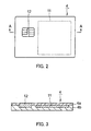
FIG. 2 is a plan view of an ID card used in the image information search system according to the embodiment of the present invention; -
FIG. 3 is a cross-sectional view which is cut by an A-A line shown inFIG. 2 ; -
FIG. 4 is a plan view of a non-contact IC tag arranged on the ID card; -
FIG. 5 is a system block diagram of the image information search system according to the embodiment of the present invention; -
FIG. 6 is a system block diagram of the image information search system according to the embodiment of the present invention; -
FIG. 7 is a diagram showing an example of information registered in an image information database of the image information search system according to the embodiment of the present invention; and -
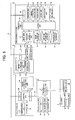
FIG. 8 is a flow chart showing a procedure of the image information search system according to the embodiment of the present invention. -
- 1
- Room in which room entrance is managed
- 2
- Electronics
- 2a
- Personal computer
- 2b
- Copy machine
- 2c
- Printer
- 3
- Imaging device
- 3a,3b,3c,3d
- Security cameras
- 4
- ID card
- 4a,4b
- Card base materials
- 5
- Reading device
- 5a,5b,5c,5d
- Card readers
- 6
- Electronics user
- 7
- Opening/closing door
- 8
- Communication circuit
- 9
- Processing device
- 10
- Locking management device
- 11
- Non-contact IC tag
- 12
- IC module
- 13
- Base material
- 15
- Conductive member
- 16C
- Coil connection terminal
- 17
- IC chip
- Now, a description will be given of the image information search system according to an embodiment of the present invention in details, with reference to the attached drawings.
-
FIG. 1 is a diagram for explaining the outline of the configuration of the image information search system according to the embodiment of the present invention.FIG. 2 is a plan view of the ID card used in the image information search system according to the embodiment of the present invention.FIG. 3 is a cross-sectional view which is cut by the cutting line A-A shown inFIG. 2 .FIG. 4 is a plan view of the non-contact IC tag provided on the ID card.FIG. 5 andFIG. 6 are system block diagrams of the image information search system according to the embodiment of the present invention.FIG. 7 is a table showing an example of information registered in the image information database of the image information search system according to the embodiment of the present invention.FIG. 8 is a flow chart showing a procedure of the image information search system according to the embodiment of the present invention. - As shown in
FIG. 1 , in the image information search system according to the embodiment of the present invention, aroom 1 in which room entrance is managed includesplural electronics 2 including apersonal computer 2a, acopy machine 2b, and aprinter 2c, and animaging device 3 includingsecurity cameras user 6 of theelectronics 2. - Moreover,
card readers reading devices 5 are connected to each of theelectronics 2. - The
card readers ID card 4 being the storage medium owned by theuser 6. - At an entrance/exit of the
room 1, an opening/closing door 7 whose locking is managed by theID card 4 is provided. Acard reader 5d for reading the employee ID number being the unique information stored on theID card 4 is provided on the outer side of the entrance/exit of theroom 1. - A
security camera 3d for shooting a video of the person entering theroom 1 from the entrance/exit thereof is further provided, and can shoot the entering person. - As shown in
FIG. 5 andFIG. 6 , theelectronics 2 such as thepersonal computer 2a, thecopy machine 2b and theprinter 2c, theimaging device 3 such as thecard reader 5d, thesecurity cameras locking management device 10 are connected to theprocessing device 9 including the computer by thecommunication line 8. - The
ID card 4 being the storage medium may be a storage medium: capable of storing the unique information capable of specifying the user of the electronics; and capable of making the reading device read the unique information. This point is not particularly limited. In the shown recording medium, such a case that the non-contact IC card having an IC module for contact is used is shown as an example. - As shown in
FIG. 2 to FIG. 4 , theID card 4 has such a configuration that anon-contact IC tag 11 is integrated inside thecard base materials IC module 12 is embedded. - The
non-contact IC tag 11 is also referred to as "non-contact data carrier" or "RFID", and a transmitting/receivingunit 20 including a coil pattern is formed on abase material 13 made of plastic, as shown inFIG. 4 . Thenon-contact IC tag 8 forms a resonant circuit with using a coil and a capacitative element to receive and transmit an acoustic wave of a constant frequency. - Additionally, as another system, power transmission and data transmission may be performed by electromagnetic induction of a carrier wave from a reader/writer. Generally, frequency bands of 135kHz (medium wave), 13.56MHz and 2.45GHz (micro wave) are used.
- In the case of the shown example, the transmitting/receiving
unit 14 including the coil pattern forms a jumping circuit on the rear side of thebase material 13 by acontinuity member 15, and is connected to a bump on the rear side of anIC chip 17 by a coil connection terminal 16C. TheIC chip 17 includes acontrol unit 18 serving as a CPU and astorage unit 19 serving as a memory. Thestorage unit 19 registers the employee ID number being the unique information. - In the shown example, the capacitative element is integrated in the
IC chip 17. Thenon-contact IC tag 11 is formed by forming the coil pattern by the photo etching or the etching after resist print of metallic foil such as aluminum foil laminated on a resin base material, mounting theIC chip 17, and providing a protective coating. The size can be a size equal to or smaller than 30mm×30mm. - The
resin base material 13 used for thenon-contact IC tag 11 can be made of various kinds of materials such as PET, polypropylene, polyethylene, polystyrene and nylon. Moreover, theresin base material 13 may be made of paper. Though thickness thereof can be 15-300 µm, 20-100 µm is preferred in consideration of the strength, the processing work property and the cost. Though copper foil, aluminum foil and iron foil can be used as the metallic foil, the aluminum foil is preferred in consideration of the cost and the processing property, and the thickness about 6-50 µm is preferred. - In reading the information recorded on the
non-contact IC tag 11, the card reader being the reading device sends a resonating calling signal to thenon-contact IC tag 11, and reads a response signal from thenon-contact IC tag 11. In addition, the card reader reads the information recorded in the memory of theIC chip 17 of thenon-contact IC tag 11. Thereby, reading the information is executed. - Next, a description will be given of the configuration of the image information search system according to this embodiment of the present invention in details, with reference to
FIG. 5 andFIG. 6 . - First, a
reading device 5 provided in theelectronics 2 includes a transmitting/receivingunit 21, astorage unit 22, acontrol unit 23 and an interface (I/F) 24. - The transmitting/receiving
unit 21 receives the employee ID number being the unique information from the transmitting/receivingunit 20 of theID card 4 without contact. - The
storage unit 22 includes management number being the identification information predetermined for managing each of theelectronics 2, and a control program. The control program is programmed to transmit the employee ID number being the unique information received by the transmitting/receivingunit 21 and the management number to theelectronics 2 via acommunication wire 25. - The
electronics 2 include acertification unit 26, astorage unit 27, a uniqueinformation transmitting unit 28, interfaces (I/F) 29 and 30 and acontrol unit 31. - Based on the employee I D number being the unique information received from the
reading device 5, thecertification unit 26 determines whether or not the user is the person permitted to use theelectronics 2. The determination method is to certificate the user in a case that, by a collation process with collation information stored in thestorage unit 27, a collation result of coincidence of both of the information is obtained. - The
electronics 2 are in a locked state and unusable until the certification in thecertification unit 26 is approved. When the certification is approved, the locking is released, and theelectronics 2 become usable. - When the locking of the
electronics 2 is released and theelectronics 2 become usable, the uniqueinformation transmitting unit 28 transmits the employee IDnumberbeing the unique information received from thereading device 5 to theprocessing device 9 via thecommunication line 8. - The
imaging device 3 includes animaging unit 32 having a detection function to automatically start shooting a video at the time of detecting the change of the picture image in the image area, an imageinformation transmitting unit 33, astorage unit 34, an interface (I/F) 35 and acontrol unit 36. - A specific image area capable of shooting the video is set to the
imaging unit 32 in advance, and the shooting area and the vicinity of the electronics can be shot. - The
storage unit 34 stores the control program and the management number being the identification information of theimaging device 3. - The image
information transmitting unit 33 has a function to transmit the image information shot by theimaging unit 32 and the management number to theprocessing device 9 via thecommunication circuit 8. - The electronics which can be shot by the
imaging device 3 may be one of the electronics, or the image area may be set in order to shoot the plural electronics. - The
processing device 9 includes aninput unit 37, adisplay unit 39, an interface (I/F) 40, aregister unit 41, an imageinformation choosing unit 42, astorage unit 43, aclock unit 44, acertification unit 45, a door lockingcontrol unit 46, acontrol unit 47, animage information database 48, anemployee information database 49, an imagingdevice information database 50 and an abnormalstate informing unit 58. - The employee ID number which is set for each employee, and information associated with the employee ID number, e.g., the name, the post, the department, the phone number and the company-joining date, are registered in the
employee information database 49 as the employee information. - In order to specify the electronics which can be imaged by each of the
imaging devices 3, information obtained by associating the management number being the identification information of each of theimaging devices 3 and the management number of the electronics which can be imaged by each of theimaging devices 3 is registered in the imagingdevice information database 50. - The
register unit 41 associates the employee ID number being the unique information received from theelectronics 2, the image information received from theimaging device 3, the clock information and the management number of the imaging device via thecommunication line 8, and registers them in theimage information database 48. - Further, based on the employee ID number being the unique information received from the
electronics 2, theregister unit 41 chooses the preset information out of the employee information registered in theemployee information database 49, and associates it with the employee ID number to register them in theimage information database 48. - In addition, the
clock unit 25 of theprocessing device 9 makes it clear what time the employee ID number being the unique information is received from theelectronics 2 via thecommunication line 8. The employee ID number and the image information received from theelectronics 2 are registered in theimage information database 48 so that the time of receiving of the employee ID number and the imaged time information of the image information received from theelectronics 2 coincide with each other. Namely, the employee specified by the employee ID number is seen in the picture imaged at the substantially same time as that of reading the employee ID number in thereading device 5. -
FIG. 7 shows an example of the information registered in theimage information database 48. As shown inFIG. 7 , as the information registered in theimage information database 48, the name, the department, the camera number, the camera setting place, the imaged time and the image information, associated with the employee ID number being the unique information, are registered. Therefore, when only the picture of the specific employee is chosen and seen, the image information of the employee can be easily displayed and seen on the display unit, based on the employee ID number and the name being the unique information. - In addition, the
display unit 39 has a function to display the unique information and the image information associated with each other and stored in theimage information database 48 of theprocessing device 9 as the same picture image. - Thereby, even when someone steals the storage medium of the other person and illegally uses it, by seeing and confirming the unique information and the image information displayed on the
display unit 39, it becomes possible to immediately confirm whether or not the illegal action is executed. - In such a case that the employee ID number is not read by the
card readers reading devices 5, instead of the employee ID number, "0" is registered as the identification information indicating that no employee ID number being the unique information is received. Thus, when "0" is registered in the space for originally registering the employee ID number, such a probability that a suspicious person is shot is predicted high. Therefore, when "0" is registered, the name and department of the employee are not registered. - Moreover, the
certification unit 45 has a function to execute the certification process of the employee ID number being the unique information received from thecard reader 5d used at the time of entering of theroom 1. When the certification is approved, the door lockingcontrol unit 46 transmits the instruction signal for releasing the locking of the opening/closing door to thelocking management device 10 via thecommunication line 8. - Additionally, in such a case that the image information of the specific employee is displayed on the
display unit 39 to be seen, the imageinformation choosing unit 42 chooses the image data associated with the employee ID number registered in theimage information database 48 out of the employee ID number being the unique information inputted from theinput unit 37 by the browser to be registered, based on the employee ID number being the unique information. Then, the imageinformation choosing unit 42 displays the unique information and the image information on thedisplay unit 39 as the same picture image. - The abnormal
state informing unit 58 has a function to inform the abnormal state in such a case that only the image information is received from theimaging device 3 and no unique information is received from the reading device. The function of informing the abnormal state is executed by various kinds of methods such as making an alarm sound, transmission of alarm information via e-mail and alarm display on the display unit. - As shown in
FIG. 6 , thecard reader 5d provided on the outer side of the entrance/exit of theroom 1 and thelocking management device 10 for managing the locking state of the opening/closing door 7 whose locking is managed are connected to thecommunication line 8. - The
card reader 5d includes a transmitting/receivingunit 51, astorage unit 52, acontrol unit 53 and an interface (I/F) 54. The transmitting/receivingunit 51 receives the employee ID number being the unique information from the transmitting/receivingunit 20 of theID card 4 without contact. - The
storage unit 52 includes the management number capable of specifying thecard reader 5d and the control program. The control program is programmed to transmit the employee ID number being the unique information received by the transmitting/receivingunit 51 and the management number to theprocessing device 9 via thecommunication line 8. - The
locking management device 10 includes a locking opening/closing unit 55 for varying the opening/closing state of the opening/closing door 7, acontrol unit 56 and an interface (I/F) 57. - When receiving the instruction signal for releasing the locking of the door from the
processing device 9 via thecommunication line 8, the locking opening/closing unit 55 releases the door locking, which makes it possible for the employee to enter the room. Thereby, it can be prevented that a person having noID card 4, such as a third person other than the employee, enters the room. - Next, a description will be given of the procedure of the image information management system according to the embodiment of the present invention, with reference to a flow chart shown in
FIG. 6 . - On detecting the change of the image by the entering of the person in the image area, the
imaging device 3 set at the entrance of the gate automatically starts shooting the video (step S1). Then, theimaging device 3 continues shooting the video for a predetermined time period from such a state that theimaging device 3 does not detect the change of the picture image in the image area, and automatically finishes shooting the video. The image information shot by theimaging device 3 is transmitted to the processing device 9 (step S2). - The employee ID number being the unique information stored on the
ID card 4 owned by the employee is read by thecard reader 5d being the reading device provided at the entrance of the gate (step S3). In such a case that the employee ID number is read, the identity certification is subsequently executed based on the employee ID number read by thecard reader 5d being the reading device (step S4). - When the identity certification is approved, the locking of the entrance door is released, and the room becomes enterable. At the same time, the employee ID number read by the
card reader 5d being the reading device and the reading device ID number capable of specifying thecard reader 5d being the reading device are transmitted to theprocessing device 9 from thecard reader 5d being the reading device (step S5). - When receiving the employee ID number and the reading device ID number, the
processing device 9 extracts the name and the department from the information registered in theemployee information database 49 based on the received employee ID number, by the register unit, and associates them with the employee ID number to register them into theimage information database 48. At the same time, based on the reading device ID number, theprocessing device 9 associates the image information received from the imaging device with the camera number, the camera setting place and the imaged time to register them (step S6). - On the other hand, in such a case that the
processing device 9 does not receive the employee ID number from theimaging device 3 within the predetermined time period from the time of receiving the image information from theimaging device 3, theprocessing device 9 associates the image information and the reading device ID information and stores them in theimage information database 48 being a storage unit of theprocessing device 9. At the same time, theprocessing device 9 associates the identification information of no-employee-ID-number-received indicating that no employee ID number is received, and stores them (step S7). The identification information indicating that no employee ID number is received may be optionally determined, and may be indicated as "0", for example. - By the above-mentioned process, the image information of the suspicious individual having no
ID card 4 can be associated with the identification information indicating that no employee ID number is received to be stored. When only the image information of the suspicious individual is extracted and checked, the image information can be easily extracted from the identification information. - In the above embodiment, such a case that the employee ID card owned by the employee is used as the storage medium is explained. However, the storage medium is not limited to the ID card. Namely, the storage medium is applicable to various kinds of storage media owned by the person, such as a ticket and a room key used in a hotel.
- The present invention provides a technique of executing use management of electronics and limitation of illegal use thereof, room entrance management, entrance management and visiting management with using a storage medium such as an IC card. Thus, the present invention is usable for various kinds of management such as use management of office facilities and security management of building.
Claims (4)
- An image information management system comprising:a reading device which reads unique information from a storage medium in which the unique information is stored;an imaging device which automatically starts shooting a video at a time of detecting a change of a picture image in an image area; anda processing device which includes a database which receives the unique information read by the reading device and the image information shot by the imaging device and associates the unique information and the image information to store the unique information and the image information,wherein the processing device includes a control unit which associates the unique information and the image information to store the unique information and the image information in the database in a case of receiving the unique information and the image information, and which associates the image information and identification information indicating that no unique information is received to store the image information and the identification information in the database in a case of receiving only the image information from the imaging device and no unique information from the reading device.
- The image information management system according to claim 1,
wherein the imaging device includes a storage unit which stores electronic identification information of specifying electronics existing in an image area shot by the imaging device, and a unit which transmits, to the processing device, not only the image information but also the electronic identification information at a time of transmitting the image information to the processing device. - The image information management system according to claim 1, wherein the processing device includes a unit which displays the unique information and the image information associated and stored in the database, as a same picture image.
- The image information management system according to claim 1, wherein the processing device includes an abnormal state informing unit which informs an abnormal state in a case of receiving only the image information from the imaging device and no unique information from the reading device.
Applications Claiming Priority (2)
| Application Number | Priority Date | Filing Date | Title |
|---|---|---|---|
| JP2005142313A JP4697942B2 (en) | 2005-05-16 | 2005-05-16 | Shooting information management system |
| PCT/JP2006/309690 WO2006123629A1 (en) | 2005-05-16 | 2006-05-16 | Imaging information management system |
Publications (3)
| Publication Number | Publication Date |
|---|---|
| EP1887801A1 true EP1887801A1 (en) | 2008-02-13 |
| EP1887801A4 EP1887801A4 (en) | 2010-09-29 |
| EP1887801B1 EP1887801B1 (en) | 2013-01-09 |
Family
ID=37431201
Family Applications (1)
| Application Number | Title | Priority Date | Filing Date |
|---|---|---|---|
| EP06746404A Ceased EP1887801B1 (en) | 2005-05-16 | 2006-05-16 | Imaging information management system |
Country Status (6)
| Country | Link |
|---|---|
| US (1) | US9262897B2 (en) |
| EP (1) | EP1887801B1 (en) |
| JP (1) | JP4697942B2 (en) |
| KR (1) | KR101201113B1 (en) |
| CN (1) | CN101176345B (en) |
| WO (1) | WO2006123629A1 (en) |
Families Citing this family (7)
| Publication number | Priority date | Publication date | Assignee | Title |
|---|---|---|---|---|
| EP2312487B1 (en) * | 2004-11-02 | 2016-09-28 | Dai Nippon Printing Co., Ltd. | Management system and management method |
| JP4773998B2 (en) * | 2007-03-15 | 2011-09-14 | 富士フイルム株式会社 | Surveillance camera system, moving image search device, face image database update device, and operation control method thereof |
| US20090237219A1 (en) * | 2008-03-21 | 2009-09-24 | Berlin Bradley M | Security apparatus, system and method of using same |
| KR101051365B1 (en) * | 2009-07-16 | 2011-07-22 | 주식회사 유니온커뮤니티 | Access control device with camera and access control method |
| WO2014014238A1 (en) * | 2012-07-17 | 2014-01-23 | Samsung Electronics Co., Ltd. | System and method for providing image |
| JPWO2015151980A1 (en) * | 2014-04-02 | 2017-04-13 | ソニー株式会社 | Information processing system and computer program |
| CN108447156A (en) * | 2018-03-14 | 2018-08-24 | 广州科坦电子技术有限公司 | A kind of hotel's smart lock |
Family Cites Families (15)
| Publication number | Priority date | Publication date | Assignee | Title |
|---|---|---|---|---|
| JP2793658B2 (en) * | 1988-12-28 | 1998-09-03 | 沖電気工業株式会社 | Automatic screening device |
| KR100248955B1 (en) | 1994-07-18 | 2000-03-15 | 유무성 | Automatic monitoring system |
| JPH09198577A (en) * | 1996-01-19 | 1997-07-31 | Nec Corp | Multimedia security system |
| JPH10222773A (en) * | 1997-01-31 | 1998-08-21 | U S C:Kk | Building security systems |
| JPH11313310A (en) * | 1998-04-30 | 1999-11-09 | Toshiba Corp | Plant monitoring equipment |
| JP2001167306A (en) * | 1999-12-09 | 2001-06-22 | Hitachi Kokusai Electric Inc | IC card management system |
| DE60119418T2 (en) * | 2000-03-22 | 2007-05-24 | Kabushiki Kaisha Toshiba, Kawasaki | Face-capturing recognition device and passport verification device |
| JP2001302133A (en) * | 2000-04-25 | 2001-10-31 | Hitachi Building Systems Co Ltd | Building security equipment |
| JP2004005511A (en) * | 2002-03-26 | 2004-01-08 | Toshiba Corp | Monitoring system, monitoring method and monitoring program |
| JP2004030022A (en) * | 2002-06-24 | 2004-01-29 | Shimizu Corp | Intrusion detection system |
| US6933849B2 (en) * | 2002-07-09 | 2005-08-23 | Fred Sawyer | Method and apparatus for tracking objects and people |
| JP2005051302A (en) * | 2003-07-29 | 2005-02-24 | Toyo Commun Equip Co Ltd | Image storage system and monitoring system using it |
| US7183895B2 (en) * | 2003-09-05 | 2007-02-27 | Honeywell International Inc. | System and method for dynamic stand-off biometric verification |
| CN1529290A (en) * | 2003-10-08 | 2004-09-15 | 李恩林 | Monitoring type antitheft alarming device and alarming process |
| US20060106930A1 (en) * | 2004-11-17 | 2006-05-18 | Shaffer James D | Method of querying for device location in a heterogeneous network |
-
2005
- 2005-05-16 JP JP2005142313A patent/JP4697942B2/en not_active Expired - Fee Related
-
2006
- 2006-05-16 CN CN2006800167234A patent/CN101176345B/en not_active Expired - Fee Related
- 2006-05-16 WO PCT/JP2006/309690 patent/WO2006123629A1/en not_active Ceased
- 2006-05-16 EP EP06746404A patent/EP1887801B1/en not_active Ceased
- 2006-05-16 US US11/914,479 patent/US9262897B2/en not_active Expired - Fee Related
- 2006-05-16 KR KR1020077029249A patent/KR101201113B1/en not_active Expired - Fee Related
Also Published As
| Publication number | Publication date |
|---|---|
| EP1887801A4 (en) | 2010-09-29 |
| WO2006123629A1 (en) | 2006-11-23 |
| CN101176345B (en) | 2013-06-05 |
| US9262897B2 (en) | 2016-02-16 |
| US20090027496A1 (en) | 2009-01-29 |
| EP1887801B1 (en) | 2013-01-09 |
| CN101176345A (en) | 2008-05-07 |
| KR101201113B1 (en) | 2012-11-20 |
| KR20080019000A (en) | 2008-02-29 |
| JP2006318351A (en) | 2006-11-24 |
| JP4697942B2 (en) | 2011-06-08 |
Similar Documents
| Publication | Publication Date | Title |
|---|---|---|
| US9753952B2 (en) | Image information management system and method thereof, and image information search system | |
| US8089341B2 (en) | Management system | |
| Singh et al. | Application of RFID technology in libraries | |
| CN110503515A (en) | A kind of book management system and method based on Radio Frequency Identification Technology | |
| US9262897B2 (en) | Image information management system | |
| EP1898362B1 (en) | Document management system | |
| US7388481B1 (en) | Method and apparatus for asset management in an open environment | |
| JP4752276B2 (en) | Shooting information retrieval system | |
| JP2006174200A (en) | Imaging information management system and method | |
| JP3952032B2 (en) | Asset take-out management system and asset take-out management program | |
| JP4857651B2 (en) | Goods management system | |
| JP2001162911A (en) | ID card issuing device | |
| JP2012156817A (en) | Image monitoring system | |
| JP2008046723A (en) | Administrator terminal, managed device, and management system | |
| JP4575343B2 (en) | Document management system and receiving apparatus | |
| EP4002242A1 (en) | Device for article with anti-theft tag | |
| JP4882589B2 (en) | Entrance / exit management device, managed device and management system | |
| JP2009211591A (en) | Document management system and program | |
| HK1176134A (en) | Management system | |
| HK1106840B (en) | Management system |
Legal Events
| Date | Code | Title | Description |
|---|---|---|---|
| PUAI | Public reference made under article 153(3) epc to a published international application that has entered the european phase |
Free format text: ORIGINAL CODE: 0009012 |
|
| 17P | Request for examination filed |
Effective date: 20071211 |
|
| AK | Designated contracting states |
Kind code of ref document: A1 Designated state(s): DE FR GB |
|
| DAX | Request for extension of the european patent (deleted) | ||
| RBV | Designated contracting states (corrected) |
Designated state(s): DE FR GB |
|
| A4 | Supplementary search report drawn up and despatched |
Effective date: 20100830 |
|
| 17Q | First examination report despatched |
Effective date: 20110426 |
|
| R17C | First examination report despatched (corrected) |
Effective date: 20110505 |
|
| REG | Reference to a national code |
Ref country code: DE Ref legal event code: R079 Ref document number: 602006034111 Country of ref document: DE Free format text: PREVIOUS MAIN CLASS: H04N0007180000 Ipc: G08B0013196000 |
|
| GRAP | Despatch of communication of intention to grant a patent |
Free format text: ORIGINAL CODE: EPIDOSNIGR1 |
|
| RIC1 | Information provided on ipc code assigned before grant |
Ipc: G07C 9/00 20060101ALI20120720BHEP Ipc: G08B 13/196 20060101AFI20120720BHEP |
|
| GRAS | Grant fee paid |
Free format text: ORIGINAL CODE: EPIDOSNIGR3 |
|
| GRAA | (expected) grant |
Free format text: ORIGINAL CODE: 0009210 |
|
| AK | Designated contracting states |
Kind code of ref document: B1 Designated state(s): DE FR GB |
|
| REG | Reference to a national code |
Ref country code: GB Ref legal event code: FG4D |
|
| REG | Reference to a national code |
Ref country code: DE Ref legal event code: R096 Ref document number: 602006034111 Country of ref document: DE Effective date: 20130307 |
|
| PLBE | No opposition filed within time limit |
Free format text: ORIGINAL CODE: 0009261 |
|
| STAA | Information on the status of an ep patent application or granted ep patent |
Free format text: STATUS: NO OPPOSITION FILED WITHIN TIME LIMIT |
|
| 26N | No opposition filed |
Effective date: 20131010 |
|
| REG | Reference to a national code |
Ref country code: DE Ref legal event code: R097 Ref document number: 602006034111 Country of ref document: DE Effective date: 20131010 |
|
| REG | Reference to a national code |
Ref country code: FR Ref legal event code: PLFP Year of fee payment: 11 |
|
| REG | Reference to a national code |
Ref country code: FR Ref legal event code: PLFP Year of fee payment: 12 |
|
| REG | Reference to a national code |
Ref country code: FR Ref legal event code: PLFP Year of fee payment: 13 |
|
| PGFP | Annual fee paid to national office [announced via postgrant information from national office to epo] |
Ref country code: DE Payment date: 20180522 Year of fee payment: 13 |
|
| PGFP | Annual fee paid to national office [announced via postgrant information from national office to epo] |
Ref country code: FR Payment date: 20180522 Year of fee payment: 13 |
|
| PGFP | Annual fee paid to national office [announced via postgrant information from national office to epo] |
Ref country code: GB Payment date: 20180518 Year of fee payment: 13 |
|
| REG | Reference to a national code |
Ref country code: DE Ref legal event code: R119 Ref document number: 602006034111 Country of ref document: DE |
|
| GBPC | Gb: european patent ceased through non-payment of renewal fee |
Effective date: 20190516 |
|
| PG25 | Lapsed in a contracting state [announced via postgrant information from national office to epo] |
Ref country code: GB Free format text: LAPSE BECAUSE OF NON-PAYMENT OF DUE FEES Effective date: 20190516 Ref country code: DE Free format text: LAPSE BECAUSE OF NON-PAYMENT OF DUE FEES Effective date: 20191203 |
|
| PG25 | Lapsed in a contracting state [announced via postgrant information from national office to epo] |
Ref country code: FR Free format text: LAPSE BECAUSE OF NON-PAYMENT OF DUE FEES Effective date: 20190531 |