EP1887260A2 - Continuously variable transmission - Google Patents
Continuously variable transmission Download PDFInfo
- Publication number
- EP1887260A2 EP1887260A2 EP07253125A EP07253125A EP1887260A2 EP 1887260 A2 EP1887260 A2 EP 1887260A2 EP 07253125 A EP07253125 A EP 07253125A EP 07253125 A EP07253125 A EP 07253125A EP 1887260 A2 EP1887260 A2 EP 1887260A2
- Authority
- EP
- European Patent Office
- Prior art keywords
- controller
- belt
- sheave
- flange
- vehicle
- Prior art date
- Legal status (The legal status is an assumption and is not a legal conclusion. Google has not performed a legal analysis and makes no representation as to the accuracy of the status listed.)
- Granted
Links
Images


Classifications
-
- F—MECHANICAL ENGINEERING; LIGHTING; HEATING; WEAPONS; BLASTING
- F16—ENGINEERING ELEMENTS AND UNITS; GENERAL MEASURES FOR PRODUCING AND MAINTAINING EFFECTIVE FUNCTIONING OF MACHINES OR INSTALLATIONS; THERMAL INSULATION IN GENERAL
- F16H—GEARING
- F16H61/00—Control functions within control units of change-speed- or reversing-gearings for conveying rotary motion ; Control of exclusively fluid gearing, friction gearing, gearings with endless flexible members or other particular types of gearing
- F16H61/66—Control functions within control units of change-speed- or reversing-gearings for conveying rotary motion ; Control of exclusively fluid gearing, friction gearing, gearings with endless flexible members or other particular types of gearing specially adapted for continuously variable gearings
- F16H61/662—Control functions within control units of change-speed- or reversing-gearings for conveying rotary motion ; Control of exclusively fluid gearing, friction gearing, gearings with endless flexible members or other particular types of gearing specially adapted for continuously variable gearings with endless flexible members
- F16H61/66254—Control functions within control units of change-speed- or reversing-gearings for conveying rotary motion ; Control of exclusively fluid gearing, friction gearing, gearings with endless flexible members or other particular types of gearing specially adapted for continuously variable gearings with endless flexible members controlling of shifting being influenced by a signal derived from the engine and the main coupling
- F16H61/66259—Control functions within control units of change-speed- or reversing-gearings for conveying rotary motion ; Control of exclusively fluid gearing, friction gearing, gearings with endless flexible members or other particular types of gearing specially adapted for continuously variable gearings with endless flexible members controlling of shifting being influenced by a signal derived from the engine and the main coupling using electrical or electronical sensing or control means
-
- F—MECHANICAL ENGINEERING; LIGHTING; HEATING; WEAPONS; BLASTING
- F16—ENGINEERING ELEMENTS AND UNITS; GENERAL MEASURES FOR PRODUCING AND MAINTAINING EFFECTIVE FUNCTIONING OF MACHINES OR INSTALLATIONS; THERMAL INSULATION IN GENERAL
- F16H—GEARING
- F16H61/00—Control functions within control units of change-speed- or reversing-gearings for conveying rotary motion ; Control of exclusively fluid gearing, friction gearing, gearings with endless flexible members or other particular types of gearing
- F16H61/02—Control functions within control units of change-speed- or reversing-gearings for conveying rotary motion ; Control of exclusively fluid gearing, friction gearing, gearings with endless flexible members or other particular types of gearing characterised by the signals used
- F16H61/0202—Control functions within control units of change-speed- or reversing-gearings for conveying rotary motion ; Control of exclusively fluid gearing, friction gearing, gearings with endless flexible members or other particular types of gearing characterised by the signals used the signals being electric
- F16H61/0204—Control functions within control units of change-speed- or reversing-gearings for conveying rotary motion ; Control of exclusively fluid gearing, friction gearing, gearings with endless flexible members or other particular types of gearing characterised by the signals used the signals being electric for gearshift control, e.g. control functions for performing shifting or generation of shift signal
- F16H61/0213—Control functions within control units of change-speed- or reversing-gearings for conveying rotary motion ; Control of exclusively fluid gearing, friction gearing, gearings with endless flexible members or other particular types of gearing characterised by the signals used the signals being electric for gearshift control, e.g. control functions for performing shifting or generation of shift signal characterised by the method for generating shift signals
- F16H2061/0241—Adapting the ratio to special transmission conditions, e.g. shifts during warming up phase of transmission when fluid viscosity is high
-
- F—MECHANICAL ENGINEERING; LIGHTING; HEATING; WEAPONS; BLASTING
- F16—ENGINEERING ELEMENTS AND UNITS; GENERAL MEASURES FOR PRODUCING AND MAINTAINING EFFECTIVE FUNCTIONING OF MACHINES OR INSTALLATIONS; THERMAL INSULATION IN GENERAL
- F16H—GEARING
- F16H2312/00—Driving activities
- F16H2312/02—Driving off
Definitions
- This invention relates to a continuously variable transmission, in particular to a belt type of continuously variable transmission electronically controlled by a controller.
- the V-belt type of continuously variable transmission is widely in use on vehicles, particularly two-wheeled vehicles, such as a scooted type of two wheeled vehicle.
- This V-belt type of continuously variable transmission is made up of a primary sheave disposed on a primary shaft for receiving output of a power source, such as an engine, and a secondary sheave disposed on a secondary shaft for the output to be taken out to a drive wheel, wherein a V-belt is routed around both sheaves.
- the transmission ratio between both sheaves may be continuously changed by changing groove widths of respective sheaves via a groove width regulating mechanism, thereby regulating the routing radii of the V-belt on the sheaves.
- each of the primary sheave and the secondary sheave with a fixed flange and a movable flange to form a V-groove therebetween.
- Each movable flange is freely movable on a respective shaft and the transmission ratio may be continuously regulated by moving the movable flanges by means of the groove width regulating mechanism.
- a continuously variable transmission of this kind may utilise an electric motor to regulate the groove widths.
- the movable flange of at least the primary sheave may be moved in both directions to narrow (toward top ratio) and widen (toward low ratio)the primary sheave groove width by the motion thrust of the electric motor, the groove widths may be regulated freely.
- Such an arrangement is disclosed in JP-3043061 .
- Other examples are disclosed in JP-H7-86383 and JP-A-H4-157242 .
- roller weights disposed inside the primary sheave move outward due to centrifugal force and press and cause the movable flange on the primary sheave side to move.
- the groove width of each sheave is regulated by the balance between the pressing force of the roller weights of the primary sheave and the force of a spring and a torque cam of the secondary sheave.
- the displacement of the movable sheave on the primary sheave side is controlled with the electric motor.
- the vehicle speed exceeds a specified value, to hold the movable flange to a position (low position) in which the primary sheave groove width becomes the maximum.
- the electric motor does not work until the vehicle speed reaches a specified value, and the movable flange on the primary sheave side remains fixed to the low position, so that no belt pressing force is produced. Therefore, even if the belt on the primary sheave side moves in a slackening direction, the movable sheave cannot follow the motion. Therefore, the belt might flutter. If the belt flutters at the time of start, the rider may have uncomfortable feeling because of vibration caused by the flutter, or the flutter may cause an unusual noise or a loud noise.
- a main object of the invention is to provide a straddle type of vehicle in which the fluttering motion of the belt is prevented or at least minimised at the time of starting a vehicle.
- a continuously variable transmission for a vehicle comprising:
- the controller may be adapted to control the actuator to move the moveable flange of the primary sheave in a direction to increase the width of the belt groove after the belt groove is initially moved in a direction to decrease the width of the belt groove. Accordingly, after the initial load is applied to the belt by decreasing the groove width, the groove width may then be increased once again to release this initial load.
- the controller may be adapted to control the actuator to move the moveable flange of the primary sheave in a direction to increase the width of the belt groove on the basis of a specified condition.
- the specified condition comprises an increase in vehicle speed above a predetermined value.
- the transmission may further comprise a vehicle speed sensor coupled to the controller and adapted to detect the speed of the vehicle and output a signal to the controller when the vehicle speed increase above the predetermined value.
- the specified condition may comprise an elapsed time period from the a throttle opening sensor outputting a signal to the controller when the throttle is switched from a closed state to an open state.
- the secondary sheave may comprise a fixed flange and a moveable flange which define a groove therebetween for accommodating the endless belt, wherein the moveable flange of the secondary sheave may be biased towards a direction to decrease the groove width.
- the moveable flange of the secondary sheave may be biased with a spring and a torque cam.
- a continuously variable transmission electronically controlled by a controller characterized in that the continuously variable transmission is of a belt type and has a belt routed around V-grooves of a primary sheave and a secondary sheave to continuously change transmission ratio by changing the groove widths of the respective sheaves, the primary sheave is made up of a fixed flange and a movable flange attached to a rotary shaft, the groove width of the primary sheave is regulated with the motion of the movable flange of the primary sheave controlled by an actuator, the actuator is connected to the controller, to which a throttle opening degree sensor for detecting the opening degree of throttle is connected, the throttle opening degree sensor outputs to the controller at least a signal produced when the throttle opening degree is switched from closed state to open state, and at the time a vehicle starts from the standing state, the controller, on the basis of the signal generated when the throttle opening degree is switched from closed state to open state, controls the actuator so as to move the movable
- the controller is characterized to control the actuator so as to move the movable flange that has moved toward the direction of decreasing the groove width of the primary sheave back to the ordinary position on the basis of a specified condition.
- a vehicle speed sensor for detecting the vehicle speed is connected to the controller, and the specified condition is the time the vehicle speed detected with the vehicle speed sensor exceeds a threshold value.
- the specified condition is the time a specified period of time has elapsed after the throttle opening degree is switched from closed state to open state.
- the secondary sheave is made up of a fixed flange and a movable flange attached to a rotary shaft, and the movable flange of the secondary sheave is urged with a spring and a torque cam toward the direction of decreasing the groove width.
- the movable flange that has moved toward the direction of decreasing the groove width may be pressing the belt routed around the V-groove of the primary sheave.
- the controller controls the electric motor on the basis of the signal generated when the throttle opening degree switches from closed state to open state so as to move the movable flange on the primary sheave side from the ordinary position (low position) in the standing state of the vehicle toward the direction (toward the top side) of decreasing the groove width of the primary sheave.
- the electric motor controlled by the controller pushes the movable flange of the primary sheave from the low position toward the top side. Because it is possible to apply load on the belt routed around the primary sheave side by pushing the movable flange of the primary sheave from the low position toward the top side, it is possible to prevent the belt from fluttering at the time the vehicle starts.
- a vehicle comprising a continuously variable transmission according any one of the first and second aspects.
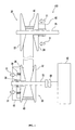
- Fig. 1 is a schematic illustration of a basic arrangement of the belt type of continuously variable transmission 100.
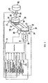
- Fig. 2 is a block diagram representation of the continuously variable transmission 100.
- the continuously variable transmission 100 is of a belt type and comprises: a primary sheave 20, a secondary sheave 30, and a belt 40 routed around the V-grooves of both sheaves 20 and 30.
- the primary sheave 20 is connected to an engine 80.
- the secondary sheave 30 is connected to a rear wheel 82 through a centrifugal clutch 85 and a final speed reduction mechanism 84.
- the drive force of the engine 80 outputted according to accelerator operation is transmitted to the primary sheave 20 and converted with the primary sheave 20 into rotary force of the belt 40.
- the centrifugal clutch 85 is connected, and the rotary force of the belt 40 is transmitted to the rear wheel 82 through the secondary sheave 30 and the final speed reduction mechanism 84 to drive the rear wheel 82.
- the primary sheave 20 and the secondary sheave 30 of this embodiment are respectively made up of fixed flanges 22, 32 and movable flanges 24, 34 attached respectively to rotary shafts 25, 35. Both movable flanges 24, 34 are provided respectively to be movable in an axial direction relative to a respective rotary shaft 25, 35.
- the fixed flange is also called as the fixed sheave
- the movable flange is also called as the movable sheave.
- the movable flange 34 of the secondary sheave 30 is urged with a spring 36 in the direction of narrowing the groove width(in the direction of arrow 31).
- a torque cam 38 is provided in a position of the movable flange 34 of the secondary sheave 30 for applying thrust in the axial direction of the movable flange 34 according to the difference between the torque of the fixed flange 32 and the torque of the movable flange 34.
- the torque cam 38 is made up of a cam groove formed on the movable flange 34 side and a guide pin formed on the rotary shaft 35 side to be slidably inserted into the cam groove.
- the torque cam 38 has only to be of a constitution integral with the movable flange 34 or the rotary shaft 35 to produce thrust.
- the groove width of the primary sheave 20 is regulated by motion of the movable flange 24 of the primary sheave 20 which is controlled by an actuator 60. Because it is possible to move the movable flange 24 either in the direction of narrowing the groove width (toward the top side) or in the direction of widening the groove width (toward the low side) of the primary sheave 20, the groove width can be regulated freely.
- Figure 1 represents a configuration of the transmission 100 when the vehicle is in a standing state (in the state of the vehicle speed of 0 km/h).
- the transmission ratio of the continuously variable transmission 100 is normally low (maximum transmission ratio).
- the groove width of the primary sheave 20 is the widest, while the groove width of the secondary sheave 30 is the narrowest.
- the groove width of the primary sheave 20 narrows to increase the routing radius of the belt 40.
- the belt 40 on the secondary sheave 30 side is pulled.
- the tension on the belt 40 exceeds the urging force of the spring 36
- the groove width of the secondary sheave 30 is widened.
- the routing radius of the belt 40 on the secondary sheave 30 side decreases. In effect, the transmission ratio decreases (shifts toward the top side).
- Fig. 2 is a block diagram illustrating the constitution of the continuously variable transmission 100 of this embodiment.
- the actuator 60 for regulating the groove width of the primary sheave 20 is electrically connected to the controller (speed changing controller) 10.
- the actuator 60 of this embodiment comprises an electric motor.
- the electric motor 60 is controlled by, for example, PWM (pulse-width modulation) output.
- the controller 10 is provided with an ECU (electronic control unit).
- the electronic control unit (ECU) is provided with, for example, a microcomputer (MPU). It should be understood that the actuator 60 may comprise other components than an electric motor, such as stepping motor, linear motor, solenoid, hydraulic system, or pneumatic system or the like for regulating the groove width of the primary sheave 20.
- a throttle opening degree sensor for detecting the opening degree of a throttle (not shown) is also connected electrically to the controller 10.
- the throttle opening degree sensor is capable of outputting to the controller 10 a signal (throttle opening degree signal) produced at least when the throttle opening degree switches from a closed state to an open state.
- the controller 10 is adapted to be capable of controlling the electric motor 60, on the basis of the signal produced when the throttle opening degree switches from a closed state to an open state, to move the movable flange 24 of the primary sheave 20 from the normal position (low position) of the movable flange in the standing state of the vehicle toward the direction of narrowing the groove width of the primary sheave 20 (toward the top side).
- the controller 10 at the time of the start, controls the electric motor 60 so as to press the movable flange 24 from the normal, low position toward the top side.
- the controller 10 controls the electric motor 60, on the basis of the signal produced when the opening degree of the throttle switches from a closed state to an open state, to move the movable flange 24 of the primary sheave 20 from the normal position (low position) toward the direction of narrowing the groove width of the primary sheave 20 (toward the top side).
- the movable flange 24 is pressed from the normal, low position toward the top side with the electric motor 60 controlled by the controller 10.
- a load is applied in the direction of arrow 21 (Fig. 1) to the belt 40, so that the tension on the belt 40 increases.
- fluttering of the belt 40 due to torque variation at the time the vehicle starts is prevented, making it possible to reduce vibration and noise at the time the vehicle starts.
- the position of the movable flange 24 pressed toward the top side is set to a position that permits to press the belt 40 appropriately to the extent that the transmission ratio does not change and that permits to prevent the belt from fluttering at the time of start. Specifically, it is the position that permits to apply a load to the belt to the extent the external shape of the belt deforms slightly. For example, it is a position shifted from the low position toward the top side by 0.2 mm.
- the position of the movable flange 24 may be set to any appropriate position according to the condition of use.
- a condition or a belt load starting condition is set on which the movable flange 24 in the low position is pressed toward the top side on the basis of the signal produced when the throttle opening degree switches from a closed state to an open state.
- the signal for starting a load is not limited to the information of the throttle opening degree sensor.
- the vehicle of this embodiment is provided with the controller 10 (transmission ratio controller) as a central component of a control system for controlling the transmission ratio of the continuously variable transmission 100.
- the controller 10 transmission ratio controller
- the controller 10 is adapted to control the electric motor 60 so as to move the movable flange 24, that has moved toward the direction of narrowing the groove width of the primary sheave 20, back to the normal position (low position) on the basis of a specified condition.
- the removal condition of a belt load of this embodiment is set on the basis of information of the vehicle speed sensor for detecting the vehicle speed. Specifically, when the vehicle starts, the controller 10 controls the electric motor 60 so as to move the movable flange 24, that has moved toward the direction of narrowing the groove width of the primary sheave 20 when the vehicle speed detected by the vehicle speed sensor exceeds a threshold value, back to the normal position (low position). By this control, the movable flange 24 having moved toward the top side returns again to the low position, and the load temporarily applied to the belt 40 is removed.
- the threshold value of the vehicle speed is determined on the basis of the vehicle speed range in which the belt 40 may possibly flutter due to torque variation when the vehicle starts. That is, in the range of very low vehicle speed below the threshold value, the movable flange 24 cannot follow the slackening motion of the belt 40 and so the flutter of the belt 40 is possible. In the vehicle speed range above the threshold value, however, as a belt thrust occurs along with increase in the vehicle speed, the belt flutter subsides by itself. For example, with the constitution of this embodiment, the belt flutter may subside at vehicle speeds of 4 km/h and over, in which case the threshold value is set to 4 km/h or more. This threshold value may be appropriately set according to vehicle constitution, drive condition, and the like.
- the vehicle speed sensor for detecting the vehicle speed is electrically connected to the controller 10.
- the vehicle speed sensor of this embodiment is a rear wheel revolution sensor 83 for detecting the revolution of the rear wheel 82.
- the rear wheel revolution sensor 83 is disposed in the vicinity of the rear wheel 82 and connected electrically to the controller 10 to output rear wheel revolution signals to the controller 10.
- any sensor other than the rear wheel revolution sensor 83 may be used as long as it is capable of detecting revolution signals in proportion to the vehicle speed.
- a secondary sheave revolution sensor 37 for detecting the revolution of the secondary sheave 30 may be used.
- a constitution is possible in which both of these sensors are used.
- the removal condition of a belt load is set on the basis of vehicle speed information in the above example, the removal condition may be based on information other than the vehicle speed because the belt flutter subsides once the belt thrust occurs after the start.
- the controller 10 may control the electric motor 60 so as to move the movable flange 24, having moved in the direction of narrowing the groove width of the primary sheave 20, back to the normal position (low position) when a specified period of time has elapsed after the throttle opening degree switched from closed state to open state.
- the vehicle speed after the lapse of the specified period of time at least has only to be out of the very low vehicle speed range in which the belt 40 flutters due to torque variation.
- a timer time may be set to 0.3 seconds after the throttle is opened. The timer time may be appropriately set according to the condition of use.
- the removal condition of a belt load may be otherwise preset as a pattern of instruction to the electric motor 60 rather than predetermining on the basis of information physically detected with a sensor or the like. Specifically, while the controller 10 outputs an instruction for pressing the movable flange 24 from the low position toward the top side when the vehicle starts, it is possible to include in the output signal an instruction for moving the movable flange 24 back to the normal low position.
- connection and disconnection of a starting clutch either active control type or passive control type (centrifugal clutch, etc.) is usable
- connection of the centrifugal clutch 85 may be adopted as the removal condition.
- connection or disconnection of the clutch 85 is determined by a detecting a twist amount (phase difference between two specified points) of the rotary shaft 35 to which the centrifugal clutch 85 is attached.
- the belt slip amount may be obtained by comparing the transmission ratio determined from the position of the movable sheave 24 of the primary sheave 20 with the transmission ratio calculated from the detected actual values of revolution of the primary sheave 20 and the secondary sheave 30.
- the belt tension it is possible to place, between the primary sheave 20 and the secondary sheave 30, a member such as a tensioning member that absorbs belt deflection, and measure the belt tension by detecting the reaction force from the belt to that member.
- the belt load is removed according to the actual measurement of the vehicle speed, it is possible to securely maintain the belt load until the vehicle speed exceeds the very low vehicle speed range (from 0 km/h to the threshold value) even in a situation in which sufficient vehicle speed is not obtained as when starting on an uphill, so that prevention of the belt flutter is actually effected.
- a sheave position detector 27 for detecting the position of the movable flange 24 of the primary sheave 20 is connected to the controller 10.
- the sheave position detector 27 is capable of outputting information on the movable flange position (sheave position signal) to the controller 10.
- the controller 10 controls the electric motor 60 on the basis of information on the flange position (sheave position signal).
- an engine revolution sensor 18 for detecting the revolution of the engine 80 and a primary sheave revolution sensor (not shown) for detecting the revolution of the primary sheave 20, respectively outputting engine revolution signal and primary sheave revolution signal to the controller 10.
- a main switch signal and a handlebar switch signal To the controller 10 may also be inputted a main switch signal and a handlebar switch signal.
- the controller 10 of this embodiment is the one implementing overall control of the engine 80 and the continuously variable transmission 100 on the basis of the various signals described above. Specifically, a target transmission ratio is obtained while calculating vehicle speed and acceleration based on the throttle opening degree signal, secondary sheave revolution, drive wheel revolution signal, sheave position signal, etc. And the controller 10 controls actual transmission ratio of the straddle type of vehicle by implementing the so-called ordinary transmission control in which the position of the movable flange 24 of the primary sheave 20 is controlled by driving the electric motor 60 so as to realize the target transmission ratio.
- the ordinary transmission control is a control in which a transmission ratio corresponding to the drive condition (vehicle speed, throttle opening degree, etc.) of the vehicle is calculated from a pre-registered map, a transmission instruction for realizing the transmission ratio is given to the continuously variable transmission 100, and finally the transmission ratio is realized.
- the ordinary transmission control is adapted to realize smooth acceleration and deceleration by decreasing the transmission ratio (controls toward the top side) as the vehicle speed and throttle opening degree increase, and increasing the transmission ratio (controls toward the low side) as the vehicle speed and throttle opening degree decrease.
- Fig. 3 shows an example vehicle on which the continuously variable transmission 100 of this embodiment is mounted.
- the vehicle 1000 comprises: the drive source 80; the continuously variable transmission 100 connected to the drive source 80; and the controller 10 (not shown in Fig. 3) for electronically controlling the continuously variable transmission 100.
- the vehicle 1000 is a scooter type of motorcycle.
- the drive source 80 of this embodiment is an engine.
- the output of the engine 80 is regulated according to an accelerator operation member operated by a rider.
- the accelerator operation member is a throttle grip attached to a handlebar.
- the primary sheave 20 is connected to the engine 80, and the secondary sheave 30 is connected through the final speed reduction mechanism 84 to the rear wheel 82.
- the drive force of the engine 80 outputted according to the throttle operation is converted into rotary force of the belt 40 through the primary sheave 20.
- the rotary force of the belt 40 is transmitted through the secondary sheave 30 to the rear wheel 82 to drive the rear wheel 82.
- the vehicle on which the continuously variable transmission 100 may be mounted is not limited to the straddle type of vehicle.
- the continuously variable transmission 100 may be mounted on such a vehicle as an SSV (side by side vehicle) with seats for two persons to ride on.
- the controller 10 determines a target transmission ratio based on the vehicle speed, the engine revolution, the accelerator opening degree, etc., calculates the position of the movable flange 24 of the primary sheave 20 (target flange position) for realizing the target transmission ratio, and calculates the displacement amount of the movable flange 24.
- the target transmission ratio may be either a fixed value different by a certain amount from the present transmission ratio or a value that changes gradually according to the vehicle speed, engine revolution, and accelerator opening degree at each time point.
- the movable flange 24 is controlled to maintain the low state. In other words, the target flange position is set to the low position.
- the controller 10 determines whether or not the vehicle is currently in the standing state (step S102). If the vehicle is not in the standing state, the controller 10 controls to move the movable flange 24 to the target flange position so that the transmission ratio becomes the target transmission ratio (step S105). Thereafter, the controller 10 implements the ordinary transmission control based on the ordinary map.
- the controller 10 confirms information of the throttle opening degree sensor to determine whether or not the throttle opening degree has switched from closed state to open state (step 5103). In case the throttle has not switched from closed state to open state, for example in case the throttle is already open, the controller 10 moves the movable flange 24 to the target flange position to control so that the transmission ratio becomes the target transmission ratio (step S105). Thereafter, the controller 10 implements the ordinary transmission control based on the ordinary map.
- the controller 10 changes the target flange position calculated in the step S101 to a specified preload target position and rewrites it (step S104). After that, the process moves to the step S105 to move the movable flange 24 to the target flange position changed to the preload target position (step S105). The movable flange 24 moved to the preload target position thereafter controlled to maintain the preload target position until a specified belt load removal condition is inputted.
- the specified preload target position is the position shifted toward the top side from the normal movable-flange position (low position) in the standing state of the vehicle. This position is set to an appropriate position so that the movable flange 24 having moved to the preload target position can apply a load to the belt 40 and the transmission ratio is not affected.
- the preload target position is a position at which the movable flange 24 may be pressed to the extent that the belt 40 slightly deforms by the load, for example in this embodiment a position shifted from the low position toward the top side by about 0.2 mm.
- the controller 10 determines whether or not the specified removal condition of a belt load is met. For example, a case in which the removal condition is determined on the basis of vehicle speed is described. Whether or not the current vehicle speed has exceeded a threshold value is determined. In case the current vehicle speed has not exceeded the threshold value, the controller 10 remains holding the movable flange 24 in the preload target position. After that, in case the vehicle speed increases and exceeds the threshold value, the controller 10 controls to move the movable flange 24 to the target flange position so that the transmission ratio becomes the target transmission ratio.
- the movable flange 24 When the vehicle starts, the movable flange 24 is controlled to maintain the low state determined from a pre-registered map until the vehicle speed exceeds a specified value (for example 15 km/h).
- a specified value for example 15 km/h.
- the vehicle speed threshold value of the removal condition of a belt load is set for example to 4 km/h as described above, very low in comparison with the specified value described above. Therefore, the target flange position that can be calculated after the vehicle speed exceeds the threshold value is always set to the low position.
- the movable flange 24 having once moved to the preload target position thereafter controlled to move back again to the low position when the vehicle speed exceeds the threshold value.
- Fig. 5 is a graph of the relationship of the movable flange position and the vehicle speed when the vehicle starts from the standing state.
- the vertical axis represents values corresponding to respective curves, and the horizontal axis represents the time.
- the curve 90 represents throttle opening degree; the curve 91, the vehicle speed; the line 92, the threshold value of the vehicle speed; the curve 93, the actual position of the movable flange; the line 94, the target flange position; and the line 95, the preload target position.
- This invention makes it possible to provide a straddle type of vehicle in which the belt is prevented from fluttering when the vehicle starts.
Landscapes
- Engineering & Computer Science (AREA)
- General Engineering & Computer Science (AREA)
- Mechanical Engineering (AREA)
- Control Of Transmission Device (AREA)
- Transmissions By Endless Flexible Members (AREA)
Abstract
Description
- This invention relates to a continuously variable transmission, in particular to a belt type of continuously variable transmission electronically controlled by a controller.
- The V-belt type of continuously variable transmission is widely in use on vehicles, particularly two-wheeled vehicles, such as a scooted type of two wheeled vehicle. This V-belt type of continuously variable transmission is made up of a primary sheave disposed on a primary shaft for receiving output of a power source, such as an engine, and a secondary sheave disposed on a secondary shaft for the output to be taken out to a drive wheel, wherein a V-belt is routed around both sheaves. The transmission ratio between both sheaves may be continuously changed by changing groove widths of respective sheaves via a groove width regulating mechanism, thereby regulating the routing radii of the V-belt on the sheaves.
- It is common practice to constitute each of the primary sheave and the secondary sheave with a fixed flange and a movable flange to form a V-groove therebetween. Each movable flange is freely movable on a respective shaft and the transmission ratio may be continuously regulated by moving the movable flanges by means of the groove width regulating mechanism.
- A continuously variable transmission of this kind may utilise an electric motor to regulate the groove widths. As the movable flange of at least the primary sheave may be moved in both directions to narrow (toward top ratio) and widen (toward low ratio)the primary sheave groove width by the motion thrust of the electric motor, the groove widths may be regulated freely. Such an arrangement is disclosed in
JP-3043061 JP-H7-86383 JP-A-H4-157242 - On a vehicle equipped with a mechanical, belt type of continuously variable transmission, roller weights disposed inside the primary sheave move outward due to centrifugal force and press and cause the movable flange on the primary sheave side to move. The groove width of each sheave is regulated by the balance between the pressing force of the roller weights of the primary sheave and the force of a spring and a torque cam of the secondary sheave.
- With the above described arrangement, because centrifugal force works on the roller weights along with the rotation of the primary sheave caused by engine torque, belt pressing force on the primary sheave side is produced immediately following an increase in the engine revolution at the time of start. By the pressing force, the belt routed around both sheaves becomes taut, so that the belt does not flutter due to variations in torque at the time of start.
- On the other hand, on a vehicle equipped with an electronic, belt type of continuously variable transmission, while the displacement of the movable flange on the secondary sheave side is effected by belt pressing force of the spring and the torque cam, as in the mechanical continuously variable transmission, the displacement of the movable sheave on the primary sheave side is controlled with the electric motor. When starting the vehicle, it is controlled, until the vehicle speed exceeds a specified value, to hold the movable flange to a position (low position) in which the primary sheave groove width becomes the maximum.
- With the above arrangement, the electric motor does not work until the vehicle speed reaches a specified value, and the movable flange on the primary sheave side remains fixed to the low position, so that no belt pressing force is produced. Therefore, even if the belt on the primary sheave side moves in a slackening direction, the movable sheave cannot follow the motion. Therefore, the belt might flutter. If the belt flutters at the time of start, the rider may have uncomfortable feeling because of vibration caused by the flutter, or the flutter may cause an unusual noise or a loud noise.
- A main object of the invention is to provide a straddle type of vehicle in which the fluttering motion of the belt is prevented or at least minimised at the time of starting a vehicle.
- According to a first aspect of the present invention, there is provided a continuously variable transmission for a vehicle, comprising:
- a primary sheave adapted to be rotatably coupled to a secondary sheave via an endless belt, the primary sheave comprising a fixed flange and a moveable flange defining a belt groove therebetween for accommodating the endless belt;
- a controller;
- a throttle opening sensor connected to the controller and associated with a vehicle throttle, wherein the throttle opening sensor is adapted to output a signal to the controller at least when the throttle is switched from a closed state to an open state; and
- an actuator connected to the controller and adapted to move the moveable flange of the primary sheave relative to the fixed flange to vary the width of the belt groove and vary the transmission ratio between the primary sheave and the secondary sheave, wherein, when an associated vehicle begins motion from a standing state and the throttle opening sensor outputs a signal to the controller indicating that the throttle is switched from a closed state to an open state, the actuator is adapted to be activated by the controller to move the moveable flange in a direction to decrease the width of the belt groove of the primary sheave.
- Accordingly, as the moveable flange of the primary sheave is moved to decrease the groove width, this will have the effect of pressing against the endless belt, which may be a V-belt, to therefore provide an initial load to assist to minimize or prevent fluttering of the belt.
- The controller may be adapted to control the actuator to move the moveable flange of the primary sheave in a direction to increase the width of the belt groove after the belt groove is initially moved in a direction to decrease the width of the belt groove. Accordingly, after the initial load is applied to the belt by decreasing the groove width, the groove width may then be increased once again to release this initial load.
- The controller may be adapted to control the actuator to move the moveable flange of the primary sheave in a direction to increase the width of the belt groove on the basis of a specified condition.
- The specified condition comprises an increase in vehicle speed above a predetermined value. The transmission may further comprise a vehicle speed sensor coupled to the controller and adapted to detect the speed of the vehicle and output a signal to the controller when the vehicle speed increase above the predetermined value.
- Alternatively, or additionally, the specified condition may comprise an elapsed time period from the a throttle opening sensor outputting a signal to the controller when the throttle is switched from a closed state to an open state.
- The secondary sheave may comprise a fixed flange and a moveable flange which define a groove therebetween for accommodating the endless belt, wherein the moveable flange of the secondary sheave may be biased towards a direction to decrease the groove width. The moveable flange of the secondary sheave may be biased with a spring and a torque cam.
- According to a second aspect of the present invention, there is provided a continuously variable transmission electronically controlled by a controller, characterized in that the continuously variable transmission is of a belt type and has a belt routed around V-grooves of a primary sheave and a secondary sheave to continuously change transmission ratio by changing the groove widths of the respective sheaves, the primary sheave is made up of a fixed flange and a movable flange attached to a rotary shaft, the groove width of the primary sheave is regulated with the motion of the movable flange of the primary sheave controlled by an actuator, the actuator is connected to the controller, to which a throttle opening degree sensor for detecting the opening degree of throttle is connected, the throttle opening degree sensor outputs to the controller at least a signal produced when the throttle opening degree is switched from closed state to open state, and at the time a vehicle starts from the standing state, the controller, on the basis of the signal generated when the throttle opening degree is switched from closed state to open state, controls the actuator so as to move the movable flange from an ordinary position in the standing state of the vehicle toward the direction of decreasing the groove width of the primary sheave.
- In one embodiment, the controller is characterized to control the actuator so as to move the movable flange that has moved toward the direction of decreasing the groove width of the primary sheave back to the ordinary position on the basis of a specified condition.
- In one embodiment, a vehicle speed sensor for detecting the vehicle speed is connected to the controller, and the specified condition is the time the vehicle speed detected with the vehicle speed sensor exceeds a threshold value.
- In one embodiment, the specified condition is the time a specified period of time has elapsed after the throttle opening degree is switched from closed state to open state.
- In one embodiment, the secondary sheave is made up of a fixed flange and a movable flange attached to a rotary shaft, and the movable flange of the secondary sheave is urged with a spring and a torque cam toward the direction of decreasing the groove width.
- At the time the vehicle starts from the standing state, the movable flange that has moved toward the direction of decreasing the groove width may be pressing the belt routed around the V-groove of the primary sheave.
- According to the invention, in the continuously variable transmission electronically controlled by the controller, at the time the vehicle starts from the standing state, the controller controls the electric motor on the basis of the signal generated when the throttle opening degree switches from closed state to open state so as to move the movable flange on the primary sheave side from the ordinary position (low position) in the standing state of the vehicle toward the direction (toward the top side) of decreasing the groove width of the primary sheave. In other words, at the time of starting, the electric motor controlled by the controller pushes the movable flange of the primary sheave from the low position toward the top side. Because it is possible to apply load on the belt routed around the primary sheave side by pushing the movable flange of the primary sheave from the low position toward the top side, it is possible to prevent the belt from fluttering at the time the vehicle starts.
- According to a third aspect of the present invention there is provided a vehicle comprising a continuously variable transmission according any one of the first and second aspects.
- These and other aspects of the present invention will now be described, by way of example only, with reference to the accompanying drawings, in which:
- Fig. 1 is a schematic illustration of a basic constitution of the continuously variable transmission according to an embodiment of the present invention;
- Fig. 2 is a block diagram representation of the continuously variable transmission of Fig. 1;
- Fig. 3 is an external side view of a straddle type of vehicle incorporating the continuously variable transmission of Fig. 1;
- Fig. 4 a flowchart showing the process flow of a controller of the continuously variable transmission; and
- Fig. 5 is a graph showing the relationship of the flange position, etc. at the time of initiating movement of the vehicle from standing state.
- Before a detailed description of the exemplary embodiment of the present invention is given, it should be noted that the present inventor has been working on the development of an electronic, belt type of continuously variable transmission for electronically controlling the transmission ratio by effecting the displacement of the movable flange on the primary sheave side with an electric motor, and found a problem that, when a vehicle starts from the standing state, the belt makes a fluttering motion, so that the vehicle cannot be started smoothly. Such fluttering of the belt in the starting stage of a vehicle was not recognized with the mechanical type of continuously variable transmission in which the displacement of the movable flange is effected by pressing the roller weights by centrifugal force. Therefore, the inventor eagerly examined the cause of the flutter occurring only with the electronic type of continuously variable transmission in spite of little difference in starting action between electronic and mechanical types, and obtained the following findings.
- With the mechanical type of continuously variable transmission, as the centrifugal force works on the roller weights immediately when engine torque is transmitted and the primary sheave rotates, the belt pressing force on the primary sheave side is always produced according to the rise in the engine revolution. Therefore, even if the belt bounces due to torque variation at the time of start, it is held down with the pressing force of the movable flange and brought into taut state, so that the belt does not flutter.
- With the electronic type of continuously variable transmission, however, as the electric motor does not work until the vehicle speed exceeds a specified value and the movable flange on the primary sheave side remains fixed in the low position, the belt pressing force on the primary sheave side does not occur. Therefore, when the belt on the primary sheave side bounces due to torque change when starting, the movable flange cannot follow the bouncing motion and as such fluttering of the belt occurs.
- The inventor found out it is possible to realize a mechanism for preventing the belt from fluttering even with the electronic continuously variable transmission if a control is implemented as with the mechanical type in which tension is applied to the belt when starting, or a control that produces a belt pressing force, and devised the present invention.
- An embodiment of the invention will be hereinafter described with reference to appended figures. In the figures shown hereinafter, components and parts of the same function are provided with the same symbols and explained. The invention is not limited to the embodiment below.
- An arrangement of a continuously
variable transmission 100 as an embodiment of the invention will be hereinafter described with reference to Figs. 1 and 2. Fig. 1 is a schematic illustration of a basic arrangement of the belt type of continuouslyvariable transmission 100. Fig. 2 is a block diagram representation of the continuouslyvariable transmission 100. - The continuously
variable transmission 100 is of a belt type and comprises: aprimary sheave 20, asecondary sheave 30, and abelt 40 routed around the V-grooves of bothsheaves belt 40 on respective sheaves is regulated, thereby regulating continuously the transmission ratio between both the sheaves. - The
primary sheave 20 is connected to anengine 80. Thesecondary sheave 30 is connected to arear wheel 82 through a centrifugal clutch 85 and a finalspeed reduction mechanism 84. The drive force of theengine 80 outputted according to accelerator operation is transmitted to theprimary sheave 20 and converted with theprimary sheave 20 into rotary force of thebelt 40. Then, as the rotary force of thebelt 40 increases, the centrifugal clutch 85 is connected, and the rotary force of thebelt 40 is transmitted to therear wheel 82 through thesecondary sheave 30 and the finalspeed reduction mechanism 84 to drive therear wheel 82. - The
primary sheave 20 and thesecondary sheave 30 of this embodiment are respectively made up of fixedflanges movable flanges rotary shafts movable flanges rotary shaft - The
movable flange 34 of thesecondary sheave 30 is urged with aspring 36 in the direction of narrowing the groove width(in the direction of arrow 31). Atorque cam 38 is provided in a position of themovable flange 34 of thesecondary sheave 30 for applying thrust in the axial direction of themovable flange 34 according to the difference between the torque of the fixedflange 32 and the torque of themovable flange 34. Thetorque cam 38 is made up of a cam groove formed on themovable flange 34 side and a guide pin formed on therotary shaft 35 side to be slidably inserted into the cam groove. Thetorque cam 38 has only to be of a constitution integral with themovable flange 34 or therotary shaft 35 to produce thrust. - On the other hand, the groove width of the
primary sheave 20 is regulated by motion of themovable flange 24 of theprimary sheave 20 which is controlled by anactuator 60. Because it is possible to move themovable flange 24 either in the direction of narrowing the groove width (toward the top side) or in the direction of widening the groove width (toward the low side) of theprimary sheave 20, the groove width can be regulated freely. - Figure 1 represents a configuration of the
transmission 100 when the vehicle is in a standing state (in the state of the vehicle speed of 0 km/h). In this case, the transmission ratio of the continuouslyvariable transmission 100 is normally low (maximum transmission ratio). When the transmission ratio is low, the groove width of theprimary sheave 20 is the widest, while the groove width of thesecondary sheave 30 is the narrowest. Along with the increase in the vehicle speed after a start, the groove width of theprimary sheave 20 narrows to increase the routing radius of thebelt 40. Then, as the tension on thebelt 40 increases, thebelt 40 on thesecondary sheave 30 side is pulled. When the tension on thebelt 40 exceeds the urging force of thespring 36, the groove width of thesecondary sheave 30 is widened. As a result, the routing radius of thebelt 40 on thesecondary sheave 30 side decreases. In effect, the transmission ratio decreases (shifts toward the top side). - A
controller 10 of this embodiment will now be described with reference to Fig. 2, in addition to Fig. 1. Fig. 2 is a block diagram illustrating the constitution of the continuouslyvariable transmission 100 of this embodiment. - The
actuator 60 for regulating the groove width of theprimary sheave 20 is electrically connected to the controller (speed changing controller) 10. Theactuator 60 of this embodiment comprises an electric motor. Theelectric motor 60 is controlled by, for example, PWM (pulse-width modulation) output. Thecontroller 10 is provided with an ECU (electronic control unit). The electronic control unit (ECU) is provided with, for example, a microcomputer (MPU). It should be understood that theactuator 60 may comprise other components than an electric motor, such as stepping motor, linear motor, solenoid, hydraulic system, or pneumatic system or the like for regulating the groove width of theprimary sheave 20. - A throttle opening degree sensor (not shown) for detecting the opening degree of a throttle (not shown) is also connected electrically to the
controller 10. The throttle opening degree sensor is capable of outputting to the controller 10 a signal (throttle opening degree signal) produced at least when the throttle opening degree switches from a closed state to an open state. - The
controller 10 is adapted to be capable of controlling theelectric motor 60, on the basis of the signal produced when the throttle opening degree switches from a closed state to an open state, to move themovable flange 24 of theprimary sheave 20 from the normal position (low position) of the movable flange in the standing state of the vehicle toward the direction of narrowing the groove width of the primary sheave 20 (toward the top side). In effect, thecontroller 10, at the time of the start, controls theelectric motor 60 so as to press themovable flange 24 from the normal, low position toward the top side. - With the constitution of this embodiment, when the vehicle starts from the standing state (the state of the vehicle speed of 0 km/h), the
controller 10 controls theelectric motor 60, on the basis of the signal produced when the opening degree of the throttle switches from a closed state to an open state, to move themovable flange 24 of theprimary sheave 20 from the normal position (low position) toward the direction of narrowing the groove width of the primary sheave 20 (toward the top side). In other words, when the vehicle starts, themovable flange 24 is pressed from the normal, low position toward the top side with theelectric motor 60 controlled by thecontroller 10. As themovable flange 24 is pressed toward the top side, a load is applied in the direction of arrow 21 (Fig. 1) to thebelt 40, so that the tension on thebelt 40 increases. As the tension increases, fluttering of thebelt 40 due to torque variation at the time the vehicle starts is prevented, making it possible to reduce vibration and noise at the time the vehicle starts. - Incidentally, with this embodiment, the position of the
movable flange 24 pressed toward the top side is set to a position that permits to press thebelt 40 appropriately to the extent that the transmission ratio does not change and that permits to prevent the belt from fluttering at the time of start. Specifically, it is the position that permits to apply a load to the belt to the extent the external shape of the belt deforms slightly. For example, it is a position shifted from the low position toward the top side by 0.2 mm. However, the position of themovable flange 24 may be set to any appropriate position according to the condition of use. - Also with this embodiment, a condition or a belt load starting condition is set on which the
movable flange 24 in the low position is pressed toward the top side on the basis of the signal produced when the throttle opening degree switches from a closed state to an open state. However, as long as a certain load is applied when the vehicle speed is very low at the time of start, it is possible to prevent thebelt 40 from fluttering. Therefore, the signal for starting a load is not limited to the information of the throttle opening degree sensor. For example, it is possible to set the belt load starting condition on the basis of information of the vehicle speed sensor for detecting the vehicle speed. - The constitution around the
controller 10 and the condition of removing the load on the belt will now be described with reference to Fig. 2. - The vehicle of this embodiment is provided with the controller 10 (transmission ratio controller) as a central component of a control system for controlling the transmission ratio of the continuously
variable transmission 100. - The
controller 10 is adapted to control theelectric motor 60 so as to move themovable flange 24, that has moved toward the direction of narrowing the groove width of theprimary sheave 20, back to the normal position (low position) on the basis of a specified condition. - By instantaneously moving the
movable flange 24 back to the normal low position, after it is once pressed to thebelt 40, or making an action of moving back thebelt 40, a quasi damping action may be effected. Therefore, it is possible not only to prevent thebelt 40 from fluttering but absorb the flutter of thebelt 40. This further ensures the effect of preventing the belt flutter at the time of start. - Moreover, as an action of moving back the
movable flange 24 is made instantaneously, there is no possibility of change in transmission ratio of the continuouslyvariable transmission 100 and of an adverse effect on starting performance. - The condition of moving the
movable flange 24, which has been pushed toward the top side, back to the normal low position, or the removal condition of a belt load, will now be described. The removal condition of a belt load of this embodiment is set on the basis of information of the vehicle speed sensor for detecting the vehicle speed. Specifically, when the vehicle starts, thecontroller 10 controls theelectric motor 60 so as to move themovable flange 24, that has moved toward the direction of narrowing the groove width of theprimary sheave 20 when the vehicle speed detected by the vehicle speed sensor exceeds a threshold value, back to the normal position (low position). By this control, themovable flange 24 having moved toward the top side returns again to the low position, and the load temporarily applied to thebelt 40 is removed. - In this embodiment, the threshold value of the vehicle speed is determined on the basis of the vehicle speed range in which the
belt 40 may possibly flutter due to torque variation when the vehicle starts. That is, in the range of very low vehicle speed below the threshold value, themovable flange 24 cannot follow the slackening motion of thebelt 40 and so the flutter of thebelt 40 is possible. In the vehicle speed range above the threshold value, however, as a belt thrust occurs along with increase in the vehicle speed, the belt flutter subsides by itself. For example, with the constitution of this embodiment, the belt flutter may subside at vehicle speeds of 4 km/h and over, in which case the threshold value is set to 4 km/h or more. This threshold value may be appropriately set according to vehicle constitution, drive condition, and the like. - The vehicle speed sensor for detecting the vehicle speed is electrically connected to the
controller 10. The vehicle speed sensor of this embodiment is a rear wheel revolution sensor 83 for detecting the revolution of therear wheel 82. The rear wheel revolution sensor 83 is disposed in the vicinity of therear wheel 82 and connected electrically to thecontroller 10 to output rear wheel revolution signals to thecontroller 10. - While this embodiment uses the rear wheel revolution sensor 83 for detecting directly the revolution of the
rear wheel 82, any sensor other than the rear wheel revolution sensor 83 may be used as long as it is capable of detecting revolution signals in proportion to the vehicle speed. For example, a secondarysheave revolution sensor 37 for detecting the revolution of thesecondary sheave 30 may be used. Or, a constitution is possible in which both of these sensors are used. - Further, while the removal condition of a belt load is set on the basis of vehicle speed information in the above example, the removal condition may be based on information other than the vehicle speed because the belt flutter subsides once the belt thrust occurs after the start.
- For example, it is possible to preset the removal condition of a belt load with a timer. Specifically, when the vehicle starts, the
controller 10 may control theelectric motor 60 so as to move themovable flange 24, having moved in the direction of narrowing the groove width of theprimary sheave 20, back to the normal position (low position) when a specified period of time has elapsed after the throttle opening degree switched from closed state to open state. In this case, the vehicle speed after the lapse of the specified period of time at least has only to be out of the very low vehicle speed range in which thebelt 40 flutters due to torque variation. For example, a timer time may be set to 0.3 seconds after the throttle is opened. The timer time may be appropriately set according to the condition of use. - The removal condition of a belt load may be otherwise preset as a pattern of instruction to the
electric motor 60 rather than predetermining on the basis of information physically detected with a sensor or the like. Specifically, while thecontroller 10 outputs an instruction for pressing themovable flange 24 from the low position toward the top side when the vehicle starts, it is possible to include in the output signal an instruction for moving themovable flange 24 back to the normal low position. - Besides the above examples, it is possible for example to detect the connection and disconnection of a starting clutch (either active control type or passive control type (centrifugal clutch, etc.) is usable) to remove the belt load according the signal produced when the starting clutch is connected. In the example shown in Fig. 2, connection of the centrifugal clutch 85 may be adopted as the removal condition. In that case, connection or disconnection of the clutch 85 is determined by a detecting a twist amount (phase difference between two specified points) of the
rotary shaft 35 to which the centrifugal clutch 85 is attached. - Still alternatively, it is possible to utilize any information obtained from the rider's operation when the rider gives up a start (such information as on throttle closing operation or brake applying operation) as a signal for the belt load removal.
- It is further possible to measure physical variation amount such as the amount of belt slip, torque variation, or torque tension variation, and to set to remove belt load when the variation amount falls within a specified range. To specifically describe the methods of detecting respective variation amounts, the belt slip amount may be obtained by comparing the transmission ratio determined from the position of the
movable sheave 24 of theprimary sheave 20 with the transmission ratio calculated from the detected actual values of revolution of theprimary sheave 20 and thesecondary sheave 30. As for the belt tension, it is possible to place, between theprimary sheave 20 and thesecondary sheave 30, a member such as a tensioning member that absorbs belt deflection, and measure the belt tension by detecting the reaction force from the belt to that member. - Among the removal conditions of a belt load described above, it is most preferable to be based on the vehicle speed information. In case that the belt load is removed according to the actual measurement of the vehicle speed, it is possible to securely maintain the belt load until the vehicle speed exceeds the very low vehicle speed range (from 0 km/h to the threshold value) even in a situation in which sufficient vehicle speed is not obtained as when starting on an uphill, so that prevention of the belt flutter is actually effected.
- The
controller 10 of this embodiment will now be described. A sheave position detector 27 for detecting the position of themovable flange 24 of theprimary sheave 20 is connected to thecontroller 10. The sheave position detector 27 is capable of outputting information on the movable flange position (sheave position signal) to thecontroller 10. Thecontroller 10 controls theelectric motor 60 on the basis of information on the flange position (sheave position signal). - To the
controller 10 are electrically connected an engine revolution sensor 18 for detecting the revolution of theengine 80 and a primary sheave revolution sensor (not shown) for detecting the revolution of theprimary sheave 20, respectively outputting engine revolution signal and primary sheave revolution signal to thecontroller 10. To thecontroller 10 may also be inputted a main switch signal and a handlebar switch signal. - The
controller 10 of this embodiment is the one implementing overall control of theengine 80 and the continuouslyvariable transmission 100 on the basis of the various signals described above. Specifically, a target transmission ratio is obtained while calculating vehicle speed and acceleration based on the throttle opening degree signal, secondary sheave revolution, drive wheel revolution signal, sheave position signal, etc. And thecontroller 10 controls actual transmission ratio of the straddle type of vehicle by implementing the so-called ordinary transmission control in which the position of themovable flange 24 of theprimary sheave 20 is controlled by driving theelectric motor 60 so as to realize the target transmission ratio. - The ordinary transmission control is a control in which a transmission ratio corresponding to the drive condition (vehicle speed, throttle opening degree, etc.) of the vehicle is calculated from a pre-registered map, a transmission instruction for realizing the transmission ratio is given to the continuously
variable transmission 100, and finally the transmission ratio is realized. The ordinary transmission control is adapted to realize smooth acceleration and deceleration by decreasing the transmission ratio (controls toward the top side) as the vehicle speed and throttle opening degree increase, and increasing the transmission ratio (controls toward the low side) as the vehicle speed and throttle opening degree decrease. - Fig. 3 shows an example vehicle on which the continuously
variable transmission 100 of this embodiment is mounted. Thevehicle 1000 comprises: thedrive source 80; the continuouslyvariable transmission 100 connected to thedrive source 80; and the controller 10 (not shown in Fig. 3) for electronically controlling the continuouslyvariable transmission 100. In this embodiment, thevehicle 1000 is a scooter type of motorcycle. Thedrive source 80 of this embodiment is an engine. The output of theengine 80 is regulated according to an accelerator operation member operated by a rider. In the present case of the scooter type, the accelerator operation member is a throttle grip attached to a handlebar. - In the continuously
variable transmission 100, theprimary sheave 20 is connected to theengine 80, and thesecondary sheave 30 is connected through the finalspeed reduction mechanism 84 to therear wheel 82. The drive force of theengine 80 outputted according to the throttle operation is converted into rotary force of thebelt 40 through theprimary sheave 20. The rotary force of thebelt 40 is transmitted through thesecondary sheave 30 to therear wheel 82 to drive therear wheel 82. - While the above embodiment shows only the straddle type of vehicle as an example, any vehicle with the continuously
variable transmission 100 mounted thereon can prevent belt flutter at the time of start by the constitution of this invention. Therefore, the vehicle on which the continuouslyvariable transmission 100 may be mounted is not limited to the straddle type of vehicle. For example, the continuouslyvariable transmission 100 may be mounted on such a vehicle as an SSV (side by side vehicle) with seats for two persons to ride on. - The control flow process of the
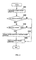
controller 10 will now be described with reference to the flowchart of Fig. 4. First, in the step S101, thecontroller 10 determines a target transmission ratio based on the vehicle speed, the engine revolution, the accelerator opening degree, etc., calculates the position of themovable flange 24 of the primary sheave 20 (target flange position) for realizing the target transmission ratio, and calculates the displacement amount of themovable flange 24. The target transmission ratio may be either a fixed value different by a certain amount from the present transmission ratio or a value that changes gradually according to the vehicle speed, engine revolution, and accelerator opening degree at each time point. In the standing state of the vehicle (the state of the vehicle speed of 0), themovable flange 24 is controlled to maintain the low state. In other words, the target flange position is set to the low position. - Next, the
controller 10 determines whether or not the vehicle is currently in the standing state (step S102). If the vehicle is not in the standing state, thecontroller 10 controls to move themovable flange 24 to the target flange position so that the transmission ratio becomes the target transmission ratio (step S105). Thereafter, thecontroller 10 implements the ordinary transmission control based on the ordinary map. - In case the vehicle is in the standing state, the
controller 10 confirms information of the throttle opening degree sensor to determine whether or not the throttle opening degree has switched from closed state to open state (step 5103). In case the throttle has not switched from closed state to open state, for example in case the throttle is already open, thecontroller 10 moves themovable flange 24 to the target flange position to control so that the transmission ratio becomes the target transmission ratio (step S105). Thereafter, thecontroller 10 implements the ordinary transmission control based on the ordinary map. - On the other hand, in case the throttle has switched from closed state to open state, the
controller 10 changes the target flange position calculated in the step S101 to a specified preload target position and rewrites it (step S104). After that, the process moves to the step S105 to move themovable flange 24 to the target flange position changed to the preload target position (step S105). Themovable flange 24 moved to the preload target position thereafter controlled to maintain the preload target position until a specified belt load removal condition is inputted. - Here, the specified preload target position is the position shifted toward the top side from the normal movable-flange position (low position) in the standing state of the vehicle. This position is set to an appropriate position so that the
movable flange 24 having moved to the preload target position can apply a load to thebelt 40 and the transmission ratio is not affected. Specifically , the preload target position is a position at which themovable flange 24 may be pressed to the extent that thebelt 40 slightly deforms by the load, for example in this embodiment a position shifted from the low position toward the top side by about 0.2 mm. - Removal of load from the
belt 40 will now be described. Thecontroller 10 determines whether or not the specified removal condition of a belt load is met. For example, a case in which the removal condition is determined on the basis of vehicle speed is described. Whether or not the current vehicle speed has exceeded a threshold value is determined. In case the current vehicle speed has not exceeded the threshold value, thecontroller 10 remains holding themovable flange 24 in the preload target position. After that, in case the vehicle speed increases and exceeds the threshold value, thecontroller 10 controls to move themovable flange 24 to the target flange position so that the transmission ratio becomes the target transmission ratio. - When the vehicle starts, the
movable flange 24 is controlled to maintain the low state determined from a pre-registered map until the vehicle speed exceeds a specified value (for example 15 km/h). On the other hand, the vehicle speed threshold value of the removal condition of a belt load is set for example to 4 km/h as described above, very low in comparison with the specified value described above. Therefore, the target flange position that can be calculated after the vehicle speed exceeds the threshold value is always set to the low position. As a result, themovable flange 24 having once moved to the preload target position thereafter controlled to move back again to the low position when the vehicle speed exceeds the threshold value. - Fig. 5 is a graph of the relationship of the movable flange position and the vehicle speed when the vehicle starts from the standing state. The vertical axis represents values corresponding to respective curves, and the horizontal axis represents the time. The
curve 90 represents throttle opening degree; thecurve 91, the vehicle speed; theline 92, the threshold value of the vehicle speed; the curve 93, the actual position of the movable flange; theline 94, the target flange position; and theline 95, the preload target position. - When the throttle is opened to start the vehicle from the standing state, the
movable flange 24 in the low position starts moving toward the preload target position indicated with theline 95. As a result, temporary load application onto thebelt 40 is started. As thebelt 40 becomes taut and transmission of torque to therear wheel 82 begins, therear wheel 82 rotates to start rising vehicle speed. The speed is detected. When the vehicle speed exceeds the threshold value, the temporary load on thebelt 40 is removed, and themovable flange 24 in the preload target position starts moving toward the low position. Controlling in this way makes it possible to shift the movable flange temporarily from the low position toward the top side. So it is possible to apply load to thebelt 40. - While the invention is described by way of preferable embodiments, the above description is not restrictive but may be modified in various ways as a matter of course.
- This invention makes it possible to provide a straddle type of vehicle in which the belt is prevented from fluttering when the vehicle starts.
-
- 10:
- controller
- 18:
- engine revolution sensor
- 20:
- primary sheave
- 21:
- arrow
- 24:
- movable flange
- 25:
- rotary shaft
- 27:
- sheave position detector
- 30:
- secondary sheave
- 31:
- arrow
- 32:
- fixed flange
- 34:
- movable flange
- 35:
- rotary shaft
- 36:
- spring
- 37:
- secondary sheave revolution sensor
- 38:
- torque cam
- 40:
- belt
- 60:
- actuator
- 80:
- engine
- 82:
- rear wheel
- 83:
- rear wheel revolution sensor
- 84:
- final speed reduction mechanism
- 85:
- centrifugal clutch
- 90:
- throttle opening degree curve
- 91:
- vehicle speed curve
- 92:
- vehicle speed threshold value line
- 93:
- measurement curve of movable flange position
- 94:
- target flange position line
- 95:
- preload target position line
- 100:
- continuously variable transmission
- 1000:
- vehicle
Claims (15)
- A continuously variable transmission (100) for a vehicle (1000), comprising:a primary sheave (20) adapted to be rotatably coupled to a secondary sheave (30) via an endless belt (40), the primary sheave (20) comprising a fixed flange (22) and a moveable flange (24) defining a belt groove therebetween for accommodating the endless belt (40);a controller (10);a throttle opening sensor connected to the controller (10) and associated with a vehicle throttle, wherein the throttle opening sensor is adapted to output a signal to the controller (10) at least when the throttle is switched from a closed state to an open state; andan actuator (60) connected to the controller (10) and adapted to move the moveable flange (24) of the primary sheave (20) relative to the fixed flange (22) to vary the width of the belt groove and vary the transmission ratio between the primary sheave (20) and the secondary sheave (30), wherein, when an associated vehicle (1000) begins motion from a standing state and the throttle opening sensor outputs a signal to the controller (10) indicating that the throttle is switched from a closed state to an open state, the actuator (60) is adapted to be activated by the controller (10) to move the moveable flange (24) in a direction to decrease the width of the belt groove of the primary sheave (20).
- The transmission (100) of Claim 1, wherein the controller (10) is adapted to control the actuator (60) to move the moveable flange (24) of the primary sheave (20) in a direction to increase the width of the belt groove after the belt groove is initially moved in a direction to decrease the width of the belt groove.
- The transmission (100) of Claim 2, wherein the controller (10) is adapted to control the actuator (60) to move the moveable flange (24) of the primary sheave (20) in a direction to increase the width of the belt groove on the basis of a specified condition.
- The transmission (100) of Claim 3, wherein the specified condition comprises an increase in vehicle speed above a predetermined value.
- The transmission (100) of Claim 4, further comprising a vehicle speed sensor coupled to the controller (10) and adapted to detect the speed of the vehicle (1000) and output a signal to the controller (10) when the vehicle speed increase above the predetermined value.
- The transmission (100) of Claim 3, 4 or 5, wherein the specified condition comprises an elapsed time period from the a throttle opening sensor outputting a signal to the controller (10) when the throttle is switched from a closed state to an open state.
- The transmission (100) of any preceding Claim, wherein the secondary sheave (30) comprises a fixed flange (32) and a moveable flange (34) which define a groove therebetween for accommodating the endless belt (40), wherein the moveable flange (34) of the secondary sheave (30) is biased towards a direction to decrease the groove width.
- The transmission (100) of Claim 7, wherein the moveable flange (34) of the secondary sheave (30) is biased with a spring (36) and a torque cam (38).
- A continuously variable transmission (100) electronically controlled by a controller (10), wherein
the continuously variable transmission (100) is of a belt type and has a belt (40) routed around V-grooves of a primary sheave (20) and a secondary sheave (30) to continuously change transmission ratio by changing the groove widths of the respective sheaves (20, 30),
the primary sheave (20) is made up of a fixed flange (22) and a movable flange (24) attached to a rotary shaft (25),
the groove width of the primary sheave (20) is regulated by controlling the motion of the movable flange (24) of the primary sheave (20) with an actuator (60),
the actuator (60) is connected to the controller (10),
to the controller (10) is connected a throttle opening degree sensor for detecting the opening degree of a throttle,
the throttle opening degree sensor outputs to the controller (10) a signal produced at least when the throttle opening degree is switched from closed state to open state, and
at the time a vehicle (1000) starts from the standing state, the controller (10), on the basis of the signal produced when the throttle opening degree is switched from closed state to open state, controls the actuator (60) so as to move the movable flange (24) from an ordinary position in the standing state of the vehicle (1000) toward the direction of decreasing the groove width of the primary sheave (20). - The continuously variable transmission (100) of Claim 9, wherein the controller (10) controls the actuator (60) so as to move the movable flange (24) that has moved toward the direction of decreasing the groove width of the primary sheave (20) back to the ordinary movable sheave position on the basis of a specified condition.
- The continuously variable transmission (100) of Claim 10, wherein a vehicle speed sensor for detecting the vehicle speed is connected to the controller (10), and wherein the specified condition is the time the vehicle speed detected with the vehicle speed sensor exceeds a threshold value.
- The continuously variable transmission (100) of Claim 10 or 11, wherein the specified condition is the time a specified period of time has elapsed after the throttle opening degree is switched from closed state to open state.
- The continuously variable transmission (100) of any of Claims 9 to 13, wherein
the secondary sheave (30) is made up of a fixed flange (32) and a movable flange (34) attached to a rotary shaft (35), and
the movable flange (34) of the secondary sheave (30) is urged with a spring (36) and a torque cam (38) toward the direction of decreasing the groove width. - The continuously variable transmission (100) of any of Claims 9 to 13, wherein, at the time the vehicle (1000) starts from the standing state, the movable flange (24) that has moved toward the direction of decreasing the groove width is pressing the belt (40) routed around the V-groove of the primary sheave (20).
- A vehicle (1000) comprising a continuously variable transmission (100) of any preceding claim.
Applications Claiming Priority (1)
| Application Number | Priority Date | Filing Date | Title |
|---|---|---|---|
| JP2006218999A JP2008045576A (en) | 2006-08-10 | 2006-08-10 | Continuously variable transmission |
Publications (3)
| Publication Number | Publication Date |
|---|---|
| EP1887260A2 true EP1887260A2 (en) | 2008-02-13 |
| EP1887260A3 EP1887260A3 (en) | 2010-06-23 |
| EP1887260B1 EP1887260B1 (en) | 2011-10-19 |
Family
ID=38621243
Family Applications (1)
| Application Number | Title | Priority Date | Filing Date |
|---|---|---|---|
| EP07253125A Active EP1887260B1 (en) | 2006-08-10 | 2007-08-09 | Continuously variable transmission |
Country Status (7)
| Country | Link |
|---|---|
| US (1) | US8439797B2 (en) |
| EP (1) | EP1887260B1 (en) |
| JP (1) | JP2008045576A (en) |
| CN (1) | CN100540957C (en) |
| AT (1) | ATE529667T1 (en) |
| ES (1) | ES2373330T3 (en) |
| TW (1) | TWI320829B (en) |
Cited By (1)
| Publication number | Priority date | Publication date | Assignee | Title |
|---|---|---|---|---|
| WO2009128107A1 (en) * | 2008-04-14 | 2009-10-22 | C.S.M. Di Luzi Claudio & C.S.A.S. | Speed variator device |
Families Citing this family (3)
| Publication number | Priority date | Publication date | Assignee | Title |
|---|---|---|---|---|
| US8424373B2 (en) * | 2009-12-16 | 2013-04-23 | Allison Transmission, Inc. | Variator fault detection system |
| JP5960474B2 (en) * | 2012-03-30 | 2016-08-02 | 武蔵精密工業株式会社 | V belt type continuously variable transmission |
| JP2018071552A (en) * | 2015-02-26 | 2018-05-10 | ヤマハ発動機株式会社 | Power unit and saddle ride-type vehicle with the same |
Citations (3)
| Publication number | Priority date | Publication date | Assignee | Title |
|---|---|---|---|---|
| DE3829262A1 (en) | 1987-08-28 | 1989-03-16 | Hitachi Ltd | AUTOMATIC TRANSMISSION FOR VEHICLES |
| JPH09329229A (en) | 1996-06-06 | 1997-12-22 | Nissan Motor Co Ltd | Transmission control device for continuously variable transmission |
| US20060068953A1 (en) | 2004-09-29 | 2006-03-30 | Honda Motor Co., Ltd. | Transmission controller for continuously variable transmission system |
Family Cites Families (37)
| Publication number | Priority date | Publication date | Assignee | Title |
|---|---|---|---|---|
| US4321991A (en) * | 1980-01-28 | 1982-03-30 | Deere & Company | Torque responsive disconnect for a V-belt driven element |
| JPH0786383B2 (en) | 1984-04-18 | 1995-09-20 | 愛知機械工業株式会社 | Continuously variable transmission |
| JPS6110149A (en) * | 1984-06-23 | 1986-01-17 | Daihatsu Motor Co Ltd | Stepless v-belt speed changer |
| JPS6277241A (en) * | 1985-09-30 | 1987-04-09 | Fuji Heavy Ind Ltd | Control device for continuously variable transmission |
| JPS62127554A (en) | 1985-11-28 | 1987-06-09 | Fuji Heavy Ind Ltd | Oil pressure control for continuously variable transmission |
| US4731044A (en) * | 1985-12-18 | 1988-03-15 | Borg-Warner Automotive, Inc. | Tension sensor and control arrangement for a continuously variable transmission |
| JPS62160931A (en) * | 1986-01-09 | 1987-07-16 | Fuji Heavy Ind Ltd | Control device for stepless speed change gear |
| JPH0721311B2 (en) * | 1988-11-30 | 1995-03-08 | スズキ株式会社 | Belt ratio controller for continuously variable transmission |
| JP3115306B2 (en) | 1990-10-19 | 2000-12-04 | ヤマハ発動機株式会社 | V-belt transmission |
| JP3043061B2 (en) | 1990-11-30 | 2000-05-22 | ヤマハ発動機株式会社 | V-belt type automatic transmission for motorcycles |
| DE4232233A1 (en) * | 1991-09-27 | 1993-04-08 | Suzuki Motor Co | CONTROL UNIT FOR A CONTINUOUSLY VARIABLE GEARBOX FOR VEHICLES AND RELATED CONTROL METHOD |
| JPH07305749A (en) * | 1994-05-12 | 1995-11-21 | Nissan Motor Co Ltd | Controller for continuously variable transmission |
| EP0727598B1 (en) * | 1995-01-26 | 1998-08-12 | Honda Giken Kogyo Kabushiki Kaisha | Control apparatus for transmission |
| JP3299661B2 (en) * | 1995-08-10 | 2002-07-08 | 本田技研工業株式会社 | Belt type continuously variable transmission |
| JP3453986B2 (en) * | 1996-02-08 | 2003-10-06 | 日産自動車株式会社 | Transmission control device for continuously variable automatic transmission |
| JPH10110796A (en) * | 1996-10-03 | 1998-04-28 | Aisin Aw Co Ltd | Oil pressure control device for control valve and continuously variable transmission |
| DE69839949D1 (en) * | 1997-04-28 | 2008-10-09 | Nissan Motor | Traction control system of a vehicle |
| EP0879731B1 (en) * | 1997-05-22 | 2002-07-24 | Nissan Motor Company, Limited | Integrated control system for electronically-controlled engine and automatic steplessly variable transmission |
| CA2250978A1 (en) * | 1997-10-25 | 1999-04-25 | Bombardier Inc. | Transmission system for a straddle type vehicle |
| JP3463855B2 (en) * | 1997-12-18 | 2003-11-05 | 富士重工業株式会社 | Transmission control device for continuously variable transmission |
| NL1008347C1 (en) * | 1998-02-19 | 1998-03-16 | Doornes Transmissie Bv | Continuously Variable Transmission. |
| DE19921500A1 (en) * | 1999-05-08 | 2000-11-09 | Zahnradfabrik Friedrichshafen | Procedure for the manual specification of the translation of a continuously variable transmission |
| JP4038349B2 (en) * | 2001-04-27 | 2008-01-23 | ジヤトコ株式会社 | Belt type continuously variable transmission |
| US6633806B2 (en) * | 2001-08-30 | 2003-10-14 | Eaton Corporation | Control for transmission system utilizing a centrifugal clutch |
| JP2003154861A (en) * | 2001-11-14 | 2003-05-27 | Ind Technol Res Inst | Parallel two-power unit combined power system |
| KR100411121B1 (en) * | 2001-11-28 | 2003-12-18 | 현대자동차주식회사 | Apparatus for controlling shift shock of automatic transmission in vehicle and method thereof |
| JP2003214533A (en) * | 2002-01-22 | 2003-07-30 | Nissan Motor Co Ltd | Slip prevention device for V-belt type continuously variable transmission |
| US6813551B2 (en) * | 2002-02-04 | 2004-11-02 | Toyota Jidosha Kabushiki Kaisha | Control apparatus for continuously variable transmission |
| JP3669696B2 (en) * | 2002-04-18 | 2005-07-13 | 本田技研工業株式会社 | Engine auto tensioner device |
| JP3993489B2 (en) * | 2002-08-26 | 2007-10-17 | ジヤトコ株式会社 | Belt slip prevention device for belt type continuously variable transmission |
| JP4322030B2 (en) * | 2003-03-25 | 2009-08-26 | 富士重工業株式会社 | Engine power transmission device |
| US6893378B2 (en) * | 2003-05-19 | 2005-05-17 | Eaton Corporation | Transmission system and method of operation to accommodate engagement of centrifugal clutch |
| JP4274033B2 (en) * | 2004-04-14 | 2009-06-03 | トヨタ自動車株式会社 | Control device for belt type continuously variable transmission |
| JP2006046633A (en) * | 2004-07-02 | 2006-02-16 | Yamaha Motor Co Ltd | Vehicle |
| JP2006029504A (en) * | 2004-07-20 | 2006-02-02 | Yamaha Motor Co Ltd | V-belt continuously variable transmission for small vehicles |
| JP4164057B2 (en) * | 2004-09-24 | 2008-10-08 | ジヤトコ株式会社 | Belt type continuously variable transmission |
| JP4270463B2 (en) * | 2004-09-29 | 2009-06-03 | 本田技研工業株式会社 | Shift control device for continuously variable transmission |
-
2006
- 2006-08-10 JP JP2006218999A patent/JP2008045576A/en active Pending
-
2007
- 2007-07-09 TW TW096124897A patent/TWI320829B/en active
- 2007-08-08 US US11/836,003 patent/US8439797B2/en active Active
- 2007-08-09 AT AT07253125T patent/ATE529667T1/en not_active IP Right Cessation
- 2007-08-09 ES ES07253125T patent/ES2373330T3/en active Active
- 2007-08-09 EP EP07253125A patent/EP1887260B1/en active Active
- 2007-08-10 CN CN200710135707.3A patent/CN100540957C/en active Active
Patent Citations (3)
| Publication number | Priority date | Publication date | Assignee | Title |
|---|---|---|---|---|
| DE3829262A1 (en) | 1987-08-28 | 1989-03-16 | Hitachi Ltd | AUTOMATIC TRANSMISSION FOR VEHICLES |
| JPH09329229A (en) | 1996-06-06 | 1997-12-22 | Nissan Motor Co Ltd | Transmission control device for continuously variable transmission |
| US20060068953A1 (en) | 2004-09-29 | 2006-03-30 | Honda Motor Co., Ltd. | Transmission controller for continuously variable transmission system |
Cited By (1)
| Publication number | Priority date | Publication date | Assignee | Title |
|---|---|---|---|---|
| WO2009128107A1 (en) * | 2008-04-14 | 2009-10-22 | C.S.M. Di Luzi Claudio & C.S.A.S. | Speed variator device |
Also Published As
| Publication number | Publication date |
|---|---|
| CN101122335A (en) | 2008-02-13 |
| JP2008045576A (en) | 2008-02-28 |
| US8439797B2 (en) | 2013-05-14 |
| ES2373330T3 (en) | 2012-02-02 |
| US20080039252A1 (en) | 2008-02-14 |
| CN100540957C (en) | 2009-09-16 |
| EP1887260B1 (en) | 2011-10-19 |
| ATE529667T1 (en) | 2011-11-15 |
| TW200823394A (en) | 2008-06-01 |
| EP1887260A3 (en) | 2010-06-23 |
| TWI320829B (en) | 2010-02-21 |
Similar Documents
| Publication | Publication Date | Title |
|---|---|---|
| EP1911996B1 (en) | Continuously variable transmission and vehicle | |
| US20070207884A1 (en) | Vehicle | |
| EP1785647B1 (en) | Saddle riding-type vehicle and speed change control device for stepless speed changer | |
| EP1887260B1 (en) | Continuously variable transmission | |
| JP2004245418A (en) | Method and apparatus for controlling a change in gear ratio of a transmission having a variable gear ratio under load provided in a power train of a motor vehicle | |
| US9097343B2 (en) | Controller of continuously variable transmission and vehicle provided with the same | |
| US7220216B2 (en) | Lock-up clutch control device | |
| US8177683B2 (en) | Continuously variable transmission and straddle-type vehicle | |
| JP2009522514A (en) | Belt type continuously variable transmission and friction clutch control method in vehicle drive system | |
| JP6191202B2 (en) | Hydraulic control device for belt type continuously variable transmission | |
| CN107061708A (en) | The control device of vehicle | |
| JP5148215B2 (en) | Continuously variable transmission and saddle riding type vehicle | |
| JP3453986B2 (en) | Transmission control device for continuously variable automatic transmission | |
| JP3821764B2 (en) | Belt slip prevention system for belt type continuously variable transmission | |
| JPH07293649A (en) | Gear ratio control device for continuously variable transmission | |
| JP5161523B2 (en) | Saddle type vehicle, power unit and continuously variable transmission | |
| JP5262867B2 (en) | Control device for automatic transmission | |
| KR101293315B1 (en) | Line pressure controllable Continuously Variable Transmission and its line pressure controlling method during a coast driving | |
| JP4339565B2 (en) | Shift control device for continuously variable transmission | |
| EP1975474B1 (en) | Continuously variable transmission | |
| JP2010071316A (en) | Controller of power transmitting section | |
| JP2001208109A (en) | Control device for starting clutch | |
| KR20000074665A (en) | Brake controlling method of continuously variable transmission for vehicle | |
| KR20000074666A (en) | Brake controlling method for continuously variable transmission for vehicle | |
| JP2010025247A (en) | Control device for continuously variable transmission |
Legal Events
| Date | Code | Title | Description |
|---|---|---|---|
| PUAI | Public reference made under article 153(3) epc to a published international application that has entered the european phase |
Free format text: ORIGINAL CODE: 0009012 |
|
| 17P | Request for examination filed |
Effective date: 20070905 |
|
| AK | Designated contracting states |
Kind code of ref document: A2 Designated state(s): AT BE BG CH CY CZ DE DK EE ES FI FR GB GR HU IE IS IT LI LT LU LV MC MT NL PL PT RO SE SI SK TR |
|
| AX | Request for extension of the european patent |
Extension state: AL BA HR MK YU |
|
| PUAL | Search report despatched |
Free format text: ORIGINAL CODE: 0009013 |
|
| AK | Designated contracting states |
Kind code of ref document: A3 Designated state(s): AT BE BG CH CY CZ DE DK EE ES FI FR GB GR HU IE IS IT LI LT LU LV MC MT NL PL PT RO SE SI SK TR |
|
| AX | Request for extension of the european patent |
Extension state: AL BA HR MK RS |
|
| AKX | Designation fees paid |
Designated state(s): AT BE BG CH CY CZ DE DK EE ES FI FR GB GR HU IE IS IT LI LT LU LV MC MT NL PL PT RO SE SI SK TR |
|
| RIC1 | Information provided on ipc code assigned before grant |
Ipc: F16H 61/662 20060101AFI20110225BHEP Ipc: F16H 9/18 20060101ALI20110225BHEP |
|
| GRAP | Despatch of communication of intention to grant a patent |
Free format text: ORIGINAL CODE: EPIDOSNIGR1 |
|
| GRAS | Grant fee paid |
Free format text: ORIGINAL CODE: EPIDOSNIGR3 |
|
| GRAA | (expected) grant |
Free format text: ORIGINAL CODE: 0009210 |
|
| AK | Designated contracting states |
Kind code of ref document: B1 Designated state(s): AT BE BG CH CY CZ DE DK EE ES FI FR GB GR HU IE IS IT LI LT LU LV MC MT NL PL PT RO SE SI SK TR |
|
| REG | Reference to a national code |
Ref country code: GB Ref legal event code: FG4D |
|
| REG | Reference to a national code |
Ref country code: CH Ref legal event code: EP |
|
| REG | Reference to a national code |
Ref country code: IE Ref legal event code: FG4D |
|
| REG | Reference to a national code |
Ref country code: DE Ref legal event code: R096 Ref document number: 602007018003 Country of ref document: DE Effective date: 20111215 |
|
| REG | Reference to a national code |
Ref country code: ES Ref legal event code: FG2A Ref document number: 2373330 Country of ref document: ES Kind code of ref document: T3 Effective date: 20120202 |
|
| REG | Reference to a national code |
Ref country code: NL Ref legal event code: VDEP Effective date: 20111019 |
|
| LTIE | Lt: invalidation of european patent or patent extension |
Effective date: 20111019 |
|
| REG | Reference to a national code |
Ref country code: AT Ref legal event code: MK05 Ref document number: 529667 Country of ref document: AT Kind code of ref document: T Effective date: 20111019 |
|
| PG25 | Lapsed in a contracting state [announced via postgrant information from national office to epo] |
Ref country code: LT Free format text: LAPSE BECAUSE OF FAILURE TO SUBMIT A TRANSLATION OF THE DESCRIPTION OR TO PAY THE FEE WITHIN THE PRESCRIBED TIME-LIMIT Effective date: 20111019 Ref country code: BE Free format text: LAPSE BECAUSE OF FAILURE TO SUBMIT A TRANSLATION OF THE DESCRIPTION OR TO PAY THE FEE WITHIN THE PRESCRIBED TIME-LIMIT Effective date: 20111019 Ref country code: IS Free format text: LAPSE BECAUSE OF FAILURE TO SUBMIT A TRANSLATION OF THE DESCRIPTION OR TO PAY THE FEE WITHIN THE PRESCRIBED TIME-LIMIT Effective date: 20120219 |
|
| PG25 | Lapsed in a contracting state [announced via postgrant information from national office to epo] |
Ref country code: GR Free format text: LAPSE BECAUSE OF FAILURE TO SUBMIT A TRANSLATION OF THE DESCRIPTION OR TO PAY THE FEE WITHIN THE PRESCRIBED TIME-LIMIT Effective date: 20120120 Ref country code: NL Free format text: LAPSE BECAUSE OF FAILURE TO SUBMIT A TRANSLATION OF THE DESCRIPTION OR TO PAY THE FEE WITHIN THE PRESCRIBED TIME-LIMIT Effective date: 20111019 Ref country code: PT Free format text: LAPSE BECAUSE OF FAILURE TO SUBMIT A TRANSLATION OF THE DESCRIPTION OR TO PAY THE FEE WITHIN THE PRESCRIBED TIME-LIMIT Effective date: 20120220 Ref country code: SI Free format text: LAPSE BECAUSE OF FAILURE TO SUBMIT A TRANSLATION OF THE DESCRIPTION OR TO PAY THE FEE WITHIN THE PRESCRIBED TIME-LIMIT Effective date: 20111019 Ref country code: LV Free format text: LAPSE BECAUSE OF FAILURE TO SUBMIT A TRANSLATION OF THE DESCRIPTION OR TO PAY THE FEE WITHIN THE PRESCRIBED TIME-LIMIT Effective date: 20111019 Ref country code: SE Free format text: LAPSE BECAUSE OF FAILURE TO SUBMIT A TRANSLATION OF THE DESCRIPTION OR TO PAY THE FEE WITHIN THE PRESCRIBED TIME-LIMIT Effective date: 20111019 |
|
| PG25 | Lapsed in a contracting state [announced via postgrant information from national office to epo] |
Ref country code: CY Free format text: LAPSE BECAUSE OF FAILURE TO SUBMIT A TRANSLATION OF THE DESCRIPTION OR TO PAY THE FEE WITHIN THE PRESCRIBED TIME-LIMIT Effective date: 20111019 |
|
| PG25 | Lapsed in a contracting state [announced via postgrant information from national office to epo] |
Ref country code: DK Free format text: LAPSE BECAUSE OF FAILURE TO SUBMIT A TRANSLATION OF THE DESCRIPTION OR TO PAY THE FEE WITHIN THE PRESCRIBED TIME-LIMIT Effective date: 20111019 Ref country code: SK Free format text: LAPSE BECAUSE OF FAILURE TO SUBMIT A TRANSLATION OF THE DESCRIPTION OR TO PAY THE FEE WITHIN THE PRESCRIBED TIME-LIMIT Effective date: 20111019 Ref country code: CZ Free format text: LAPSE BECAUSE OF FAILURE TO SUBMIT A TRANSLATION OF THE DESCRIPTION OR TO PAY THE FEE WITHIN THE PRESCRIBED TIME-LIMIT Effective date: 20111019 Ref country code: EE Free format text: LAPSE BECAUSE OF FAILURE TO SUBMIT A TRANSLATION OF THE DESCRIPTION OR TO PAY THE FEE WITHIN THE PRESCRIBED TIME-LIMIT Effective date: 20111019 Ref country code: BG Free format text: LAPSE BECAUSE OF FAILURE TO SUBMIT A TRANSLATION OF THE DESCRIPTION OR TO PAY THE FEE WITHIN THE PRESCRIBED TIME-LIMIT Effective date: 20120119 |
|
| PLBE | No opposition filed within time limit |
Free format text: ORIGINAL CODE: 0009261 |
|
| STAA | Information on the status of an ep patent application or granted ep patent |
Free format text: STATUS: NO OPPOSITION FILED WITHIN TIME LIMIT |
|
| PG25 | Lapsed in a contracting state [announced via postgrant information from national office to epo] |
Ref country code: RO Free format text: LAPSE BECAUSE OF FAILURE TO SUBMIT A TRANSLATION OF THE DESCRIPTION OR TO PAY THE FEE WITHIN THE PRESCRIBED TIME-LIMIT Effective date: 20111019 Ref country code: PL Free format text: LAPSE BECAUSE OF FAILURE TO SUBMIT A TRANSLATION OF THE DESCRIPTION OR TO PAY THE FEE WITHIN THE PRESCRIBED TIME-LIMIT Effective date: 20111019 |
|
| 26N | No opposition filed |
Effective date: 20120720 |
|
| REG | Reference to a national code |
Ref country code: DE Ref legal event code: R097 Ref document number: 602007018003 Country of ref document: DE Effective date: 20120720 |
|
| PG25 | Lapsed in a contracting state [announced via postgrant information from national office to epo] |
Ref country code: AT Free format text: LAPSE BECAUSE OF FAILURE TO SUBMIT A TRANSLATION OF THE DESCRIPTION OR TO PAY THE FEE WITHIN THE PRESCRIBED TIME-LIMIT Effective date: 20111019 |
|
| REG | Reference to a national code |
Ref country code: CH Ref legal event code: PL |
|
| PG25 | Lapsed in a contracting state [announced via postgrant information from national office to epo] |
Ref country code: MC Free format text: LAPSE BECAUSE OF NON-PAYMENT OF DUE FEES Effective date: 20120831 |
|
| PG25 | Lapsed in a contracting state [announced via postgrant information from national office to epo] |
Ref country code: LI Free format text: LAPSE BECAUSE OF NON-PAYMENT OF DUE FEES Effective date: 20120831 Ref country code: CH Free format text: LAPSE BECAUSE OF NON-PAYMENT OF DUE FEES Effective date: 20120831 |
|
| REG | Reference to a national code |
Ref country code: IE Ref legal event code: MM4A |
|
| PG25 | Lapsed in a contracting state [announced via postgrant information from national office to epo] |
Ref country code: FI Free format text: LAPSE BECAUSE OF FAILURE TO SUBMIT A TRANSLATION OF THE DESCRIPTION OR TO PAY THE FEE WITHIN THE PRESCRIBED TIME-LIMIT Effective date: 20111019 |
|
| PG25 | Lapsed in a contracting state [announced via postgrant information from national office to epo] |
Ref country code: IE Free format text: LAPSE BECAUSE OF NON-PAYMENT OF DUE FEES Effective date: 20120809 |
|
| PG25 | Lapsed in a contracting state [announced via postgrant information from national office to epo] |
Ref country code: MT Free format text: LAPSE BECAUSE OF FAILURE TO SUBMIT A TRANSLATION OF THE DESCRIPTION OR TO PAY THE FEE WITHIN THE PRESCRIBED TIME-LIMIT Effective date: 20111019 |
|
| PG25 | Lapsed in a contracting state [announced via postgrant information from national office to epo] |
Ref country code: TR Free format text: LAPSE BECAUSE OF FAILURE TO SUBMIT A TRANSLATION OF THE DESCRIPTION OR TO PAY THE FEE WITHIN THE PRESCRIBED TIME-LIMIT Effective date: 20111019 |
|
| PG25 | Lapsed in a contracting state [announced via postgrant information from national office to epo] |
Ref country code: LU Free format text: LAPSE BECAUSE OF NON-PAYMENT OF DUE FEES Effective date: 20120809 |
|
| PG25 | Lapsed in a contracting state [announced via postgrant information from national office to epo] |
Ref country code: HU Free format text: LAPSE BECAUSE OF FAILURE TO SUBMIT A TRANSLATION OF THE DESCRIPTION OR TO PAY THE FEE WITHIN THE PRESCRIBED TIME-LIMIT Effective date: 20070809 |
|
| REG | Reference to a national code |
Ref country code: FR Ref legal event code: PLFP Year of fee payment: 10 |
|
| REG | Reference to a national code |
Ref country code: FR Ref legal event code: PLFP Year of fee payment: 11 |
|
| REG | Reference to a national code |
Ref country code: FR Ref legal event code: PLFP Year of fee payment: 12 |
|
| P01 | Opt-out of the competence of the unified patent court (upc) registered |
Effective date: 20230526 |
|
| PGFP | Annual fee paid to national office [announced via postgrant information from national office to epo] |
Ref country code: ES Payment date: 20250925 Year of fee payment: 19 |
|
| PGFP | Annual fee paid to national office [announced via postgrant information from national office to epo] |
Ref country code: DE Payment date: 20250820 Year of fee payment: 19 |
|
| PGFP | Annual fee paid to national office [announced via postgrant information from national office to epo] |
Ref country code: IT Payment date: 20250825 Year of fee payment: 19 |
|
| PGFP | Annual fee paid to national office [announced via postgrant information from national office to epo] |
Ref country code: GB Payment date: 20250820 Year of fee payment: 19 |
|
| PGFP | Annual fee paid to national office [announced via postgrant information from national office to epo] |
Ref country code: FR Payment date: 20250828 Year of fee payment: 19 |