EP1887231B1 - Vorrichtung zur befestigung von bauteilen an einem tragerteil - Google Patents
Vorrichtung zur befestigung von bauteilen an einem tragerteil Download PDFInfo
- Publication number
- EP1887231B1 EP1887231B1 EP20060291306 EP06291306A EP1887231B1 EP 1887231 B1 EP1887231 B1 EP 1887231B1 EP 20060291306 EP20060291306 EP 20060291306 EP 06291306 A EP06291306 A EP 06291306A EP 1887231 B1 EP1887231 B1 EP 1887231B1
- Authority
- EP
- European Patent Office
- Prior art keywords
- snap
- segment
- support member
- tab
- cup
- Prior art date
- Legal status (The legal status is an assumption and is not a legal conclusion. Google has not performed a legal analysis and makes no representation as to the accuracy of the status listed.)
- Not-in-force
Links
- 230000037431 insertion Effects 0.000 claims description 7
- 238000003780 insertion Methods 0.000 claims description 7
- 239000011810 insulating material Substances 0.000 claims description 2
- 239000002184 metal Substances 0.000 claims 1
- 238000007493 shaping process Methods 0.000 claims 1
- 230000005489 elastic deformation Effects 0.000 description 2
- 230000000284 resting effect Effects 0.000 description 2
- 238000009434 installation Methods 0.000 description 1
Images


Classifications
-
- F—MECHANICAL ENGINEERING; LIGHTING; HEATING; WEAPONS; BLASTING
- F16—ENGINEERING ELEMENTS AND UNITS; GENERAL MEASURES FOR PRODUCING AND MAINTAINING EFFECTIVE FUNCTIONING OF MACHINES OR INSTALLATIONS; THERMAL INSULATION IN GENERAL
- F16B—DEVICES FOR FASTENING OR SECURING CONSTRUCTIONAL ELEMENTS OR MACHINE PARTS TOGETHER, e.g. NAILS, BOLTS, CIRCLIPS, CLAMPS, CLIPS OR WEDGES; JOINTS OR JOINTING
- F16B21/00—Means for preventing relative axial movement of a pin, spigot, shaft or the like and a member surrounding it; Stud-and-socket releasable fastenings
- F16B21/06—Releasable fastening devices with snap-action
- F16B21/08—Releasable fastening devices with snap-action in which the stud, pin, or spigot has a resilient part
- F16B21/086—Releasable fastening devices with snap-action in which the stud, pin, or spigot has a resilient part the shank of the stud, pin or spigot having elevations, ribs, fins or prongs intended for deformation or tilting predominantly in a direction perpendicular to the direction of insertion
-
- F—MECHANICAL ENGINEERING; LIGHTING; HEATING; WEAPONS; BLASTING
- F16—ENGINEERING ELEMENTS AND UNITS; GENERAL MEASURES FOR PRODUCING AND MAINTAINING EFFECTIVE FUNCTIONING OF MACHINES OR INSTALLATIONS; THERMAL INSULATION IN GENERAL
- F16B—DEVICES FOR FASTENING OR SECURING CONSTRUCTIONAL ELEMENTS OR MACHINE PARTS TOGETHER, e.g. NAILS, BOLTS, CIRCLIPS, CLAMPS, CLIPS OR WEDGES; JOINTS OR JOINTING
- F16B5/00—Joining sheets or plates, e.g. panels, to one another or to strips or bars parallel to them
- F16B5/06—Joining sheets or plates, e.g. panels, to one another or to strips or bars parallel to them by means of clamps or clips
- F16B5/0607—Joining sheets or plates, e.g. panels, to one another or to strips or bars parallel to them by means of clamps or clips joining sheets or plates to each other
- F16B5/0621—Joining sheets or plates, e.g. panels, to one another or to strips or bars parallel to them by means of clamps or clips joining sheets or plates to each other in parallel relationship
- F16B5/0642—Joining sheets or plates, e.g. panels, to one another or to strips or bars parallel to them by means of clamps or clips joining sheets or plates to each other in parallel relationship the plates being arranged one on top of the other and in full close contact with each other
Definitions
- the invention relates to a device for fastening of components such as sheets, insulating materials or mats to support parts such as car bodies, with a mounting plug, a headboard, a support member engaging behind and a through-holes in the component and the support member through-push foot and a head with the foot has connecting middle part, cf. US-A-5,468,108 ,
- the fastening devices of this type which are known, have the disadvantage that they require a relatively large installation force and the assembly and disassembly are relatively complicated.
- the invention has for its object to provide a fastening device that does not have these disadvantages.
- the device according to the invention u.a. Characterized in that the latching foot elastically evades when pushing through to the axis and again assumes its orientation after insertion.
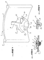
- FIG. 1 is a side view of a two components connecting the invention Befest onlysstopfens.
- FIG. 2 is a perspective view of a first embodiment of the fastening plug according to the invention.
- FIG. 3 is a plan view of the mounting plug of FIG. 1 ,
- FIG. 4 is a side view in the direction of arrow IV of FIG. 3 .
- FIG. 5 is a side view of another embodiment of a fastening plug according to the invention.
- FIG. 6 is a plan view of the mounting plug according to the FIG. 5 .
- FIG. 7 is a perspective view of another embodiment of the inventive attachment plug.
- FIG. 8 is a side view of the fastening plug of FIG. 7 , on a smaller scale.
- FIG. 9 is a side view of the inventive plug, which is at a right angle to the FIG. 8 is offset.
- FIG. 1 shows a fastening device according to the invention, with a fixing plug 1, which a sheet-like component 2, such as a sheet, a Dämmaterialteil or a mat, attached to a support member 3, which belongs for example to an automobile body.
- a fixing plug 1 which a sheet-like component 2, such as a sheet, a Dämmaterialteil or a mat, attached to a support member 3, which belongs for example to an automobile body.
- the fastening plug according to the invention has a flat, in the example rectangular rectangular slightly curved head 5, designed as a resting foot part 6, the through two aligned receiving holes 7, 8 inserted in the parts 2 and 3 and is locked behind the body part 3.
- the head part 1 and the Rastfußteil 6 are interconnected by a middle formed as a web 10 area.
- the head 1 is curved so that it can rest against the surface of the component 2 in the mounting position of the plug 1 with its beaded edges 12.
- the curvature has the task, thanks to the elastic deformation of the head after the insertion of the plug into the latching position to compensate for the resulting when engaging the body part 3 by the foot part game.
- the locking foot 6 has the shape of a pot with a circular bottom 15 and a non-essential cylindrical side wall, of which only two diametrically opposed segments 16 are present, each extending from a side edge of the web 10 substantially over a predetermined angle, between 45 ° and 135 °, for example, of 90 °.
- the side edge 19 of each segment 17 facing away from the web extends obliquely outwards from its starting point on the bottom 15.
- the upper facing towards the head area is bent outwards, so that a jagged latching wing 20 is formed, which is elastically deflected to the axes and the rear part of the carrier part rebounding outwardly when the Rastfußes through the holes 7, 8 in the two components Connecting plug behind the support part 3 locked.
- FIGS. 5 and 6 show a variant in which the free, resilient wings 20 extend substantially tangentially and have a length which is greater than that of the wings of the first embodiment.
- FIGS. 7 to 9 show an embodiment of the plug, in which the web 10 between the head 5 and the locking foot 6 has a diametrically extending rib 22, the dimensions transverse to the axis of the plug are slightly smaller than the diameter of the through holes 7, 8, so that the rib to Centering of the plug during insertion can serve.
- the additional rib starts only at a corresponding axial distance from the head.
- the curvature of the head 5 of the plug not only causes a balance of the game, which can be caused by the possibly existing axial component of the spring back of the locking wing behind the body part, but also a recording of possible thickness variations.
- axial Ausfederungskomplemente it should be noted that this is due to the substantially tangential alignment of the latching wings ideally no longer exists, since the wings slide after insertion along the lower surface of the body part.
- the fastening plugs according to the invention are preferably made of plastic.
- the twisted formed by the wings 20 latching form of the foot of the plug is for the rebound behind the hole of the support member a lower path tolerance compared to the known plug needed. Thanks to this shape, the assembly force is significantly reduced with the same disassembly force. A lateral load on the resting feet and the associated setting of the plastic, which in vibration leads to falling out of the known plug, is avoided.
Landscapes
- Engineering & Computer Science (AREA)
- General Engineering & Computer Science (AREA)
- Mechanical Engineering (AREA)
- Insertion Pins And Rivets (AREA)
- Connection Of Plates (AREA)
- Dowels (AREA)
- Cookers (AREA)
Description
- Die Erfindung betrifft eine Vorrichtung zur Befestigung von Bauteilen wie Blechen, Dämmaterialien oder Matten an Trägerteilen wie Automobilkarrosserien, mit einem Befestigungsstopfen, der ein Kopfteil, einen das Trägerteil hintergreifenden und einen durch Löcher im Bauteil und im Trägerteil durchsteckbaren Fußteil und einen den Kopf mit dem Fußteil verbindenden Mittelteil besitzt, vgl.
US-A-5 468 108 . - Die Befestigungsvorrichtungen dieser Art, die bekannt sind, besitzen den Nachteil, daß sie eine verhältnismässig große Montagekraft benötigen und die Montage sowie die Demontage verhältnismässig kompliziert sind.
- Der Erfindung liegt die Aufgabe zugrunde, eine Befestigungsvorrichtung zu schaffen, die diese Nachteile nicht besitzt.
- Zur Lösung dieser Aufgabe ist die erfindungsgemäße Vorrichtung u.a. dadurch charakterisiert, daß der Rastfuß beim Durchstecken elastisch zur Achse hin ausweichenden und nach dem Durchstecken wieder seine Orientierung einnimmt.
- Weitere Merkmale der Erfindung sind in Unteransprüchen beschrieben.
- Im folgenden wird die Erfindung unter Bezugnahme auf die abgebildenden Abbildungen näher beschrieben.
- Die
Figur 1 ist eine Seitenansicht eines zwei Bauteile miteinander verbindenden erfindungsgemäßen Befestigungsstopfens. - Die
Figur 2 ist eine perspektivische Ansicht einer ersten Ausführungsvariante des erfindungsgemäßen Befestigungsstopfens. - Die
Figur 3 ist eine Draufsicht auf dem Befestigungsstopfen derFigur 1 . - Die
Figur 4 ist eine Seitenansicht in Richtung des Pfeils IV derFigur 3 . - Die
Figur 5 ist eine Seitenansicht einer anderen Ausführungsvariante eines erfindungsgemäßen Befestigungsstopfens. - Die
Figur 6 ist eine Draufsicht auf den Befestigungsstopfen gemäß derFigur 5 . - Die
Figur 7 ist eine perspektivische Ansicht einer anderen Ausführungsform des erfindungsgemässen Befestigungsstopfens. - Die
Figur 8 ist eine Seitenansicht des Befestigungsstopfens derFigur 7 , in verkleinertem Maßstab. - Die
Figur 9 ist eine Seitenansicht des erfindungsgemässen Stopfens, die um einen rechten Winkel gegenüber derFigur 8 versetzt ist. - Die
Figur 1 zeigt eine erfindungsgemäße Befestigungsvorrichtung, mit einem Befestigungsstopfen 1, der ein flächiges Bauteil 2, wie ein Blech, ein Dämmaterialteil oder eine Matte, an einem Trägerteil 3, das z.B. zu einer Automobilkarrosserie gehört, befestigt. - Der erfindungsgemäße Befestigungsstopfen besitzt einen flächigen, im Beispielfall rechteckigen leicht gewölbten Kopf 5, einen als Rastfuß ausgebildeten Fußteil 6, der durch zwei miteinander fluchtende Aufnahmelöcher 7, 8 in den Teilen 2 und 3 hindurchgesteckt und hinter dem Karrosserieteil 3 verrastet ist. Der Kopfteil 1 und der Rastfußteil 6 sind miteinander durch einen mittleren als Steg 10 ausgebildeten Bereich miteinander verbunden. Wie insbesondere aus der
Figur 1 hervorgeht, ist der Kopf 1 gewölbt, damit er in der Befestigungsstellung des Stopfes 1 mit seinen wulstigen Rändern 12 an der Oberfläche des Bauteiles 2 angepreßt anliegen kann. Die Wölbung hat die Aufgabe, dank der elastischen Verformung des Kopfes nach dem Durchstecken des Stopfens in die Verraststellung das beim Hintergreifen des Karrosserieteils 3 durch das Fußteil entstehende Spiel zu kompensieren. - Der Rastfuß 6 besitzt die Form eines Topfes mit einem kreisförmigen Boden 15 und einer unwesentlichen zylindrischen Seitenwand, von der lediglich zwei einander diametral gegenüberliegenden Segmente 16 vorhanden sind, die sich jeweils von einem Seitenrand des Stegs 10 im wesentlichen über einen vorbestimmten Winkel, zwischen 45° und 135°, zum Beispiel von 90°, erstrecken. Der vom Steg abgewandte Seitenrand 19 jedes Segments 17 verläuft von seinem Ausgangspunkt am Boden 15 schräg nach aussen. Der obere zum Kopf hin gewandte Bereich ist nach aussen abgebogen, sodaß ein zackenförmige Rastflügel 20 entsteht, der bei einem Durchstecken des Rastfußes durch die Löcher 7, 8 in dem zwei Bauteilen elastisch zur Achsen auslenkbar ist und hinter dem Trägerteil wieder nach aussen ausfedert und den Verbindungsstopfen hinter dem Trägerteil 3 verrastet.
- Die
Figuren 5 und 6 zeigen eine Ausführungsvariante, bei der die freien, federnden Flügel 20 sich im wesentlichen tangential erstrecken und eine Länge haben, die grösser ist als die der Flügel der ersten Ausführungsvariante. - Die
Figuren 7 bis 9 zeigen eine Ausführungsform des Stopfens, bei der der Steg 10 zwischen dem Kopf 5 und dem Rastfuß 6 eine sich diametral erstreckende Rippe 22 besitzt, deren Abmasse quer zur Achse des Stopfens etwas kleiner sind als der Durchmesser der Durchstecklöcher 7, 8, sodaß die Rippe zur Zentrierung des Stopfens beim Durchstecken dienen kann. Um die Wölbung des Kopfes, die die Aufgabe hat, durch ihre elastische Verformung infolge des Ausfederns der Rastflügel das nach dem Durchstecken entstehendes Spiel auszugleichen, nicht zu beeinträchtigen, beginnt die Zusatzrippe erst in einem entsprechenden axialen Abstand vom Kopf. - Die Wölbung des Kopfes 5 des Stopfens bewirkt nicht nur ein Ausgleich des Spiels, der durch die möglicherweise vorhandene axiale Komponente des Zurückfederns der Rastflügel hinter dem Karrosserieteil entstehen kann, sondern auch eine Aufnahme möglicher Dickenabweichungen. Bezüglich der axialen Ausfederungskomplemente ist zu bemerken, daß diese dank der im wesentlichen tangentialen Ausrichtung der Rastflügel im Idealfall nicht mehr vorhanden ist, da die Flügel nach dem Durchstecken entlang der Unterfläche des Karrosserieteils gleiten. Durch Versetzen der Anbindung der Flügel am Topf in Richtung zum Kopf hin, kann die gegebenenfalls noch vorhandene restliche axiale Rückfederungskomponente noch weiter verringert werden.
- Die erfindungsgemäßen Befestigungsstopfen sind vorzugsweise aus Kunststoff hergestellt. Durch die gedrehte von den Flügeln 20 gebildete Rastform des Fußes der Stopfen wird für das Ausfedern hinter dem Loch des Trägerteils eine geringere Weg-Toleranz im Vergleich zu den bekannten Stopfen, benötigt. Dank dieser Form wird die Montagekraft bei gleich bleibender Demontagekraft deutlich gesenkt. Eine seitliche Belastung auf die Rastfüße und das damit verbundene Setzen des Kunststoff, welches bei Vibrationen zu einem Herausfallen der bekannten Stopfen führt, wird vermieden.
Claims (11)
- Vorrichtung zur Befestigung von Bauteilen wie Blechen, Dämmaterialien oder Matten an Trägerteilen wie Automobilkarrosserien, mit einem Befestigungsstopfen, der ein Kopfteil, ein das Trägerteil hintergreifenden und durch Löcher im Bauteil und im Trägerteil durchsteckbaren, als hinter dem Trägerteil verrastbaren Rastfuß ausgebildeten Fußteil und ein den Kopf mit dem Trägerteil verbindenden Mittelteil besitzt, dadurch gekennzeichnet, daß der Rastfuß (6) wenigstens einen sich von einer im wesentlichen zylindrischen Gestalt nach aussen erstreckenden Rastflügel (20) besitzt, der beim Durchstecken durch die Löcher (7, 8) im Bauteil und im Trägerteil elastisch zur Achse hin ausweicht und nach dem Durchstecken wieder seine nach aussen gerichtete Orientierung zur Verrastung hinter dem Trägerteil einnimmt wobei der Rastfuß (6) von einer Topfform ausgehend ausgebildet ist und wenigstens ein aus der Seitenwand des Topfes ausgeschnittenes Segment (16) besitzt, das sich umfangsmässig über einen bestimmten Winkel erstreckt und daß wenigstens einer seiner freien Randbereiche als Rastflügel (20) ausgebildet ist.
- Vorrichtung nach Anspruch 1, dadurch gekennzeichnet, daß der Fußteil (6) des Befestigungsstopfens zwei einander diametral gegenüberliegende Rastflügel (20) besitzt.
- Vorrichtung nach Anspruch 1 oder 2, dadurch gekennzeichnet, daß der Boden (15) des Topfes am freien Ende eines Steges (10), der den Mittelteil bildet, angeformt ist.
- Vorrichtung nach Anspruch 3, dadurch gekennzeichnet, daß der Steg (10) eine Breite besitzt, die gleich dem Durchmesser des Topfbodens (15) ist und daß ein Segment (16) sich von dem Steg aus in Umfangsrichtung um den genannten vorgenannten Winkel erstreckt.
- Vorrichtung nach Anspruch 4, dadurch gekennzeichnet, daß der freie Seitenrand (19) eines Segments (16) bezogen auf eine radiale Ebene geneigt ist, sodaß der freie Umfangsrand des Segments länger ist als der Umfangsrand im Bereich des Topfbodens (15) und daß der freie Endbereich des Segments den genannten Rastflügel (20) bildet.
- Vorrichtung nach Anspruch 5, dadurch gekennzeichnet, daß der Rastflügel durch seitliches Ausformen des freien Endes des Segments entstanden ist.
- Vorrichtung nach Anspruch 5, dadurch gekennzeichnet, daß der Rastflügel sich tangential erstreckt.
- Vorrichtung nach einem der Ansprüche 1 bis 7, dadurch gekennzeichnet, daß der Umfangswinkel des Segments in der Größenordnung von 45° bis 135°, vorzugsweise von 90° liegt.
- Vorrichtung nach einem der Ansprüche 1 bis 8, dadurch gekennzeichnet, daß der Befestigungsstopfen am Kunstoff besteht.
- Vorrichtung nach einem der Ansprüche 1 bis 8, dadurch gekennzeichnet, daß der Befestigungsstopfen zwischen seinem Kopf (5) und seinem Rastfuß (6) einen Zentrieransatz (22) besitzt.
- Vorrichtung nach einem der Ansprüche 1 bis 10, dadurch gekennzeichnet, daß der Montagewinkel der Rastflügel zur Lochkante flach ist, sodaß ein hoher Toleranzausgleich Bohrung-Federweg erhältlich ist.
Priority Applications (3)
| Application Number | Priority Date | Filing Date | Title |
|---|---|---|---|
| ES06291306T ES2334816T3 (es) | 2006-08-11 | 2006-08-11 | Dispositivo para la fijacion de componentes a una pieza soporte. |
| DE200650005117 DE502006005117D1 (de) | 2006-08-11 | 2006-08-11 | Vorrichtung zur befestigung von bauteilen an einem tragerteil |
| EP20060291306 EP1887231B1 (de) | 2006-08-11 | 2006-08-11 | Vorrichtung zur befestigung von bauteilen an einem tragerteil |
Applications Claiming Priority (1)
| Application Number | Priority Date | Filing Date | Title |
|---|---|---|---|
| EP20060291306 EP1887231B1 (de) | 2006-08-11 | 2006-08-11 | Vorrichtung zur befestigung von bauteilen an einem tragerteil |
Publications (2)
| Publication Number | Publication Date |
|---|---|
| EP1887231A1 EP1887231A1 (de) | 2008-02-13 |
| EP1887231B1 true EP1887231B1 (de) | 2009-10-14 |
Family
ID=37594928
Family Applications (1)
| Application Number | Title | Priority Date | Filing Date |
|---|---|---|---|
| EP20060291306 Not-in-force EP1887231B1 (de) | 2006-08-11 | 2006-08-11 | Vorrichtung zur befestigung von bauteilen an einem tragerteil |
Country Status (3)
| Country | Link |
|---|---|
| EP (1) | EP1887231B1 (de) |
| DE (1) | DE502006005117D1 (de) |
| ES (1) | ES2334816T3 (de) |
Families Citing this family (2)
| Publication number | Priority date | Publication date | Assignee | Title |
|---|---|---|---|---|
| GB0909984D0 (en) | 2009-06-11 | 2009-07-22 | Rolls Royce Plc | Fastener |
| AT12447U8 (de) * | 2010-11-04 | 2012-08-15 | Schnabl Stecktechnik Gmbh | Verfahren und befestigungselement zum festlegen eines elements an einer aufnahme sowie system hierzu |
Family Cites Families (2)
| Publication number | Priority date | Publication date | Assignee | Title |
|---|---|---|---|---|
| US5468108A (en) * | 1994-09-12 | 1995-11-21 | Illinois Tool Works Inc. | Spiral flex tree fastener |
| DE19651784C1 (de) * | 1996-12-12 | 1998-08-06 | United Carr Gmbh Trw | Halteelement aus Kunststoff |
-
2006
- 2006-08-11 ES ES06291306T patent/ES2334816T3/es active Active
- 2006-08-11 DE DE200650005117 patent/DE502006005117D1/de active Active
- 2006-08-11 EP EP20060291306 patent/EP1887231B1/de not_active Not-in-force
Also Published As
| Publication number | Publication date |
|---|---|
| DE502006005117D1 (de) | 2009-11-26 |
| EP1887231A1 (de) | 2008-02-13 |
| ES2334816T3 (es) | 2010-03-16 |
Similar Documents
| Publication | Publication Date | Title |
|---|---|---|
| EP0954459B1 (de) | Befestigungselement | |
| EP2793649B1 (de) | Schwingungsgedämpftes möbel in der form eines tisches | |
| EP3077684B1 (de) | Ringförmige steckkupplung sowie ein herstellungs- und ein verbindungsverfahren dafür | |
| DE19830752A1 (de) | Befestigungsclip | |
| EP2838766B1 (de) | Wischblattvorrichtung | |
| DE19958745C1 (de) | Befestigungseinrichtung mit Federsicherung für einen Sicherheitsgurtbeschlag | |
| DE102013226182A1 (de) | Anordnung zur Befestigung eines Innenverkleidungsteils an einer Fahrzeugkarosserie | |
| EP0526782B1 (de) | Plastik-Clip zur Blindbefestigung von weichelastischen Flachkörpern auf Trägerplatten | |
| DE102019211673A1 (de) | Befestigungselement für ein Gehäuse zum Befestigen des Gehäuses an einer Trägerstruktur und Montagesystem | |
| EP2980425B1 (de) | Befestigungsanordnung für c-förmige halteschienen und bausatz | |
| DE102017114301A1 (de) | Schwingungstilgerring sowie gassackmodul mit einem solchen schwingungstilgerring | |
| WO2016087141A1 (de) | Vorrichtung zum halten einer systemkomponente an einem anschlussteil eines fahrzeugs | |
| EP1963689B1 (de) | Blechmutter | |
| DE10210628C1 (de) | Vorrichtung zur spielfreien Ein-Mann Montage eines Anbauteils, oder einer Kfz-Dachantenne | |
| DE102007015129B3 (de) | Nicht demontierbarer Clip aus Kunststoff | |
| EP2588766B1 (de) | Befestigungseinrichtung | |
| DE102012101179A1 (de) | Clip und Befestigungsanordnung mit einem Clip | |
| EP1887231A1 (de) | Vorrichtung zur befestigung von bauteilen an einem tragerteil | |
| EP1480306A2 (de) | Befestigungshülse zur Befestigung eines Sensorgehäuses | |
| EP2300677B1 (de) | Scharniertopf für möbelscharniere | |
| DE202009002003U1 (de) | Beschlag und Wandschrank | |
| EP3419849B1 (de) | Haltevorrichtung für eine auspuffanlage | |
| EP0794087A2 (de) | Aussenrückblickspiegel für Fahrzeuge, vorzugsweise für Kraftfahrzeuge | |
| DE202005019612U1 (de) | Vorrichtung zur lösbaren Befestigung eines flachen Bauteils an einer Trägerstruktur | |
| DE602004005534T2 (de) | Elastisches Befestigungselement mit einer Verdrehsicherung |
Legal Events
| Date | Code | Title | Description |
|---|---|---|---|
| PUAI | Public reference made under article 153(3) epc to a published international application that has entered the european phase |
Free format text: ORIGINAL CODE: 0009012 |
|
| AK | Designated contracting states |
Kind code of ref document: A1 Designated state(s): AT BE BG CH CY CZ DE DK EE ES FI FR GB GR HU IE IS IT LI LT LU LV MC NL PL PT RO SE SI SK TR |
|
| AX | Request for extension of the european patent |
Extension state: AL BA HR MK YU |
|
| 17P | Request for examination filed |
Effective date: 20080730 |
|
| 17Q | First examination report despatched |
Effective date: 20080904 |
|
| AKX | Designation fees paid |
Designated state(s): DE ES FR GB IT |
|
| GRAP | Despatch of communication of intention to grant a patent |
Free format text: ORIGINAL CODE: EPIDOSNIGR1 |
|
| GRAS | Grant fee paid |
Free format text: ORIGINAL CODE: EPIDOSNIGR3 |
|
| GRAA | (expected) grant |
Free format text: ORIGINAL CODE: 0009210 |
|
| AK | Designated contracting states |
Kind code of ref document: B1 Designated state(s): DE ES FR GB IT |
|
| REG | Reference to a national code |
Ref country code: GB Ref legal event code: FG4D Free format text: NOT ENGLISH |
|
| REF | Corresponds to: |
Ref document number: 502006005117 Country of ref document: DE Date of ref document: 20091126 Kind code of ref document: P |
|
| REG | Reference to a national code |
Ref country code: ES Ref legal event code: FG2A Ref document number: 2334816 Country of ref document: ES Kind code of ref document: T3 |
|
| PLBE | No opposition filed within time limit |
Free format text: ORIGINAL CODE: 0009261 |
|
| STAA | Information on the status of an ep patent application or granted ep patent |
Free format text: STATUS: NO OPPOSITION FILED WITHIN TIME LIMIT |
|
| 26N | No opposition filed |
Effective date: 20100715 |
|
| PGFP | Annual fee paid to national office [announced via postgrant information from national office to epo] |
Ref country code: GB Payment date: 20120831 Year of fee payment: 7 |
|
| PGFP | Annual fee paid to national office [announced via postgrant information from national office to epo] |
Ref country code: IT Payment date: 20120823 Year of fee payment: 7 |
|
| PGFP | Annual fee paid to national office [announced via postgrant information from national office to epo] |
Ref country code: ES Payment date: 20120928 Year of fee payment: 7 |
|
| GBPC | Gb: european patent ceased through non-payment of renewal fee |
Effective date: 20130811 |
|
| PG25 | Lapsed in a contracting state [announced via postgrant information from national office to epo] |
Ref country code: IT Free format text: LAPSE BECAUSE OF NON-PAYMENT OF DUE FEES Effective date: 20130811 |
|
| PG25 | Lapsed in a contracting state [announced via postgrant information from national office to epo] |
Ref country code: GB Free format text: LAPSE BECAUSE OF NON-PAYMENT OF DUE FEES Effective date: 20130811 |
|
| PG25 | Lapsed in a contracting state [announced via postgrant information from national office to epo] |
Ref country code: ES Free format text: LAPSE BECAUSE OF NON-PAYMENT OF DUE FEES Effective date: 20130812 |
|
| PGFP | Annual fee paid to national office [announced via postgrant information from national office to epo] |
Ref country code: FR Payment date: 20140827 Year of fee payment: 9 |
|
| PGFP | Annual fee paid to national office [announced via postgrant information from national office to epo] |
Ref country code: DE Payment date: 20141031 Year of fee payment: 9 |
|
| REG | Reference to a national code |
Ref country code: DE Ref legal event code: R119 Ref document number: 502006005117 Country of ref document: DE |
|
| REG | Reference to a national code |
Ref country code: FR Ref legal event code: ST Effective date: 20160429 |
|
| PG25 | Lapsed in a contracting state [announced via postgrant information from national office to epo] |
Ref country code: DE Free format text: LAPSE BECAUSE OF NON-PAYMENT OF DUE FEES Effective date: 20160301 |
|
| PG25 | Lapsed in a contracting state [announced via postgrant information from national office to epo] |
Ref country code: FR Free format text: LAPSE BECAUSE OF NON-PAYMENT OF DUE FEES Effective date: 20150831 |