EP1887151A2 - Articulation fitting - Google Patents
Articulation fitting Download PDFInfo
- Publication number
- EP1887151A2 EP1887151A2 EP07015046A EP07015046A EP1887151A2 EP 1887151 A2 EP1887151 A2 EP 1887151A2 EP 07015046 A EP07015046 A EP 07015046A EP 07015046 A EP07015046 A EP 07015046A EP 1887151 A2 EP1887151 A2 EP 1887151A2
- Authority
- EP
- European Patent Office
- Prior art keywords
- condyle
- support according
- articulated support
- articulated
- bearing
- Prior art date
- Legal status (The legal status is an assumption and is not a legal conclusion. Google has not performed a legal analysis and makes no representation as to the accuracy of the status listed.)
- Granted
Links
- 238000011161 development Methods 0.000 description 10
- 230000018109 developmental process Effects 0.000 description 10
- 241000309551 Arthraxon hispidus Species 0.000 description 5
- 230000015572 biosynthetic process Effects 0.000 description 2
- 230000001419 dependent effect Effects 0.000 description 1
- 230000000694 effects Effects 0.000 description 1
- 210000003746 feather Anatomy 0.000 description 1
Images

Classifications
-
- E—FIXED CONSTRUCTIONS
- E03—WATER SUPPLY; SEWERAGE
- E03C—DOMESTIC PLUMBING INSTALLATIONS FOR FRESH WATER OR WASTE WATER; SINKS
- E03C1/00—Domestic plumbing installations for fresh water or waste water; Sinks
- E03C1/02—Plumbing installations for fresh water
- E03C1/06—Devices for suspending or supporting the supply pipe or supply hose of a shower-bath
Definitions
- the invention relates to a holder, as is to be used in particular for sanitary articles.
- Sanitary articles have the general problem that they should be installed in a certain orientation.
- a sanitary element is to assume a hand shower, which is inserted, for example, at the end of its handle in a holder. It should then be able to be adjusted in different directions.
- Such a hinge bracket must meet a variety of requirements.
- it should be space-saving and disturb as little as possible.
- certain positions should not be taken, as it makes little sense to judge a hand shower, for example, against the ceiling.
- a ball head is attached to a wall bar slider, on which the actual cone holder is supported pivotably. With the help of a union nut, this cone holder is more or less firmly pressed against the ball head, thereby adjusting the ease and the lock can.
- an adjustable shower wall hanger ( DE 195 09 138 ), in which at the end of an articulated arm, a ball head with a flattened position is present, against which a spring-loaded piston presses. As a result, a determination in a certain position is preferred from which the articulated arm can also be moved out, in all directions.
- the invention is based on the object to provide a hinge bracket, which is particularly adapted to the requirements of a sanitary fitting and can be used for it.
- the invention proposes a joint mount with the features mentioned in claim 1. Further developments of the invention are the subject of dependent claims.
- the holder thus contains a storage, which can be changed in its position relative to the sanitary element, if it is connected to the holder.
- the joint head In storage, the joint head is mounted, which has a rotationally symmetrical lateral surface, in particular also a rotationally symmetrical surface.
- the axis of rotation of the rotationally symmetrical lateral surface of the condyle then forms the axis about which the articulated arm can be pivoted.
- the storage takes place between the lateral surface of the condyle and the surrounding bearing surface of the bearing shell on which abuts the lateral surface.
- the condyle has the shape of a disc.
- the rotationally symmetric surface is then limited by two at least approximately parallel planar or at least approximately planar surfaces. This leads to, that the space required for the storage remains small, even when the rotationally symmetric surface has a relatively large diameter.
- the bearing shell has the shape of a disc, that is bounded by two at least approximately parallel planar or at least approximately planar surfaces.
- this lateral surface is a cylindrical surface.
- the articulated arm can be pivoted about an axis fixed relative to the storage. This may be sufficient in simple cases for a sanitary fitting.
- the lateral surface may also differ from a cylindrical surface.
- the lateral surface of the condyle and / or the bearing surface of the bearing shell lies in a spherical surface, and in particular the condyle is a spherical disc.
- the thickness of the disc need not be the same for both parts.
- the bearing has a pivoting angle limitation, which preferably inside the condyle. Since the condyle is usually visible from the outside in the vicinity of the articulated arm, a swivel angle limit which acts on the outside would lead to traces becoming visible during use. When attacking the swivel angle limiting on the inside of the condyle, that is below the surface of rotation, no visible from the outside wear marks. Therefore, this type of training is particularly suitable for sanitary brackets, where attention is paid to a visually appealing training.
- the bearing for the joint head forms an axis which is perpendicular to the axis of rotation of the surface of the bearing shell.
- This means that the articulated arm receives a second degree of freedom of pivoting.
- a rotation about an axis running perpendicular thereto can now also be made possible.
- this axis is formed by a shaft which passes through the condyle and in particular cuts the axis of rotation of the condyle.
- the shaft may, for example, be a rod which is fixed in the bearing at at least one of its ends.
- the axis is formed by one or two stub shafts, which are thus formed as separate axially aligned elements.
- An example of a shaft may be a screw which is inserted through the condyle and bolted to the bearing.
- the screw is screwed into a nut, with whose help the shaft can be clamped.
- the invention proposes, in a further development of the shaft in such a way that it passes through an opening of the condyle.
- the opening can be configured in a development of the invention so that it corresponds to the diameter of the shaft at the narrowest point.
- an article having a circular cross section is preferably used as the shaft.
- the opening is formed as a slot with a constant width, said width corresponds to the previously said the diameter of the shaft.
- the slot diverges transversely to its width starting from the axis of rotation, and in particular has a wedge shape. This makes it possible that the articulated arm can be pivoted about the axis of rotation about the angle determined by the wedge angle. So this forms an example of the mentioned pivoting angle limit, which acts in the interior of the condyle.
- the opening of the condyle is spatially diverging from the axis of rotation, so that a conical shape can be present. This makes the movement around two axes possible to a limited extent.
- the bearing has a biasing means for the bearing shell. This is to ensure that the hinge bracket can be adjusted so that when no external forces acting on them, the sanitary element remains in position. On the other hand, it should also be easy to pivot.
- This biasing means may be an additional element acting outside the condyle. It is particularly useful, however, if the shaft passing through the joint head, which defines an axis, is at the same time also designed as a biasing means.
- a spring loading is provided as a biasing means, which can be solved for example by a push button. In this case, a fixed deadlock can be performed.
- the articulated arm is preferably arranged so that it protrudes from the rotationally symmetrical surface of the condyle, that is not attached laterally.
- the storage has a cover that covers the joint head and the bearing shell on all sides, so that only one of the articulated arm passing let opening remains that must of course be sized so large that the articulated arm is also in the intended manner to move.
- the hinge mount which is provided by the invention, may for example be arranged on a slider of a wall bar, or may be formed as fixed to a wall or other element mounted storage.
- Figure 1 is broken off the side view of a wall bar 1 shown, which is designed as a profile and can be attached either directly or at a distance in front of a wall.
- the wall rod 1 along a slider 2 can be moved, which is supported with rollers 3 or sliding blocks on the profile and stops in any position. Details of the slider 2 are not shown, since they are known per se.
- the bearing 4 contains in the slider 2, a bearing shell 6, which is integrally formed and in its central region has an opening 7, the surface 17 is a surface of revolution having a circular cross-section. The circle extends over about 3/4 of a circular arc.
- the bearing shell surface 17 of the bearing shell 6 and the rotation surface 9 of the condyle 8 naturally have a common axis of rotation which simultaneously forms the axis of rotation about which the condyle 8 and thus the articulated arm 5 can be rotated.
- the condyle 8 also has an opening 11, the longitudinal axis of which is offset from the point of attachment of the articulated arm 5 in the sectional plane of FIG. 1 by approximately 90 °.
- the opening 11 has a narrowest point 12, which lies in the middle between the two outer ends of the opening 11.
- the screw 12 corresponds to the width and the thickness of the opening 11 the diameter of a screw 12 which is inserted through the bore 10 and the opening 11 therethrough.
- the screw 12 includes a screw head 13, on the other hand, the screw 12 is screwed into a nut 14, to the rotation of a drive recess 15 is provided which points away from the screw 12.
- the aperture 11 diverges in a shape corresponding to a wedge.
- the side walls 16 of the aperture 11 thus extend in a straight line.
- the condyle 8 and with him the articulated arm 5 can be pivoted clockwise until the side wall 16 of the aperture 12 comes to rest on the shank of the screw.
- the aperture 11 is formed symmetrically on both sides of the narrowest point 12, then the side walls 16 are above and below the middle part of the shaft of the screw 12 at. This concern forms a limitation of the angle of rotation by which the articulated arm 5 can be pivoted.
- FIG. 1 likewise shows that a housing in the form of a cover 18 is present around the bearing shell 6, covering the entire bearing shell with the exception of an opening 19.
- the opening 19 is required so that the articulated arm 5 has sufficient space for its pivoting.
- the cover 18 In extension of the drive recess 15 of the nut 14, the cover 18 has an opening 20, can be intervened by the with a tool in the screw drive recess 15.
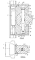
- FIG. 2 shows a cross section through the arrangement of FIG. 1 below the narrowest point 12 of the condyle 8.
- both the bearing surface 17 of the bearing shell 6 and the voltage applied to her rotation surface 9 of the condyle 8 are part of a spherical surface.
- the condyle 9 can therefore not only be perpendicular to the plane of the drawing of FIG extending axis of rotation to be pivoted, but also about an axis perpendicular to the paper plane of Figure 2 extending axis, which coincides in this case with the longitudinal axis of the screw 12.
- the width of the aperture 11 forming slot measured in Figure 2 from top to bottom, corresponds approximately to the outer diameter of the screw 12.
- the condyle 8 can be pivoted about the screw 12 around, so in addition to the pivoting about a vertical to the screw 12 extending axis.
- the shaft 12 prevents the condyle 8 can be rotated about an axis extending from left to right in Figure 2. But this could also be achieved if the aperture 11 diverges not only in the sectional plane of Figure 1, but also in the sectional plane of Figure 2, so instead of a double wedge a double cone would be formed.
- the screw 12 which is shown in Figure 1, here has a triple function. On the one hand, it forms the axis about which a pivoting of the articulated arm 5 can take place. Moreover, it forms, together with the side walls 16 of the opening 11, a pivoting angle limitation during pivoting in the sectional plane of FIG. 1.
- the third object is to effect the tensioning of the two arms 6 a, 6 b of the bearing shell 6.
- the tension of the two arms 6 a, 6 b of the bearing shell 6 could also take place on both sides of the condyle 8.
- the rotation angle limit and the rotation axis formation could also be done by each arm 6 a, 6 b would project a pin into the opening 11, without the two pins would be connected to each other.
- the condyle 8 is not designed as a full ball but as a spherical disc with two parallel ones Outer surfaces 21.
- the bearing shell 6 is formed as a disc member with parallel side surfaces, which coincide in the illustration of Figure 2 with the side surfaces 21 of the condyle 8.
- Figure 3 shows in a smaller detail the arrangement of the slider 2 with the bearing contained in it on a wall rod, which protrudes from the wall bar 1 facing away from the front side 22 of the cover 18 of the articulated arm 5.
- a cone holder 23 is arranged for the handle of a hand shower.
Abstract
Description
Die Erfindung betrifft einer Halterung, wie insbesondere für Sanitärgegenstände verwendet werden soll. Bei Sanitärgegenständen besteht das allgemeine Problem, dass diese in einer bestimmten Ausrichtung angebracht werden sollen. Als Beispiel für ein derartiges Sanitärelement ist eine Handbrause anzunehmen, die beispielsweise am Ende ihres Griffs in einer Halterung eingesteckt wird. Sie soll dann in unterschiedliche Richtungen verstellt werden können. Eine solche Gelenkhalterung muss die unterschiedlichsten Forderungen erfüllen. Zum einen soll sie leicht verstellbar sein, zum anderen soll sie aber auch so ausgebildet sein, dass sie sich nicht von selbst verstellt. Außerdem soll sie Platz sparend sein und möglichst wenig stören. Weiterhin sollen bestimmte Positionen nicht eingenommen werden können, da es wenig Sinn macht, eine Handbrause beispielsweise gegen die Decke zu richten.The invention relates to a holder, as is to be used in particular for sanitary articles. Sanitary articles have the general problem that they should be installed in a certain orientation. As an example of such a sanitary element is to assume a hand shower, which is inserted, for example, at the end of its handle in a holder. It should then be able to be adjusted in different directions. Such a hinge bracket must meet a variety of requirements. On the one hand, it should be easy to adjust, on the other hand, it should also be designed so that it does not move by itself. In addition, it should be space-saving and disturb as little as possible. Furthermore, certain positions should not be taken, as it makes little sense to judge a hand shower, for example, against the ceiling.
Bei einer bekannten Haltevorrichtung für einen Brausekopf (
Ebenfalls bekannt ist eine einstellbare Duschen-Wandaufhängung (
Der Erfindung liegt die Aufgabe zu Grunde, eine Gelenkhalterung zu schaffen, die insbesondere an die Anforderungen einer Sanitärhalterung angepasst ist und dafür verwendet werden kann.The invention is based on the object to provide a hinge bracket, which is particularly adapted to the requirements of a sanitary fitting and can be used for it.
Zur Lösung dieser Aufgabe schlägt die Erfindung eine Gelenkhalterung mit den im Anspruch 1 genannten Merkmalen vor. Weiterbildungen der Erfindung sind Gegenstand von Unteransprüchen.To solve this problem, the invention proposes a joint mount with the features mentioned in
Die Halterung enthält also eine Lagerung, der gegenüber das Sanitärelement, sofern es mit der Halterung verbunden ist, in seiner Lage verändert werden kann. In der Lagerung ist der Gelenkkopf gelagert, der eine rotationssymmetrische Mantelfläche, insbesondere auch eine rotationssymmetrische Oberfläche aufweist. Die Rotationsachse der rotationssymmetrischen Mantelfläche des Gelenkkopfs bildet dann die Achse, um die der Gelenkarm verschwenkt werden kann. Die Lagerung geschieht zwischen der Mantelfläche des Gelenkkopfs und der diese umgebenden Lagerfläche der Lagerschale, an der die Mantelfläche anliegt.The holder thus contains a storage, which can be changed in its position relative to the sanitary element, if it is connected to the holder. In storage, the joint head is mounted, which has a rotationally symmetrical lateral surface, in particular also a rotationally symmetrical surface. The axis of rotation of the rotationally symmetrical lateral surface of the condyle then forms the axis about which the articulated arm can be pivoted. The storage takes place between the lateral surface of the condyle and the surrounding bearing surface of the bearing shell on which abuts the lateral surface.
In Weiterbildung der Erfindung kann vorgesehen sein, dass der Gelenkkopf die Form einer Scheibe aufweist. Die rotationssymmetrische Oberfläche ist also dann von zwei mindestens angenähert parallelen ebenen oder mindestens angenähert ebenen Flächen begrenzt. Dies führt dazu, dass der Platzbedarf für die Lagerung selbst dann, wenn die rotationssymmetrische Oberfläche einen relativ großen Durchmesser aufweist, klein bleibt.In a further development of the invention can be provided that the condyle has the shape of a disc. The rotationally symmetric surface is then limited by two at least approximately parallel planar or at least approximately planar surfaces. This leads to, that the space required for the storage remains small, even when the rotationally symmetric surface has a relatively large diameter.
Erfindungsgemäß kann ebenfalls zusätzlich oder alternativ vorgesehen sein, dass auch die Lagerschale die Form einer Scheibe aufweist, also von zwei mindestens angenähert parallelen ebenen oder mindestens angenähert ebenen Flächen begrenzt wird.According to the invention can also be provided additionally or alternatively, that the bearing shell has the shape of a disc, that is bounded by two at least approximately parallel planar or at least approximately planar surfaces.
Eine im Rahmen der Erfindung liegende Möglichkeit, wie die rotationssymmetrische Mantelfläche ausgebildet sein kann, besteht darin, dass diese Mantelfläche eine Zylinderfläche ist. Dies bedeutet, dass der Gelenkarm um eine gegenüber der Lagerung ortsfeste Achse verschwenkt werden kann. Dies kann in einfachen Fällen für eine Sanitärhalterung durchaus ausreichen. Bei einer Verschwenkung um nur eine Achse kann die Mantelfläche auch von einer Zylinderfläche abweichen.A possibility, which is within the scope of the invention, of how the rotationally symmetrical lateral surface can be formed consists in that this lateral surface is a cylindrical surface. This means that the articulated arm can be pivoted about an axis fixed relative to the storage. This may be sufficient in simple cases for a sanitary fitting. When pivoting about only one axis, the lateral surface may also differ from a cylindrical surface.
In Weiterbildung der Erfindung kann aber auch vorgesehen sein, dass die Mantelfläche des Gelenkkopfs und/oder die Lagerfläche der Lagerschale in einer Kugeloberfläche liegt, und insbesondere der Gelenkkopf eine Kugelscheibe ist.In a further development of the invention can also be provided that the lateral surface of the condyle and / or the bearing surface of the bearing shell lies in a spherical surface, and in particular the condyle is a spherical disc.
Bei einer Ausbildung der Lagerschale und/oder des Gelenkkopfs als Scheibe braucht die Dicke der Scheibe bei beiden Teilen nicht gleich zu sein.In an embodiment of the bearing shell and / or the condyle as a disc, the thickness of the disc need not be the same for both parts.
Bei der Ausbildung der Rotationsoberfläche als Zylinderfläche ist bereits dafür gesorgt, dass nur eine bestimmte Bewegung in einer bestimmten Ebene auftreten kann. Es wurde ja eingangs erwähnt, dass es in bestimmten Fällen sinnvoll ist, die Bewegung in gewisser Weise einzuschränken. Hierzu kann erfindungsgemäß auch vorgesehen sein, dass die Lagerung eine Schwenkwinkelbegrenzung aufweist, die vorzugsweise im Inneren des Gelenkkopfs angreift. Da der Gelenkkopf in der Regel in der Nähe des Gelenkarms von außen sichtbar ist, würde eine Schwenkwinkelbegrenzung, die an der Außenseite angreift, zu bei der Benutzung sichtbar werdenden Spuren führen. Beim Angreifen der Schwenkwinkelbegrenzung an der Innenseite des Gelenkkopfs, das heißt unterhalb der Rotationsoberfläche, treten keine von außen sichtbaren Abnutzungsspuren auf. Daher eignet sich diese Art der Ausbildung besonders bei Sanitärhalterungen, wo auf eine optisch ansprechende Ausbildung besonders geachtet wird.In the formation of the rotation surface as a cylindrical surface is already ensured that only a certain movement can occur in a particular plane. It was mentioned at the beginning that in certain cases it makes sense to limit the movement in a certain way. For this purpose, it can also be provided according to the invention that the bearing has a pivoting angle limitation, which preferably inside the condyle. Since the condyle is usually visible from the outside in the vicinity of the articulated arm, a swivel angle limit which acts on the outside would lead to traces becoming visible during use. When attacking the swivel angle limiting on the inside of the condyle, that is below the surface of rotation, no visible from the outside wear marks. Therefore, this type of training is particularly suitable for sanitary brackets, where attention is paid to a visually appealing training.
In Weiterbildung der Erfindung kann vorgesehen sein, dass die Lagerung für den Gelenkkopf eine Achse bildet, die senkrecht zu der Rotationsachse der Oberfläche der Lagerschale verläuft. Dies bedeutet, dass der Gelenkarm einen zweiten Freiheitsgrad der Verschwenkung erhält. Zusätzlich zu der Verschwenkung um die Rotationsachse kann jetzt auch noch eine Verdrehung um eine senkrecht hierzu verlaufende Achse ermöglicht werden.In a further development of the invention can be provided that the bearing for the joint head forms an axis which is perpendicular to the axis of rotation of the surface of the bearing shell. This means that the articulated arm receives a second degree of freedom of pivoting. In addition to the pivoting about the axis of rotation, a rotation about an axis running perpendicular thereto can now also be made possible.
Insbesondere kann hier vorgesehen sein, dass diese Achse von einer Welle gebildet ist, die durch den Gelenkkopf hindurch geht und insbesondere die Rotationsachse des Gelenkkopfs schneidet.In particular, it may be provided here that this axis is formed by a shaft which passes through the condyle and in particular cuts the axis of rotation of the condyle.
Bei der Welle kann es sich beispielsweise um einen Stab handeln, der in der Lagerung an mindestens einem seiner Enden festgelegt ist.The shaft may, for example, be a rod which is fixed in the bearing at at least one of its ends.
Es kann erfindungsgemäß aber auch vorgesehen sein, dass die Achse von einem oder zwei Wellenstümpfen gebildet wird, die also als getrennte axial ausgerichtete Elemente ausgebildet sind.However, it can also be provided according to the invention that the axis is formed by one or two stub shafts, which are thus formed as separate axially aligned elements.
Ein Beispiel für eine Welle, wie es die Erfindung vorschlägt, kann eine Schraube sein, die durch den Gelenkkopf hindurch gesteckt und mit der Lagerung verschraubt ist.An example of a shaft, as the invention suggests, may be a screw which is inserted through the condyle and bolted to the bearing.
Es kann erfindungsgemäß ebenfalls vorgesehen sein, dass die Schraube in eine Mutter eingeschraubt ist, mit dem deren Hilfe die Welle verspannt werden kann.It may also be provided according to the invention that the screw is screwed into a nut, with whose help the shaft can be clamped.
Insbesondere schlägt die Erfindung vor, in Weiterbildung die Welle so auszugestalten, dass sie durch eine Durchbrechung des Gelenkkopfs hindurch geht.In particular, the invention proposes, in a further development of the shaft in such a way that it passes through an opening of the condyle.
Die Durchbrechung kann in Weiterbildung der Erfindung so ausgestaltet sein, dass sie an der engsten Stelle dem Durchmesser der Welle entspricht. Als Welle wird vorzugsweise ein Gegenstand mit einem kreisrunden Querschnitt verwendet.The opening can be configured in a development of the invention so that it corresponds to the diameter of the shaft at the narrowest point. As the shaft, an article having a circular cross section is preferably used.
In nochmaliger Weiterbildung der Erfindung kann vorgesehen sein, dass die Durchbrechung als Schlitz mit einer konstanten Breite ausgebildet ist, wobei diese Breite entsprechend dem vorher gesagten dem Durchmesser der Welle entspricht. Auf diese Weise kann dafür gesorgt werden, dass eine Bewegung des Gelenkarms um zwei zueinander senkrecht stehende Achsen möglich ist, dass aber eine dritte Verdrehung in Form eines Kugelgelenks nicht möglich ist.In a further development of the invention can be provided that the opening is formed as a slot with a constant width, said width corresponds to the previously said the diameter of the shaft. In this way it can be ensured that a movement of the articulated arm about two mutually perpendicular axes is possible, but that a third rotation in the form of a ball joint is not possible.
In Weiterbildung kann vorgesehen sein, dass der Schlitz quer zu seiner Breite von der Rotationsachse ausgehend divergiert, und insbesondere Keilform aufweist. Dies macht es möglich, dass der Gelenkarm um die Rotationsachse um den durch den Keilwinkel bestimmten Winkel verschwenkt werden kann. Dies bildet also ein Beispiel für die erwähnte Schwenkwinkelbegrenzung, die im Inneren des Gelenkkopfs angreift.In a further development, it can be provided that the slot diverges transversely to its width starting from the axis of rotation, and in particular has a wedge shape. This makes it possible that the articulated arm can be pivoted about the axis of rotation about the angle determined by the wedge angle. So this forms an example of the mentioned pivoting angle limit, which acts in the interior of the condyle.
Es ist ebenfalls möglich, dass die Durchbrechung des Gelenkkopfs von der Rotationsachse ausgehend räumlich divergiert, so dass eine Kegelform vorhanden sein kann. Dies macht die Bewegung um zwei Achsen in begrenztem Ausmaß möglich.It is also possible that the opening of the condyle is spatially diverging from the axis of rotation, so that a conical shape can be present. This makes the movement around two axes possible to a limited extent.
In nochmaliger Weiterbildung der Erfindung kann vorgesehen sein, dass die Lagerung ein Vorspannmittel für die Lagerschale aufweist. Damit soll erreicht werden, dass die Gelenkhalterung so eingestellt werden kann, dass, wenn keine äußeren Kräfte auf sie einwirken, das Sanitärelement in seiner Position bleibt. Andererseits soll es aber auch leichtgängig verschwenkt werden können. Dieses Vorspannmittel kann ein zusätzliches außerhalb des Gelenkkopfs wirkendes Element sein. Besonders sinnvoll ist es aber, wenn die durch den Gelenkkopf hindurch gehende Welle, die eine Achse definiert, gleichzeitig auch als Vorspannmittel ausgebildet ist.In a further development of the invention it can be provided that the bearing has a biasing means for the bearing shell. This is to ensure that the hinge bracket can be adjusted so that when no external forces acting on them, the sanitary element remains in position. On the other hand, it should also be easy to pivot. This biasing means may be an additional element acting outside the condyle. It is particularly useful, however, if the shaft passing through the joint head, which defines an axis, is at the same time also designed as a biasing means.
Es ist ebenfalls möglich, dass als Vorspannmittel eine Federbeaufschlagung vorgesehen ist, die beispielsweise durch einen Druckknopf gelöst werden kann. In diesem Fall kann auch eine feststehende Verklemmung durchgeführt werden.It is also possible that a spring loading is provided as a biasing means, which can be solved for example by a push button. In this case, a fixed deadlock can be performed.
Der Gelenkarm ist vorzugsweise so angeordnet, dass er aus der rotationssymmetrischen Oberfläche des Gelenkkopfs herausragt, also nicht seitlich angesetzt ist.The articulated arm is preferably arranged so that it protrudes from the rotationally symmetrical surface of the condyle, that is not attached laterally.
In nochmaliger Weiterbildung kann vorgesehen sein, dass die Lagerung eine Abdeckung aufweist, die den Gelenkkopf und die Lagerschale allseits abdeckt, so dass nur eine den Gelenkarm hindurch treten lassende Öffnung verbleibt, die natürlich so groß bemessen sein muss, dass der Gelenkarm sich auch in der vorgesehenen Weise bewegen kann.In a further development can be provided that the storage has a cover that covers the joint head and the bearing shell on all sides, so that only one of the articulated arm passing let opening remains that must of course be sized so large that the articulated arm is also in the intended manner to move.
Die Gelenkhalterung, die von der Erfindung vorgesehen wird, kann beispielsweise an einem Schieber einer Wandstange angeordnet sein, oder auch als ortsfeste an einer Wand oder einem sonstigen Element befestigte Lagerung ausgebildet sein.The hinge mount, which is provided by the invention, may for example be arranged on a slider of a wall bar, or may be formed as fixed to a wall or other element mounted storage.
Weitere Merkmale, Einzelheiten und Vorzüge der Erfindung ergeben sich aus den Ansprüchen und der Zusammenfassung, deren beider Wortlaut durch Bezugnahme zum Inhalt der Beschreibung gemacht wird, der folgenden Beschreibung bevorzugter Ausführungsformen der Erfindung sowie anhand der Zeichnung. Hierbei zeigen:
Figur 1- einen Längsschnitt durch eine Lagerung mit angedeutetem Gelenkarm;
Figur 2- einen Querschnitt durch die
Gelenklagerung nach Figur 1 und Figur 3- eine Seitenansicht eines an einer Wandstange angeordneten Schiebers mit einer Gelenkhalterung.
- FIG. 1
- a longitudinal section through a bearing with indicated articulated arm;
- FIG. 2
- a cross section through the joint bearing according to Figure 1 and
- FIG. 3
- a side view of a arranged on a wall rod slider with a hinge bracket.
In Figur 1 ist abgebrochen die Seitenansicht einer Wandstange 1 dargestellt, die als Profil ausgebildet ist und entweder direkt oder mit Abstand vor einer Wand befestigt werden kann. Die Wandstange 1 entlang kann ein Schieber 2 verschoben werden, der sich mit Rollen 3 oder Gleitsteinen an dem Profil abstützt und in jeder beliebigen Positionen stehen bleibt. Einzelheiten des Schiebers 2 werden nicht dargestellt, da sie an sich bekannt sind. In dem Schieber ist eine Lagerung 4 für einen nur angedeuteten Gelenkarm 5 untergebracht. Die Lagerung 4 enthält in dem Schieber 2 eine Lagerschale 6, die einstückig ausgebildet ist und in ihrem mittleren Bereich eine Durchbrechung 7 aufweist, deren Oberfläche 17 eine Rotationsoberfläche ist, die einen kreisrunden Querschnitt aufweist. Der Kreis erstreckt sich über etwa 3/4 eines Kreisbogens.In Figure 1 is broken off the side view of a
In dieser Lagerschale 6 ist ein Gelenkkopf 8 eingesetzt, dessen Oberfläche 9 mit Ausnahme des Gelenkarms 5 eine rotationssymmetrische Oberfläche ist, die im wesentlichen flächig an der Lagerschalenoberfläche 17 anliegt.In this
Die Lagerschalenoberfläche 17 der Lagerschale 6 und die Rotationsoberfläche 9 des Gelenkkopfs 8 haben natürlich eine gemeinsame Rotationsachse, die gleichzeitig die Drehachse bildet, um die der Gelenkkopf 8 und damit der Gelenkarm 5 verdreht werden können.The bearing
Durch die Anordnung der Durchbrechung 7 in der Lagerschale 6 bildet diese zwei Arme 6 a, 6 b. Aufgrund der Elastizität des Materials, aus dem die Lagerschale 6 hergestellt ist, können diese Arme 6a, 6b in ihrem gegenseitigen Abstand etwas federn. Durch die beiden Arme 6a, 6b ist eine Stufenbohrung 10 geführt, deren Achsen miteinander fluchten. Diese Achse durchsetzt die Durchbrechung 7 und kreuzt die Rotationsachse der beiden Rotationsoberflächen. Der Gelenkkopf 8 weist ebenfalls eine Durchbrechung 11 auf, deren Längsachse gegenüber der Ansatzstelle des Gelenkarms 5 in der Schnittebene der Figur 1 um etwa 90° versetzt ist. Die Durchbrechung 11 hat eine engste Stelle 12, die in der Mitte zwischen den beiden äußeren Enden der Durchbrechung 11 liegt. An dieser Stelle 12 entspricht die Breite und die Dicke der Durchbrechung 11 dem Durchmesser einer Schraube 12, die durch die Bohrung 10 und die Durchbrechung 11 hindurch gesteckt ist. Auf der einen Seite enthält die Schraube 12 einen Schraubenkopf 13, auf der anderen Seite ist die Schraube 12 in eine Mutter 14 eingeschraubt, zu deren Verdrehung eine Antriebsvertiefung 15 vorgesehen ist, die von der Schraube 12 weg zeigt. Beidseits der engsten Stelle 12 der Durchbrechung 11 in dem Gelenkkopf 8 divergiert die Durchbrechung 11 in einer Form, die einem Keil entspricht. Die Seitenwände 16 der Durchbrechung 11 verlaufen also geradlinig. Wie man der Figur 1 ohne weiteres entnehmen kann, kann der Gelenkkopf 8 und mit ihm der Gelenkarm 5 im Uhrzeigersinn soweit verschwenkt werden, bis die Seitenwand 16 der Durchbrechung an dem Schaft der Schraube 12 zur Anlage gelangt. Da die Durchbrechung 11 auf beiden Seiten der engsten Stelle 12 symmetrisch ausgebildet ist, liegen dann die Seitenwände 16 oberhalb und unterhalb des mittleren Teils an dem Schaft der Schraube 12 an. Dieses Anliegen bildet eine Begrenzung des Drehwinkels, um den der Gelenkarm 5 verschwenkt werden kann.Due to the arrangement of the opening 7 in the bearing
Durch mehr oder weniger weites Anziehen der Mutter 14 bei festgehaltenem Schraubenschaft der Schraube 12 kann eine mehr oder weniger weite Verspannung der beiden Arme 6 a, 6 b der Lagerschale erfolgen. Eine stärkere Verspannung der beiden Arme führte zu einer vergrößerten Bremswirkung der Lagerschale 6 an dem Gelenkkopf 8.By more or less tightening the nut 14 while holding the screw shaft of the
Die Figur 1 zeigt ebenfalls, dass um die Lagerschale 6 herum ein Gehäuse in Form einer Abdeckung 18 vorhanden ist, die die gesamte Lagerschale mit Ausnahme einer Öffnung 19 abdeckt. Die Öffnung 19 ist erforderlich, damit der Gelenkarm 5 ausreichend Platz für seine Verschwenkung aufweist.FIG. 1 likewise shows that a housing in the form of a
In Verlängerung der Antriebsvertiefung 15 der Mutter 14 weist die Abdeckung 18 eine Öffnung 20 auf, durch die mit einem Werkzeug in die Schraubenantriebsvertiefung 15 eingegriffen werden kann.In extension of the drive recess 15 of the nut 14, the
Aus der Figur 1 ist noch nicht ersichtlich, wie die Form der Oberfläche 17 der Lagerschale 6 und die Form der Rotationsoberfläche 9 des Gelenkkopfs 8 ausgebildet ist. Dies zeigt die Figur 2, die einen Querschnitt durch die Anordnung der Figur 1 unterhalb der engsten Stelle 12 des Gelenkkopfs 8 zeigt.From Figure 1 is not yet apparent, as the shape of the
In den Schnitt der Figur 2 ist zu sehen, dass sowohl die Lagerfläche 17 der Lagerschale 6 als auch die an ihr anliegende Rotationsoberfläche 9 des Gelenkkopfs 8 Teil einer Kugeloberfläche sind. Der Gelenkkopf 9 kann also nicht nur um die senkrecht zur Zeichnungsebene der Figur 1 verlaufende Rotationsachse verschwenkt werden, sondern auch um eine senkrecht zur Papierebene der Figur 2 verlaufende Achse, die in diesem Fall mit der Längsachse der Schraube 12 zusammenfällt. Die Breite des die Durchbrechung 11 bildenden Schlitzes, in Figur 2 von oben nach unten gemessen, entspricht in etwa dem Außendurchmesser der Schraube 12. Auf diese Weise kann der Gelenkkopf 8 um die Schraube 12 herum verschwenkt werden, also zusätzlich zu der Verschwenkung um eine senkrecht zur Schraube 12 verlaufende Achse. Die Welle 12 verhindert aber, dass der Gelenkkopf 8 um eine in Figur 2 von links nach rechts verlaufende Achse verdreht werden kann. Dies könnte aber ebenfalls erreicht werden, wenn die Durchbrechung 11 nicht nur in der Schnittebene der Figur 1 divergiert, sondern auch in der Schnittebene der Figur 2, also statt eines Doppelkeils ein Doppelkegel gebildet wäre.In the section of Figure 2 it can be seen that both the bearing
Die Schraube 12, die in Figur 1 dargestellt ist, hat hier eine dreifache Funktion. Sie bildet einerseits die Achse, um die eine Verschwenkung des Gelenkarms 5 erfolgen kann. Darüberhinaus bildet sie zusammen mit den Seitenwänden 16 der Durchbrechung 11 eine Schwenkwinkelbegrenzung bei der Verschwenkung in der Schnittebene der Figur 1. Als dritter Aufgabe hat sie die Aufgabe, die Verspannung der beiden Arme 6 a, 6 b der Lagerschale 6 zu bewirken.The
Die Verspannung der beiden Arme 6 a, 6 b der Lagerschale 6 könnte auch auf beiden Seiten des Gelenkkopfs 8 erfolgen. Die Drehwinkelbegrenzung und die Drehachsenbildung könnte auch dadurch geschehen, dass von jedem Arm 6 a, 6 b ein Zapfen in die Durchbrechung 11 hinein ragen würde, ohne dass die beiden Zapfen miteinander verbunden wären. Durch die Ausbildung als Schraube mit Mutter werden aber alle diese drei Aufgaben gleichzeitig erfüllt.The tension of the two
Wie man der Figur 2 ebenfalls entnehmen kann, ist der Gelenkkopf 8 nicht als volle Kugel ausgebildet, sondern als Kugelscheibe mit zwei parallelen Außenflächen 21. Auch die Lagerschale 6 ist als Scheibenelement mit parallelen Seitenflächen ausgebildet, die in der Darstellung der Figur 2 mit den Seitenflächen 21 des Gelenkkopfs 8 zusammenfallen.As can also be seen from FIG. 2, the
Nun zu Figur 3. Figur 3 zeigt in geringerer Einzelheit die Anordnung des Schiebers 2 mit der in ihm enthaltenen Lagerung an einer Wandstange, wobei aus der der Wandstange 1 abgewandten Vorderseite 22 der Abdeckung 18 der Gelenkarm 5 herausragt. Am freien Ende des Gelenkarms 5 ist eine Konushalterung 23 für den Griff einer Handbrause angeordnet.Now to Figure 3. Figure 3 shows in a smaller detail the arrangement of the
Claims (19)
Applications Claiming Priority (1)
| Application Number | Priority Date | Filing Date | Title |
|---|---|---|---|
| DE200610038355 DE102006038355A1 (en) | 2006-08-10 | 2006-08-10 | joint holder |
Publications (3)
| Publication Number | Publication Date |
|---|---|
| EP1887151A2 true EP1887151A2 (en) | 2008-02-13 |
| EP1887151A3 EP1887151A3 (en) | 2009-02-25 |
| EP1887151B1 EP1887151B1 (en) | 2015-06-03 |
Family
ID=38621035
Family Applications (1)
| Application Number | Title | Priority Date | Filing Date |
|---|---|---|---|
| EP07015046.1A Active EP1887151B1 (en) | 2006-08-10 | 2007-08-01 | Articulation fitting |
Country Status (4)
| Country | Link |
|---|---|
| EP (1) | EP1887151B1 (en) |
| CN (1) | CN101201075B (en) |
| DE (1) | DE102006038355A1 (en) |
| ES (1) | ES2544817T3 (en) |
Families Citing this family (2)
| Publication number | Priority date | Publication date | Assignee | Title |
|---|---|---|---|---|
| DE102018209985A1 (en) | 2018-06-20 | 2019-12-24 | Hansgrohe Se | Bar mount bracket |
| DE102022114907A1 (en) | 2022-06-14 | 2023-12-14 | Ledlenser GmbH & Co. KG | Ball joint |
Citations (1)
| Publication number | Priority date | Publication date | Assignee | Title |
|---|---|---|---|---|
| DE7717732U1 (en) | 1977-06-04 | 1977-09-22 | Heinrich Rueschenbaum Metallschlauchfabrik, 5860 Iserlohn | WALL BRACKET FOR A HAND SHOWER |
Family Cites Families (13)
| Publication number | Priority date | Publication date | Assignee | Title |
|---|---|---|---|---|
| FR962397A (en) * | 1943-04-09 | 1950-06-09 | ||
| DE936903C (en) * | 1953-03-29 | 1955-12-22 | Gerhard Fieseler | Universal joint for the horizontal and vertical pivotability of a lamp or the like |
| DE1741852U (en) * | 1955-05-25 | 1957-03-21 | Flora Mannesmann | JOINT CONNECTION, IN PARTICULAR FOR TRIPODS. |
| FR1227350A (en) * | 1959-02-28 | 1960-08-19 | Car antenna | |
| DE1489255A1 (en) * | 1964-11-26 | 1969-08-14 | Josef Laubrunn | Device for moving and fixing objects in the axial or radial direction on a fixed Fuehrungssaeule |
| GB1186882A (en) * | 1967-02-14 | 1970-04-08 | Crosweller & Co Ltd W | Improvements in Fittings for Mounting Accessories on Walls and Like Supports |
| CH651609A5 (en) * | 1981-03-23 | 1985-09-30 | Karrer Weber & Cie Ag | Articulated shower holder |
| DE4333913C2 (en) * | 1992-10-09 | 1997-11-20 | Link Johs Sonor Gmbh | Adjustment device on length and / or incline adjustable holders, in particular for percussion musical instruments |
| CH687337A5 (en) * | 1994-03-22 | 1996-11-15 | Similor Sa | Support adjustable wall shower. |
| US5632049A (en) * | 1996-01-25 | 1997-05-27 | Chen; Te-Sen | Holder assembly for a shower head |
| CN2404637Y (en) * | 1999-12-15 | 2000-11-08 | 陈宣灿 | Universal semisphere device for angle-adjustment of vice |
| DE10059212A1 (en) * | 2000-11-29 | 2002-06-13 | Grohe Armaturen Friedrich | Shower fixture |
| DE102004052275A1 (en) * | 2004-10-27 | 2006-05-24 | Siemens Ag | Drive mechanism`s sub unit for motor vehicle`s side vent window, has connecting piece with opening, whose width is slightly larger than width of flattened ball and is smaller than spherical diameter of end of lever |
-
2006
- 2006-08-10 DE DE200610038355 patent/DE102006038355A1/en not_active Withdrawn
-
2007
- 2007-08-01 ES ES07015046.1T patent/ES2544817T3/en active Active
- 2007-08-01 EP EP07015046.1A patent/EP1887151B1/en active Active
- 2007-08-10 CN CN2007103081922A patent/CN101201075B/en active Active
Patent Citations (1)
| Publication number | Priority date | Publication date | Assignee | Title |
|---|---|---|---|---|
| DE7717732U1 (en) | 1977-06-04 | 1977-09-22 | Heinrich Rueschenbaum Metallschlauchfabrik, 5860 Iserlohn | WALL BRACKET FOR A HAND SHOWER |
Also Published As
| Publication number | Publication date |
|---|---|
| EP1887151B1 (en) | 2015-06-03 |
| CN101201075A (en) | 2008-06-18 |
| ES2544817T3 (en) | 2015-09-04 |
| EP1887151A3 (en) | 2009-02-25 |
| CN101201075B (en) | 2012-08-29 |
| DE102006038355A1 (en) | 2008-02-14 |
Similar Documents
| Publication | Publication Date | Title |
|---|---|---|
| EP3612700B1 (en) | Furniture wall with a flap fitting and a furniture body and furniture with such a furniture wall | |
| EP0259618B1 (en) | Door and window hinge adjustable during and after its affixation | |
| DE102015003439B3 (en) | Door or window hinge | |
| DE102005024014A1 (en) | Clamping lever with height-adjustable counter bearing | |
| EP3613931B1 (en) | Assembly of a belt for connecting a leaf with a frame hinged around a hinge axis | |
| WO2001027409A1 (en) | Arm bearing for an articulated-arm awning | |
| DE4201069C2 (en) | Gear for a door lock, in particular a smoke protection door lock | |
| EP2169163B1 (en) | Height-adjustable hinge | |
| EP2209959A1 (en) | Compression closure | |
| AT401080B (en) | BRACKET FOR TORQUE-FREE STORAGE OF GLASS PANELS | |
| DE202015006813U1 (en) | articulation | |
| EP1781881B1 (en) | Mounting plate for adjustably retaining furniture hinges on the frame of pieces of furniture | |
| EP1887151B1 (en) | Articulation fitting | |
| DE19960432A1 (en) | Hinge for vehicle door; has hinge bolt fixed to one hinge part and rotating in other hinge part and device, having threaded pin and engagement element, to adjust hinge parts with respect to hinge axis | |
| EP2581536B1 (en) | Pivot bearing | |
| DE102015012641B3 (en) | articulation | |
| EP0729540B1 (en) | Door or window hinge | |
| EP2284342A2 (en) | Hinge with notched supporting surface | |
| DE3228933A1 (en) | SWIVEL BEARINGS FOR DOORS, ESPECIALLY FOR PENDULAR DOORS | |
| EP0760890B1 (en) | Multipart hinge | |
| DE4405360C2 (en) | Fitting for pivotably fastening the wing of a door or window to a frame | |
| DE19822030A1 (en) | Two part hollow shaft for door handles | |
| DE102019132327B3 (en) | Door hinge arrangement | |
| EP1084660B1 (en) | Device for vertical adjustment of furniture drawers | |
| DE19605574C1 (en) | Window or door fitment with rotary rollers on frame and casement or leaf |
Legal Events
| Date | Code | Title | Description |
|---|---|---|---|
| PUAI | Public reference made under article 153(3) epc to a published international application that has entered the european phase |
Free format text: ORIGINAL CODE: 0009012 |
|
| AK | Designated contracting states |
Kind code of ref document: A2 Designated state(s): AT BE BG CH CY CZ DE DK EE ES FI FR GB GR HU IE IS IT LI LT LU LV MC MT NL PL PT RO SE SI SK TR |
|
| AX | Request for extension of the european patent |
Extension state: AL BA HR MK YU |
|
| PUAL | Search report despatched |
Free format text: ORIGINAL CODE: 0009013 |
|
| AK | Designated contracting states |
Kind code of ref document: A3 Designated state(s): AT BE BG CH CY CZ DE DK EE ES FI FR GB GR HU IE IS IT LI LT LU LV MC MT NL PL PT RO SE SI SK TR |
|
| AX | Request for extension of the european patent |
Extension state: AL BA HR MK RS |
|
| 17P | Request for examination filed |
Effective date: 20090721 |
|
| AKX | Designation fees paid |
Designated state(s): AT BE BG CH CY CZ DE DK EE ES FI FR GB GR HU IE IS IT LI LT LU LV MC MT NL PL PT RO SE SI SK TR |
|
| RAP1 | Party data changed (applicant data changed or rights of an application transferred) |
Owner name: HANSGROHE SE |
|
| 17Q | First examination report despatched |
Effective date: 20140519 |
|
| GRAP | Despatch of communication of intention to grant a patent |
Free format text: ORIGINAL CODE: EPIDOSNIGR1 |
|
| INTG | Intention to grant announced |
Effective date: 20150109 |
|
| GRAS | Grant fee paid |
Free format text: ORIGINAL CODE: EPIDOSNIGR3 |
|
| GRAA | (expected) grant |
Free format text: ORIGINAL CODE: 0009210 |
|
| AK | Designated contracting states |
Kind code of ref document: B1 Designated state(s): AT BE BG CH CY CZ DE DK EE ES FI FR GB GR HU IE IS IT LI LT LU LV MC MT NL PL PT RO SE SI SK TR |
|
| REG | Reference to a national code |
Ref country code: GB Ref legal event code: FG4D Free format text: NOT ENGLISH |
|
| REG | Reference to a national code |
Ref country code: CH Ref legal event code: EP |
|
| REG | Reference to a national code |
Ref country code: AT Ref legal event code: REF Ref document number: 730014 Country of ref document: AT Kind code of ref document: T Effective date: 20150715 Ref country code: CH Ref legal event code: NV Representative=s name: DR. LUSUARDI AG, CH Ref country code: IE Ref legal event code: FG4D Free format text: LANGUAGE OF EP DOCUMENT: GERMAN |
|
| REG | Reference to a national code |
Ref country code: DE Ref legal event code: R096 Ref document number: 502007013958 Country of ref document: DE Effective date: 20150716 Ref country code: DE Ref legal event code: R096 Ref document number: 502007013958 Country of ref document: DE |
|
| REG | Reference to a national code |
Ref country code: ES Ref legal event code: FG2A Ref document number: 2544817 Country of ref document: ES Kind code of ref document: T3 Effective date: 20150904 |
|
| PG25 | Lapsed in a contracting state [announced via postgrant information from national office to epo] |
Ref country code: FI Free format text: LAPSE BECAUSE OF FAILURE TO SUBMIT A TRANSLATION OF THE DESCRIPTION OR TO PAY THE FEE WITHIN THE PRESCRIBED TIME-LIMIT Effective date: 20150603 Ref country code: LT Free format text: LAPSE BECAUSE OF FAILURE TO SUBMIT A TRANSLATION OF THE DESCRIPTION OR TO PAY THE FEE WITHIN THE PRESCRIBED TIME-LIMIT Effective date: 20150603 |
|
| REG | Reference to a national code |
Ref country code: NL Ref legal event code: MP Effective date: 20150603 |
|
| REG | Reference to a national code |
Ref country code: LT Ref legal event code: MG4D |
|
| PG25 | Lapsed in a contracting state [announced via postgrant information from national office to epo] |
Ref country code: BG Free format text: LAPSE BECAUSE OF FAILURE TO SUBMIT A TRANSLATION OF THE DESCRIPTION OR TO PAY THE FEE WITHIN THE PRESCRIBED TIME-LIMIT Effective date: 20150903 Ref country code: LV Free format text: LAPSE BECAUSE OF FAILURE TO SUBMIT A TRANSLATION OF THE DESCRIPTION OR TO PAY THE FEE WITHIN THE PRESCRIBED TIME-LIMIT Effective date: 20150603 Ref country code: GR Free format text: LAPSE BECAUSE OF FAILURE TO SUBMIT A TRANSLATION OF THE DESCRIPTION OR TO PAY THE FEE WITHIN THE PRESCRIBED TIME-LIMIT Effective date: 20150904 |
|
| PG25 | Lapsed in a contracting state [announced via postgrant information from national office to epo] |
Ref country code: EE Free format text: LAPSE BECAUSE OF FAILURE TO SUBMIT A TRANSLATION OF THE DESCRIPTION OR TO PAY THE FEE WITHIN THE PRESCRIBED TIME-LIMIT Effective date: 20150603 |
|
| PG25 | Lapsed in a contracting state [announced via postgrant information from national office to epo] |
Ref country code: PT Free format text: LAPSE BECAUSE OF FAILURE TO SUBMIT A TRANSLATION OF THE DESCRIPTION OR TO PAY THE FEE WITHIN THE PRESCRIBED TIME-LIMIT Effective date: 20151006 Ref country code: PL Free format text: LAPSE BECAUSE OF FAILURE TO SUBMIT A TRANSLATION OF THE DESCRIPTION OR TO PAY THE FEE WITHIN THE PRESCRIBED TIME-LIMIT Effective date: 20150603 Ref country code: SK Free format text: LAPSE BECAUSE OF FAILURE TO SUBMIT A TRANSLATION OF THE DESCRIPTION OR TO PAY THE FEE WITHIN THE PRESCRIBED TIME-LIMIT Effective date: 20150603 Ref country code: IS Free format text: LAPSE BECAUSE OF FAILURE TO SUBMIT A TRANSLATION OF THE DESCRIPTION OR TO PAY THE FEE WITHIN THE PRESCRIBED TIME-LIMIT Effective date: 20151003 Ref country code: CZ Free format text: LAPSE BECAUSE OF FAILURE TO SUBMIT A TRANSLATION OF THE DESCRIPTION OR TO PAY THE FEE WITHIN THE PRESCRIBED TIME-LIMIT Effective date: 20150603 Ref country code: RO Free format text: LAPSE BECAUSE OF NON-PAYMENT OF DUE FEES Effective date: 20150603 |
|
| REG | Reference to a national code |
Ref country code: DE Ref legal event code: R097 Ref document number: 502007013958 Country of ref document: DE |
|
| PG25 | Lapsed in a contracting state [announced via postgrant information from national office to epo] |
Ref country code: MC Free format text: LAPSE BECAUSE OF FAILURE TO SUBMIT A TRANSLATION OF THE DESCRIPTION OR TO PAY THE FEE WITHIN THE PRESCRIBED TIME-LIMIT Effective date: 20150603 Ref country code: LU Free format text: LAPSE BECAUSE OF FAILURE TO SUBMIT A TRANSLATION OF THE DESCRIPTION OR TO PAY THE FEE WITHIN THE PRESCRIBED TIME-LIMIT Effective date: 20150801 |
|
| PLBE | No opposition filed within time limit |
Free format text: ORIGINAL CODE: 0009261 |
|
| STAA | Information on the status of an ep patent application or granted ep patent |
Free format text: STATUS: NO OPPOSITION FILED WITHIN TIME LIMIT |
|
| PG25 | Lapsed in a contracting state [announced via postgrant information from national office to epo] |
Ref country code: DK Free format text: LAPSE BECAUSE OF FAILURE TO SUBMIT A TRANSLATION OF THE DESCRIPTION OR TO PAY THE FEE WITHIN THE PRESCRIBED TIME-LIMIT Effective date: 20150603 |
|
| 26N | No opposition filed |
Effective date: 20160304 |
|
| PG25 | Lapsed in a contracting state [announced via postgrant information from national office to epo] |
Ref country code: SI Free format text: LAPSE BECAUSE OF FAILURE TO SUBMIT A TRANSLATION OF THE DESCRIPTION OR TO PAY THE FEE WITHIN THE PRESCRIBED TIME-LIMIT Effective date: 20150603 |
|
| REG | Reference to a national code |
Ref country code: IE Ref legal event code: MM4A |
|
| PG25 | Lapsed in a contracting state [announced via postgrant information from national office to epo] |
Ref country code: IE Free format text: LAPSE BECAUSE OF NON-PAYMENT OF DUE FEES Effective date: 20150801 |
|
| REG | Reference to a national code |
Ref country code: FR Ref legal event code: PLFP Year of fee payment: 10 |
|
| REG | Reference to a national code |
Ref country code: AT Ref legal event code: MM01 Ref document number: 730014 Country of ref document: AT Kind code of ref document: T Effective date: 20150801 |
|
| PG25 | Lapsed in a contracting state [announced via postgrant information from national office to epo] |
Ref country code: AT Free format text: LAPSE BECAUSE OF NON-PAYMENT OF DUE FEES Effective date: 20150801 |
|
| PG25 | Lapsed in a contracting state [announced via postgrant information from national office to epo] |
Ref country code: MT Free format text: LAPSE BECAUSE OF FAILURE TO SUBMIT A TRANSLATION OF THE DESCRIPTION OR TO PAY THE FEE WITHIN THE PRESCRIBED TIME-LIMIT Effective date: 20150603 |
|
| PG25 | Lapsed in a contracting state [announced via postgrant information from national office to epo] |
Ref country code: HU Free format text: LAPSE BECAUSE OF FAILURE TO SUBMIT A TRANSLATION OF THE DESCRIPTION OR TO PAY THE FEE WITHIN THE PRESCRIBED TIME-LIMIT; INVALID AB INITIO Effective date: 20070801 |
|
| PG25 | Lapsed in a contracting state [announced via postgrant information from national office to epo] |
Ref country code: NL Free format text: LAPSE BECAUSE OF FAILURE TO SUBMIT A TRANSLATION OF THE DESCRIPTION OR TO PAY THE FEE WITHIN THE PRESCRIBED TIME-LIMIT Effective date: 20150603 Ref country code: CY Free format text: LAPSE BECAUSE OF FAILURE TO SUBMIT A TRANSLATION OF THE DESCRIPTION OR TO PAY THE FEE WITHIN THE PRESCRIBED TIME-LIMIT Effective date: 20150603 Ref country code: SE Free format text: LAPSE BECAUSE OF FAILURE TO SUBMIT A TRANSLATION OF THE DESCRIPTION OR TO PAY THE FEE WITHIN THE PRESCRIBED TIME-LIMIT Effective date: 20150603 |
|
| PG25 | Lapsed in a contracting state [announced via postgrant information from national office to epo] |
Ref country code: BE Free format text: LAPSE BECAUSE OF NON-PAYMENT OF DUE FEES Effective date: 20150831 |
|
| REG | Reference to a national code |
Ref country code: FR Ref legal event code: PLFP Year of fee payment: 11 |
|
| PG25 | Lapsed in a contracting state [announced via postgrant information from national office to epo] |
Ref country code: TR Free format text: LAPSE BECAUSE OF FAILURE TO SUBMIT A TRANSLATION OF THE DESCRIPTION OR TO PAY THE FEE WITHIN THE PRESCRIBED TIME-LIMIT Effective date: 20150603 |
|
| REG | Reference to a national code |
Ref country code: FR Ref legal event code: PLFP Year of fee payment: 12 |
|
| PGFP | Annual fee paid to national office [announced via postgrant information from national office to epo] |
Ref country code: CH Payment date: 20210713 Year of fee payment: 15 |
|
| PGFP | Annual fee paid to national office [announced via postgrant information from national office to epo] |
Ref country code: GB Payment date: 20220726 Year of fee payment: 16 |
|
| PGFP | Annual fee paid to national office [announced via postgrant information from national office to epo] |
Ref country code: FR Payment date: 20220713 Year of fee payment: 16 |
|
| REG | Reference to a national code |
Ref country code: CH Ref legal event code: PL |
|
| PG25 | Lapsed in a contracting state [announced via postgrant information from national office to epo] |
Ref country code: LI Free format text: LAPSE BECAUSE OF NON-PAYMENT OF DUE FEES Effective date: 20220831 Ref country code: CH Free format text: LAPSE BECAUSE OF NON-PAYMENT OF DUE FEES Effective date: 20220831 |
|
| PGFP | Annual fee paid to national office [announced via postgrant information from national office to epo] |
Ref country code: IT Payment date: 20230822 Year of fee payment: 17 Ref country code: ES Payment date: 20230914 Year of fee payment: 17 |
|
| PGFP | Annual fee paid to national office [announced via postgrant information from national office to epo] |
Ref country code: DE Payment date: 20230828 Year of fee payment: 17 |