EP1887146A2 - Method for producing an aqueduct - Google Patents
Method for producing an aqueduct Download PDFInfo
- Publication number
- EP1887146A2 EP1887146A2 EP20070112520 EP07112520A EP1887146A2 EP 1887146 A2 EP1887146 A2 EP 1887146A2 EP 20070112520 EP20070112520 EP 20070112520 EP 07112520 A EP07112520 A EP 07112520A EP 1887146 A2 EP1887146 A2 EP 1887146A2
- Authority
- EP
- European Patent Office
- Prior art keywords
- aqueduct
- trough
- water
- walls
- wall
- Prior art date
- Legal status (The legal status is an assumption and is not a legal conclusion. Google has not performed a legal analysis and makes no representation as to the accuracy of the status listed.)
- Withdrawn
Links
- 238000004519 manufacturing process Methods 0.000 title description 2
- XLYOFNOQVPJJNP-UHFFFAOYSA-N water Substances O XLYOFNOQVPJJNP-UHFFFAOYSA-N 0.000 claims abstract description 63
- 238000000034 method Methods 0.000 claims abstract description 54
- 238000007789 sealing Methods 0.000 claims abstract description 27
- 238000005192 partition Methods 0.000 claims description 25
- 229910000831 Steel Inorganic materials 0.000 claims description 7
- 239000010959 steel Substances 0.000 claims description 7
- 239000011440 grout Substances 0.000 claims description 4
- 238000004873 anchoring Methods 0.000 claims description 2
- 230000001419 dependent effect Effects 0.000 claims 1
- 238000010276 construction Methods 0.000 description 14
- 210000003128 head Anatomy 0.000 description 8
- 210000001331 nose Anatomy 0.000 description 8
- 230000000694 effects Effects 0.000 description 3
- 238000009434 installation Methods 0.000 description 2
- 238000005452 bending Methods 0.000 description 1
- 239000004927 clay Substances 0.000 description 1
- 238000004891 communication Methods 0.000 description 1
- 210000000887 face Anatomy 0.000 description 1
- 239000000945 filler Substances 0.000 description 1
- 238000011065 in-situ storage Methods 0.000 description 1
- 239000000463 material Substances 0.000 description 1
- 230000002035 prolonged effect Effects 0.000 description 1
- 238000009416 shuttering Methods 0.000 description 1
- 239000002689 soil Substances 0.000 description 1
Images


Classifications
-
- E—FIXED CONSTRUCTIONS
- E02—HYDRAULIC ENGINEERING; FOUNDATIONS; SOIL SHIFTING
- E02B—HYDRAULIC ENGINEERING
- E02B5/00—Artificial water canals, e.g. irrigation canals
- E02B5/04—Navigable canals
-
- E—FIXED CONSTRUCTIONS
- E01—CONSTRUCTION OF ROADS, RAILWAYS, OR BRIDGES
- E01D—CONSTRUCTION OF BRIDGES, ELEVATED ROADWAYS OR VIADUCTS; ASSEMBLY OF BRIDGES
- E01D18/00—Bridges specially adapted for particular applications or functions not provided for elsewhere, e.g. aqueducts, bridges for supporting pipe-lines
-
- E—FIXED CONSTRUCTIONS
- E02—HYDRAULIC ENGINEERING; FOUNDATIONS; SOIL SHIFTING
- E02B—HYDRAULIC ENGINEERING
- E02B5/00—Artificial water canals, e.g. irrigation canals
- E02B5/005—Canals entirely situated above ground level, e.g. on piers
Definitions
- the invention relates to installing an aqueduct in a body of water, in particular at the junction between a canal or river and the like, and a road or railway line and the like.
- Various methods are known for carrying out such works, which each have their own specific advantages and disadvantages. These are connected, in the first place, to the restrictions caused to shipping during the construction of the aqueduct. Usually, a specific minimum width of passage will have to be maintained. A further important requirement which plays a part is the drainage function of the body of water. In this connection, the body of water will have to meet certain minimum requirements with respect to the flow rate. Furthermore, the costs which are connected to the installation of an aqueduct are an important factor.
- a tunnel element is used, which is constructed at the entrance to the aqueduct. After the tunnel element has been constructed, it is moved to the correct position in the body of water and subsequently sunk into a trench which has been made beforehand in the bottom of the body of water.
- temporary construction pits are used. To this end, a construction pit is usually constructed first in one half of the body of water, which is subsequently removed and then a construction pit is constructed in the other half of the body of water.
- the latter method has the drawback that the work in the construction pits has to be carried out in succession, which results in a long construction time.
- the junction for example a bridge
- the bridge has to remain open to traffic as normal while the first half of the aqueduct is being constructed immediately next to the bridge. Subsequently, the bridge can be demolished and the second half of the aqueduct can be constructed.
- Such a method of construction would require four construction pits in total, which results in a proportionally longer construction time.
- It is an object of the invention is therefore to provide a method for constructing an aqueduct in such a manner that shipping is only affected to a small degree and also in such a manner that the drainage function of the respective body of water can be ensured to a sufficient degree. It is also desirable if the construction time is limited and the costs should not be substantially higher than with the traditional construction methods.
- This object is achieved by means of a method for installing an aqueduct at a junction between a body of water and a thoroughfare, comprising the steps of:
- the method according to the invention to this end comprises the steps of:
- the cut-offs or partitions are only temporary and, together with the walls, delimit the working area for providing the floor and the aqueduct trough. Both banks are in this case well screened off against the working area, so that these can initially be preserved in the substantially original state before the access and exit ramps are constructed therein.
- the cut-offs or partitions, together with the walls, form a sealed-off area, but as the walls at the bottom of the body of water do not go beyond the level of the bottom, shipping can nevertheless take place unimpeded.
- the walls, which later delimit the walls of the thoroughfare under the aqueduct are preferably constructed from alternately sheet pile planks and tubular poles which are provided with the same locking connections as the sheet pile planks. Such tubular poles provide sufficient strength and rigidity to the walls with respect to horizontal and vertical forces.
- the floor of the thoroughfare can then be constructed by carrying out the following steps:
- the aqueduct trough can be placed. Then the cut-off or partition sections which are situated between both walls can be removed after the aqueduct trough and the walls have been sealed with respect to one another.
- the method according to the invention to this end comprises the steps of:
- caps In connection with the sealing of the aqueduct trough with respect to the walls, the finish of the upper side of the walls is very important. To this end, the so-called caps are used, which form the connection between the walls and the bottom of the aqueduct trough.
- the caps have a number of important functions, the most important of which is to act as the supporting beam for the aqueduct trough.
- the caps form connecting elements between the combination wall and the aqueduct trough.
- the caps play a particularly important part in transferring the vertical loads to the tubular poles. If desired, the connection can also transfer moments, but a so-called pin bearing is preferred.
- the method according to the invention preferably comprises the steps of:
- the cap acts as a shuttering element for the wet intersection.
- the method according to the invention may comprise the steps of:
- This sealing may, for example, be effected by injecting grout between the gravel and the cap body.
- the caps can be accurately positioned with respect to the tubular poles, for example by using filler plates for adjusting the desired level of the caps. Since the cap body has been produced beforehand under dry and suitable conditions, it will satisfy the demands with regard to the desired accuracy and dimensional stability. As a result thereof, the faces of the caps which play a part in achieving the sealing action, can be readily controlled.
- the aqueduct trough furthermore has to be sealed in the correct manner with respect to the wall sections which have been rammed into the bank.
- the method according to the invention may comprise the following steps:
- the aqueduct trough is thus supported in a stable manner by the tubular poles, which are particularly suitable for absorbing such a vertical load.
- the method according to the invention is particularly suitable for the phased construction of an aqueduct with several tunnel tubes.
- the method according to the invention may comprise the steps of:
- the passage can be formed under water.
- the method comprises the steps of:
- the passage can also be produced under dry conditions.
- a water-impenetrable layer has to be present in the underground.
- the method comprises the steps of:
- the cap which is provided on the central wall of the three walls acts as a supporting beam for both aqueduct troughs which are connected to one another.
- the bearing for these aqueduct troughs which are initially separate can be produced in a manner which is most advantageous with respect to transmitting the loads to the tubular poles of the central wall by means of the steps of:
- the method comprises the steps of:
- the aqueduct trough can be designed in various ways.
- One possibility which may be mentioned is a concrete variant, in which the aqueduct trough is constructed in situ from a relatively large number of concrete elements.
- the aqueduct trough is designed in the shape of a steel box structure, comprising a floor which forms the bottom of the body of water, and front walls which form the banks of the body of water.
- the method also comprises applying a concrete layer to the floor of the aqueduct trough.
- Such a steel aqueduct trough can be transported and installed by means of the steps of:
- the invention also relates to an aqueduct trough for use with the above-described method, comprising a steel box structure having a floor and upright front walls on either side of the floor.
- the invention also relates to a set which comprises at least two aqueduct trough parts for assembling the aqueduct trough.
- the invention comprises a cap body for use with the above-described method, which cap body comprises a head and downwardly pointing flanges on either side of the head.
- the cap plays an important part in achieving the sealing between the aqueduct trough and the walls, the upper side of the head is preferably provided with at least one sealing surface together with sealing means for sealing the cap with respect to an aqueduct trough.
- these sealing surfaces are formed by a sealing plate.
- the upper side of the head may be provided with two sealing plates which are spaced apart and arranged above the flanges.
- the head may also be provided with openings for introducing a concrete filling.
- each wall section 4, 5 which are parallel to one another have been rammed into the banks 2, which wall sections in particular comprise tubular poles 6 and sheet pile planks 7.
- Each of these wall sections 4, 5 is joined to an associated cut-off or partition 3.
- wall sections 9, 10 are in each case rammed into the bottom 8 of the canal, which wall sections 9, 10 also adjoin the cut-offs or partitions 3 and are in line with the wall sections 4, 5 on the banks 2.
- These wall sections 9, 10 are rammed into the bottom 8 until their upper side is near or slightly below the bottom of the canal 1.
- the bottom of the canal 1 is preferably deepened to level 11, so that the upper side 12 of the wall sections 9, 10 protrudes slightly above level 11.
- this upper side 12 of the wall sections 9, 10 is at a lower level than the upper side 13 of the wall sections 4, 5.
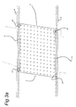
- aqueduct trough parts 23, 24 are shipped in via the canal, which are assembled on the bank 2 to form a complete aqueduct trough 25 (partially illustrated in Figure 3b).
- the aqueduct trough 25 is finished, it is pushed from the bank 2 over the columns 17 into the high position shown in Figure 4c. Then, the aqueduct trough 25 is moved down into the low position shown in Figure 4b. The bottom 26 of the aqueduct trough 25 then comes to lie on both caps 15, 16, while the front walls 27 of the aqueduct trough 25 come to lie against the columns 17, 18. In this position, the bottom 26 of the aqueduct trough 25 is sealed with respect to both caps 15, 16, and the front walls 27 are sealed with respect to the columns 17, 18. The water is removed from the space which is delimited by the walls 4, 5, 9, 10.
- the section of the cut-offs or partitions 3 which extends between both wall sections 4, 5 is removed.
- the floor 22 can be finished, together with the access and exit ramps 28 for the purpose of finishing the roadways for the traffic.
- a layer of concrete 45 is poured onto the bottom 26 of the aqueduct trough 25.
- a first step of producing a cap 15, 16 is shown.
- the cap is made by using a cap body or permanent form 31, which comprises the form halves 32, 33 which are connected by steel profiles 34.
- the permanent form 31 is placed over the upper side of the wall section 10; to this end, the tubular poles 6 are provided with ridges 35 on their upper end.
- the permanent form 31 is placed in the correct position on the tubular poles 6 by means of spacing plates 36.
- gravel 36 is poured on both sides of the permanent form 31, after which grout 37 is injected at the lower side of the permanent form 31.
- steel plates 39, 40 are provided, which play a part in the sealing of the aqueduct trough with respect to the caps.
- the permanent form 31 is cleaned on the inside and filled with concrete 38, as is illustrated in Figure 7.
- the concrete also engages with the ridges 35, so that the cap 16 which is obtained in this way is readily anchored with respect to the wall section 10.
- the aqueduct trough 25 is placed on top of them.
- the aqueduct trough 25, and particularly the floor 26 thereof, has a nose 30 which is supported on the caps 15, 16 by means of a block 29.
- Such an embodiment is also suitable for installing a second aqueduct trough 25', which rests on the caps 16 and a further cap (not shown) which is situated on a third wall (not shown either) which runs parallel to the two above-described walls.
- the bottom section 11 which is to the left of the caps 16 in Figure 7 is excavated to this end.
- the other aqueduct trough 25' has a nose 30 which is in a relatively high position and which, by means of a further block 29, can be supported on the nose 30 of the preceding aqueduct trough 25 .
- two passages or tunnels 42 have been created for road traffic, separated by the wall 4, 5, which wall 4, 5 is coated with panels 43, 44.
- the passage can also be produced under dry conditions.
- the underground has to have a water-impenetrable layer, such as greasy clay. This second possibility is explained with reference to Figs 10 and 11.
- the walls 4, 5 and the partitions 3 are put in place again.
- the walls 4, 5 are rammed into the bottom up to the water-impenetrable layer 50, as is also illustrated in Figs 10b and 10c.
- the aqueduct trough 25 is placed and sealed with respect to the walls 4, 5; 9, 10.
- the cut-offs or partitions 3 are also put in place.
- the area between the walls 4, 5 and below the positioned aqueduct trough 25 below and/or in the water-impenetrable layer is dry-excavated, as is illustrated in Figure 11c, as a result of which the passage 42 is formed.
- the cut-offs and partitions 3 are removed again.
- the bottom 52 is poured in the passage 42.
- the bottom is also poured between the walls 4, 5 at the location of the access and exit ramps.
- the walls and the roof of the passage 42 are coated.
Landscapes
- Engineering & Computer Science (AREA)
- General Engineering & Computer Science (AREA)
- Civil Engineering (AREA)
- Structural Engineering (AREA)
- Mechanical Engineering (AREA)
- Architecture (AREA)
- Sewage (AREA)
Abstract
Method for installing an aqueduct at a junction between a body of water and a thoroughfare as well as an aqueduct trough for use with the method, a set comprising two aqueduct trough parts and a cap body or permanent form.
In this case, two walls which extend at a distance from the thoroughfare are provided in the bottom of the body of water and in the adjacent banks by means of ramming. Subsequently, wet-excavating of the relevant bottom area between the walls is carried out and a floor is poured in the excavated area under water. Then, sealing with respect to the upper side of the wall sections takes place in such a manner that the longitudinal direction of the aqueduct trough produced is transverse to the longitudinal direction of the thoroughfare.
Description
- The invention relates to installing an aqueduct in a body of water, in particular at the junction between a canal or river and the like, and a road or railway line and the like. Various methods are known for carrying out such works, which each have their own specific advantages and disadvantages. These are connected, in the first place, to the restrictions caused to shipping during the construction of the aqueduct. Usually, a specific minimum width of passage will have to be maintained. A further important requirement which plays a part is the drainage function of the body of water. In this connection, the body of water will have to meet certain minimum requirements with respect to the flow rate. Furthermore, the costs which are connected to the installation of an aqueduct are an important factor.
- According to a first known option, a tunnel element is used, which is constructed at the entrance to the aqueduct. After the tunnel element has been constructed, it is moved to the correct position in the body of water and subsequently sunk into a trench which has been made beforehand in the bottom of the body of water. With a further possible method of producing an aqueduct, temporary construction pits are used. To this end, a construction pit is usually constructed first in one half of the body of water, which is subsequently removed and then a construction pit is constructed in the other half of the body of water.
- The latter method has the drawback that the work in the construction pits has to be carried out in succession, which results in a long construction time. This mainly plays a part in the case of phased construction of an aqueduct, for example when an existing junction is replaced. In this case, the junction, for example a bridge, has to remain open to traffic as normal while the first half of the aqueduct is being constructed immediately next to the bridge. Subsequently, the bridge can be demolished and the second half of the aqueduct can be constructed. Such a method of construction would require four construction pits in total, which results in a proportionally longer construction time.
- It is an object of the invention is therefore to provide a method for constructing an aqueduct in such a manner that shipping is only affected to a small degree and also in such a manner that the drainage function of the respective body of water can be ensured to a sufficient degree. It is also desirable if the construction time is limited and the costs should not be substantially higher than with the traditional construction methods. This object is achieved by means of a method for installing an aqueduct at a junction between a body of water and a thoroughfare, comprising the steps of:
- ramming at least two walls which are spaced apart and extend next to one another in the direction of the thoroughfare into the bottom of the body of water and into the adjacent banks,
- continuing the ramming operation on the banks until the upper side of the wall sections there is close to the ground level,
- continuing the ramming operation in the bottom of the body of water until the upper side of the wall sections there is close to the bottom of the body of water,
- providing an aqueduct trough comprising a bottom provided with two opposite longitudinal edges and two opposite transverse edges as well as upright front walls running along the longitudinal edges of the bottom, in which the transverse edges are free from the bottom,
- placing the aqueduct trough in a sealing manner on top of the upper side of the wall sections which have been rammed into the bottom of the body of water and with respect to the wall sections which have been rammed into the banks, in such a manner that the longitudinal direction of the aqueduct trough is transverse to the longitudinal direction of the thoroughfare,
- providing a passage or tunnel between the side walls.
- With the method according to the invention, a part of the works which are required to install the aqueduct are being carried out while there is open communication with the body of water. This means that actually, work is no longer carried out for a prolonged period of time in a drained compartment of the body of water, which is most important for maintaining the drainage function of the body of water during the works. In addition, keeping the body of water open for traffic is of course advantageous for the smooth flow of shipping traffic.
- There are several different possibilities for providing the passage or tunnel, depending on the soil conditions. According to a first possibility, the method according to the invention to this end comprises the steps of:
- wet-excavating at least the area delimited by the walls,
- producing a floor in the excavated area by pouring in concrete under water,
- subsequently placing the aqueduct trough,
- draining off the water inside the walls.
- One of the most important elements of this variant of the method according to the invention relates to pouring the floor for the future thoroughfare at the correct level and to installing the aqueduct trough on top of it. All of these components have to be placed in the body of water, so it is advantageous, in this connection, to provide a space which is insulated with respect to the environment, in particular with respect to the banks.
This can be achieved according to the invention by means of the steps of: - ramming in each case a cut-off or partition into and along both banks and causing both walls to intersect these cut-offs or partitions,
- initially only excavating the area which is delimited by these cut-offs or partitions and the walls.
- The cut-offs or partitions are only temporary and, together with the walls, delimit the working area for providing the floor and the aqueduct trough. Both banks are in this case well screened off against the working area, so that these can initially be preserved in the substantially original state before the access and exit ramps are constructed therein. The cut-offs or partitions, together with the walls, form a sealed-off area, but as the walls at the bottom of the body of water do not go beyond the level of the bottom, shipping can nevertheless take place unimpeded. The walls, which later delimit the walls of the thoroughfare under the aqueduct, are preferably constructed from alternately sheet pile planks and tubular poles which are provided with the same locking connections as the sheet pile planks. Such tubular poles provide sufficient strength and rigidity to the walls with respect to horizontal and vertical forces.
- In this enclosed area, the floor of the thoroughfare can then be constructed by carrying out the following steps:
- ramming foundation piles into the excavated area which is filled with water, to the extent that is necessary,
- pouring the floor in connection with these foundation piles.
- Once the floor has been poured, the aqueduct trough can be placed. Then the cut-off or partition sections which are situated between both walls can be removed after the aqueduct trough and the walls have been sealed with respect to one another.
- According to a second possibility, the method according to the invention to this end comprises the steps of:
- ramming the walls into the bottom up to a water-impenetrable layer,
- placing the aqueduct trough,
- subsequently dry-excavating the area below and/or in the water-impenetrable layer between the walls and below the aqueduct trough, so that the water-impenetrable layer remains intact,
- pouring a floor in the excavated area.
- In connection with the sealing of the aqueduct trough with respect to the walls, the finish of the upper side of the walls is very important. To this end, the so-called caps are used, which form the connection between the walls and the bottom of the aqueduct trough. The caps have a number of important functions, the most important of which is to act as the supporting beam for the aqueduct trough. In addition, the caps form connecting elements between the combination wall and the aqueduct trough.
- The caps play a particularly important part in transferring the vertical loads to the tubular poles. If desired, the connection can also transfer moments, but a so-called pin bearing is preferred. In this connection, the method according to the invention preferably comprises the steps of:
- producing a cap on the upper side of the wall sections which have been rammed into the bottom of the body of water,
- placing the aqueduct trough on the caps,
- sealing the aqueduct trough and the caps with respect to one another.
- Furthermore, the cap acts as a shuttering element for the wet intersection. In this connection, the method according to the invention may comprise the steps of:
- providing an anchoring profile on the head of the tubular poles,
- placing a prefabricated cap body or permanent form on and over the heads of the tubular poles,
- pouring gravel against the cap body,
- injecting grout between the gravel and the cap body,
- filling the space between the tubular poles and the cap body with concrete.
- This sealing may, for example, be effected by injecting grout between the gravel and the cap body.
- The caps can be accurately positioned with respect to the tubular poles, for example by using filler plates for adjusting the desired level of the caps. Since the cap body has been produced beforehand under dry and suitable conditions, it will satisfy the demands with regard to the desired accuracy and dimensional stability. As a result thereof, the faces of the caps which play a part in achieving the sealing action, can be readily controlled.
- The aqueduct trough furthermore has to be sealed in the correct manner with respect to the wall sections which have been rammed into the bank. In this connection, the method according to the invention may comprise the following steps:
- connecting concrete columns at both ends of each cap, which concrete columns run along the wall sections rammed into the banks,
- accommodating the aqueduct trough between these columns,
- sealing the aqueduct trough and the columns with respect to one another.
- The desired transfer of vertical forces from the aqueduct trough onto the walls can be achieved by means of the following steps:
- placing supporting blocks on the caps in line with the tubular poles,
- placing the aqueduct trough on the supporting blocks.
- The aqueduct trough is thus supported in a stable manner by the tubular poles, which are particularly suitable for absorbing such a vertical load.
- As has already been mentioned above, the method according to the invention is particularly suitable for the phased construction of an aqueduct with several tunnel tubes. In this connection, the method according to the invention may comprise the steps of:
- ramming a third wall into the bottom of the body of water and into the adjacent banks, at a distance from and next to one of the at least two walls,
- continuing the ramming operation on the banks until the upper side of the wall sections there is close to the ground level,
- continuing the ramming operation in the bottom of the body of water until the upper side of the wall section there of the third wall is close to the bottom of the body of water,
- providing a further aqueduct trough,
- placing the further aqueduct trough in a sealing manner on top of the upper side of the wall sections which have been rammed into the bottom of the body of water and with respect to the wall sections which have been rammed into the banks of the third wall and the adjacent wall, in such a manner that the longitudinal direction of the aqueduct trough is transverse to the longitudinal direction of the thoroughfare,
- sealing both aqueduct troughs with respect to one another,
- providing a further passage between the third wall and the adjacent wall.
- According to a first possibility, the passage can be formed under water. In that case, the method comprises the steps of:
- wet-excavating at least the area delimited by the third wall and the adjacent wall,
- producing a floor in the excavated area by pouring concrete under water,
- subsequently placing the further aqueduct trough,
- draining off the water which is between the third wall and the adjacent wall.
- According to a second possibility, the passage can also be produced under dry conditions. In order to achieve this, a water-impenetrable layer has to be present in the underground. In that case, the method comprises the steps of:
- ramming the third wall into the bottom up to a water-impenetrable bottom layer,
- placing the further aqueduct trough,
- subsequently dry-excavating the area below and/or in the water-impenetrable layer between the third wall and the adjacent wall and below the aqueduct trough, so that the water-impenetrable layer remains intact,
- pouring a floor in the excavated area.
- The cap which is provided on the central wall of the three walls acts as a supporting beam for both aqueduct troughs which are connected to one another. The bearing for these aqueduct troughs which are initially separate can be produced in a manner which is most advantageous with respect to transmitting the loads to the tubular poles of the central wall by means of the steps of:
- providing a nose in each case on those edges of the two aqueduct troughs which face one another,
- placing the nose of the further aqueduct trough on the nose of the other aqueduct trough.
- It is of course also possible to place the abovementioned supporting blocks between the respective noses, in line with the supporting blocks which are situated between the bottom nose and the wall.
- Preferably, the method comprises the steps of:
- dredging a trench in the bottom of the body of water,
- subsequently ramming the walls into the bottom of the body of water,
- continuing the ramming operation in the bottom of the body of water until the upper side of the wall sections there is at some distance, such as approximately 1 m, above the bottom of the trench.
- The aqueduct trough can be designed in various ways. One possibility which may be mentioned is a concrete variant, in which the aqueduct trough is constructed in situ from a relatively large number of concrete elements. However, preferably, the aqueduct trough is designed in the shape of a steel box structure, comprising a floor which forms the bottom of the body of water, and front walls which form the banks of the body of water. In order to achieve the desired bending stiffness of the floor, the method also comprises applying a concrete layer to the floor of the aqueduct trough.
- Such a steel aqueduct trough can be transported and installed by means of the steps of:
- transporting at least two separate aqueduct trough parts via the body of water,
- placing the aqueduct trough parts on one of the banks,
- connecting the aqueduct trough parts to one another in order to form the aqueduct trough,
- placing the aqueduct trough on the caps from the banks.
- The invention also relates to an aqueduct trough for use with the above-described method, comprising a steel box structure having a floor and upright front walls on either side of the floor. The invention also relates to a set which comprises at least two aqueduct trough parts for assembling the aqueduct trough.
- Furthermore, the invention comprises a cap body for use with the above-described method, which cap body comprises a head and downwardly pointing flanges on either side of the head. Since the cap, as described above, plays an important part in achieving the sealing between the aqueduct trough and the walls, the upper side of the head is preferably provided with at least one sealing surface together with sealing means for sealing the cap with respect to an aqueduct trough. In particular, these sealing surfaces are formed by a sealing plate. In particular, the upper side of the head may be provided with two sealing plates which are spaced apart and arranged above the flanges. The head may also be provided with openings for introducing a concrete filling.
- Below, the invention will be explained in more detail with reference to the figures, in which:
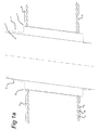
- Figs 1a and 1b show a first step in carrying out the method according to the invention.
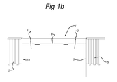
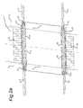
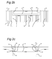
- Figs 2a-c show a second step according to a first variant of the method.
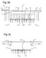
- Figs 3a-c show a third step.
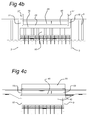
- Figs 4a-c show a fourth step.
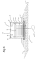
- Figs 5-9 show various stages during the production of caps and the placement of an aqueduct trough thereon.
- Figs 10a-c show a second step according to a second variant of the method.
- Figs 11a-c show a third step according to the second variant.
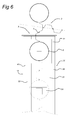
- Figure 1a shows a top view of a body of water, in this case a
canal 1, and of theadjacent banks 2, in each of which a cut-off orpartition 3 is provided. These cut-offs orpartitions 3 delimit a section of thecanal 1 in which an aqueduct trough has to be installed. In the cross section of Figure 1b, thecanal 1, the bottom 8 thereof, thebank 2 and the cut-offs orpartitions 3 have also been shown. - As has also been shown, in each case two
wall sections banks 2, which wall sections in particular comprisetubular poles 6 andsheet pile planks 7. Each of thesewall sections partition 3. As all the activities in connection with the installation of the cut-offs orpartitions 3 and thewall sections banks 2, the shipping traffic can continue to use thecanal 1 unimpeded. - As is shown in Figs 2a-c, in a next step,
wall sections wall sections partitions 3 and are in line with thewall sections banks 2. Thesewall sections canal 1. As is illustrated in Figure 2c, the bottom of thecanal 1 is preferably deepened tolevel 11, so that theupper side 12 of thewall sections level 11. As shown in Figure 2b, thisupper side 12 of thewall sections upper side 13 of thewall sections - Once the
wall sections gravel 14 is poured against thewall sections caps wall sections cap 16,columns wall sections Material 19 is also poured on those sides of thewall sections - After the first steps in carrying out the method have thus been taken, there are two different ways of finishing the construction of the aqueduct. According to a first possibility, as illustrated in Figs 3a-c, the bottom of the
canal 1 is subsequently dug out up to thelevel 20, as illustrated in Figs 3b and 3c. Thissection 20 is delimited by thewall sections partitions 3, as can be seen in the top view of Figure 3a. Foundation piles 21 are rammed into this excavatedbottom section 20, following which afloor 22 is poured in connection with the heads of the tension piles 21 which protrude from thebottom section 20. Then,aqueduct trough parts bank 2 to form a complete aqueduct trough 25 (partially illustrated in Figure 3b). - Once the
aqueduct trough 25 is finished, it is pushed from thebank 2 over thecolumns 17 into the high position shown in Figure 4c. Then, theaqueduct trough 25 is moved down into the low position shown in Figure 4b. The bottom 26 of theaqueduct trough 25 then comes to lie on bothcaps front walls 27 of theaqueduct trough 25 come to lie against thecolumns aqueduct trough 25 is sealed with respect to bothcaps front walls 27 are sealed with respect to thecolumns walls partitions 3 which extends between bothwall sections floor 22 can be finished, together with the access and exit ramps 28 for the purpose of finishing the roadways for the traffic. A layer ofconcrete 45 is poured onto the bottom 26 of theaqueduct trough 25. - In the cross section of Figure 5, a first step of producing a
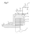
cap permanent form 31, which comprises the form halves 32, 33 which are connected by steel profiles 34. Thepermanent form 31 is placed over the upper side of thewall section 10; to this end, thetubular poles 6 are provided withridges 35 on their upper end. Thepermanent form 31 is placed in the correct position on thetubular poles 6 by means of spacingplates 36. Subsequently,gravel 36 is poured on both sides of thepermanent form 31, after whichgrout 37 is injected at the lower side of thepermanent form 31. At the upper side of both form halves 32, 33,steel plates - In the top view of Figure 6, the
permanent form 31 with the two form halves 32, 33 is also illustrated. As can also be seen in the top view of Figure 6, abearing 41 is formed at the end of the form halves 31, on which thecolumn 18 shown in Figure 8 is placed. - Subsequently, the
permanent form 31 is cleaned on the inside and filled withconcrete 38, as is illustrated in Figure 7. The concrete also engages with theridges 35, so that thecap 16 which is obtained in this way is readily anchored with respect to thewall section 10. - After the
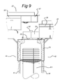
caps aqueduct trough 25 is placed on top of them. Theaqueduct trough 25, and particularly thefloor 26 thereof, has anose 30 which is supported on thecaps block 29. Such an embodiment is also suitable for installing a second aqueduct trough 25', which rests on thecaps 16 and a further cap (not shown) which is situated on a third wall (not shown either) which runs parallel to the two above-described walls. As illustrated in Figure 9, thebottom section 11 which is to the left of thecaps 16 in Figure 7 is excavated to this end. The other aqueduct trough 25' has anose 30 which is in a relatively high position and which, by means of afurther block 29, can be supported on thenose 30 of the precedingaqueduct trough 25 . Thus, two passages ortunnels 42 have been created for road traffic, separated by thewall wall panels - As all the activities mentioned above are carried out in the body of
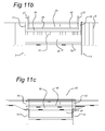
water 1, shipping traffic which uses this body of water is hardly affected by these activities. - According to a second possible embodiment of the method according to the invention, the passage can also be produced under dry conditions. In order to be able to achieve this, the underground has to have a water-impenetrable layer, such as greasy clay. This second possibility is explained with reference to Figs 10 and 11.
- As illustrated in Figure 10a, first the
walls partitions 3 are put in place again. Thewalls impenetrable layer 50, as is also illustrated in Figs 10b and 10c. In a next step, as is shown in Figs 10b and 11b, theaqueduct trough 25 is placed and sealed with respect to thewalls partitions 3 are also put in place. Subsequently, the area between thewalls aqueduct trough 25 below and/or in the water-impenetrable layer is dry-excavated, as is illustrated in Figure 11c, as a result of which thepassage 42 is formed. The cut-offs andpartitions 3 are removed again. In a subsequent step, the bottom 52 is poured in thepassage 42. The bottom is also poured between thewalls passage 42 are coated.
Claims (30)
- Method for installing an aqueduct at a junction between a body of water (1) and a thoroughfare (41, 42), comprising the steps of:- ramming at least two walls (4, 5; 9, 10) which are spaced apart and extend next to one another in the direction of the thoroughfare into the bottom (8, 11) of the body of water (1) and into the adjacent banks (2),- continuing the ramming operation on the banks (2) until the upper side of the wall sections (4, 5) there is close to the ground level,- continuing the ramming operation in the bottom of the body of water (1) until the upper side of the wall sections (9, 10) there is close to the bottom (8, 11) of the body of water (1),- providing an aqueduct trough (25, 25') comprising a bottom (26) provided with two opposite longitudinal edges and two opposite transverse edges as well as upright front walls (27) running along the longitudinal edges of the bottom, in which the transverse edges are free from the bottom (26),- placing the aqueduct trough (25, 25') in a sealing manner on top of the upper side of the wall sections (9,10) which have been rammed into the bottom (11) of the body of water (1) and against the wall sections (4, 5) which have been rammed into the banks (2), in such a manner that the longitudinal direction of the aqueduct trough (25, 25') is transverse to the longitudinal direction of the thoroughfare (41, 42),- providing a passage (42) or tunnel in the area between the walls (4, 5; 9, 10).
- Method according to Claim 1, comprising the steps of:- wet-excavating at least the bottom area (20) delimited by the walls (4, 5; 9, 10),- producing a floor (22) in the excavated area (20) by pouring in concrete under water,- subsequently placing the aqueduct trough (25, 25'),- draining off the water inside the walls (4, 5; 9, 10).
- Method according to Claim 2, comprising producing the floor (22) by means of the following steps:- ramming foundation piles (21) into the excavated area (20) which is filled with water, to the extent that is necessary,- pouring the floor (22) in connection with these foundation piles.
- Method according to Claim 1, comprising the steps of:- ramming the walls (4, 5; 9, 10) into the bottom up to a water-impenetrable layer (50),- placing the aqueduct trough (25, 25'),- subsequently dry-excavating the area below and/or in the water-impenetrable layer (50) between the walls (4, 5; 9, 10) and below the aqueduct trough (25, 25'), so that the water-impenetrable layer remains intact,- pouring a floor (52) in the excavated area.
- Method according to one of Claims 2-4, comprising the steps of:- ramming in each case a cut-off or partition (3) into and along both banks (2) and causing both walls (4, 5; 9, 10) to intersect these cut-offs or partitions (3).
- Method according to Claim 5, comprising also placing the cut-offs or partitions (3) on those sides of the walls (4, 5; 9, 10) which are remote from one another.
- Method according to Claim 6, comprising placing the cut-off or partition sections (3) which are situated between both walls (4, 5; 9, 10) at a distance from one another which is greater than the distance between the banks (2).
- Method according to Claim 7, comprising placing the cut-off or partition sections (3) which are situated outside both walls (4, 5; 9, 10) at a distance from one another which is smaller than the distance between the cut-off or partition sections (3) which are situated between both walls (4, 5; 9, 10).
- Method according to one of Claims 5-8, comprising the step of removing the cut-off or partition sections (3) which are situated between both walls (4, 5; 9, 10) after the floor (22) has been finished and after the aqueduct trough (25, 25') has been placed and after the aqueduct trough (25, 25') and the walls (4, 5; 9, 10) have been sealed with respect to one another.
- Method according to one of Claims 5-9 to the extent that it is dependent on Claim 3, comprising the step of:- only excavating the area which is delimited by the cut-offs or partitions (3) and the walls (4, 5; 9, 10).
- Method according to one of the preceding claims, comprising the steps of :- ramming a third wall into the bottom of the body of water and into the adjacent banks, at a distance from and next to one of the at least two walls,- continuing the ramming operation on the banks until the upper side of the wall section there of the third wall is close to the ground level,- continuing the ramming operation in the bottom of the body of water until the upper side of the wall section there of the third wall is close to the bottom of the body of water,- providing a further aqueduct trough (25'),- placing the further aqueduct trough (25') in a sealing manner on top of the upper side of the wall sections which have been rammed into the bottom of the body of water and with respect to the wall sections which have been rammed into the banks of the third wall and the adjacent wall, in such a manner that the longitudinal direction of the aqueduct trough is transverse to the longitudinal direction of the thoroughfare,- sealing both aqueduct troughs with respect to one another,- providing a further passage (42) or tunnel between the third wall and the adjacent wall.
- Method according to Claim 11, comprising the steps of:- providing a nose (30, 30') in each case on those edges of the two aqueduct troughs (25, 25') which face one another,- placing the nose (30') of the further aqueduct trough (25') on the nose (30) of the other aqueduct trough (25).
- Method according to Claim 11 or 12, comprising the steps of:- wet-excavating at least the bottom area delimited by the third wall and the adjacent wall,- producing a floor in the excavated area by pouring concrete under water,- subsequently placing the further aqueduct trough (25'),- draining off the water which is between the third wall and the adjacent wall.
- Method according to Claim 10 or 11, comprising the steps of:- ramming the third wall into the bottom up to a water-impenetrable layer (5),- placing the further aqueduct trough (25'),- subsequently dry-excavating the area below and/or in the water-impenetrable layer (50) between the third wall and the adjacent wall and below the aqueduct trough (25, 25'), so that the water-impenetrable layer (50) remains intact,- pouring a floor (52) in the excavated area.
- Method according to one of the preceding claims, comprising the step of :- using combination walls which are composed of sheet pile planks (7) and tubular poles (6).
- Method according to one of the preceding claims, comprising the steps of:- producing a cap (15, 16) on the upper side of the wall sections (9, 10) which have been rammed into the bottom (11) of the body of water (1),- placing the aqueduct trough (25, 25') on the caps (15, 16),- sealing the aqueduct trough (25, 25') and the caps (15, 16) with respect to one another.
- Method according to Claim 16, comprising the steps of:- providing an anchoring profile (33) on the head of the tubular poles (6),- placing a prefabricated cap body or permanent form (31) on and over the heads of the tubular poles (6),- pouring gravel (36) against the cap body (31),- injecting grout (37) between the gravel (36) and the cap body (31),- filling the space between the tubular poles (6) and the cap body with concrete (38).
- Method according to Claim 16 or 17, comprising the steps of:- connecting concrete columns (17, 18) at both ends of each cap (15, 16), which concrete columns (17, 18) run along the wall sections (4, 5) rammed into the banks (2),- accommodating the aqueduct trough (25, 25') between these columns (17, 18),- sealing the aqueduct trough (25, 25') and the columns (17, 18) with respect to one another.
- Method according to Claim 15 in combination with one of Claims 16-18, comprising the steps of:- placing supporting blocks (29) on the caps (15, 16) in line with the tubular poles (6),- placing the aqueduct trough (25, 25') on the supporting blocks (29).
- Method according to one of the preceding claims, comprising the steps of:- dredging a trench (11) in the bottom (8) of the body of water (1),- subsequently ramming the walls (9, 10) into the bottom of the body of water (1),- continuing the ramming operation in the bottom (11) of the body of water (1) until the upper side of the wall sections (9, 10) there is at some distance, such as approximately 1 m, above the bottom of the trench (11).
- Method according to one of the preceding claims, comprising designing each aqueduct trough (25) in the shape of a steel box structure, comprising a floor (26) which forms the bottom of the body of water (1), and front walls (27) which form the banks of the canal (1).
- Method according to Claim 21, comprising applying a concrete layer (45) to the floor of each aqueduct trough (25, 25').
- Method according to Claim 21 or 22, comprising the steps of:- transporting at least two separate aqueduct trough parts (23, 24) via the body of water (1),- placing the aqueduct trough parts on one of the banks (2),- connecting the aqueduct trough parts (23, 24) to one another in order to form the aqueduct trough (25, 25'),- placing the aqueduct trough (25, 25') on the caps (15, 16) from the bank (2).
- Aqueduct trough (25, 25') for use with the method according to one of Claims 21-23, comprising a steel box structure having a floor (26) and upright front walls (27) on either side of the floor (26).
- Set, comprising at least two aqueduct trough parts (23, 24) for use with the method according to Claim 23.
- Cap body or permanent form (31) for use with the method according to Claim 17, comprising a head (46) and downwardly pointing form halves (32, 33) on either side of the head (46).
- Cap body (31) according to Claim 26, in which the upper side of the head (46) is provided with at least one sealing surface (39, 40) for interacting with sealing means in order to seal the cap (15, 16) with respect to an aqueduct trough (25, 25').
- Cap body (31) according to Claim 27, in which each sealing surface is formed by a sealing plate (39, 40).
- Cap body (31) according to Claim 28, in which the upper side of the head (46) is provided with two sealing plates (39, 40) which are spaced apart and arranged above the flanges (47).
- Cap body (31) according to one of Claims 26-29, in which the form halves (32, 33) are connected to one another by profiles (34).
Applications Claiming Priority (1)
| Application Number | Priority Date | Filing Date | Title |
|---|---|---|---|
| NL2000148A NL2000148C2 (en) | 2006-07-19 | 2006-07-19 | Method for manufacturing an aqueduct. |
Publications (1)
| Publication Number | Publication Date |
|---|---|
| EP1887146A2 true EP1887146A2 (en) | 2008-02-13 |
Family
ID=37946457
Family Applications (1)
| Application Number | Title | Priority Date | Filing Date |
|---|---|---|---|
| EP20070112520 Withdrawn EP1887146A2 (en) | 2006-07-19 | 2007-07-16 | Method for producing an aqueduct |
Country Status (2)
| Country | Link |
|---|---|
| EP (1) | EP1887146A2 (en) |
| NL (1) | NL2000148C2 (en) |
Cited By (3)
| Publication number | Priority date | Publication date | Assignee | Title |
|---|---|---|---|---|
| CN113737734A (en) * | 2020-05-29 | 2021-12-03 | 广西建工集团海河水利建设有限责任公司 | U-shaped aqueduct truss type all-steel formwork construction method |
| CN118036161A (en) * | 2024-04-11 | 2024-05-14 | 江西省水利科学院(江西省大坝安全管理中心、江西省水资源管理中心) | Analysis method for durability of aqueduct structure |
| CN120030662A (en) * | 2025-04-22 | 2025-05-23 | 安徽省交通规划设计研究总院股份有限公司 | A design method for a steel truss beam and corrugated flume combined aqueduct connection structure |
Family Cites Families (1)
| Publication number | Priority date | Publication date | Assignee | Title |
|---|---|---|---|---|
| GB523632A (en) * | 1939-01-11 | 1940-07-18 | Beton En Aannemingsbedrijf Sys | Improvements in or relating to concrete foundation for the walls of buildings |
-
2006
- 2006-07-19 NL NL2000148A patent/NL2000148C2/en not_active IP Right Cessation
-
2007
- 2007-07-16 EP EP20070112520 patent/EP1887146A2/en not_active Withdrawn
Cited By (3)
| Publication number | Priority date | Publication date | Assignee | Title |
|---|---|---|---|---|
| CN113737734A (en) * | 2020-05-29 | 2021-12-03 | 广西建工集团海河水利建设有限责任公司 | U-shaped aqueduct truss type all-steel formwork construction method |
| CN118036161A (en) * | 2024-04-11 | 2024-05-14 | 江西省水利科学院(江西省大坝安全管理中心、江西省水资源管理中心) | Analysis method for durability of aqueduct structure |
| CN120030662A (en) * | 2025-04-22 | 2025-05-23 | 安徽省交通规划设计研究总院股份有限公司 | A design method for a steel truss beam and corrugated flume combined aqueduct connection structure |
Also Published As
| Publication number | Publication date |
|---|---|
| NL2000148C2 (en) | 2008-01-22 |
Similar Documents
| Publication | Publication Date | Title |
|---|---|---|
| KR100982827B1 (en) | Construction method of basement exterior wall applying the floor slab as the strut against the earth pressure from the temporary earth wall = TSW(Thrusting slabbed wall) method | |
| CA1046297A (en) | Precast element for the construction of trenched structures and the process related thereto | |
| KR101344063B1 (en) | The construction method of steel-concrete underpass | |
| KR20100009802A (en) | All precast concrete prefabricated water storage tank using precast concrete panel for retaining wall | |
| KR100938395B1 (en) | Construction method of underground roadway using steel composite wall pile | |
| CN114382011A (en) | Beam-free construction method of bridge and tunnel co-constructed structure | |
| KR101902791B1 (en) | Under ground structure construction method using composite steel pile and under ground structure therewith | |
| KR101183691B1 (en) | Water-storage tank of assembly type and method for constructing the same | |
| KR101293550B1 (en) | Construction method of underground structure | |
| EP1887146A2 (en) | Method for producing an aqueduct | |
| CN114395984A (en) | Beam construction method for bridge and tunnel co-constructed structure | |
| JP4083334B2 (en) | Underground structure having arch roof and method for constructing the same | |
| KR20080061580A (en) | Precast Concrete Slab Construction Method | |
| CN210194677U (en) | Underground prefabricated comprehensive pipe gallery | |
| KR100433653B1 (en) | Constructing method for the filling out abutement of bridge | |
| JP4092284B2 (en) | Rainwater underground seepage structure and its construction method | |
| CN216891933U (en) | Beam-free bridge-tunnel co-building structure | |
| CN216891932U (en) | Bridge and tunnel co-building structure with beam | |
| KR102426192B1 (en) | File fof retaining wall and construction method using file | |
| CN216809531U (en) | Riverbed scouring comprehensive protection structure | |
| CN214302989U (en) | Add on-ground prefabricated parking garage | |
| CN112267447B (en) | Sunken hydrophilic walkway under assembled bridge and hydrophilic walkway construction method | |
| KR101288602B1 (en) | Underpass using precast concrete pile and method for constructing the same | |
| JP6931876B2 (en) | How to build a permeable wall for slope reinforcement | |
| JP4451357B2 (en) | Reservoir pond equipment |
Legal Events
| Date | Code | Title | Description |
|---|---|---|---|
| PUAI | Public reference made under article 153(3) epc to a published international application that has entered the european phase |
Free format text: ORIGINAL CODE: 0009012 |
|
| AK | Designated contracting states |
Kind code of ref document: A2 Designated state(s): AT BE BG CH CY CZ DE DK EE ES FI FR GB GR HU IE IS IT LI LT LU LV MC MT NL PL PT RO SE SI SK TR |
|
| AX | Request for extension of the european patent |
Extension state: AL BA HR MK YU |
|
| STAA | Information on the status of an ep patent application or granted ep patent |
Free format text: STATUS: THE APPLICATION IS DEEMED TO BE WITHDRAWN |
|
| 18D | Application deemed to be withdrawn |
Effective date: 20140201 |