EP1886883A1 - Seat belt device - Google Patents
Seat belt device Download PDFInfo
- Publication number
- EP1886883A1 EP1886883A1 EP06746627A EP06746627A EP1886883A1 EP 1886883 A1 EP1886883 A1 EP 1886883A1 EP 06746627 A EP06746627 A EP 06746627A EP 06746627 A EP06746627 A EP 06746627A EP 1886883 A1 EP1886883 A1 EP 1886883A1
- Authority
- EP
- European Patent Office
- Prior art keywords
- spindle
- seat belt
- pawl
- electric actuator
- tensioner
- Prior art date
- Legal status (The legal status is an assumption and is not a legal conclusion. Google has not performed a legal analysis and makes no representation as to the accuracy of the status listed.)
- Granted
Links
- 230000005540 biological transmission Effects 0.000 claims abstract description 30
- 238000004804 winding Methods 0.000 abstract 1
- 238000006243 chemical reaction Methods 0.000 description 2
- 230000000452 restraining effect Effects 0.000 description 2
- 238000010521 absorption reaction Methods 0.000 description 1
- 239000000470 constituent Substances 0.000 description 1
- 230000003247 decreasing effect Effects 0.000 description 1
- 230000000694 effects Effects 0.000 description 1
- 239000002360 explosive Substances 0.000 description 1
- 239000004519 grease Substances 0.000 description 1
Images


Classifications
-
- B—PERFORMING OPERATIONS; TRANSPORTING
- B60—VEHICLES IN GENERAL
- B60R—VEHICLES, VEHICLE FITTINGS, OR VEHICLE PARTS, NOT OTHERWISE PROVIDED FOR
- B60R22/00—Safety belts or body harnesses in vehicles
- B60R22/34—Belt retractors, e.g. reels
- B60R22/3416—Unlocking devices for retractors
-
- B—PERFORMING OPERATIONS; TRANSPORTING
- B60—VEHICLES IN GENERAL
- B60R—VEHICLES, VEHICLE FITTINGS, OR VEHICLE PARTS, NOT OTHERWISE PROVIDED FOR
- B60R22/00—Safety belts or body harnesses in vehicles
- B60R22/28—Safety belts or body harnesses in vehicles incorporating energy-absorbing devices
-
- B—PERFORMING OPERATIONS; TRANSPORTING
- B60—VEHICLES IN GENERAL
- B60R—VEHICLES, VEHICLE FITTINGS, OR VEHICLE PARTS, NOT OTHERWISE PROVIDED FOR
- B60R22/00—Safety belts or body harnesses in vehicles
- B60R22/34—Belt retractors, e.g. reels
- B60R22/46—Reels with means to tension the belt in an emergency by forced winding up
- B60R22/4628—Reels with means to tension the belt in an emergency by forced winding up characterised by fluid actuators, e.g. pyrotechnic gas generators
-
- B—PERFORMING OPERATIONS; TRANSPORTING
- B60—VEHICLES IN GENERAL
- B60R—VEHICLES, VEHICLE FITTINGS, OR VEHICLE PARTS, NOT OTHERWISE PROVIDED FOR
- B60R22/00—Safety belts or body harnesses in vehicles
- B60R22/48—Control systems, alarms, or interlock systems, for the correct application of the belt or harness
-
- B—PERFORMING OPERATIONS; TRANSPORTING
- B60—VEHICLES IN GENERAL
- B60R—VEHICLES, VEHICLE FITTINGS, OR VEHICLE PARTS, NOT OTHERWISE PROVIDED FOR
- B60R22/00—Safety belts or body harnesses in vehicles
- B60R22/34—Belt retractors, e.g. reels
- B60R22/46—Reels with means to tension the belt in an emergency by forced winding up
- B60R22/4628—Reels with means to tension the belt in an emergency by forced winding up characterised by fluid actuators, e.g. pyrotechnic gas generators
- B60R2022/4642—Reels with means to tension the belt in an emergency by forced winding up characterised by fluid actuators, e.g. pyrotechnic gas generators the gas directly propelling a flexible driving means, e.g. a plurality of successive masses, in a tubular chamber
-
- B—PERFORMING OPERATIONS; TRANSPORTING
- B60—VEHICLES IN GENERAL
- B60R—VEHICLES, VEHICLE FITTINGS, OR VEHICLE PARTS, NOT OTHERWISE PROVIDED FOR
- B60R22/00—Safety belts or body harnesses in vehicles
- B60R22/34—Belt retractors, e.g. reels
- B60R22/46—Reels with means to tension the belt in an emergency by forced winding up
- B60R2022/4666—Reels with means to tension the belt in an emergency by forced winding up characterised by electric actuators
-
- B—PERFORMING OPERATIONS; TRANSPORTING
- B60—VEHICLES IN GENERAL
- B60R—VEHICLES, VEHICLE FITTINGS, OR VEHICLE PARTS, NOT OTHERWISE PROVIDED FOR
- B60R22/00—Safety belts or body harnesses in vehicles
- B60R22/34—Belt retractors, e.g. reels
- B60R22/46—Reels with means to tension the belt in an emergency by forced winding up
- B60R2022/468—Reels with means to tension the belt in an emergency by forced winding up characterised by clutching means between actuator and belt reel
Definitions
- the present invention relates to a seat belt device, and more particularly to a seat belt device which includes an electric actuator utilizing a motor and a pyrotechnic actuator (a pre-tensioner).
- Patent Document No. 1 JP-A-2003-191819
- the spindle for retracting the seat belt is desirably disconnected from the electric actuator.
- a main object of the invention is to provide a seat belt device including a seat belt retracting member such as a spindle for retracting the seat belt, a primary rotation source such as an electric actuator for rotating the seat belt retracting member when it is brought into connection with the seat belt retracting member, and a secondary rotation source such as a pre-tensioner for rotating the seat belt retracting member at faster speeds than the primary rotational source, wherein when the secondary rotation source such as the pre-tensioner is activated, the connection of the seat belt retracting member such as the spindle with the first rotation source such as a motor can be interrupted.
- a seat belt retracting member such as a spindle for retracting the seat belt
- a primary rotation source such as an electric actuator for rotating the seat belt retracting member when it is brought into connection with the seat belt retracting member
- a secondary rotation source such as a pre-tensioner for rotating the seat belt retracting member at faster speeds than the primary rotational source
- a seat belt device including:
- a seat belt device including:
- a seat belt device including:
- a seat belt device including:
- the seat belt device including the seat belt retracting member such as the spindle for retracting the seat belt, the primary rotation source such as the electric motor which is brought into connection with the seat belt retracting member to rotate the seat belt retracting member and the secondary rotation source such as the pre-tensioner for rotating the seat belt retracting member at faster speeds than the primary rotation source, wherein when the secondary rotation source such as the pre-tensioner is activated, the connection between the seat belt retracting member such as the spindle and the primary rotation source such as the motor can be interrupted.
- Fig. 1 is a schematic vertical sectional view which describes a seat belt device of a first embodiment of the invention
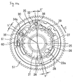
- Fig. 2 is a cutaway view taken along the line A-A and viewed in a direction indicated by arrows attached to the line in Fig. 1
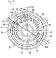
- Figs. 3 to 7 are vertical sectional views taken along the line B-B in Fig. 1 which describe the operations of a clutch for transmitting power from a motor
- Fig. 8 is an exploded schematic perspective view of the clutch for transmitting the power from the motor of the seat belt device of the first embodiment of the invention.
- a seat belt device 1 of this embodiment includes a spindle 11 for retracting a seat belt (webbing) 13, a pyrotechnic actuator (pre-tensioner) 14 connected to the spindle 11, a motor 55 as an electric actuator and a clutch 20 as a power transmission mechanism for power from the motor 55 to the spindle 11.
- a torsion bar 12 functioning as an energy absorbing mechanism is provided within the spindle 11 so as to be connected to the spindle 11.
- the pretensioner 14 includes a pinion 15 connected to the spindle 11, a tube 17 which accommodates balls 16 and a gas generator 18 provided at one end of the tube 17.
- the gas generator 18 When explosives are set alighted, the gas generator 18 generates gas, whereby the balls 16 accommodated within the tube 17 are strongly pushed out. The balls 16 which are so pushed out then move along a groove in the pinion 15 so as to rotate the spindle 11.
- the motor 55 is connected to a gear assembly 50, whereby the rotation of the motor 55 is decelerated by the gear assembly 50.
- the gear assembly 50 and the clutch 20 are accommodated within a container defined by a lower cover 21 and an upper cover 29.
- the clutch 20 includes a joint 24 connected to the spindle 11, a latch plate (a ratchet wheel) 27 integrated with the joint 24 to rotate together with the spindle 11, a final gear 51 of the gear assembly 50 which is gear connected to a rotational shaft of the motor 55, a pawl 32 mounted on the final gear 51 so as to rotate round a shaft 38 and adapted to be brought into engagement with a tooth of the latch plate (ratchet wheel) 27, a return spring 39 which is a biasing member for biasing the pawl 32 in a direction in which the pawl 32 is disconnected from the latch plate 27, a guide ring 30 provided inside the final gear 51 so as to be integral with the final gear 51, a clutch wheel 28 including three leg portions 42 which fit into three holes 41 in the guide ring 30 so as to rotate relatively at a required angle, a rotor cam 34 mounted on the clutch wheel 28 so as to rotate round a shaft 36 while mounted fixedly on the clutch wheel 28 by means of a fixing pin 37, whereby its rotation is prohibited in such
- a rib 28a is formed on the clutch wheel 28 in a predetermined position which extends in a circumferential direction, and one end portion of this rib 28a is situated in the vicinity of the pawl 32 when in an inoperative state where retraction by the motor 55 is not performed. Then, when the pawl 32 rotates due to a violently vehicle vibrating with the motor 55 in the inoperative state, the rib 28a is brought into abutment with the pawl 32 so as to prevent an abrupt rotation of the pawl 32 in a direction in which the pawl 32 is brought into engagement with the latch plate 27.
- the seat belt device of the embodiment When there is a possibility of collision, the seat belt 13 is retracted by the motor 55 before the possible collision, while when the possibility of collision disappears, the seat belt 13 is brought back to the state before the possible collision was sensed.
- the seat belt 13 is retracted by the pyrotechnic actuator (pre-tensioner) 14 at faster speeds than the retracting speed by the motor before collision, during which when a predetermined or more tension is applied to the seat belt 13, the tension is limited by the torsion bar 12.
- the final gear 51 which is gear connected to the rotational shaft of the motor 55, rotates in a counterclockwise direction (C direction).
- the pawl 32 which is mounted rotatably on the final gear 51, rotates to the latch plate 27 side along the cam surface 35 of the rotor cam 34 so as to start engagement with the latch plate 27.
- the pawl 32 is flicked out outwardly by a tooth surface of the latch plate 27 by virtue of the fast retracting rotation of the spindle 11 and the latch plate 27 integrated therewith.
- the rotor cam 34 is pushed by the pawl 32 and rotates outwardly about the shaft 36 of the clutch wheel 28.
- the pawl 32 and the rotor cam 34 are held on an outer circumferential portion by virtue of the biasing force of the return spring. Thereafter the power of the motor 55 is transmitted in no case to the spindle by the clutch 20.
- a seat belt device according to a second embodiment of the invention will be described in detail by reference to Figs. 9 to 12(c) . Note that like reference numerals will be imparted to like portions to those of the first embodiment, and the description thereof will be omitted or briefly made.
- a hold spring 60 as an elastic member is provided so as to hold a rotor cam 34a.
- the rotor cam 34a has an end portion 61 which extends to an opposite side of a shaft 36 to a side where a cam surface 35 is provided.
- the hold spring 60 is built on a clutch wheel 28 so as to be brought into abutment with the end portion 61 on the opposite side of the rotor cam 34a.
- the rotor cam 34a of this embodiment is mounted on the clutch wheel 28 so as to rotate round the shaft 36, and is fixed to the clutch wheel 28 so as not to rotate in such a state that the rotor cam 34a is biased by the hold spring 60. Furthermore, the rotor cam 34a is allowed to rotate when the biasing by the hold spring 60 is cancelled.
- a clutch 20a of this embodiment will be described. Firstly, when no retraction by a motor 55 is performed, as shown in Fig. 9 , a pawl 32 is disengaged from a latch plate 27 by virtue of the biasing force of a return spring 39. Due to this, only the latch plate 27 integrated with a spindle 11 rotates, whereby the normal retracting/stretching of the seat belt 13 is enabled.
- a final gear 51 gear connected to a rotational shaft of the motor 55 rotates in a counterclockwise direction (C direction).
- a friction spring 25 idly rotates until a circumferential edge portion of a hole 22a in a lower cover 21.
- the power transmission from the motor 55 is cut off by the clutch 20 at the time when the pre-tensioner 14 is activated, and the webbing is retracted by the pre-tensioner 14 without being subjected to power resistance by the motor 55 and the clutch 20. Therefore, it becomes possible to increase the retracting performance of the pre-tensioner 14.
- a seat belt device according to a third embodiment of the invention will be described in detail by reference to Figs. 13 to 15 .
- This embodiment differs from the first embodiment in the configuration of a gear assembly, and like reference numerals will be imparted to the other like constituent portions to those of the first embodiment, whereby the description thereof will be omitted or made briefly.
- a gear assembly 50a of this embodiment includes first to fourth gears 71, 72, 73, 74, and a tooth surface of the fourth gear 74 is in mesh engagement with a final gear 51.
- the first gear 71 is coupled to a motor shaft of a motor 55
- the second gear 72 has tooth surfaces 72a, 72b which are brought into mesh engagement with the first gear 71 and the third gear 73, respectively.
- the third gear 73 is a gear assembly with a torque limiter mechanism including a large diameter side gear (an actuator-side gear) 80, a plurality of limit springs (elastic pieces) 81 and a tubular small diameter side gear (spindle-side gear) 82.
- the small diameter side gear 82 has a shape in which a gear portion 82a meshing with the fourth gear 74, and a spring support portion 82c including slits 82b to which a plurality of limit springs 81 are assembled are coupled together in an axial direction.
- the large diameter side gear 80 has a tooth portion 80a meshing with the second gear 72 on an outer circumferential surface thereof. Further, the large diameter side gear 80 accommodates the spring support portion 82c and the limit springs 81 of the small diameter side gear 82 in an interior wall 80b and a bottom portion 80c thereof to which grease is applied.
- a plurality of concave locking surfaces 80d are formed at predetermined intervals on the interior wall 80b of the large diameter side gear 80. Projecting portions 81a formed on the limit springs 81 are brought into engagement with the locking surfaces 80d. In addition, the locking surfaces 80d are formed an integer number of times the number of the projecting portions 81a.
- the projecting portions 81a of the limit springs 81 are released from the engagement with the locking surfaces 80d and then start to slide along the interior wall 80b while being deformed. Then, due to the projecting portions 81a being brought into engagement with the adjacent locking surfaces 80d, a rotating deviation is generated between the large diameter side gear 80 and the small diameter side gear 82, and as shown in Fig. 13(b) , the fourth gear 74 and the final gear 51 rotate in a belt stretching direction. As a result, the transmission of excessive torque by the motor 55 is suppressed, whereby the failure of gear teeth can be prevented and the effect on the restraining performance during energy absorption operation can be decreased.
- the torque limiter mechanism is built in the third gear 73 of the gear assembly 50a, whereby although it is configured small, the torque limiter mechanism can increase the limiter torque of the spindle 11.
- gear assembly 50a is preferably applied to the seat belt device which includes the power transmission mechanism of the first or second embodiment, the application thereof is not limited thereto.
- the gear assembly 50a may be applied to known seat belt devices.
- limit spring 81 of the embodiment is mounted on the small diameter side gear 82, the limit spring 81 may be mounted on the large diameter side 80, so as to be brought into engagement with or disengagement from the locking surfaces provided on the small side gear 82.
Abstract
Description
- The present invention relates to a seat belt device, and more particularly to a seat belt device which includes an electric actuator utilizing a motor and a pyrotechnic actuator (a pre-tensioner).
- Conventionally, in a seat belt device of this type, when there is a possibility of collision, a seat belt (webbing) is retracted by the electric actuator before collision, and then the possibility of collision disappears, the seat belt is put back to the state before the possible collision was sensed, and when the collision occurs, the seat belt is retracted by the pre-tensioner (for example, refer to Patent Document No. 1).
Patent Document No. 1:JP-A-2003-191819 - In this way, in the seat belt device which includes the electric actuator which produces power to rotate a spindle and the pre-tensioner which produces another form of power to rotate the spindle, when the pre-tensioner is activated, the spindle for retracting the seat belt is desirably disconnected from the electric actuator.
- Consequently, a main object of the invention is to provide a seat belt device including a seat belt retracting member such as a spindle for retracting the seat belt, a primary rotation source such as an electric actuator for rotating the seat belt retracting member when it is brought into connection with the seat belt retracting member, and a secondary rotation source such as a pre-tensioner for rotating the seat belt retracting member at faster speeds than the primary rotational source, wherein when the secondary rotation source such as the pre-tensioner is activated, the connection of the seat belt retracting member such as the spindle with the first rotation source such as a motor can be interrupted.
- According to the invention, there is provided a seat belt device including:
- a spindle for retracting a seat belt;
- an electric actuator for generating power for rotating the spindle;
- an electric actuator for generating another form of power for rotating the spindle; and
- a power transmission mechanism for transmitting the power from the electric actuator to the spindle, wherein
- the power transmission mechanism can reversibly switch the connection and disconnection between the electric actuator and the spindle before the pre-tensioner is activated, while when the pre-tensioner is activated, the power transmission mechanism non-reversibly interrupts the connection between the electric actuator and the spindle.
- In addition, according to the invention, there is provided a seat belt device including:
- a spindle for retracting a seat belt;
- an electric actuator for generating power for rotating the spindle;
- a pre-tensioner for generating another form of power for rotating the spindle; and
- a power transmission mechanism for transmitting the power from the electric actuator to the spindle, wherein
- when the pre-tensioner is activated, the power transmission mechanism interrupts the connection between the electric actuator and the pre-tensioner by making use of the rotation of the spindle by the pre-tensioner.
- In addition, according to the invention, there is provided a seat belt device including:
- a seat belt retracting member for retracting a seat belt;
- a primary rotation source for rotating the seat belt retracting member when it is brought into connection with the seat belt retracting member;
- a secondary rotation source for rotating the seat belt retracting member at faster speeds than the primary rotation source; and
- a power transmission mechanism, wherein
- the power transmission mechanism can reversibly switch the connection and disconnection between the primary rotation source and the seat belt retracting member before the secondary rotation source is activated, while when the secondary rotation source is activated, the power transmission mechanism non-reversibly interrupts the connection between the first rotation source and the seat belt retracting member.
- Furthermore, according to the invention, there is provided a seat belt device including:
- a spindle for retracting a seat belt;
- an electric actuator for generating power for rotating the spindle; and
- a power transmission mechanism for transmitting the power from the electric actuator to the spindle, wherein
- the power transmission mechanism has an actuator-side gear to which the power from the electric actuator is transmitted, a spindle-side gear which is provided on the spindle's side and an elastic piece which is mounted either of the actuator-side gear and the spindle-side gear and which can be brought into engagement with the other gear and includes a torque limiter in which when a torque difference which is larger than a predetermined value is generated between the actuator-side gear and the spindle-side gear, the elastic piece cancels the engagement with the other gear so as to move relative to the other gear so that the torque difference becomes equal to or less than the predetermined value.
- According to the invention, there is provided the seat belt device including the seat belt retracting member such as the spindle for retracting the seat belt, the primary rotation source such as the electric motor which is brought into connection with the seat belt retracting member to rotate the seat belt retracting member and the secondary rotation source such as the pre-tensioner for rotating the seat belt retracting member at faster speeds than the primary rotation source, wherein when the secondary rotation source such as the pre-tensioner is activated, the connection between the seat belt retracting member such as the spindle and the primary rotation source such as the motor can be interrupted.
-
- [
Fig. 1 ] A schematic vertical sectional view which explains a seat belt device of a first embodiment of the invention. - [
Fig. 2 ] A cutaway view taken along the line A-A and viewed in a direction indicated by arrows attached to the line inFig. 1 . - [
Fig. 3 ] A vertical sectional view taken along the line B-B inFig. 1 , which explains the operation of a clutch for transmitting power from a motor. - [
Fig. 4 ] A vertical sectional view taken along the line B-B inFig. 1 , which explains the operation of the clutch for transmitting power from the motor. - [
Fig. 5 ] A vertical sectional view taken along the line B-B inFig. 1 , which explains the operation of the clutch for transmitting power from the motor. - [
Fig. 6 ] A vertical sectional view taken along the line B-B inFig. 1 , which explains the operation of the clutch for transmitting power from the motor. - [
Fig. 7 ] A vertical sectional view taken along the line B-B inFig. 1 , which explains the operation of the clutch for transmitting power from the motor. - [
Fig. 8 ] An exploded schematic perspective view of the clutch for transmitting the power from the motor of the seat belt device of the first embodiment of the invention. - [
Fig. 9 ] A view corresponding to the vertical sectional view taken along the line B-B inFig. 1 which explains a clutch in an inoperative state of a seat belt device of a second embodiment of the invention. - [
Fig. 10a ] A view corresponding to the vertical sectional view taken along the line B-B inFig. 1 which explains the clutch of the seat belt device of the second embodiment of the invention while a retraction by a motor is in operation. - [
Fig. 10b ] A view corresponding to the vertical sectional view taken along the line B-B inFig. 1 which explains the clutch of the seat belt device of the second embodiment of the invention while the retraction by the motor is in operation. [Fig. 10c ] A view corresponding to the vertical sectional view taken along the line B-B inFig. 1 which explains the clutch of the seat belt device of the second embodiment of the invention while the retraction by the motor is in operation. [Fig. 11a ] A view corresponding to the vertical sectional view taken along the line B-B inFig. 1 which explains the clutch of the seat belt device of the second embodiment of the invention when the retraction by the motor is cancelled. - [
Fig. 11b ] A view corresponding to the vertical sectional view taken along the line B-B inFig. 1 which explains the clutch of the seat belt device of the second embodiment of the invention when the retraction by the motor is cancelled. - [
Fig. 11c ] A view corresponding to the vertical sectional view taken along the line B-B inFig. 1 which explains the clutch of the seat belt device of the second embodiment of the invention when the retraction by the motor is cancelled. - [
Fig. 12a ] A view corresponding to the vertical sectional view taken along the line B-B inFig. 1 which explains the clutch of the seat belt device of the second embodiment of the invention while a pre-tensioner is in operation. - [
Fig. 12b ] A view corresponding to the vertical sectional view taken along the line B-B inFig. 1 which explains the clutch of the seat belt device of the second embodiment of the invention while the pre-tensioner is in operation. - [
Fig. 12c ] A view corresponding to the vertical sectional view taken along the line B-B inFig. 1 which explains the clutch of the seat belt device of the second embodiment of the invention while the pre-tensioner is in operation. - [
Fig. 13 ] Views which explain a gear assembly of a seat belt device of a third embodiment of the invention. - [
Fig. 14 ] A view which explains a gear having a torque limiter inFig. 13 . - [
Fig. 15 ] Views which explain a torque limiting operation of the gear having the torque limiter. -
- 1 seat belt device;
- 11 spindle;
- 12 torsion bar (energy absorbing mechanism;
- 13 seat belt (webbing);
- 14 pre-tensioner;
- 15 pinion;
- 16 ball;
- 17 tube;
- 18 gas generator;
- 20, 20a clutch;
- 21 lower cover;
- 22 recessed portion;
- 22a hole;
- 23 bush;
- 24 joint;
- 25 friction spring;
- 26 end portion;
- 27 latch plate (ratchet wheel, primary engagement member);
- 28 clutch wheel (friction wheel);
- 29 upper cover;
- 30 guide ring;
- 31 bush;
- 32 pawl (secondary engagement member);
- 34, 34a rotor cam (cam member, restricting member);
- 35 cam surface;
- 36 shaft;
- 37 fixing pin;
- 38 shaft;
- 41, 41a hole;
- 42, 42a leg portion;
- 39 return spring;
- 50 gear assembly;
- 51 final gear (rotary member);
- 55 motor;
- 71 first gear;
- 72 second gear;
- 73 third gear;
- 74 fourth gear;
- 80 large diameter side gear (actuator-side gear);
- 80d locking surface;
- 81 limit spring (elastic piece);
- 81a projecting portion;
- 82 small diameter side gear (spindle-side gear)
- Next, seat belt devices of respective embodiments of the invention will be described by reference to the drawings.
-
Fig. 1 is a schematic vertical sectional view which describes a seat belt device of a first embodiment of the invention,Fig. 2 is a cutaway view taken along the line A-A and viewed in a direction indicated by arrows attached to the line inFig. 1 ,Figs. 3 to 7 are vertical sectional views taken along the line B-B inFig. 1 which describe the operations of a clutch for transmitting power from a motor, andFig. 8 is an exploded schematic perspective view of the clutch for transmitting the power from the motor of the seat belt device of the first embodiment of the invention. - A seat belt device 1 of this embodiment includes
aspindle 11 for retracting a seat belt (webbing) 13,
a pyrotechnic actuator (pre-tensioner) 14 connected to thespindle 11,
amotor 55 as an electric actuator and
a clutch 20 as a power transmission mechanism for power from themotor 55 to thespindle 11.
Atorsion bar 12 functioning as an energy absorbing mechanism is provided within thespindle 11 so as to be connected to thespindle 11. - The
pretensioner 14 includes apinion 15 connected to thespindle 11, atube 17 which accommodatesballs 16 and agas generator 18 provided at one end of thetube 17. When explosives are set alighted, thegas generator 18 generates gas, whereby theballs 16 accommodated within thetube 17 are strongly pushed out. Theballs 16 which are so pushed out then move along a groove in thepinion 15 so as to rotate thespindle 11. - The
motor 55 is connected to agear assembly 50, whereby the rotation of themotor 55 is decelerated by thegear assembly 50. Thegear assembly 50 and the clutch 20 are accommodated within a container defined by alower cover 21 and anupper cover 29. - The clutch 20 includes
a joint 24 connected to thespindle 11,
a latch plate (a ratchet wheel) 27 integrated with the joint 24 to rotate together with thespindle 11,
afinal gear 51 of thegear assembly 50 which is gear connected to a rotational shaft of themotor 55,
apawl 32 mounted on thefinal gear 51 so as to rotate round ashaft 38 and adapted to be brought into engagement with a tooth of the latch plate (ratchet wheel) 27,
areturn spring 39 which is a biasing member for biasing thepawl 32 in a direction in which thepawl 32 is disconnected from thelatch plate 27,
aguide ring 30 provided inside thefinal gear 51 so as to be integral with thefinal gear 51,
aclutch wheel 28 including threeleg portions 42 which fit into threeholes 41 in theguide ring 30 so as to rotate relatively at a required angle,
arotor cam 34 mounted on theclutch wheel 28 so as to rotate round ashaft 36 while mounted fixedly on theclutch wheel 28 by means of a fixingpin 37, whereby its rotation is prohibited in such a state that it is fixed to theclutch wheel 28 by the fixingpin 37, while its rotation is allowed due to the fixingpin 37 being broken,
afriction spring 25 mounted on thelower cover 21 by anend portion 26 being caused to fit in a recessedportion 22 in thelower cover 21 and connected with theclutch wheel 28 by virtue of friction sliding, and
bushes
One end of thepawl 32 moves along acam surface 35 of therotor cam 34. - In addition, a
rib 28a is formed on theclutch wheel 28 in a predetermined position which extends in a circumferential direction, and one end portion of thisrib 28a is situated in the vicinity of thepawl 32 when in an inoperative state where retraction by themotor 55 is not performed. Then, when thepawl 32 rotates due to a violently vehicle vibrating with themotor 55 in the inoperative state, therib 28a is brought into abutment with thepawl 32 so as to prevent an abrupt rotation of thepawl 32 in a direction in which thepawl 32 is brought into engagement with thelatch plate 27. - Next, the operation of the seat belt device of the embodiment will be described.
When there is a possibility of collision, theseat belt 13 is retracted by themotor 55 before the possible collision, while when the possibility of collision disappears, theseat belt 13 is brought back to the state before the possible collision was sensed. When a collision occurs, theseat belt 13 is retracted by the pyrotechnic actuator (pre-tensioner) 14 at faster speeds than the retracting speed by the motor before collision, during which when a predetermined or more tension is applied to theseat belt 13, the tension is limited by thetorsion bar 12. - Next, the operation of the clutch 20 will be described.
Firstly, as shown inFig. 3 , when no retraction is performed by themotor 55, thelatch plate 27 and thepawl 32 are out of engagement. Only thelatch plate 27 integrated with thespindle 11 rotates, and normal retracting/stretching of theseat belt 13 can be performed. - As shown in
Fig. 4 , when themotor 55 rotates in a retracting direction, thefinal gear 51, which is gear connected to the rotational shaft of themotor 55, rotates in a counterclockwise direction (C direction). Thepawl 32, which is mounted rotatably on thefinal gear 51, rotates to thelatch plate 27 side along thecam surface 35 of therotor cam 34 so as to start engagement with thelatch plate 27. - As shown in
Fig. 5 , when thepawl 32 is brought into engagement with thelatch plate 27, the rotation of thefinal gear 51 is transmitted to thespindle 11 via thelatch plate 27, whereby theseat belt 13 is started to be retracted. As this occurs, therotor cam 34 rotates together with theclutch wheel 28 while friction sliding relative to thefriction spring 25. - As shown in
Fig. 6 , when themotor 55 rotates in releasing direction, in response to the rotation, thefinal gear 51 rotates in the releasing direction (clockwise direction: D direction). While thepawl 32 rotates together with thefinal gear 51, theclutch wheel 28 and therotor cam 34 mounted on theclutch wheel 28, are maintained by thefriction spring 25. Thepawl 32 departs from the latch plate along thecam surface 35 of therotor cam 34 by virtue of the biasing force of thereturn spring 39, whereby thepawl 32 is disengaged from the latch plate. - As shown in
Fig. 7 , when the pre-tensioner 14 is activated, thepawl 32 is flicked out outwardly by a tooth surface of thelatch plate 27 by virtue of the fast retracting rotation of thespindle 11 and thelatch plate 27 integrated therewith. At the same time, therotor cam 34 is pushed by thepawl 32 and rotates outwardly about theshaft 36 of theclutch wheel 28. As a result, thepawl 32 and therotor cam 34 are held on an outer circumferential portion by virtue of the biasing force of the return spring. Thereafter the power of themotor 55 is transmitted in no case to the spindle by the clutch 20. - Next, a seat belt device according to a second embodiment of the invention will be described in detail by reference to
Figs. 9 to 12(c) . Note that like reference numerals will be imparted to like portions to those of the first embodiment, and the description thereof will be omitted or briefly made. - In this embodiment, in place of the fixing
pin 37 of the first embodiment, ahold spring 60 as an elastic member is provided so as to hold arotor cam 34a. Namely, therotor cam 34a has anend portion 61 which extends to an opposite side of ashaft 36 to a side where acam surface 35 is provided. In addition, thehold spring 60 is built on aclutch wheel 28 so as to be brought into abutment with theend portion 61 on the opposite side of therotor cam 34a. - By this configuration, the
rotor cam 34a of this embodiment is mounted on theclutch wheel 28 so as to rotate round theshaft 36, and is fixed to theclutch wheel 28 so as not to rotate in such a state that therotor cam 34a is biased by thehold spring 60. Furthermore, therotor cam 34a is allowed to rotate when the biasing by thehold spring 60 is cancelled. - Next, the operation of a clutch 20a of this embodiment will be described.
Firstly, when no retraction by amotor 55 is performed, as shown inFig. 9 , apawl 32 is disengaged from alatch plate 27 by virtue of the biasing force of areturn spring 39. Due to this, only thelatch plate 27 integrated with aspindle 11 rotates, whereby the normal retracting/stretching of theseat belt 13 is enabled. - Next, when the
motor 55 rotates in a retracting direction, as shown inFig. 10(a) , afinal gear 51 gear connected to a rotational shaft of themotor 55 rotates in a counterclockwise direction (C direction). When thefinal gear 51 rotates, afriction spring 25 idly rotates until a circumferential edge portion of ahole 22a in alower cover 21. - When the
motor 55 rotates in the retracting direction further, as shown inFig. 10(b) , theclutch wheel 28 is fixed by virtue of the frictional force of thefriction spring 25, whereby only thefinal gear 51 rotates. In addition, thepawl 32 rotatably supported on aguide ring 30 rotates to thelatch plate 27 side along thecam surface 35 of therotor cam 34a against the biasing force of thereturn spring 39, so as to start engagement with thelatch plate 27. Furthermore, when thefinal gear 51 rotates,leg portions 42a of theclutch wheel 28 are brought into abutment with circumferential edge portions ofholes 41a of theguide ring 30, whereby thefinal gear 51 and theclutch wheel 28 rotate together. - In addition, as shown in
Fig. 10(c) , when thepawl 32 is brought into engagement with thelatch plate 27, the rotation of thefinal gear 51 is transmitted to thespindle 11 via thelatch plate 27, whereby the retracting of theseat belt 13 is started. - In addition, as shown in
Fig. 11(a) , when themotor 55 rotates in releasing direction, in response to the rotation, thefinal gear 51 rotates in the releasing direction (clockwise direction: D direction). Along with this, the webbing is stretched out by virtue of a reaction force from an occupant which is acting on the webbing, and theclutch wheel 28 and thelatch plate 27 rotate together by such an extent that the friction spring rotates idly. Thereafter, as shown inFig. 11(b) , theclutch wheel 28 is fixed by virtue of the biasing force of thefriction spring 25, whereby only thefinal gear 51 and thelatch plate 27 rotate in the releasing direction. Thelatch plate 27 maintains a meshing state with thepawl 32 while it is rotating in association with the rotation of thefinal gear 51. - Then, as shown in
Fig. 11(c) , when there is no reaction force coming from the occupant and the rotation of thelatch plate 27 together with thespindle 11 in the stretching direction ends, thefinal gear 51 rotates further. Accordingly, the engagement between thepawl 32 and thelatch plate 27 is interrupted and an initial state is thereby restored. - In addition, as shown in
Fig. 12(a) , when the pre-tensioner 14 is activated in such a state that the motor rotates in the retracting direction, thepawl 32 is flicked out outwardly by a tooth surface of thelatch plate 27 by virtue of the fast retracting rotation of thespindle 11 and thelatch plate 27 integrated therewith. - Then, as shown in
Fig. 12(b) , when thepawl 32 is brought into abutment with therotor cam 34 to thereby push therotor cam 34 outwards, therotor cam 34 rotates about theshaft 36, whereby the pressure from thehold spring 60 built on theclutch wheel 28 is released (refer toFig. 12(c) ). Thereafter, thepawl 32 and therotor cam 34 are held on an outer circumferential portion of theguide ring 30 by virtue of the biasing force of thereturn spring 39. Therefore, the rotation of themotor 55 is transmitted in no case to thespindle 11 by the clutch 20. - Consequently, also in the seat belt device of this embodiment, the power transmission from the
motor 55 is cut off by the clutch 20 at the time when the pre-tensioner 14 is activated, and the webbing is retracted by the pre-tensioner 14 without being subjected to power resistance by themotor 55 and the clutch 20. Therefore, it becomes possible to increase the retracting performance of the pre-tensioner 14. - Furthermore, while an energy absorbing operation is performed by the
torsion bar 12, the power resistance of themotor 55 and the clutch 20 is added in no case to the belt stretching load, thereby making it possible to increase the restraining performance. - Next, a seat belt device according to a third embodiment of the invention will be described in detail by reference to
Figs. 13 to 15 . This embodiment differs from the first embodiment in the configuration of a gear assembly, and like reference numerals will be imparted to the other like constituent portions to those of the first embodiment, whereby the description thereof will be omitted or made briefly. - As shown in
Fig. 13 , a gear assembly 50a of this embodiment includes first tofourth gears fourth gear 74 is in mesh engagement with afinal gear 51. Thefirst gear 71 is coupled to a motor shaft of amotor 55, and thesecond gear 72 hastooth surfaces first gear 71 and thethird gear 73, respectively. As shown inFig. 14 , thethird gear 73 is a gear assembly with a torque limiter mechanism including a large diameter side gear (an actuator-side gear) 80, a plurality of limit springs (elastic pieces) 81 and a tubular small diameter side gear (spindle-side gear) 82. - The small
diameter side gear 82 has a shape in which agear portion 82a meshing with thefourth gear 74, and aspring support portion 82c including slits 82b to which a plurality of limit springs 81 are assembled are coupled together in an axial direction.
The largediameter side gear 80 has atooth portion 80a meshing with thesecond gear 72 on an outer circumferential surface thereof. Further, the largediameter side gear 80 accommodates thespring support portion 82c and the limit springs 81 of the smalldiameter side gear 82 in an interior wall 80b and abottom portion 80c thereof to which grease is applied. - A plurality of
concave locking surfaces 80d are formed at predetermined intervals on the interior wall 80b of the largediameter side gear 80. Projectingportions 81a formed on the limit springs 81 are brought into engagement with the locking surfaces 80d. In addition, the locking surfaces 80d are formed an integer number of times the number of the projectingportions 81a. - Next, the operation of the torque limiter mechanism will be described.
In the normal state, as shown inFig. 13(a) , the phases of the largediameter side gear 80 and the smalldiameter side gear 82 of thethird gear 73 are held relative to each other. The largediameter side gear 80 and the smalldiameter side gear 82 rotate in the same direction in the retracting direction shown by a solid line or the releasing direction shown by a broken line. Here, when retracting is performed by driving themotor 55, in the event that a torque difference larger than a predetermined value is generated between the largediameter side gear 80 and the smalldiameter side gear 82 due to a light collision or braking which does not activate the pre-tensioner 14, as shown inFig. 15 , the projectingportions 81a of the limit springs 81 are released from the engagement with the locking surfaces 80d and then start to slide along the interior wall 80b while being deformed.
Then, due to the projectingportions 81a being brought into engagement with theadjacent locking surfaces 80d, a rotating deviation is generated between the largediameter side gear 80 and the smalldiameter side gear 82, and as shown inFig. 13(b) , thefourth gear 74 and thefinal gear 51 rotate in a belt stretching direction. As a result, the transmission of excessive torque by themotor 55 is suppressed, whereby the failure of gear teeth can be prevented and the effect on the restraining performance during energy absorption operation can be decreased. - In addition, the torque limiter mechanism is built in the
third gear 73 of the gear assembly 50a, whereby although it is configured small, the torque limiter mechanism can increase the limiter torque of thespindle 11. - In addition, while the gear assembly 50a is preferably applied to the seat belt device which includes the power transmission mechanism of the first or second embodiment, the application thereof is not limited thereto. The gear assembly 50a may be applied to known seat belt devices.
Additionally, while thelimit spring 81 of the embodiment is mounted on the smalldiameter side gear 82, thelimit spring 81 may be mounted on thelarge diameter side 80, so as to be brought into engagement with or disengagement from the locking surfaces provided on thesmall side gear 82. - Note that the invention is not limited to the embodiments that have been described above but can be modified or improved as required.
In addition, this patent application is based on theJapanese Patent Application (No. 2005-146173) filed on May 19, 2005
Claims (14)
when the pre-tensioner is activated, the electric actuator and the spindle are non-reversibly disconnected from each other by making use of the rotation of the spindle by the pre-tensioner.
the electric actuator is connected with the spindle by the power transmission mechanism, and wherein
when the pre-tensioner is activated while the spindle is being rotated by the electric actuator, the electric actuator and the spindle are non-reversibly disconnected from each other.
the power transmission system comprises:
the power transmission mechanism comprises:
a biasing member which biasing the pawl in a direction in which the pawl is released from the ratchet wheel,
wherein after the fixing member of the cam member fails, the cam member is biased in a direction in which the cam member moves away from the ratchet wheel via the pawl by virtue of biasing force of the biasing member.
the power transmission mechanism comprises:
the cam member is rotatably mounted on the friction wheel, and
the rotation of the cam member is prohibited in such a state that the cam member is mounted on the friction wheel by being biased by the elastic member, while the cam member is allowed to rotate due to the release of the biasing of the elastic member.
a biasing member which biases the pawl in a direction in which the pawl is released from the ratchet wheel,
wherein after the biasing of the cam member by the elastic member is released, the cam member is biased in a direction in which the cam member moves away from the ratchet wheel via the pawl by virtue of biasing force of the biasing member.
an actuator-side gear to which the power from the electric actuator is transmitted,
a spindle-side gear which is provided on the spindle's side and
an elastic piece which is mounted either of the actuator-side gear and the spindle-side gear and which is capable of being brought into engagement with the other gear and includes a torque limiter in which when a torque difference which is larger than a predetermined value is generated between the actuator-side gear and the spindle-side gear, the elastic piece cancels the engagement with the other gear so as to move relative to the other gear so that the torque difference becomes equal to or less than a predetermined value.
Priority Applications (1)
| Application Number | Priority Date | Filing Date | Title |
|---|---|---|---|
| EP15201380.1A EP3069938B1 (en) | 2005-05-19 | 2006-05-18 | Seat belt device |
Applications Claiming Priority (2)
| Application Number | Priority Date | Filing Date | Title |
|---|---|---|---|
| JP2005146173 | 2005-05-19 | ||
| PCT/JP2006/309960 WO2006123750A1 (en) | 2005-05-19 | 2006-05-18 | Seat belt device |
Related Child Applications (2)
| Application Number | Title | Priority Date | Filing Date |
|---|---|---|---|
| EP15201380.1A Division-Into EP3069938B1 (en) | 2005-05-19 | 2006-05-18 | Seat belt device |
| EP15201380.1A Division EP3069938B1 (en) | 2005-05-19 | 2006-05-18 | Seat belt device |
Publications (3)
| Publication Number | Publication Date |
|---|---|
| EP1886883A1 true EP1886883A1 (en) | 2008-02-13 |
| EP1886883A4 EP1886883A4 (en) | 2011-11-02 |
| EP1886883B1 EP1886883B1 (en) | 2016-05-04 |
Family
ID=37431322
Family Applications (2)
| Application Number | Title | Priority Date | Filing Date |
|---|---|---|---|
| EP06746627.6A Active EP1886883B1 (en) | 2005-05-19 | 2006-05-18 | Seat belt device |
| EP15201380.1A Active EP3069938B1 (en) | 2005-05-19 | 2006-05-18 | Seat belt device |
Family Applications After (1)
| Application Number | Title | Priority Date | Filing Date |
|---|---|---|---|
| EP15201380.1A Active EP3069938B1 (en) | 2005-05-19 | 2006-05-18 | Seat belt device |
Country Status (6)
| Country | Link |
|---|---|
| US (3) | US8777147B2 (en) |
| EP (2) | EP1886883B1 (en) |
| JP (1) | JP4854662B2 (en) |
| KR (2) | KR100983735B1 (en) |
| CN (1) | CN101180195B (en) |
| WO (1) | WO2006123750A1 (en) |
Cited By (6)
| Publication number | Priority date | Publication date | Assignee | Title |
|---|---|---|---|---|
| WO2009086819A3 (en) * | 2008-01-11 | 2009-09-11 | Takata-Petri Ag | Belt retractor |
| US20100264245A1 (en) * | 2009-04-21 | 2010-10-21 | Kabushiki Kaisha Tokai-Rika-Denki-Seisakusho | Webbing take-up device |
| US20110089280A1 (en) * | 2009-10-20 | 2011-04-21 | Kabushiki Kaisha Tokai-Rika-Denki-Seisakusho | Webbing take-up device |
| US20110204173A1 (en) * | 2010-02-19 | 2011-08-25 | Kabushiki Kaisha Tokai-Rika-Denki-Seisakusho | Webbing retractor |
| WO2018001421A1 (en) * | 2016-06-30 | 2018-01-04 | Takata AG | Belt retractor for a safety belt device |
| DE102006036554B4 (en) * | 2006-08-04 | 2020-02-06 | Trw Automotive Gmbh | Belt retractor for a seat belt system |
Families Citing this family (25)
| Publication number | Priority date | Publication date | Assignee | Title |
|---|---|---|---|---|
| US8777147B2 (en) * | 2005-05-19 | 2014-07-15 | Autoliv Development Ab | Seat belt device |
| CN101678815B (en) * | 2007-05-31 | 2011-08-10 | 奥托立夫开发公司 | Seat belt device |
| CN101932480B (en) * | 2008-02-15 | 2012-07-18 | 奥托立夫开发公司 | Seat belt retractor |
| JP5015863B2 (en) * | 2008-05-28 | 2012-08-29 | 株式会社東海理化電機製作所 | Webbing take-up device |
| JP5112963B2 (en) * | 2008-06-11 | 2013-01-09 | 株式会社東海理化電機製作所 | Webbing take-up device |
| JP5215927B2 (en) * | 2009-04-21 | 2013-06-19 | 株式会社東海理化電機製作所 | Webbing take-up device |
| EP2476591B1 (en) * | 2009-09-07 | 2014-07-30 | Autoliv Development AB | Seatbelt device |
| CN102666216B (en) * | 2009-10-06 | 2015-06-03 | 奥托立夫开发公司 | Passenger restraint device for vehicles |
| WO2011059010A1 (en) * | 2009-11-11 | 2011-05-19 | オートリブ ディベロップメント エービー | Seatbelt retractor |
| US8575872B2 (en) | 2010-02-23 | 2013-11-05 | Homerun Holdings Corporation | High efficiency roller shade and method for setting artificial stops |
| US9249623B2 (en) | 2010-02-23 | 2016-02-02 | Qmotion Incorporated | Low-power architectural covering |
| US9194179B2 (en) | 2010-02-23 | 2015-11-24 | Qmotion Incorporated | Motorized shade with the transmission wire passing through the support shaft |
| US8659246B2 (en) | 2010-02-23 | 2014-02-25 | Homerun Holdings Corporation | High efficiency roller shade |
| JP5331048B2 (en) * | 2010-04-08 | 2013-10-30 | 株式会社東海理化電機製作所 | Webbing take-up device |
| US8739854B2 (en) * | 2012-07-02 | 2014-06-03 | Qmotion Incorporated | Pre-assembled and pre-tensioned shade with indexing gear tensioner |
| JP5451859B2 (en) * | 2012-11-02 | 2014-03-26 | オートリブ ディベロップメント エービー | Seat belt retractor |
| JP6081395B2 (en) * | 2014-03-07 | 2017-02-15 | 株式会社東海理化電機製作所 | Webbing take-up device |
| CN107585128A (en) * | 2016-07-07 | 2018-01-16 | 株式会社东海理化电机制作所 | Webbing take-up device |
| WO2019022864A1 (en) | 2017-07-27 | 2019-01-31 | Dow Global Technologies Llc | Spiral wound membrane module including integrated differential pressure monitoring |
| US10850938B2 (en) | 2017-10-09 | 2020-12-01 | Gpcp Ip Holdings Llc | Mechanical sheet product dispenser |
| CN108190660B (en) * | 2018-01-28 | 2019-05-21 | 金庐生态建设有限公司 | A kind of wire arranging method of the hand-held displacement type coiling apparatus of municipal construction |
| KR102016134B1 (en) * | 2018-03-14 | 2019-08-30 | (주)세고스 | Gear |
| DE102018211226B4 (en) * | 2018-07-06 | 2020-08-13 | Autoliv Development Ab | Belt retractor for a seat belt device of a motor vehicle |
| JP7057242B2 (en) * | 2018-07-12 | 2022-04-19 | 日本電産サンキョー株式会社 | Valve drive |
| CN108749762A (en) * | 2018-08-20 | 2018-11-06 | 重庆光大产业有限公司 | A kind of preload limiter safety belt and its pre-tighten limiter anti-attenuation mechanism |
Citations (4)
| Publication number | Priority date | Publication date | Assignee | Title |
|---|---|---|---|---|
| DE10052112A1 (en) * | 2000-10-20 | 2002-05-02 | Volkswagen Ag | Occupant restraining device for vehicle has belt tightening device with electric motor drive and pyrotechnic drive that can be selectively coupled to safety belt spooling device |
| EP1323599A1 (en) * | 2001-12-27 | 2003-07-02 | Takata Corporation | Seat belt retractor |
| EP1439098A1 (en) * | 2003-01-15 | 2004-07-21 | Kabushiki Kaisha Tokai-Rika-Denki-Seisakusho | Webbing retractor |
| WO2005021339A1 (en) * | 2003-08-26 | 2005-03-10 | Autoliv Development Ab | Belt retractor having two tautening devices |
Family Cites Families (13)
| Publication number | Priority date | Publication date | Assignee | Title |
|---|---|---|---|---|
| DE4314883A1 (en) * | 1993-05-05 | 1994-11-10 | Trw Repa Gmbh | Seat belt retractor |
| DE29515703U1 (en) * | 1995-10-02 | 1996-02-08 | Foehl Artur | Rotary drive device for a belt tensioner |
| EP1155928B1 (en) * | 1999-02-16 | 2006-06-14 | Kabushiki Kaisha Tokai-Rika-Denki-Seisakusho | Webbing take-up device |
| JP4323081B2 (en) * | 2000-10-26 | 2009-09-02 | 株式会社東海理化電機製作所 | Webbing take-up device |
| JP3924213B2 (en) * | 2002-07-11 | 2007-06-06 | 株式会社東海理化電機製作所 | Webbing retractor and clutch mechanism |
| JP2005029014A (en) * | 2003-07-14 | 2005-02-03 | Takata Corp | Seat belt retractor |
| US8777147B2 (en) * | 2005-05-19 | 2014-07-15 | Autoliv Development Ab | Seat belt device |
| JP4630181B2 (en) * | 2005-09-07 | 2011-02-09 | 株式会社東海理化電機製作所 | Motor retractor |
| US7581613B2 (en) * | 2006-07-11 | 2009-09-01 | Honda Motor Co., Ltd. | Seat belt device |
| US20080290203A1 (en) * | 2007-05-25 | 2008-11-27 | Key Safety Systems, Inc. | Electromechanical seat belt retractor |
| JP5015863B2 (en) * | 2008-05-28 | 2012-08-29 | 株式会社東海理化電機製作所 | Webbing take-up device |
| EP2476591B1 (en) * | 2009-09-07 | 2014-07-30 | Autoliv Development AB | Seatbelt device |
| JP5430440B2 (en) * | 2010-02-19 | 2014-02-26 | 株式会社東海理化電機製作所 | Webbing take-up device |
-
2006
- 2006-05-18 US US11/914,893 patent/US8777147B2/en active Active
- 2006-05-18 KR KR1020107011576A patent/KR100983735B1/en active IP Right Grant
- 2006-05-18 WO PCT/JP2006/309960 patent/WO2006123750A1/en active Application Filing
- 2006-05-18 EP EP06746627.6A patent/EP1886883B1/en active Active
- 2006-05-18 EP EP15201380.1A patent/EP3069938B1/en active Active
- 2006-05-18 JP JP2007516341A patent/JP4854662B2/en active Active
- 2006-05-18 CN CN2006800173589A patent/CN101180195B/en active Active
- 2006-05-18 KR KR1020077026825A patent/KR101039189B1/en active IP Right Grant
-
2014
- 2014-04-02 US US14/243,209 patent/US9446737B2/en active Active
-
2016
- 2016-07-19 US US15/213,775 patent/US10099653B2/en active Active
Patent Citations (4)
| Publication number | Priority date | Publication date | Assignee | Title |
|---|---|---|---|---|
| DE10052112A1 (en) * | 2000-10-20 | 2002-05-02 | Volkswagen Ag | Occupant restraining device for vehicle has belt tightening device with electric motor drive and pyrotechnic drive that can be selectively coupled to safety belt spooling device |
| EP1323599A1 (en) * | 2001-12-27 | 2003-07-02 | Takata Corporation | Seat belt retractor |
| EP1439098A1 (en) * | 2003-01-15 | 2004-07-21 | Kabushiki Kaisha Tokai-Rika-Denki-Seisakusho | Webbing retractor |
| WO2005021339A1 (en) * | 2003-08-26 | 2005-03-10 | Autoliv Development Ab | Belt retractor having two tautening devices |
Non-Patent Citations (1)
| Title |
|---|
| See also references of WO2006123750A1 * |
Cited By (10)
| Publication number | Priority date | Publication date | Assignee | Title |
|---|---|---|---|---|
| DE102006036554B4 (en) * | 2006-08-04 | 2020-02-06 | Trw Automotive Gmbh | Belt retractor for a seat belt system |
| WO2009086819A3 (en) * | 2008-01-11 | 2009-09-11 | Takata-Petri Ag | Belt retractor |
| US20100264245A1 (en) * | 2009-04-21 | 2010-10-21 | Kabushiki Kaisha Tokai-Rika-Denki-Seisakusho | Webbing take-up device |
| US8256699B2 (en) * | 2009-04-21 | 2012-09-04 | Kabushiki Kaisha Tokai-Rika-Denki-Seisakusho | Webbing take-up device |
| US20110089280A1 (en) * | 2009-10-20 | 2011-04-21 | Kabushiki Kaisha Tokai-Rika-Denki-Seisakusho | Webbing take-up device |
| US8376258B2 (en) * | 2009-10-20 | 2013-02-19 | Kabushiki Kaisha Tokai-Rika-Denki-Seisakusho | Webbing take-up device |
| US20110204173A1 (en) * | 2010-02-19 | 2011-08-25 | Kabushiki Kaisha Tokai-Rika-Denki-Seisakusho | Webbing retractor |
| US8292209B2 (en) * | 2010-02-19 | 2012-10-23 | Kabushiki Kaisha Tokai-Rika-Denki-Seisakusho | Webbing retractor |
| WO2018001421A1 (en) * | 2016-06-30 | 2018-01-04 | Takata AG | Belt retractor for a safety belt device |
| US10800376B2 (en) | 2016-06-30 | 2020-10-13 | Joyson Safety Systems Germany Gmbh | Belt retractor for a safety belt device |
Also Published As
| Publication number | Publication date |
|---|---|
| EP1886883B1 (en) | 2016-05-04 |
| US20140319262A1 (en) | 2014-10-30 |
| US8777147B2 (en) | 2014-07-15 |
| CN101180195A (en) | 2008-05-14 |
| US9446737B2 (en) | 2016-09-20 |
| WO2006123750A1 (en) | 2006-11-23 |
| EP3069938A1 (en) | 2016-09-21 |
| US20110101145A1 (en) | 2011-05-05 |
| JP4854662B2 (en) | 2012-01-18 |
| KR20100070381A (en) | 2010-06-25 |
| US20170021797A1 (en) | 2017-01-26 |
| US10099653B2 (en) | 2018-10-16 |
| EP1886883A4 (en) | 2011-11-02 |
| KR101039189B1 (en) | 2011-06-03 |
| KR20080018165A (en) | 2008-02-27 |
| CN101180195B (en) | 2010-12-15 |
| JPWO2006123750A1 (en) | 2008-12-25 |
| KR100983735B1 (en) | 2010-09-24 |
| EP3069938B1 (en) | 2018-04-18 |
Similar Documents
| Publication | Publication Date | Title |
|---|---|---|
| EP1886883B1 (en) | Seat belt device | |
| JP3810060B2 (en) | Seat belt retractor | |
| EP2246225B1 (en) | Seat belt retractor | |
| JP4885764B2 (en) | Webbing take-up device | |
| JP5388042B2 (en) | Seat belt retractor | |
| JP2002509052A (en) | Automatic locking retractor with timing clutch mechanism | |
| EP1717114A2 (en) | Seatbelt retractor and seatbelt device equipped with the seatbelt retractor | |
| EP2487076B1 (en) | Passenger restraint device for vehicles | |
| JP5135604B2 (en) | Seat belt retractor | |
| JP5535218B2 (en) | Seat belt device | |
| JP2010030502A (en) | Seat belt retractor | |
| JP5137005B2 (en) | Seat belt retractor | |
| JP2006159986A (en) | Seat belt retractor | |
| JP5263626B2 (en) | Seat belt retractor | |
| JP2006159982A (en) | Seat belt retractor | |
| JP2013139161A (en) | Webbing retractor | |
| JP2017177949A (en) | Webbing take-up apparatus |
Legal Events
| Date | Code | Title | Description |
|---|---|---|---|
| PUAI | Public reference made under article 153(3) epc to a published international application that has entered the european phase |
Free format text: ORIGINAL CODE: 0009012 |
|
| 17P | Request for examination filed |
Effective date: 20071219 |
|
| AK | Designated contracting states |
Kind code of ref document: A1 Designated state(s): AT BE BG CH CY CZ DE DK EE ES FI FR GB GR HU IE IS IT LI LT LU LV MC NL PL PT RO SE SI SK TR |
|
| DAX | Request for extension of the european patent (deleted) | ||
| A4 | Supplementary search report drawn up and despatched |
Effective date: 20111006 |
|
| RIC1 | Information provided on ipc code assigned before grant |
Ipc: B60R 22/46 20060101AFI20110929BHEP |
|
| 17Q | First examination report despatched |
Effective date: 20121018 |
|
| GRAP | Despatch of communication of intention to grant a patent |
Free format text: ORIGINAL CODE: EPIDOSNIGR1 |
|
| INTG | Intention to grant announced |
Effective date: 20151130 |
|
| GRAS | Grant fee paid |
Free format text: ORIGINAL CODE: EPIDOSNIGR3 |
|
| GRAA | (expected) grant |
Free format text: ORIGINAL CODE: 0009210 |
|
| AK | Designated contracting states |
Kind code of ref document: B1 Designated state(s): AT BE BG CH CY CZ DE DK EE ES FI FR GB GR HU IE IS IT LI LT LU LV MC NL PL PT RO SE SI SK TR |
|
| REG | Reference to a national code |
Ref country code: GB Ref legal event code: FG4D |
|
| REG | Reference to a national code |
Ref country code: CH Ref legal event code: EP |
|
| REG | Reference to a national code |
Ref country code: AT Ref legal event code: REF Ref document number: 796610 Country of ref document: AT Kind code of ref document: T Effective date: 20160515 |
|
| REG | Reference to a national code |
Ref country code: FR Ref legal event code: PLFP Year of fee payment: 11 |
|
| REG | Reference to a national code |
Ref country code: IE Ref legal event code: FG4D |
|
| REG | Reference to a national code |
Ref country code: DE Ref legal event code: R096 Ref document number: 602006048969 Country of ref document: DE |
|
| REG | Reference to a national code |
Ref country code: NL Ref legal event code: MP Effective date: 20160504 |
|
| REG | Reference to a national code |
Ref country code: LT Ref legal event code: MG4D |
|
| PG25 | Lapsed in a contracting state [announced via postgrant information from national office to epo] |
Ref country code: NL Free format text: LAPSE BECAUSE OF FAILURE TO SUBMIT A TRANSLATION OF THE DESCRIPTION OR TO PAY THE FEE WITHIN THE PRESCRIBED TIME-LIMIT Effective date: 20160504 Ref country code: FI Free format text: LAPSE BECAUSE OF FAILURE TO SUBMIT A TRANSLATION OF THE DESCRIPTION OR TO PAY THE FEE WITHIN THE PRESCRIBED TIME-LIMIT Effective date: 20160504 Ref country code: LT Free format text: LAPSE BECAUSE OF FAILURE TO SUBMIT A TRANSLATION OF THE DESCRIPTION OR TO PAY THE FEE WITHIN THE PRESCRIBED TIME-LIMIT Effective date: 20160504 |
|
| REG | Reference to a national code |
Ref country code: AT Ref legal event code: MK05 Ref document number: 796610 Country of ref document: AT Kind code of ref document: T Effective date: 20160504 |
|
| PG25 | Lapsed in a contracting state [announced via postgrant information from national office to epo] |
Ref country code: LV Free format text: LAPSE BECAUSE OF FAILURE TO SUBMIT A TRANSLATION OF THE DESCRIPTION OR TO PAY THE FEE WITHIN THE PRESCRIBED TIME-LIMIT Effective date: 20160504 Ref country code: SE Free format text: LAPSE BECAUSE OF FAILURE TO SUBMIT A TRANSLATION OF THE DESCRIPTION OR TO PAY THE FEE WITHIN THE PRESCRIBED TIME-LIMIT Effective date: 20160504 Ref country code: PT Free format text: LAPSE BECAUSE OF FAILURE TO SUBMIT A TRANSLATION OF THE DESCRIPTION OR TO PAY THE FEE WITHIN THE PRESCRIBED TIME-LIMIT Effective date: 20160905 Ref country code: GR Free format text: LAPSE BECAUSE OF FAILURE TO SUBMIT A TRANSLATION OF THE DESCRIPTION OR TO PAY THE FEE WITHIN THE PRESCRIBED TIME-LIMIT Effective date: 20160805 Ref country code: ES Free format text: LAPSE BECAUSE OF FAILURE TO SUBMIT A TRANSLATION OF THE DESCRIPTION OR TO PAY THE FEE WITHIN THE PRESCRIBED TIME-LIMIT Effective date: 20160504 |
|
| PG25 | Lapsed in a contracting state [announced via postgrant information from national office to epo] |
Ref country code: BE Free format text: LAPSE BECAUSE OF NON-PAYMENT OF DUE FEES Effective date: 20160531 Ref country code: IT Free format text: LAPSE BECAUSE OF FAILURE TO SUBMIT A TRANSLATION OF THE DESCRIPTION OR TO PAY THE FEE WITHIN THE PRESCRIBED TIME-LIMIT Effective date: 20160504 |
|
| REG | Reference to a national code |
Ref country code: CH Ref legal event code: PL |
|
| PG25 | Lapsed in a contracting state [announced via postgrant information from national office to epo] |
Ref country code: RO Free format text: LAPSE BECAUSE OF FAILURE TO SUBMIT A TRANSLATION OF THE DESCRIPTION OR TO PAY THE FEE WITHIN THE PRESCRIBED TIME-LIMIT Effective date: 20160504 Ref country code: CH Free format text: LAPSE BECAUSE OF NON-PAYMENT OF DUE FEES Effective date: 20160531 Ref country code: CZ Free format text: LAPSE BECAUSE OF FAILURE TO SUBMIT A TRANSLATION OF THE DESCRIPTION OR TO PAY THE FEE WITHIN THE PRESCRIBED TIME-LIMIT Effective date: 20160504 Ref country code: EE Free format text: LAPSE BECAUSE OF FAILURE TO SUBMIT A TRANSLATION OF THE DESCRIPTION OR TO PAY THE FEE WITHIN THE PRESCRIBED TIME-LIMIT Effective date: 20160504 Ref country code: SK Free format text: LAPSE BECAUSE OF FAILURE TO SUBMIT A TRANSLATION OF THE DESCRIPTION OR TO PAY THE FEE WITHIN THE PRESCRIBED TIME-LIMIT Effective date: 20160504 Ref country code: LI Free format text: LAPSE BECAUSE OF NON-PAYMENT OF DUE FEES Effective date: 20160531 Ref country code: DK Free format text: LAPSE BECAUSE OF FAILURE TO SUBMIT A TRANSLATION OF THE DESCRIPTION OR TO PAY THE FEE WITHIN THE PRESCRIBED TIME-LIMIT Effective date: 20160504 |
|
| REG | Reference to a national code |
Ref country code: DE Ref legal event code: R097 Ref document number: 602006048969 Country of ref document: DE |
|
| REG | Reference to a national code |
Ref country code: IE Ref legal event code: MM4A |
|
| PG25 | Lapsed in a contracting state [announced via postgrant information from national office to epo] |
Ref country code: BE Free format text: LAPSE BECAUSE OF FAILURE TO SUBMIT A TRANSLATION OF THE DESCRIPTION OR TO PAY THE FEE WITHIN THE PRESCRIBED TIME-LIMIT Effective date: 20160504 Ref country code: PL Free format text: LAPSE BECAUSE OF FAILURE TO SUBMIT A TRANSLATION OF THE DESCRIPTION OR TO PAY THE FEE WITHIN THE PRESCRIBED TIME-LIMIT Effective date: 20160504 Ref country code: AT Free format text: LAPSE BECAUSE OF FAILURE TO SUBMIT A TRANSLATION OF THE DESCRIPTION OR TO PAY THE FEE WITHIN THE PRESCRIBED TIME-LIMIT Effective date: 20160504 |
|
| PLBE | No opposition filed within time limit |
Free format text: ORIGINAL CODE: 0009261 |
|
| STAA | Information on the status of an ep patent application or granted ep patent |
Free format text: STATUS: NO OPPOSITION FILED WITHIN TIME LIMIT |
|
| PG25 | Lapsed in a contracting state [announced via postgrant information from national office to epo] |
Ref country code: MC Free format text: LAPSE BECAUSE OF FAILURE TO SUBMIT A TRANSLATION OF THE DESCRIPTION OR TO PAY THE FEE WITHIN THE PRESCRIBED TIME-LIMIT Effective date: 20160504 |
|
| 26N | No opposition filed |
Effective date: 20170207 |
|
| REG | Reference to a national code |
Ref country code: FR Ref legal event code: PLFP Year of fee payment: 12 |
|
| PG25 | Lapsed in a contracting state [announced via postgrant information from national office to epo] |
Ref country code: IE Free format text: LAPSE BECAUSE OF NON-PAYMENT OF DUE FEES Effective date: 20160518 Ref country code: SI Free format text: LAPSE BECAUSE OF FAILURE TO SUBMIT A TRANSLATION OF THE DESCRIPTION OR TO PAY THE FEE WITHIN THE PRESCRIBED TIME-LIMIT Effective date: 20160504 |
|
| REG | Reference to a national code |
Ref country code: FR Ref legal event code: PLFP Year of fee payment: 13 |
|
| PG25 | Lapsed in a contracting state [announced via postgrant information from national office to epo] |
Ref country code: CY Free format text: LAPSE BECAUSE OF FAILURE TO SUBMIT A TRANSLATION OF THE DESCRIPTION OR TO PAY THE FEE WITHIN THE PRESCRIBED TIME-LIMIT Effective date: 20160504 Ref country code: HU Free format text: LAPSE BECAUSE OF FAILURE TO SUBMIT A TRANSLATION OF THE DESCRIPTION OR TO PAY THE FEE WITHIN THE PRESCRIBED TIME-LIMIT; INVALID AB INITIO Effective date: 20060518 |
|
| PG25 | Lapsed in a contracting state [announced via postgrant information from national office to epo] |
Ref country code: LU Free format text: LAPSE BECAUSE OF NON-PAYMENT OF DUE FEES Effective date: 20160518 Ref country code: TR Free format text: LAPSE BECAUSE OF FAILURE TO SUBMIT A TRANSLATION OF THE DESCRIPTION OR TO PAY THE FEE WITHIN THE PRESCRIBED TIME-LIMIT Effective date: 20160504 Ref country code: IS Free format text: LAPSE BECAUSE OF FAILURE TO SUBMIT A TRANSLATION OF THE DESCRIPTION OR TO PAY THE FEE WITHIN THE PRESCRIBED TIME-LIMIT Effective date: 20160504 |
|
| PG25 | Lapsed in a contracting state [announced via postgrant information from national office to epo] |
Ref country code: BG Free format text: LAPSE BECAUSE OF FAILURE TO SUBMIT A TRANSLATION OF THE DESCRIPTION OR TO PAY THE FEE WITHIN THE PRESCRIBED TIME-LIMIT Effective date: 20160504 |
|
| PGFP | Annual fee paid to national office [announced via postgrant information from national office to epo] |
Ref country code: GB Payment date: 20220523 Year of fee payment: 17 Ref country code: FR Payment date: 20220525 Year of fee payment: 17 Ref country code: DE Payment date: 20220519 Year of fee payment: 17 |
|
| P01 | Opt-out of the competence of the unified patent court (upc) registered |
Effective date: 20230507 |
|
| REG | Reference to a national code |
Ref country code: DE Ref legal event code: R119 Ref document number: 602006048969 Country of ref document: DE |
|
| GBPC | Gb: european patent ceased through non-payment of renewal fee |
Effective date: 20230518 |