JP3810060B2 - Seat belt retractor - Google Patents
Seat belt retractor Download PDFInfo
- Publication number
- JP3810060B2 JP3810060B2 JP2001396614A JP2001396614A JP3810060B2 JP 3810060 B2 JP3810060 B2 JP 3810060B2 JP 2001396614 A JP2001396614 A JP 2001396614A JP 2001396614 A JP2001396614 A JP 2001396614A JP 3810060 B2 JP3810060 B2 JP 3810060B2
- Authority
- JP
- Japan
- Prior art keywords
- gear
- seat belt
- spool
- motor
- rotation
- Prior art date
- Legal status (The legal status is an assumption and is not a legal conclusion. Google has not performed a legal analysis and makes no representation as to the accuracy of the status listed.)
- Expired - Fee Related
Links
Images


Classifications
-
- B—PERFORMING OPERATIONS; TRANSPORTING
- B60—VEHICLES IN GENERAL
- B60R—VEHICLES, VEHICLE FITTINGS, OR VEHICLE PARTS, NOT OTHERWISE PROVIDED FOR
- B60R22/00—Safety belts or body harnesses in vehicles
- B60R22/34—Belt retractors, e.g. reels
- B60R22/44—Belt retractors, e.g. reels with means for reducing belt tension during use under normal conditions
-
- B—PERFORMING OPERATIONS; TRANSPORTING
- B60—VEHICLES IN GENERAL
- B60R—VEHICLES, VEHICLE FITTINGS, OR VEHICLE PARTS, NOT OTHERWISE PROVIDED FOR
- B60R22/00—Safety belts or body harnesses in vehicles
- B60R22/34—Belt retractors, e.g. reels
- B60R22/46—Reels with means to tension the belt in an emergency by forced winding up
- B60R22/4628—Reels with means to tension the belt in an emergency by forced winding up characterised by fluid actuators, e.g. pyrotechnic gas generators
-
- B—PERFORMING OPERATIONS; TRANSPORTING
- B60—VEHICLES IN GENERAL
- B60R—VEHICLES, VEHICLE FITTINGS, OR VEHICLE PARTS, NOT OTHERWISE PROVIDED FOR
- B60R22/00—Safety belts or body harnesses in vehicles
- B60R22/34—Belt retractors, e.g. reels
- B60R22/44—Belt retractors, e.g. reels with means for reducing belt tension during use under normal conditions
- B60R2022/442—Belt retractors, e.g. reels with means for reducing belt tension during use under normal conditions using one spring and one additional retraction device in parallel
- B60R2022/444—Belt retractors, e.g. reels with means for reducing belt tension during use under normal conditions using one spring and one additional retraction device in parallel the additional retraction device being an electric actuator
-
- B—PERFORMING OPERATIONS; TRANSPORTING
- B60—VEHICLES IN GENERAL
- B60R—VEHICLES, VEHICLE FITTINGS, OR VEHICLE PARTS, NOT OTHERWISE PROVIDED FOR
- B60R22/00—Safety belts or body harnesses in vehicles
- B60R22/34—Belt retractors, e.g. reels
- B60R22/46—Reels with means to tension the belt in an emergency by forced winding up
- B60R22/4628—Reels with means to tension the belt in an emergency by forced winding up characterised by fluid actuators, e.g. pyrotechnic gas generators
- B60R2022/4642—Reels with means to tension the belt in an emergency by forced winding up characterised by fluid actuators, e.g. pyrotechnic gas generators the gas directly propelling a flexible driving means, e.g. a plurality of successive masses, in a tubular chamber
Landscapes
- Engineering & Computer Science (AREA)
- Mechanical Engineering (AREA)
- Automotive Seat Belt Assembly (AREA)
Description
【0001】
【発明の属する技術分野】
本発明は、モータによってシートベルトを巻き取る機能を有するシートベルト巻取装置の制御方法に関するものである。
【0002】
【従来の技術】
シートベルト巻取装置は、乗用車の衝突等の事故に際して乗員の安全を確保するために取り付けが義務付けられ、種々の方式のものが開発されている。そのうち最も構成が簡単なものの例を図10に示す。
【0003】
シートベルト巻取装置の一方の側の支持部であるスプリングカバー41には、軸受部41aが設けられ、それにスプール42の軸42aが嵌まりこんで回転すると同時に、スプリングにより巻き取り方向への付勢力を受けるようになっている。スプール42にはシートベルトが巻きつけられるようになっている。
【0004】
スプール42の内側には凹状の嵌合部(図示せず)が設けられ、その中にトーションバー43の一端が嵌まり込んでいる。トーションバー43の他端は、ロッキングベース44に設けられた凹状の嵌合部(図示せず)に嵌まりこんでいる。ロッキングベース44の軸44aは、ロックギア45の穴部45aを貫通し、シートベルト巻取装置の他の一方の側の支持部であるリテーナ46の軸受部(図示せず)に嵌まりこんでいる。
【0005】
このような機構により、スプール42は、結局スプリングカバー41とリテーナ46にその回転軸を支持されたような形態となって回転し、スプリングの付勢力によりシートベルトを巻き取るようになっている。そして、スプリングカバー41と、リテーナ46は、ベースフレーム48の両端に固定されており、スプール42はベースフレーム48の内部に収納されるようになっている。
【0006】
これらの構成要素のうち、ロッキングベース44とロックギア45は、所定量の相対回転が可能になっており、スプリング49によって、ロックギア45がロッキングベース44に対して相対的にシートベルトの引き出し方向に付勢されて、相対回転の限界に達するような状態になっている。
【0007】
通常の状態でシートベルトが引き出されるときは、ロックギア45の回転の抵抗となるものはないので、スプリング49の付勢力に打ち勝つことができず、ロックギア45はロッキングベース44と一体となって回転する。
【0008】
スプリングの力によりスプール42が巻き取られ、それにつれてロッキングベース44が巻き取り方向に回転しても、もともと、その回転方向には、前述のように、ロックギア45がロッキングベース44に対して相対回転の限界に達するような状態になっているので、ロックギア45はロッキングベース44と一体となって回転する。
【0009】
衝突等により、急激なシートベルトの引き出しが発生すると、ロックギア45の中に収納されているフライホイール50がスプリング51の付勢力に打ち勝って移動し、その結果、ロックギア45がリテーナ46に対して相対回転ができなくなり、回転が停止される。
【0010】
すると、ロッキングベース44がスプリング49の付勢力に抗して、ロックギア45に対して相対回転する。この相対回転によって、ロッキングベース44に収納されているパウル52が外側に飛び出すようにメカニズムが構成されており、外側に飛び出したパウル52のギアがベースフレーム48に形成されたギア部48aに係合し、これによりロッキングベース44の回転も停止される。この機構を「ロック機構」と呼ぶ。
【0011】
よって、トーションバー43の回転も停止し、スプール42はトーションバー43の捩れに対応するだけの回転のみが許されることになる。従って、以後は、シートベルトは、トーションバーの捩れ力に起因する張力を受けつつ引き出される。この機構を、「フォースリミッタ機構」と呼ぶ。
【0012】
以上の説明は、シートベルト巻取装置の概要を示したものであり、例えば、フライホイール50の移動によりロックギア45の回転を止める機構、パウル52を外側に押し出す機構には複雑な機構が用いられているが、シートベルト巻取装置は周知・慣用のものであり、当業者にとってこれ以上の詳しい説明は不要と思われるし、本発明の主要部分と関係がない事項なので、これ以上の詳しい説明を省略する。
【0013】
図10に示すシートベルト巻取装置には、上述のような機構の他に、火薬式プリテンショナと呼ばれるシートベルト引き込み装置が付属されている。これは、衝突等が実際に発生した場合に、火薬の力により急速かつ強力にシートベルトを巻き取り、乗員をシートに拘束するものである。
【0014】
以下、火薬式プリテンショナの構成を説明する。プリテンショナカバー61とプリテンショナープレート62の間には、パイプ63が設けられており、そのパイプ63の一端にはガス発生器64が取り付けられている。そして、パイプ63の内部にはストッパスプリング65、ピストン66、複数のボール67が設けられている。パイプ63の他の端近傍の側方は切り欠かれており、他端にはガイドブロック68が嵌め込まれている。
【0015】
プリテンションカバー61には2つのピン69が設けられており、それに、リングギア70が嵌め込まれて保持されている。そして、リングギア70の外歯とパイプ63の切り欠かれていない内壁の間にボール67の最先端のものが挟まって拘束されている。
【0016】
一方、スプール42においては、ギア71にピニオン72が嵌り込んでいる。通常の状態では、リングギア70とピニオン72は係合していないが、ガス発生器64からガスが発生した場合には、その圧力により、ピストン66を介してボール67が押され、その力でピン69が折れて、リングギア70がフリーとなり、ピニオン72と係合する。そして、その状態でボール67にリングギア70の外歯71aが押されてリングギア70が回転し、ピニオン72を介してスプール42を回転させる。このようにしてシートベルトにプリテンションがかけられる。このような機構も周知のものであるので、これ以上の説明を省略する。
【0017】
【発明が解決しようとする課題】
発明者らは、このような従来のシートベルト巻取装置を改良し、衝突等の事故が実際に発生する前に、これらの発生が予想された段階で、モータによりシートベルトを巻き取り、シートベルトの弛みを取り除くと共に、ある程度の力で乗員をシートベルトに拘束する機能を有するシートベルト巻取装置の発明を行い、特願2001−12886号として特許出願した(以下、「第1先願発明」という)。
【0018】
これは、モータによりシートベルトを巻き取る機構を有するシートベルト巻取装置であって、前記モータとシートベルトが巻回されたスプールと、結合時には前記スプールをシートベルト巻き取り方向にのみ回転させ、非結合時には前記スプールのいずれの方向への回転をも許容する動力伝達切替機構(ラチェット機構)とを有するものである。
【0019】
以下、第1先願発明の実施の形態の例を、図を用いて説明する。図4は、第1先願発明の実施の形態の1例であるシートベルト巻取装置の概要を示す分解斜視図である。なお、図4に示す実施の形態においても、図10に示すようなロック機構、フォースリミッタ機構や、スプールを巻き取るスプリング(図示せず)等が設けられているが、先願発明と関係がないので説明を省略する。
【0020】
図4に示すように、このシートベルト巻取装置1においては、フレーム2の中にシートベルト3を巻き取るスプール4が収納され、それを軸支するトーションバー5の一端がリテーナ6に嵌まり込み、他端はスプール4の内部に嵌合している。スプール軸4aは、シートベルト巻き取り用スプリング(図示せず)が収納されたゼンマイユニット7の軸受に嵌まり込んでいる。リテーナ6とゼンマイユニット7はフレーム2に保持されており、これにより、スプール4が、リテーナ6とゼンマイユニット7に保持される形でフレーム2の中に収納されている。
【0021】
モータ8は第2リテーナ9に保持され、その軸に結合されたモータギア10が、コネクトギア11に噛合し、コネクトギア11が中間減速ギア12を介して減速ギア13と噛合している。減速ギア13は、その外径部に中間減速ギア12と噛合する大径歯部13aを有すると共に、その中心部にサンギア13bを有している。
【0022】
キャリアギア14の中心孔(スプライン孔)14cはスプール4のスプライン軸4bに嵌まり込んでおり、スプール4と一体に回転する。キャリアギア14には3個のネジ孔14dが設けられ、これにリダクションピン15の先端がネジ込まれている。リダクションピン15には、それぞれ1個づつのプラネタリギア16が回転自在に軸支され、リダクションプレート17により保持されている。
【0023】
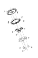
インターナルギア18は図5に示すように円環状をしており、その外周部にはラチェット歯18aが、内周部にはプラネタリギア16と噛合する内歯18bが設けられている。すなわち、プラネタリギア16は、サンギア13bとインターナルギア18の内歯18bに挟まれて、リダクションピン15を中心に自転が可能になっていると共に、キャリアギア14の中心(スプール4の軸心)の周りに公転が可能とされている。
【0024】
このように構成されたシートベルト巻取装置のスプール4とモータ8の動力伝達経路を入り切りするための機構として、係止レバー21と、コネクトギア11と一体に回転可能で係止レバー21を保持するレバースプリング22と、スプリング保持部材23が設けられている。
【0025】
図6に、この機構を詳細に示す。スプリング保持部材23の軸方向側面には軸方向に延びる3本の突出ピン23aが設けられており、これらの突出ピン23aがコネクトギア11の3個の軸方向孔11cそれぞれ嵌合されることで、スプリング保持部材23がコネクトギア11に組み付けられる。また、スプリング保持部材23の外周面には、径方向に延びる3個の突起23bが周方向に等間隔に設けられている。そして、レバースプリング22が、その湾曲部22aがスプリング保持部材23の外周に位置するようにして配置されるとともに、この湾曲部22aがスプリング保持部材23の2個の突起23bとコネクトギア11との間に、回転方向に所定の摩擦を有して扶持されることでスプリング保持部材23に組み付けられる。
【0026】
また、係止レバー21は第2リテーナ9に設けられた溝に沿って平行移動し、平行移動によりインターナルギア18のラチェット歯18aに接離可能に設けられている。そして、係止レバー21は、その凹部21bに嵌まり込んだレバースプリング22によって、前記のように平行移動するように駆動される。
【0027】
以下、モータ8とスプール4間の動力伝達のメカニズムと、動力伝達の入り切りのメカニズムについて、図7〜図9を用いて説明する。
これらの図に示されるように、モータ8の回転はモータギア10から、コネクトギア11の歯11aを介してコネクトギア11に伝えられ、その歯11bと、中間減速ギア12の歯12aを介して中間減速ギア12に伝えられる。そして、中間減速ギア12の歯12bと減速ギア13の大径歯部13aを介して減速ギア13に伝達される。減速ギア13には、サンギア13bがその中心軸を同じにして一体に取り付けられている。よって、モータ8が回転すると、これらのギア群が一体となって回転する。
【0028】
一方、図4に示されるスプール4のスプライン軸4bには、前述のようにキャリアギア14の中心孔(スプライン孔)14cが嵌まり込んでいる。よって、スプール4が回転すると、キャリアギア14が一体に回転し、それにより3個のプラネタリギア16がスプール軸を中心として公転する。
【0029】
これら、モータ8に結合された動力伝達系と、スプール4に連結された動力伝達系の連結を入り切りするのが、インターナルギア18である。図7は、モータ8が回転していないときの様子を示す図である。このとき、レバースプリング22により、係止レバー21は、インターナルギア18のラチェット歯車18aとは係合しないような位置となっている。よって、インターナルギア18は完全にフリーな状態にあり、何の抵抗も受けずに回転できる。それに対し、サンギア13bと減速ギア13を回転させるためには、モータ8の回転抵抗に打ち勝たなければならない。
【0030】
このような状態で、スプール4がどちらかの方向に回転すると、プラネタリギア16が公転する。そのとき、インターナルギア18の抵抗がないので、プラネタリギア16は、自転しながらサンギア13aの周りを公転し、インターナルギア18を回転させる。すなわち、サンギア13aは回転しない。よって、スプール4は、モータ8の回転抵抗を受けずに回転することができる。従って、特に、人間がシートベルトを引き出すとき、大きな抵抗力を受けることなく引き出しが可能となる(巻き取り用ゼンマイの力に抗するのみでよい)。
【0031】
図8は、モータ8がシートベルト巻き取り方向に駆動されたときの様子を示す図である。すなわち、モータ8が図のCW方向に回転すると、コネクトギア11がCCW方向に減速されて回転する。すると、前述のようにレバースプリング22の湾曲部22aがスプリング保持部材23の突起23bとコネクトギア11との間に回転方向に所定の摩擦を有して保持されているので、このコネクトギア11のCCW方向の回転で、レバースプリング22も同方向に一緒に回転する。
【0032】
これにより、係止レバー21がインターナルギア18に接近する方向に平行移動して、係止爪21aがインターナルギア18のラチェット歯18aの外周に当接して係合可能な係合位置となる。係止爪21aがラチェット歯18aの外周に当接した後は、レバースプリング22はそれ以上CCW方向には回転できなくなる。しかし、コネクトギア11とレバースプリング22との間にすべりが生じてコネクトギア11がレバースプリング22に対して相対回転する。これにより、モータ8は回転を継続することができる。
【0033】
同時に、コネクトギア11の回転が中間減速ギア12を介して減速されて減速ギア13に伝達され、減速ギア13がCCW方向に回転するので、サンギア13bが同方向に減速ギア13と同速度で回転する。このサンギア13bの回転で各プラネタリギア16がCW方向に自転し、インターナルギア18がCW方向に回転する。このとき、インターナルギア18が回転するため、各プラネタリギア16は公転しない。
【0034】
インターナルギア18がCW方向に回転すると、ラチェット歯18aと係止爪21aとが互いに係合し、インターナルギア18の回転が停止する。
インターナルギア18の回転が停止すると、前述のようにモータ8の駆動トルクで各プラネタリギア16が自転しているので、各プラネタリギア16はインターナルギア18の内歯18bに沿って、サンギア13bのまわりをCCW方向に減速されて公転するようになる。
【0035】
したがって、プラネタリギア16を保持するキャリアギア14が、各プラネタリギア16の公転速度でCCW方向に回転するので、スプール4がシートベルト巻き取り方向に回転する。
【0036】
図9は、モータ8がシートベルト引き出し方向に回転したときの様子を示す図である。モータ8が図のCCW方向に回転すると、コネクトギア11がCW方向に減速されて回転する。すると、前述のようにレバースプリング22の湾曲部22aがスプリング保持部材23の突起23bとコネクトギア11との間に回転方向に所定の摩擦を有して保持されているので、このコネクトギア11のCW方向の回転で、レバースプリング22も同方向に一緒に回転する。これにより、係止レバー21がインターナルギア18から遠ざかる方向に平行移動して、係止爪21aとインターナルギア18のラチェット歯18aの係合が外れる。すると、インターナルギア18の回転が自由になる。
【0037】
図8に示したと同じように、モータ8の回転により減速ギア13とサンギア13aが駆動され、サンギア13aの回転がプラネタリギア16に伝わってプラネタリギア16を自転させる。しかし、インターナルギア18が回転抵抗無く回転するので、プラネタリギア16は公転を行うことが無く、従って、モータ8の回転はスプール4には伝達されない。
【0038】
以上をまとめると、モータが巻き取り方向に回転したときは、その回転力によって駆動される係止レバーによってインターナルギアの回転が止められ、それによりモータとスプールとの間の動力伝達経路が結合される。その他の場合は、係止レバーとインターナルギアとの係合が無く、インターナルギアは自由に回転できるので、モータとスプールとの間の動力伝達経路は切り離される。
【0039】
なお、以上の実施の形態においては、係止レバーの駆動をモータの動力を使用して行っていたが、例えばソレノイド等により電気的に駆動し、インターナルギアと係合させたり係合を解いたりするようにしてもよい。
【0040】
以下、以上のように構成された第1先願発明の実施の形態であるシートベルト巻取装置の作動の例について説明する。この実施の形態においては、通常の状態では、動力伝達経路切替機構により、モータとスプール間の動力伝達経路をオフとしておく。シートベルトの巻き取りは、ゼンマイばねによって行われる。よって、乗員は、シートベルトを引き出す際に、ゼンマイばねの巻き取り力に抗する引き出し力のみで、シートベルトを引き出すことができる。
【0041】
そして、衝突予測装置等より、衝突等の事故が発生する可能性のあることを示す信号が与えられたとき、シートベルト巻取制御装置が、モータをシートベルト巻き取り方向に駆動すると共に、動力伝達経路切替機構によりモータとスプール間の動力伝達経路を結合する。これは、前述の実施の形態では、モータを巻き取り方向に駆動することにより、自然に行われる。よって、スプールにモータの巻き取り力が伝達され、スプールによりシートベルトが巻き取られる。このシートベルトの巻き取りは、従来のように、実際に衝突が発生してから行われるのでなく、衝突が予測された時点から開始されるので、確実に乗員をシートに拘束することができる。
【0042】
衝突等の発生が実際に起こらなかった場合は、モータの駆動を停止すると共に、前記動力伝達切替機構(ラチェット機構)の結合を解除することにより、スプールの回転が自由になり、人間が容易にシートベルトを引き出すことが可能となる。
【0043】
なお、以上の第1先願発明の説明においては、図面が煩雑になるのを避けるため、あえて図に示された火薬式プリテンショナの図示を省略し、その説明も省略したが、火薬式プリテンショナが、図4における第2リテーナ9の右側に設置されており、その場合における火薬式プリテンショナの作動と役割は、図に示した従来技術と同じである。
【0044】
また、第1先願発明においては、この他に、シートベルトをモータで巻き取った場合に、スプールがシートベルトの巻き取り方向にのみ回転し、引き出し方向には回転しないようにする機構が付属されているが、本願発明にはこの機構は関係ないのでその図示と説明を省略する。
【0045】
しかしながら、先願発明において、火薬式プリテンショナを有するものにおいては、以下のような事象が発生する場合がある。
すなわち、従来技術においては、実際に衝突が起こって火薬式プリテンショナが作動し、乗員をシートに強力に拘束した後、火薬による力が消滅すると、シートベルトが引き出されるようになっていた。この際、前述した「フォースリミッタ機構」が働き、シートベルトはトーションバーの捩れ力による張力を受けながら引き出されるようにされていた。
【0046】
ところが、第1先願発明の実施の形態を例にとると、火薬式プリテンショナが作動しても、ラチェット歯18aと係止爪21aとが互いに係合したままとなり、インターナルギア18の回転が停止したままの状態に保たれる可能性があった。そのようなことが発生すると、実際に衝突が起こって火薬式プリテンショナが作動し、乗員をシートに強力に拘束した後、火薬による力が消滅し、シートベルトが引き出される際に、モータがスプールに機械的に結合された状態のままとなるので、モータがシートベルト引き出し力の負荷となる場合がある。
【0047】
このような事象の発生を防止するために、本発明者等は、火薬式プリテンショナが作動するとほとんど同時に、モータ逆転させることによって、ラチェット歯18aと係止爪21aの係合を解除し、モータとスプールの機械的な結合(クラッチ機構)を解放することにより、「フォースリミッタ機構」作動時にモータが引き出し力の負荷となることを防止する方法を発明し、特願2001−133967号として特許出願した(以下、「第2先願発明」という)。この方法は、電気的にモータとスプールの機械的な結合を解放するものである。
【0048】
本発明は第2先願発明と目的を同じくするものであり、火薬式プリテンショナが作動した場合に、電気的手段を用いることなく、メカニズムにより、モータとスプールの機械的な結合(クラッチ機構)を解放することによって、「フォースリミッタ機構」を安定して作動させることができるシートベルト巻取装置を提供することを課題とする。
【0049】
【課題を解決するための手段】
前記課題を解決するための第1の手段は、モータによりシートベルトを巻き取る機構を有するシートベルト巻取装置であり、前記モータとシートベルトが巻回されたスプールと、結合時には前記スプールをシートベルト巻き取り方向にのみ回転させ、非結合時には前記スプールのいずれの方向への回転をも許容する動力伝達切替機構とを有してなり、かつ、シートベルトを急激に引き出すような力が働いたとき、シートベルトが巻き付けられているスプールのシートベルト引き出し方向への回転をトーションバーによる捩れ力に抗して行わせるフォースリミッタ機構と、衝突が検知されたときシートベルトを強制的に巻き取る火薬式プリテンショナを有するものであって、前記火薬式プリテンショナが作動したときに移動する火薬式プリテンショナの機構部の動きにより、前記動力伝達切替機構が非結合状態とされ、前記モータと前記スプールの機械的な結合が外れるようにされていることを特徴とするシートベルト巻取装置(請求項1)である。
【0050】
本手段においては、火薬式プリテンショナが作動したときに移動する火薬式プリテンショナの機構部の動きにより、前記動力伝達切替機構が非結合状態とされ、前記モータと前記スプールの機械的な結合が外れるようにされている(本明細書において、動力伝達切替機構が非結合状態とされているとは、モータとスプールとの機械的な動力伝達が働かないようにされていることであり、動力伝達切替機構が結合状態とされているとは、モータとスプールとの機械的な動力伝達が働くようにされていることである)。よって、火薬的プリテンショナが作動したとき、メカニズムのみにより、モータと前記スプールの機械的な結合を切り離し、その後に発生する「フォースリミッタ機構」作動時にモータが負荷となることを防止することができる。
【0051】
前記課題を解決するための第2の手段は、前記第1の手段であって、前記動力伝達切替機構はラチェット歯車を有し、前記モータのシートベルト巻き取り方向への回転力により駆動される係止部と前記ラチェット歯車との噛み合いの有無により、結合状態と非結合状態が切り替わるものであり、前記係止部は、火薬式プリテンショナが作動したときに移動する火薬式プリテンショナの機構部の動きにより、前記ラチェット歯車との係合を解除されるようにされていることを特徴とするもの(請求項2)である。
【0052】
本手段においては、動力伝達切替機構の結合、非結合が、モータの回転力で駆動される係止部とラチェット歯車の係合により行われるようになっており、かつ、前記係止部は、火薬式プリテンショナが作動したときに移動する火薬式プリテンショナの機構部の動きにより、前記ラチェット歯車との係合を解除されるようにされているので、構造が簡単になる。
【0053】
前記課題を解決するための第3の手段は、前記第2の手段であって、前記モータの回転トルクで前記回動可能な制御レバーを備えており、当該制御レバーが前記係止部を駆動することにより係止部と前記ラチェット歯車との噛み合いが制御されるようにされていることを特徴とするもの(請求項3)である。
【0054】
本手段においては、モータが巻き取り方向に回転すると、そのトルクにより制御レバーが回動し、それにより係止部と前記ラチェット歯車とを噛み合わせて、モータとスプール間の動力の伝達を可能にする。モータが回転していない場合には、制御レバーは初期位置にあり、係止部と前記ラチェット歯車とを噛み合わせないので、モータとスプールは動力的に切り離され、スプールは自由に回転可能となる。よって、簡単な構成により、モータとスプール間の動力の伝達のオン・オフが可能となる。
【0055】
前記課題を解決するための第4の手段は、前記第2の手段又は前記第3の手段であって、前記モータの回転を減速して前記スプールに伝達する減速機構を備えており、この減速機構は、モータの回転が伝達されるサンギアと、回転可能に設けられ、外周にラチェット歯を有しかつ内周に内歯を有するリング状のインターナルギアと、これらのサンギアとインターナルギアとに噛合するプラネタリギアと、このプラネタリギアを自転可能に支持するとともにその公転を前記スプールに伝達するキャリヤとを有し、また、前記動力伝達切替機構は、更に、前記ラチェット歯に係合しない非係合位置と前記ラチェット歯に係合可能な係合位置との間で回動可能な係止レバーを備えており、前記制御レバーが回動しない通常時は前記係止レバーを非係合位置に設定して前記インターナルギアの回転を自由にし、前記制御レバーが回動したときは前記係止レバーを係合位置に設定して、前記ラチェット歯に前記係止レバーが係合することで前記インターナルギアの回転を禁止するようになっており、前記インターナルギアの回転が禁止されたときは、前記動力伝達切替機構が結合状態に設定され、前記インターナルギアの回転が自由であるときは、前記動力伝達切替機構が非結合状態に設定されるようになっていることを特徴とするもの(請求項4)である。
【0056】
本手段においては、係止レバーがラチェット歯に係合していないときは、インターナルギアは無負荷に近い状態で回転可能となっている。この状態でモータが回転すると、それによりサンギアが回転される。すると、インターナルギアが無負荷に近い状態で回転可能であり、一方、プラネタリギアの公転はスプールの負荷を受けているので、各プラネタリギアは公転せず自転して、インターナルギアを回転させる。よって、モータの動力はスプールには伝達されない。
【0057】
この状態でスプールが回転すると、プラネタリギアは公転するが、サンギアにはモータの負荷がかかっているのに対し、インターナルギアは無負荷であるので、サンギアを回転させず、インターナルギアを回転させながら公転する。よって、スプールとモータの動力伝達は切られているので、シートベルトの引き出し、巻き取りは、モータの負荷をうけることなく自由に行われる。
【0058】
係止レバーがラチェット歯に係合すると、インターナルギアの回転が阻止される。この状態でモータが回転すると、それにより減速ギアとサンギアが回転される。すると、インターナルギアが回転できないので、プラネタリギアはサンギアによって自転させられると共に、インターナルギアによって公転力を受け公転する。よって、プラネタリギアに結合されているスプールが駆動力を受けて回転する。このときは、スプールが回転した場合も、プラネタリギアの公転によってサンギアが回転力を受け、モータが回転力を受ける。すなわち、モータとスプールの間の動力伝達経路が結合されていることになる。
【0059】
前記課題を解決するための第5の手段は、前記第2の手段又は前記第3の手段であって、前記モータの回転を減速して前記スプールに伝達する減速機構を備えており、この減速機構は、その回転をスプールに伝達するサンギアと、回転可能に設けられ、外周にラチェット歯を有しかつ内周に内歯を有するリング状のインターナルギアと、これらのサンギアとインターナルギアとに噛合するプラネタリギアと、このプラネタリギアを自転可能に支持するとともに前記モータの回転により前記プラネタリギアを公転させるキャリヤとを有し、また、前記動力伝達切替機構は、更に、前記ラチェット歯に係合しない非係合位置と前記ラチェット歯に係合可能な係合位置との間で回転可能な係止レバーを備えており、前記制御レバーが回動しない通常時は前記係止レバーを非係合位置に設定して前記インターナルギアの回転を自由にし、前記制御レバーが回動したときは前記係止レバーを係合位置に設定して、前記ラチェット歯に前記係止レバーが係合することで前記インターナルギアの回転を禁止するようになっており、前記インターナルギアの回転が自由であるときは、前記動力伝達切替機構が非結合状態に設定され、前記インターナルギアの回転が禁止されたときは、前記動力伝達切替機構が結合状態に設定されるようになっていることを特徴とするもの(請求項5)である。
【0060】
本手段においては、サンギアがスプール側に結合され、プラネタリギア側がモータ側に結合されている点が前記第4の手段と異なるだけであり、その作動は前記第4の手段と同じである。よって、前記第4の手段と同じ作用効果を奏する。
【0061】
前記課題を解決するための第6の手段は、前記第2の手段から第5の手段のいずれかであって、火薬プリテンショナが作動したときに火薬の力を直接又は間接的に受けて回転し、その回転力をスプールに伝える回転体の動きを直接的又は間接的に利用することにより、前記係止部の、前記ラチェット歯車との係合を解除するものであることを特徴とするもの(請求項6)である。
【0062】
通常の火薬プリテンショナには、その作動時に、火薬の力を直接又は間接的に受けて回転し、その回転力をスプールに伝える回転体が存在する。本手段においては、この回転体の動きを直接的又は間接的に利用することにより、前記係止部の、前記ラチェット歯車との係合を解除するようにしているので、構成が簡単になる。
【0063】
前記課題を解決するための第7の手段は、前記第6の手段であって、火薬プリテンショナは、火薬の力をパイプ中に入れられたボールに伝達し、ボールの力を歯車の外歯に伝えることより歯車を回転させてその回転力をスプールに伝えるものであり、定常状態においては当該歯車の外歯によってその形状を決められ、前記歯車が回転するとスプリング力により異なった形状となる第1の弾性体と、定常状態においては第1の弾性体によってその形状を決められ、第1の弾性体が前記異なった形状となったとき、スプリング力により異なった形状となる第2の弾性体を有し、第2の弾性体が異なった形状となるときの付勢力により、前記係止部の、前記ラチェット歯車との係合を解除するものであることを特徴とするもの(請求項7)である。
【0064】
本手段の作用については、後に実施の形態を例として詳細に説明する。
【0065】
【発明の実施の形態】
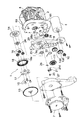
以下、本発明の実施の形態の例を、図を用いて説明する。図1は、本発明の実施の形態の1例であるシートベルト巻取装置の本発明に関する要部を示す分解斜視図である。以下の図においては、前出の図に示された構成要素と同じ構成要素には原則的に同じ符号を付している。しかし、部品の設置位置や構成、形状が図4と少し変わっており、かつ、図10と同じように火薬プリテンショナが設けられ、プリテンショナカバー61とパイプ63が図示されている。この火薬プリテンショナは、図10で説明したものと同じである。
【0066】
以下、図1に示される実施の形態について、図4と異なる点を中心に説明する。モータ5の出力は、モータギア10から、2つの中間減速ギア12c、12dを介してコネクトギア11に伝えられる。コネクトギア11の、図で裏側になっていて図示されない軸部にはレバースプリング22が巻き付けてあり、コネクトギア11と共に回転するようになっている。しかしながら、レバースプリング22の回転を阻止するような一定以上の力が働くと、その力が、レバースプリング22がコネクトギア11に巻き付いているバネ力に打ち勝ち、レバースプリング22はその位置で停止し、コネクトギア11との間で相対回転が可能とされるようになっている。
【0067】
図4の係止レバー21に相当するクラッチパウル21は、クラッチパウルピン25により、第2リテーナ9に固定されているが、クラッチパウル21と第2リテーナ9の間にはスプリング26が配置され、クラッチパウル21が、インターナルギア18のラチェット歯車18aから離れるように、クラッチパウル21を付勢している。
【0068】
モータがシートベルト巻き取り方向に回転すると、レバースプリング22がコネクトギア11と共に図の反時計方向に回転し、後に詳しく説明するように、それにより、クラッチパウル21を図の時計方向に回転させる。すると、クラッチパウル21がインターナルギア18のラチェット歯車18aに係合し、インターナルギア18の回転を止める。
【0069】
このようにすると、モータの回転力が、スプール4に伝達されるようになるメカニズムは図4〜図9において説明したものと同じである。ただし、図1に示す実施の形態においては、リテーナベアリング23とキャリアベアリング24が設けられているが、これは本発明と直接の関係はない。また、図4〜図9においては、キャリアギア14には、その外周にラチェット歯が設けられているが、本実施の形態の図1においては、設けられておらず、単なるキャリア14となっているが、これは本発明と直接の関係はない。
【0070】
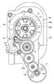
このように、図1に示す実施の形態では、インターナルギア11を停止させる機構が図4と異なっているので、図2により、さらに詳しく説明する。図2において、クラッチパウル21は第2リテーナ9に、クラッチパウルピン25により固定されており、クラッチパウルピン25の周りに回動可能とされている。クラッチパウル21は穴21dを有しており、この穴の中にレバースプリング22の折れ曲がった先端部22bが嵌り込んでいる。そして、クラッチパウル21は、一部が見えているスプリング26により、図の時計回りに付勢されており、通常は、インターナルギア18のラチェット歯18aから離れている。
【0071】
モータ5がシートベルト巻き取り方向に回転すると、インターナルギア11は時計方向に回転し、これに伴い、レバースプリング22が時計方向に回動する。すると、レバースプリング22の先端部22bが穴21dの縁に当たり、スプリング26の付勢力に逆らって、クラッチパウル21を反時計回りに回動させる。すると、クラッチパウル21の先端部がインターナルギア18のラチェット歯18aに係合し、インターナルギア18の回転を止める。
【0072】
モータ5がシートベルト引き出し方向に回転すると、インターナルギア11は反時計方向に回転し、これに伴い、レバースプリング22が反時計方向に回動する。すると、レバースプリング22の先端部22bが穴21dの縁に当たり、スプリング26の付勢力と協働して、クラッチパウル21を時計回りに回動させる。すると、クラッチパウル21の先端部がインターナルギア18のラチェット歯18aから離れて、インターナルギア18の回転が自由となる。
【0073】
また、本実施の形態においては、火薬プリテンショナが作動したとき、クラッチパウル21をインターナルギア18のラチェット歯18aから引き離すための機構として、ストッパ28とリリーススプリング29が図1の第2リテーナ9とプリテンショナカバー61の間に設けられている。
【0074】
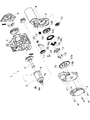
以下、火薬プリテンショナが作動したときの動きを、図1〜図3を参照しながら説明する。図3は、火薬プリテンショナの作動に伴って作用する主要部の部品の構成を示したもので、説明に関係のない部品の図示を省略している。また、図3は、図1における第2リテーナ9とプリテンショナカバー61の間にある部品を中心に示したもので、これらを実線で、図1においてプリテンショナカバー61の奥(右側)にある部品を破線で、第2リテーナ9より手前(左側)にある部品を2点鎖線で示している。
【0075】
図3において、バネ体であるストッパ28が凸部32に巻き付けられてプリテンショナカバー61に固定されており、その先端部28aは図1に示すように折れ曲がり、プリテンショナカバー61に設けられた弧状の長穴61aを貫通して、リングギア70(図10に示すものと同じもの)の外歯71aの片面に当接している。この状態でストッパ28はその付勢力に対して押し縮められたようになっており、リングギア70の外歯71aが、ストッパ28が広がるのを妨げている。
【0076】
このストッパ28の先端部28aに、リリーススプリング29の先端部が支えられている。リリースプリング29は、板バネ部材で構成されており、プリテンショナカバー61の凸部30、31に挟み込まれて固定されている。すなわち、ストッパ28の折れ曲がった先端部28aの先端部は、前述のようにリングギア70の外歯71aに当接しており、ストッパ28の先端部28aの根本部には、リリースプリング29が乗り上げるような形となっている。リリーススプリング29は、図3で時計回りに付勢されているが、ストッパ28の先端部28aのために、付勢力に抗して弾性的に曲げられた状態で固定されている。
【0077】
図10において説明したように、火薬プリテンショナが作動すると、リングギア70がフリーとなり、ピニオン72と係合する。そして、その状態でボール67に押されてリングギア70が回転し、ピニオン72を介してスプール42を回転させる。
【0078】
このとき、リングギア70は、図3において反時計回りに回転する。すると、ストッパ28の先端部28aを固定していた外歯70aが移動し、ストッパ28の先端部がフリーとなる。するとストッパ28は、その付勢力により開き、先端部28aが長穴61aの他端にくるまで移動し、図の28’のようになる。先端部は28a’の位置まで移動する(28’、28a’のように、最初の位置から動くものは、第2リテーナ9とプリテンショナカバー61の間にある部品であっても、動いた後の位置を2点鎖線で記述する)。
【0079】
すると、リリーススプリング29は、ストッパ28の拘束を受けなくなり、その付勢力により、図3の時計回りに回動する。図1に示されるように、クラッチパウル21は、ピン部21cを有し、このピン部21cは、第2リテーナ9に設けられた穴9aを貫通して、リリーススプリング29の位置まで達している。
【0080】
リリースプリング29が図3の時計回りに回動すると、リリーススプリング29がこのピン部21cに当接し、ピン部21cを押し下げる。この力は、レバースプリング22の力より大きくされている。よって、クラッチパウル21は、クラッチパウルピン25の周りに、図3で時計回りに回動し、図3の21’の位置となって、クラッチパウル21の先端部がインターナルギア18のラチェット歯18aから離れて、インターナルギア18の回転が自由となる。そのとき、リリーススプリングは29’で示される位置、クラッチパウルのピン部は21c’で示される位置となる。
【0081】
インターナルギア18の回転が自由となれば、モータ8とスプール4間の機械的な結合が切り離されるのは、前述の通りであるので、モータの負荷が「フォースリミッタ機構」に影響を及ぼすことはない。
【0082】
【発明の効果】
以上説明したように、本発明によれば、メカニズムにより、火薬式プリテンショナが作動した場合に、「フォースリミッタ機構」の性能を安定して発揮させることができるシートベルト巻取装置を提供することができる。
【図面の簡単な説明】
【図1】 本発明の実施の形態の1例であるシートベルト巻取装置の本発明に関する要部を示す分解斜視図である。
【図2】 図1における、インターナルギアを停止させる機構を詳細に示す図である。
【図3】 火薬プリテンショナの作動に伴って作用する主要部の部品の構成を示す図である。
【図4】 第1先願発明の実施の形態の1例であるシートベルト巻取装置の概要を示す分解斜視図である。
【図5】 図4に示す実施の形態における動力伝達経路切替機構の要部を示す概要図である。
【図6】 図4に示す実施の形態における動力伝達経路切替機構の要部を示す概要図である。
【図7】 図4に示す実施の形態における動力伝達経路切替機構の作動を説明する図である。
【図8】 図4に示す実施の形態における動力伝達経路切替機構の作動を説明する図である。
【図9】 図4に示す実施の形態における動力伝達経路切替機構の作動を説明する図である。
【図10】 従来のシートベルト巻取装置の概要を示す図である。
【符号の説明】
1…シートベルト巻取装置、2…フレーム、4…スプール、4a…スプール軸、4b…スプライン軸、5…トーションバー、6…リテーナ、7…ゼンマイユニット、8…モータ、9…第2リテーナ、9a…長穴、9b…長穴、9c…案内部、10…モータギア、11…コネクトギア、11a…歯、11b…歯、11c…軸方向孔、12…中間減速ギア、12a…歯、12b…歯、12c…中間減速ギア、12d…中間減速ギア、13…減速ギア、13a…大径歯部、13b…サンギア、14…キャリア(キャリアギア)、14c…中心穴、14d…ネジ穴、15…リダクションピン、16…プラネタリギア、17…リダクションプレート、18…インターナルギア、18a…ラチェット歯、18b…内歯、21…係止レバー(クラッチパウル)、21a…係止爪、21b…凹部、22…レバースプリング、22a…湾曲部、22b…先端部、25…クラッチパウルピン、26…スプリング、27…カバー、28…ストッパ、28a…先端部、29…リリーススプリング、30…凸部、31…凸部、32…凸部、61…プリテンショナカバー、61a…長穴、63…パイプ、70…リングギア[0001]
BACKGROUND OF THE INVENTION
The present invention relates to a method for controlling a seat belt retractor having a function of winding a seat belt with a motor.
[0002]
[Prior art]
Seat belt retractors are required to be attached to ensure the safety of passengers in the event of an accident such as a passenger car collision, and various types of seat belt retractors have been developed. An example of the simplest configuration is shown in FIG.
[0003]
The
[0004]
A concave fitting portion (not shown) is provided inside the
[0005]
By such a mechanism, the
[0006]
Among these components, the locking
[0007]
When the seat belt is pulled out in a normal state, there is nothing that can resist the rotation of the
[0008]
Even if the
[0009]
When a sudden withdrawal of the seat belt occurs due to a collision or the like, the
[0010]
Then, the locking
[0011]
Accordingly, the rotation of the
[0012]
The above description shows an outline of the seat belt retractor. For example, a complicated mechanism is used as a mechanism for stopping the rotation of the
[0013]
The seat belt retractor shown in FIG. 10 is accompanied by a seat belt retracting device called an explosive pretensioner in addition to the mechanism as described above. In this case, when a collision or the like actually occurs, the seat belt is wound up rapidly and strongly by the power of the explosive to restrain the occupant to the seat.
[0014]
Hereinafter, the configuration of the explosive pretensioner will be described. A
[0015]
The
[0016]
On the other hand, in the
[0017]
[Problems to be solved by the invention]
The inventors have improved such a conventional seat belt winding device, and before an accident such as a collision actually occurs, at the stage where these occurrences are expected, the seat belt is wound by a motor, The invention of a seat belt retractor having a function of removing slack of the belt and restraining the occupant to the seat belt with a certain force was invented, and a patent application was filed as Japanese Patent Application No. 2001-12886 (hereinafter referred to as “first prior invention”). ").
[0018]
This is a seat belt winding device having a mechanism for winding a seat belt by a motor, and when the motor and the seat belt are wound together, the spool is rotated only in the seat belt winding direction when coupled, A power transmission switching mechanism (ratchet mechanism) that allows the spool to rotate in any direction when not coupled.
[0019]
Hereinafter, an example of an embodiment of the first prior invention will be described with reference to the drawings. FIG. 4 is an exploded perspective view showing an outline of a seat belt retractor as an example of an embodiment of the first prior invention. In the embodiment shown in FIG. 4, a lock mechanism, a force limiter mechanism, and a spring (not shown) for winding the spool are provided as shown in FIG. Since there is no description, explanation is omitted.
[0020]
As shown in FIG. 4, in the seat belt retractor 1, a spool 4 that winds up the
[0021]
The
[0022]
A center hole (spline hole) 14 c of the
[0023]
As shown in FIG. 5, the
[0024]
As a mechanism for turning on and off the power transmission path of the spool 4 and the
[0025]
FIG. 6 shows this mechanism in detail. Three projecting
[0026]
The locking
[0027]
Hereinafter, the power transmission mechanism between the
As shown in these drawings, the rotation of the
[0028]
On the other hand, the center hole (spline hole) 14c of the
[0029]
It is the
[0030]
In such a state, when the spool 4 rotates in either direction, the
[0031]
FIG. 8 is a diagram illustrating a state in which the
[0032]
As a result, the locking
[0033]
At the same time, the rotation of the
[0034]
When the
When the rotation of the
[0035]
Therefore, since the
[0036]
FIG. 9 is a diagram illustrating a state where the
[0037]
As shown in FIG. 8, the
[0038]
In summary, when the motor rotates in the winding direction, the rotation of the internal gear is stopped by the locking lever driven by the rotational force, thereby coupling the power transmission path between the motor and the spool. The In other cases, there is no engagement between the locking lever and the internal gear, and the internal gear can freely rotate, so that the power transmission path between the motor and the spool is disconnected.
[0039]
In the above embodiment, the locking lever is driven using the power of the motor. However, for example, the locking lever is electrically driven by a solenoid or the like to engage or disengage the internal gear. You may make it do.
[0040]
Hereinafter, an example of the operation of the seat belt retractor which is the embodiment of the first prior invention having the above-described configuration will be described. In this embodiment, in a normal state, the power transmission path between the motor and the spool is turned off by the power transmission path switching mechanism. The seat belt is wound up by a spring. Therefore, when the seat belt is pulled out, the occupant can pull out the seat belt only with a pulling force that resists the winding force of the mainspring spring.
[0041]
When a signal indicating that an accident such as a collision may occur from the collision prediction device or the like, the seat belt winding control device drives the motor in the seat belt winding direction, A power transmission path between the motor and the spool is coupled by a transmission path switching mechanism. In the above-described embodiment, this is naturally performed by driving the motor in the winding direction. Therefore, the winding force of the motor is transmitted to the spool, and the seat belt is wound by the spool. The seat belt winding is not performed after a collision actually occurs as in the prior art, but is started at the time when the collision is predicted, so that the occupant can be reliably restrained to the seat.
[0042]
When the occurrence of a collision or the like does not actually occur, the motor is stopped and the coupling of the power transmission switching mechanism (ratchet mechanism) is released, so that the rotation of the spool becomes free and humans can easily The seat belt can be pulled out.
[0043]
In the description of the invention of the first prior application, the explosive pretensioner is not shown in the drawing and the explanation thereof is also omitted to avoid complication of the drawing. The tensioner is installed on the right side of the
[0044]
In addition, in the invention of the first prior application, in addition to this, when the seat belt is wound by a motor, a mechanism for preventing the spool from rotating only in the seat belt winding direction and not in the pulling direction is attached. However, since this mechanism is not related to the present invention, its illustration and description are omitted.
[0045]
However, in the invention of the prior application, the following event may occur in the case of having the explosive pretensioner.
That is, in the prior art, after a collision actually occurs and the explosive pretensioner operates to strongly restrain the occupant to the seat, the seat belt is pulled out when the force due to the explosive disappears. At this time, the above-mentioned “force limiter mechanism” works, and the seat belt is pulled out while receiving the tension due to the torsional force of the torsion bar.
[0046]
However, taking the embodiment of the first prior invention as an example, even if the explosive pretensioner operates, the
[0047]
In order to prevent the occurrence of such an event, the present inventors have released the engagement between the
[0048]
The present invention has the same object as the invention of the second prior application, and when the explosive pretensioner is operated, the motor and the spool are mechanically coupled (clutch mechanism) by a mechanism without using electrical means. It is an object of the present invention to provide a seat belt retractor that can stably operate the “force limiter mechanism” by releasing
[0049]
[Means for Solving the Problems]
A first means for solving the above-mentioned problem is a seat belt winding device having a mechanism for winding a seat belt by a motor. The motor and a spool around which the seat belt is wound, and the spool is seated when coupled. It has a power transmission switching mechanism that rotates only in the belt winding direction and allows rotation of the spool in any direction when not coupled, and has a force that pulls out the seat belt rapidly. A force limiter mechanism that rotates the spool around which the seat belt is wound in the seat belt pull-out direction against the torsional force of the torsion bar, and explosive that forcibly winds up the seat belt when a collision is detected An explosive pretensioner having a pretensioner that moves when the explosive pretensioner is activated A seat belt retractor (not shown), wherein the power transmission switching mechanism is brought into a non-coupled state by movement of a mechanism portion of the jointer, and the mechanical coupling between the motor and the spool is released. Item 1).
[0050]
In this means, the power transmission switching mechanism is disengaged by the movement of the mechanism part of the explosive pretensioner that moves when the explosive pretensioner is operated, and the motor and the spool are mechanically coupled. (In this specification, the power transmission switching mechanism is in a non-coupled state means that the mechanical power transmission between the motor and the spool is prevented from acting. The fact that the transmission switching mechanism is in the coupled state means that mechanical power transmission between the motor and the spool is performed). Therefore, when the explosive pretensioner is activated, the mechanical connection between the motor and the spool is disconnected only by the mechanism, and it is possible to prevent the motor from becoming a load during the operation of the “force limiter mechanism” generated thereafter. .
[0051]
The second means for solving the problem is the first means, wherein the power transmission switching mechanism has a ratchet gear, and is driven by a rotational force of the motor in the seat belt winding direction. A coupling state and a non-coupling state are switched depending on whether or not the locking portion and the ratchet gear are engaged, and the locking portion moves when the explosive pretensioner operates. The engagement with the ratchet gear is released by the movement of (2).
[0052]
In this means, coupling and non-coupling of the power transmission switching mechanism are performed by engagement of a latching portion driven by the rotational force of the motor and a ratchet gear, and the latching portion is Since the engagement with the ratchet gear is released by the movement of the mechanism part of the explosive pretensioner that moves when the explosive pretensioner is actuated, the structure is simplified.
[0053]
The third means for solving the problem is the second means, and includes the control lever that can be rotated by the rotational torque of the motor, and the control lever drives the locking portion. By doing so, the meshing between the locking portion and the ratchet gear is controlled (claim 3).
[0054]
In this means, when the motor rotates in the winding direction, the control lever is rotated by the torque, thereby engaging the locking portion and the ratchet gear, thereby enabling transmission of power between the motor and the spool. To do. When the motor is not rotating, the control lever is in the initial position and does not mesh the locking portion with the ratchet gear, so that the motor and the spool are powered off and the spool can freely rotate. . Therefore, transmission of power between the motor and the spool can be turned on / off with a simple configuration.
[0055]
A fourth means for solving the problem is the second means or the third means, and includes a speed reduction mechanism that reduces the rotation of the motor and transmits it to the spool. The mechanism is meshed with a sun gear that transmits the rotation of the motor, a ring-shaped internal gear that is provided rotatably and has ratchet teeth on the outer periphery and inner teeth on the inner periphery, and these sun gear and internal gear. And a carrier for supporting the planetary gear so as to rotate and transmitting the revolution to the spool, and the power transmission switching mechanism further disengages not engaged with the ratchet teeth. A locking lever that can be rotated between a position and an engagement position that can be engaged with the ratchet teeth, and the locking lever is not engaged during normal times when the control lever does not rotate. The internal gear is set free to rotate, and when the control lever is rotated, the locking lever is set to the engagement position, and the locking lever is engaged with the ratchet teeth. When the rotation of the internal gear is prohibited, and when the rotation of the internal gear is prohibited, the power transmission switching mechanism is set in a coupled state, and when the rotation of the internal gear is free, The power transmission switching mechanism is set to a non-coupled state (claim 4).
[0056]
In this means, when the locking lever is not engaged with the ratchet teeth, the internal gear can rotate in a state close to no load. When the motor rotates in this state, the sun gear is thereby rotated. Then, the internal gear can rotate in a state close to no load. On the other hand, since the revolution of the planetary gear receives the load of the spool, each planetary gear rotates without rotating and rotates the internal gear. Therefore, the motor power is not transmitted to the spool.
[0057]
When the spool rotates in this state, the planetary gear revolves, but the sun gear is loaded with the motor, while the internal gear is unloaded, so the sun gear is not rotated and the internal gear is rotated. Revolve. Therefore, since the power transmission between the spool and the motor is cut off, the seat belt can be pulled out and taken up freely without being subjected to the load on the motor.
[0058]
When the locking lever engages with the ratchet teeth, the internal gear is prevented from rotating. When the motor rotates in this state, the reduction gear and the sun gear are thereby rotated. Then, since the internal gear cannot rotate, the planetary gear is rotated by the sun gear and revolved by the revolving force by the internal gear. Therefore, Planetary A spool coupled to the gear receives a driving force and rotates. At this time, even if the spool rotates, Planetary The sun gear receives the rotational force due to the revolution of the gear, and the motor receives the rotational force. That is, the power transmission path between the motor and the spool is coupled.
[0059]
A fifth means for solving the above-described problem is the second means or the third means, and includes a speed reduction mechanism that reduces the rotation of the motor and transmits it to the spool. The mechanism is engaged with a sun gear that transmits the rotation to the spool, a ring-shaped internal gear that is provided rotatably and has ratchet teeth on the outer periphery and inner teeth on the inner periphery, and the sun gear and the internal gear. A planetary gear and a carrier that revolves the planetary gear by rotation of the motor and supports the planetary gear so as to rotate, and the power transmission switching mechanism further does not engage with the ratchet teeth. A locking lever that can rotate between a non-engagement position and an engagement position that can be engaged with the ratchet teeth is provided, and the control lever does not rotate normally. Sets the locking lever to the non-engagement position to freely rotate the internal gear, and when the control lever rotates, sets the locking lever to the engagement position, and the ratchet teeth When the locking lever is engaged, rotation of the internal gear is prohibited, and when the internal gear is free to rotate, the power transmission switching mechanism is set in a non-coupled state, and the internal gear is When the rotation of the gear is prohibited, the power transmission switching mechanism is set in a coupled state (claim 5).
[0060]
This means is different from the fourth means in that the sun gear is coupled to the spool side and the planetary gear side is coupled to the motor side, and the operation thereof is the same as the fourth means. Therefore, the same effect as the fourth means is achieved.
[0061]
A sixth means for solving the problem is any one of the second to fifth means, wherein the gunpowder pretensioner is actuated to receive direct or indirect force and rotate. The engagement of the locking portion with the ratchet gear is released by directly or indirectly utilizing the movement of the rotating body that transmits the rotational force to the spool. (Claim 6).
[0062]
A normal explosive pretensioner has a rotating body that rotates directly upon receiving the force of the explosive directly or indirectly and transmits the rotational force to the spool. In this means, since the engagement of the locking portion with the ratchet gear is released by using the movement of the rotating body directly or indirectly, the configuration is simplified.
[0063]
A seventh means for solving the above-mentioned problem is the sixth means, wherein the gunpowder pretensioner transmits the power of the gunpowder to the ball placed in the pipe, and the ball force is transmitted to the external teeth of the gear. Is transmitted to the spool, and the rotational force is transmitted to the spool. In a steady state, the shape is determined by the external teeth of the gear, and when the gear rotates, the shape changes depending on the spring force. The first elastic body and the second elastic body, whose shape is determined by the first elastic body in a steady state, and having a different shape due to the spring force when the first elastic body has the different shape. The engaging portion is disengaged from the ratchet gear by an urging force when the second elastic body has a different shape (claim 7). ).
[0064]
The operation of this means will be described in detail later by taking an embodiment as an example.
[0065]
DETAILED DESCRIPTION OF THE INVENTION
Hereinafter, an example of an embodiment of the present invention will be described with reference to the drawings. FIG. 1 is an exploded perspective view showing a main part related to the present invention of a seat belt retractor as an example of an embodiment of the present invention. In the following drawings, the same components as those shown in the previous drawings are in principle given the same reference numerals. However, the installation position, configuration, and shape of the parts are slightly different from those in FIG. 4, and an explosive pretensioner is provided as in FIG. 10, and the
[0066]
In the following, the embodiment shown in FIG. 1 will be described focusing on differences from FIG. The output of the
[0067]
The
[0068]
When the motor rotates in the seat belt retracting direction, the
[0069]
In this way, the mechanism by which the rotational force of the motor is transmitted to the spool 4 is the same as that described with reference to FIGS. However, in the embodiment shown in FIG. 1, the
[0070]
As described above, in the embodiment shown in FIG. 1, the mechanism for stopping the
[0071]
When the
[0072]
When the
[0073]
Further, in the present embodiment, when the gunpowder pretensioner is operated, as a mechanism for pulling the
[0074]
Hereinafter, the movement when the gunpowder pretensioner operates will be described with reference to FIGS. FIG. 3 shows the structure of the main parts that act in association with the operation of the explosive pretensioner, and illustrations of parts not related to the description are omitted. FIG. 3 mainly shows parts between the
[0075]
In FIG. 3, a
[0076]
The distal end portion of the
[0077]
As described with reference to FIG. 10, when the explosive pretensioner operates, the
[0078]
At this time, the
[0079]
Then, the
[0080]
When the release pull 29 rotates clockwise in FIG. 3, the
[0081]
If the
[0082]
【The invention's effect】
As described above, according to the present invention, when a gunpowder type pretensioner is operated by a mechanism, a seat belt retractor capable of stably exhibiting the performance of a “force limiter mechanism” is provided. Can do.
[Brief description of the drawings]
FIG. 1 is an exploded perspective view showing a main part related to the present invention of a seat belt retractor as an example of an embodiment of the present invention.
FIG. 2 is a diagram showing in detail a mechanism for stopping an internal gear in FIG. 1;
FIG. 3 is a diagram showing a configuration of a main part that acts in accordance with the operation of the explosive pretensioner.
FIG. 4 is an exploded perspective view showing an outline of a seat belt retractor as an example of an embodiment of the first prior invention.
FIG. 5 is a schematic diagram showing a main part of a power transmission path switching mechanism in the embodiment shown in FIG. 4;
6 is a schematic diagram showing a main part of a power transmission path switching mechanism in the embodiment shown in FIG.
7 is a diagram for explaining the operation of the power transmission path switching mechanism in the embodiment shown in FIG. 4; FIG.
FIG. 8 is a diagram for explaining the operation of the power transmission path switching mechanism in the embodiment shown in FIG. 4;
FIG. 9 is a diagram for explaining the operation of the power transmission path switching mechanism in the embodiment shown in FIG. 4;
FIG. 10 is a view showing an outline of a conventional seat belt retractor.
[Explanation of symbols]
DESCRIPTION OF SYMBOLS 1 ... Seat belt winding device, 2 ... Frame, 4 ... Spool, 4a ... Spool shaft, 4b ... Spline shaft, 5 ... Torsion bar, 6 ... Retaining spring, 7 ... Spring unit, 8 ... Motor, 9 ... Second retainer, 9a ... Long hole, 9b ... Long hole, 9c ... Guide part, 10 ... Motor gear, 11 ... Connect gear, 11a ... Teeth, 11b ... Teeth, 11c ... Axial hole, 12 ... Intermediate reduction gear, 12a ... Teeth, 12b ... Teeth, 12c ... intermediate reduction gear, 12d ... intermediate Deceleration Gear, 13 ... Reduction gear, 13a ... Large diameter tooth part, 13b ... Sun gear, 14 ... Carrier (carrier gear), 14c ... Center hole, 14d ... Screw hole, 15 ... Reduction pin, 16 ... Planetary gear, 17 ...
Claims (7)
Priority Applications (4)
| Application Number | Priority Date | Filing Date | Title |
|---|---|---|---|
| JP2001396614A JP3810060B2 (en) | 2001-12-27 | 2001-12-27 | Seat belt retractor |
| EP02028061A EP1323599B1 (en) | 2001-12-27 | 2002-12-17 | Seat belt retractor |
| DE60200927T DE60200927T2 (en) | 2001-12-27 | 2002-12-17 | retractor |
| US10/248,182 US6910653B2 (en) | 2001-12-27 | 2002-12-24 | Seat belt retractor |
Applications Claiming Priority (1)
| Application Number | Priority Date | Filing Date | Title |
|---|---|---|---|
| JP2001396614A JP3810060B2 (en) | 2001-12-27 | 2001-12-27 | Seat belt retractor |
Publications (3)
| Publication Number | Publication Date |
|---|---|
| JP2003191819A JP2003191819A (en) | 2003-07-09 |
| JP2003191819A5 JP2003191819A5 (en) | 2005-07-28 |
| JP3810060B2 true JP3810060B2 (en) | 2006-08-16 |
Family
ID=19189107
Family Applications (1)
| Application Number | Title | Priority Date | Filing Date |
|---|---|---|---|
| JP2001396614A Expired - Fee Related JP3810060B2 (en) | 2001-12-27 | 2001-12-27 | Seat belt retractor |
Country Status (4)
| Country | Link |
|---|---|
| US (1) | US6910653B2 (en) |
| EP (1) | EP1323599B1 (en) |
| JP (1) | JP3810060B2 (en) |
| DE (1) | DE60200927T2 (en) |
Families Citing this family (43)
| Publication number | Priority date | Publication date | Assignee | Title |
|---|---|---|---|---|
| ES2276329T3 (en) * | 2003-08-26 | 2007-06-16 | Autoliv Development Ab | BELT WINDER PROVIDED WITH TWO TENSIONING DEVICES. |
| JP4379783B2 (en) | 2003-09-19 | 2009-12-09 | タカタ株式会社 | Seat belt retractor and seat belt device provided with the same |
| JP2005145086A (en) * | 2003-11-11 | 2005-06-09 | Takata Corp | Seat belt retractor |
| WO2005097562A1 (en) * | 2004-04-01 | 2005-10-20 | Kabushiki Kaisha Tokai-Rika-Denki-Seisakusho | Webbing winder |
| JP4571428B2 (en) * | 2004-04-01 | 2010-10-27 | 株式会社東海理化電機製作所 | Webbing take-up device |
| JP4571427B2 (en) * | 2004-04-01 | 2010-10-27 | 株式会社東海理化電機製作所 | Webbing take-up device |
| DE102004022401B4 (en) * | 2004-05-06 | 2020-06-18 | Trw Automotive Gmbh | Belt retractor with pre-tensioner drive |
| DE102004027135A1 (en) * | 2004-06-03 | 2005-12-22 | Trw Automotive Gmbh | Method for operating a belt retractor and belt retractor for a safety belt |
| DE202004009949U1 (en) * | 2004-06-24 | 2004-10-14 | Key Safety Systems, Inc., Lakeland | Vehicle seat belt retractor |
| JP2006103405A (en) * | 2004-10-01 | 2006-04-20 | Tokai Rika Co Ltd | Webbing take-up device |
| US7370721B2 (en) * | 2004-12-03 | 2008-05-13 | Autoliv Asp, Inc. | Seatbelt tensioning device and method |
| US7401815B2 (en) * | 2005-03-17 | 2008-07-22 | Antoliv Asp, Inc. | Dual spool retractor seat belt system |
| EP1886883B1 (en) * | 2005-05-19 | 2016-05-04 | Autoliv Development AB | Seat belt device |
| US7360795B2 (en) * | 2005-07-28 | 2008-04-22 | Autoliv Asp, Inc. | Torsion bar load limiter and pretensioner for seat belt system |
| JP4757726B2 (en) * | 2005-08-18 | 2011-08-24 | 本田技研工業株式会社 | Vehicle seat belt device |
| US7744031B2 (en) * | 2005-10-21 | 2010-06-29 | Kevin Wei-Loong Ng | Apparatus and method to reduce/eliminate lockup of seatbelt retractor during motorized pretensioning activation |
| DE102006005434B4 (en) * | 2006-02-07 | 2012-10-18 | Autoliv Development Ab | Belt retractor with clutch blockage |
| US7581613B2 (en) | 2006-07-11 | 2009-09-01 | Honda Motor Co., Ltd. | Seat belt device |
| DE102006036554B4 (en) * | 2006-08-04 | 2020-02-06 | Trw Automotive Gmbh | Belt retractor for a seat belt system |
| DE102006036553B4 (en) * | 2006-08-04 | 2020-08-20 | Trw Automotive Gmbh | Belt retractor for a seat belt system |
| JP4913159B2 (en) * | 2006-12-28 | 2012-04-11 | オートリブ ディベロップメント エービー | Seat belt device |
| DE102007008495B4 (en) * | 2007-02-21 | 2017-10-19 | Trw Automotive Gmbh | Belt retractor for a safety belt system |
| US20080290203A1 (en) * | 2007-05-25 | 2008-11-27 | Key Safety Systems, Inc. | Electromechanical seat belt retractor |
| JP4596003B2 (en) * | 2007-12-25 | 2010-12-08 | トヨタ自動車株式会社 | Crew protection device |
| US8596567B2 (en) * | 2008-03-31 | 2013-12-03 | Ashimori Industry Co., Ltd. | Seatbelt retractor |
| JP5261736B2 (en) * | 2008-09-16 | 2013-08-14 | タカタ株式会社 | Seat belt retractor and seat belt device provided with the same |
| DE102008056552B3 (en) * | 2008-11-10 | 2010-06-17 | Autoliv Development Ab | Seat belt retractor with deactivatable locking system |
| US9132804B2 (en) * | 2009-09-07 | 2015-09-15 | Autoliv Development Ab | Seatbelt device |
| US9114780B2 (en) | 2009-10-30 | 2015-08-25 | Autoliv Development Ab | Pretensioner device for a seat belt |
| DE102009051451B4 (en) | 2009-10-30 | 2018-01-11 | Autoliv Development Ab | Tensioning device for a safety belt |
| JP5430440B2 (en) * | 2010-02-19 | 2014-02-26 | 株式会社東海理化電機製作所 | Webbing take-up device |
| DE102010018512A1 (en) * | 2010-04-27 | 2011-10-27 | Autoliv Development Ab | Tensioning device for a safety belt |
| DE102010036092B4 (en) * | 2010-08-27 | 2017-10-12 | Illinois Tool Works, Inc. | safety belt |
| KR101217881B1 (en) * | 2010-11-19 | 2013-01-02 | 주식회사 디비아이 | Load cut unit and retractor for seat belt therewith |
| JP5912777B2 (en) * | 2012-03-30 | 2016-04-27 | 株式会社東海理化電機製作所 | Webbing take-up device |
| CN104890611B (en) * | 2014-03-03 | 2018-09-11 | 比亚迪股份有限公司 | Webbing take-up device |
| CN104057913B (en) * | 2014-06-23 | 2016-04-27 | 沈阳金杯锦恒汽车安全系统有限公司 | A kind of belt with pre-load device |
| DE102016211886B4 (en) * | 2016-06-30 | 2019-02-07 | Joyson Safety Systems Germany Gmbh | Belt retractor for a seat belt device |
| DE102016122088A1 (en) * | 2016-11-17 | 2018-05-17 | Trw Automotive Gmbh | belt reel |
| JP6988458B2 (en) * | 2017-12-25 | 2022-01-05 | トヨタ自動車株式会社 | Vehicle seat |
| CN108556789A (en) * | 2018-04-23 | 2018-09-21 | 江阴市达安汽车零部件有限公司 | Two level pre-tightens safety belt |
| CN108749762A (en) * | 2018-08-20 | 2018-11-06 | 重庆光大产业有限公司 | A kind of preload limiter safety belt and its pre-tighten limiter anti-attenuation mechanism |
| CN110215639B (en) * | 2019-07-01 | 2023-08-15 | 北京力升高科科技有限公司 | Water hose switching and ejection system |
Family Cites Families (5)
| Publication number | Priority date | Publication date | Assignee | Title |
|---|---|---|---|---|
| US3219297A (en) * | 1963-07-22 | 1965-11-23 | Lockheed Aircraft Corp | Power actuated harness restraint |
| DE4342666C2 (en) * | 1993-12-14 | 1999-04-29 | Hs Tech & Design | Device for rotating a winding shaft for tightening a seat belt |
| GB2354742B (en) * | 1999-08-06 | 2003-08-13 | Takata Corp | A seat belt retractor |
| JP4521798B2 (en) | 2001-01-22 | 2010-08-11 | タカタ株式会社 | Seat belt retractor |
| JP2002326558A (en) | 2001-05-01 | 2002-11-12 | Takata Corp | Control method of seat belt take-up device |
-
2001
- 2001-12-27 JP JP2001396614A patent/JP3810060B2/en not_active Expired - Fee Related
-
2002
- 2002-12-17 DE DE60200927T patent/DE60200927T2/en not_active Expired - Lifetime
- 2002-12-17 EP EP02028061A patent/EP1323599B1/en not_active Expired - Fee Related
- 2002-12-24 US US10/248,182 patent/US6910653B2/en not_active Expired - Lifetime
Also Published As
| Publication number | Publication date |
|---|---|
| DE60200927D1 (en) | 2004-09-16 |
| EP1323599B1 (en) | 2004-08-11 |
| DE60200927T2 (en) | 2005-09-01 |
| EP1323599A1 (en) | 2003-07-02 |
| JP2003191819A (en) | 2003-07-09 |
| US20030122020A1 (en) | 2003-07-03 |
| US6910653B2 (en) | 2005-06-28 |
Similar Documents
| Publication | Publication Date | Title |
|---|---|---|
| JP3810060B2 (en) | Seat belt retractor | |
| JP4521798B2 (en) | Seat belt retractor | |
| JP4854662B2 (en) | Seat belt device | |
| US7380740B2 (en) | Seat belt retractor and seat belt device | |
| JP5428080B2 (en) | Seat belt retractor | |
| JP5566858B2 (en) | Webbing take-up device | |
| JP4297336B2 (en) | Seat belt retractor and seat belt device provided with the same | |
| US8469301B2 (en) | Seat belt retractor | |
| JP2006327556A (en) | Seat belt retractor and seat belt device provided with this | |
| US20060175453A1 (en) | Seat belt retractor | |
| WO2011043273A1 (en) | Passenger restraint device for vehicles | |
| JP5168519B2 (en) | Seat belt retractor | |
| JP2002326558A (en) | Control method of seat belt take-up device | |
| JP2010030502A (en) | Seat belt retractor | |
| JP2005138745A (en) | Seat belt retractor | |
| JP2002173000A (en) | Seat belt wind-up device | |
| JP2003312443A (en) | Control method of seat belt winder | |
| JP2005231388A (en) | Driving force transmission mechanism, and webbing take-up device | |
| JP4598299B2 (en) | Seat belt retractor | |
| JP4838092B2 (en) | Webbing take-up device | |
| JP2006159982A (en) | Seat belt retractor | |
| JP5263626B2 (en) | Seat belt retractor | |
| JP4420693B2 (en) | Seat belt device |
Legal Events
| Date | Code | Title | Description |
|---|---|---|---|
| A521 | Request for written amendment filed |
Free format text: JAPANESE INTERMEDIATE CODE: A523 Effective date: 20041222 |
|
| A621 | Written request for application examination |
Free format text: JAPANESE INTERMEDIATE CODE: A621 Effective date: 20041222 |
|
| A977 | Report on retrieval |
Free format text: JAPANESE INTERMEDIATE CODE: A971007 Effective date: 20060221 |
|
| A711 | Notification of change in applicant |
Free format text: JAPANESE INTERMEDIATE CODE: A712 Effective date: 20060318 |
|
| TRDD | Decision of grant or rejection written | ||
| A01 | Written decision to grant a patent or to grant a registration (utility model) |
Free format text: JAPANESE INTERMEDIATE CODE: A01 Effective date: 20060516 |
|
| RD02 | Notification of acceptance of power of attorney |
Free format text: JAPANESE INTERMEDIATE CODE: A7422 Effective date: 20060522 |
|
| A61 | First payment of annual fees (during grant procedure) |
Free format text: JAPANESE INTERMEDIATE CODE: A61 Effective date: 20060522 |
|
| R150 | Certificate of patent or registration of utility model |
Ref document number: 3810060 Country of ref document: JP Free format text: JAPANESE INTERMEDIATE CODE: R150 Free format text: JAPANESE INTERMEDIATE CODE: R150 |
|
| FPAY | Renewal fee payment (event date is renewal date of database) |
Free format text: PAYMENT UNTIL: 20100602 Year of fee payment: 4 |
|
| R250 | Receipt of annual fees |
Free format text: JAPANESE INTERMEDIATE CODE: R250 |
|
| FPAY | Renewal fee payment (event date is renewal date of database) |
Free format text: PAYMENT UNTIL: 20100602 Year of fee payment: 4 |
|
| S531 | Written request for registration of change of domicile |
Free format text: JAPANESE INTERMEDIATE CODE: R313531 |
|
| FPAY | Renewal fee payment (event date is renewal date of database) |
Free format text: PAYMENT UNTIL: 20100602 Year of fee payment: 4 |
|
| R350 | Written notification of registration of transfer |
Free format text: JAPANESE INTERMEDIATE CODE: R350 |
|
| FPAY | Renewal fee payment (event date is renewal date of database) |
Free format text: PAYMENT UNTIL: 20100602 Year of fee payment: 4 |
|
| FPAY | Renewal fee payment (event date is renewal date of database) |
Free format text: PAYMENT UNTIL: 20110602 Year of fee payment: 5 |
|
| R250 | Receipt of annual fees |
Free format text: JAPANESE INTERMEDIATE CODE: R250 |
|
| FPAY | Renewal fee payment (event date is renewal date of database) |
Free format text: PAYMENT UNTIL: 20110602 Year of fee payment: 5 |
|
| FPAY | Renewal fee payment (event date is renewal date of database) |
Free format text: PAYMENT UNTIL: 20120602 Year of fee payment: 6 |
|
| R250 | Receipt of annual fees |
Free format text: JAPANESE INTERMEDIATE CODE: R250 |
|
| FPAY | Renewal fee payment (event date is renewal date of database) |
Free format text: PAYMENT UNTIL: 20120602 Year of fee payment: 6 |
|
| FPAY | Renewal fee payment (event date is renewal date of database) |
Free format text: PAYMENT UNTIL: 20130602 Year of fee payment: 7 |
|
| R250 | Receipt of annual fees |
Free format text: JAPANESE INTERMEDIATE CODE: R250 |
|
| R250 | Receipt of annual fees |
Free format text: JAPANESE INTERMEDIATE CODE: R250 |
|
| R250 | Receipt of annual fees |
Free format text: JAPANESE INTERMEDIATE CODE: R250 |
|
| R250 | Receipt of annual fees |
Free format text: JAPANESE INTERMEDIATE CODE: R250 |
|
| R250 | Receipt of annual fees |
Free format text: JAPANESE INTERMEDIATE CODE: R250 |
|
| R250 | Receipt of annual fees |
Free format text: JAPANESE INTERMEDIATE CODE: R250 |
|
| S111 | Request for change of ownership or part of ownership |
Free format text: JAPANESE INTERMEDIATE CODE: R313113 |
|
| S343 | Written request for registration of root pledge or change of root pledge |
Free format text: JAPANESE INTERMEDIATE CODE: R316354 |
|
| SZ02 | Written request for trust registration |
Free format text: JAPANESE INTERMEDIATE CODE: R316Z02 |
|
| S343 | Written request for registration of root pledge or change of root pledge |
Free format text: JAPANESE INTERMEDIATE CODE: R316354 |
|
| R250 | Receipt of annual fees |
Free format text: JAPANESE INTERMEDIATE CODE: R250 |
|
| R350 | Written notification of registration of transfer |
Free format text: JAPANESE INTERMEDIATE CODE: R350 |
|
| S343 | Written request for registration of root pledge or change of root pledge |
Free format text: JAPANESE INTERMEDIATE CODE: R316354 |
|
| SZ02 | Written request for trust registration |
Free format text: JAPANESE INTERMEDIATE CODE: R316Z02 |
|
| R350 | Written notification of registration of transfer |
Free format text: JAPANESE INTERMEDIATE CODE: R350 |
|
| LAPS | Cancellation because of no payment of annual fees |