EP1886858A2 - Angle transmitter with mounting aperture - Google Patents
Angle transmitter with mounting aperture Download PDFInfo
- Publication number
- EP1886858A2 EP1886858A2 EP07014343A EP07014343A EP1886858A2 EP 1886858 A2 EP1886858 A2 EP 1886858A2 EP 07014343 A EP07014343 A EP 07014343A EP 07014343 A EP07014343 A EP 07014343A EP 1886858 A2 EP1886858 A2 EP 1886858A2
- Authority
- EP
- European Patent Office
- Prior art keywords
- angle
- relative
- joint
- coupling element
- recess
- Prior art date
- Legal status (The legal status is an assumption and is not a legal conclusion. Google has not performed a legal analysis and makes no representation as to the accuracy of the status listed.)
- Withdrawn
Links
Images


Classifications
-
- G—PHYSICS
- G01—MEASURING; TESTING
- G01D—MEASURING NOT SPECIALLY ADAPTED FOR A SPECIFIC VARIABLE; ARRANGEMENTS FOR MEASURING TWO OR MORE VARIABLES NOT COVERED IN A SINGLE OTHER SUBCLASS; TARIFF METERING APPARATUS; MEASURING OR TESTING NOT OTHERWISE PROVIDED FOR
- G01D5/00—Mechanical means for transferring the output of a sensing member; Means for converting the output of a sensing member to another variable where the form or nature of the sensing member does not constrain the means for converting; Transducers not specially adapted for a specific variable
- G01D5/12—Mechanical means for transferring the output of a sensing member; Means for converting the output of a sensing member to another variable where the form or nature of the sensing member does not constrain the means for converting; Transducers not specially adapted for a specific variable using electric or magnetic means
- G01D5/14—Mechanical means for transferring the output of a sensing member; Means for converting the output of a sensing member to another variable where the form or nature of the sensing member does not constrain the means for converting; Transducers not specially adapted for a specific variable using electric or magnetic means influencing the magnitude of a current or voltage
- G01D5/16—Mechanical means for transferring the output of a sensing member; Means for converting the output of a sensing member to another variable where the form or nature of the sensing member does not constrain the means for converting; Transducers not specially adapted for a specific variable using electric or magnetic means influencing the magnitude of a current or voltage by varying resistance
- G01D5/165—Mechanical means for transferring the output of a sensing member; Means for converting the output of a sensing member to another variable where the form or nature of the sensing member does not constrain the means for converting; Transducers not specially adapted for a specific variable using electric or magnetic means influencing the magnitude of a current or voltage by varying resistance by relative movement of a point of contact or actuation and a resistive track
-
- B—PERFORMING OPERATIONS; TRANSPORTING
- B60—VEHICLES IN GENERAL
- B60J—WINDOWS, WINDSCREENS, NON-FIXED ROOFS, DOORS, OR SIMILAR DEVICES FOR VEHICLES; REMOVABLE EXTERNAL PROTECTIVE COVERINGS SPECIALLY ADAPTED FOR VEHICLES
- B60J7/00—Non-fixed roofs; Roofs with movable panels, e.g. rotary sunroofs
- B60J7/08—Non-fixed roofs; Roofs with movable panels, e.g. rotary sunroofs of non-sliding type, i.e. movable or removable roofs or panels, e.g. let-down tops or roofs capable of being easily detached or of assuming a collapsed or inoperative position
- B60J7/12—Non-fixed roofs; Roofs with movable panels, e.g. rotary sunroofs of non-sliding type, i.e. movable or removable roofs or panels, e.g. let-down tops or roofs capable of being easily detached or of assuming a collapsed or inoperative position foldable; Tensioning mechanisms therefor, e.g. struts
- B60J7/1226—Soft tops for convertible vehicles
- B60J7/1234—Soft tops for convertible vehicles characterised by arches, e.g. shape or material
Definitions
- the present invention relates to an angle transmitter with mounting opening for attachment to a joint, in particular to a convertible roof joint.
- Such a convertible roof is usually made of a plurality of elements which are interconnected by joints. To operate the individual roof elements electrical, hydraulic or other drives are used. It is usually necessary or at least desirable to control the individual roof elements or the corresponding joints independently. In order to ensure effective control of the folding or Ausklappvorganges the convertible roof, therefore, the knowledge of the current position of at least some of these roof elements is necessary.
- limit switches are used to measure the position of the roof elements.
- the angle sensor can also be axially between the joint parts, that is be arranged in a protected area between the roof kinematic links of the joint.
- the assembly process of the kinematic handlebars of the convertible roof must be changed to allow the additional attachment of the angle encoder.
- the angle sensor must meet additional requirements, for example, in the case of a cathodic dip-paint coating (cathodic dip painting) withstand the resulting high temperatures.
- the invention is based on the finding that when pivoting the joint parts of a joint usually only the reaching or approaching to a predetermined end position must be accurately determined, since in the intermediate region of the drive of the joint parts, for example, operates at full capacity. Therefore, the detection of the relative pivot angle of the joint parts to each other only in the vicinity of these end positions is necessary.
- the angle encoder according to the invention for detecting a relative pivoting angle between a first and a second hinge part, which are pivotally connected together to form a pivot axis comprises an electrical circuit component having at least one electrical resistance element which is so arranged relative to the first hinge part stationary that it Swivel axis at least partially surrounds, and with a Coupling element which is stationary relative to the second joint part can be arranged, and in cooperation with the at least one resistive element influences a resistance value of the electrical circuit component.
- the angle encoder further comprises a recess into which the pivot axis is radially receivable, wherein the angle sensor is formed so that the coupling element during pivoting of the joint parts relative to each other between a first position in which the coupling element cooperates with the at least one resistive element, and a second position, which lies within the recess, is displaceable.
- the first position falls within a first pivoting angle range, in which the coupling element is arranged in the viewing direction along the pivot axis above the resistance element and cooperates therewith.
- first pivoting angle range in which the coupling element is arranged in the viewing direction along the pivot axis above the resistance element and cooperates therewith.
- the location at which the coupling element interacts with the resistance element changes, whereby the electrical circuit component has an angle-dependent electrical resistance value.
- the resistance value of the electrical circuit component can be interrogated by a suitable external circuit, whereby an angle signal is formed.
- the second position falls within a second pivot angle range, in which the coupling element is arranged above the recess when viewed along the pivot axis.
- the coupling element does not interact with the resistance element, and the resistance value of the electrical circuit component is independent of the relative angle between the first and the second hinge part and, for example, constant.
- the coupling element is designed, for example, as a grinder, which is movable relative to the first joint part and thus relative to the resistance element and interacts electrically, mechanically or in any other way with the resistance element.
- the resistance element may extend to the edge of the recess or be spaced therefrom, so that in the latter case, a further pivoting angle range is formed, in which the coupling element interacts neither with the resistance element, nor is arranged above the recess.
- the resistance element must therefore be do not extend over the entire angular range of the angle sensor, which does not fall into the recess.
- the recess in which the pivot axis can be accommodated, extends to an edge of the angle sensor, and thus allows the radial positioning of the pivot axis at a predetermined position within the angle sensor.
- the provision of a recess allows the subsequent attachment of the angle sensor according to the invention by simply plugging in, for example, in the protected area between the joint parts of an already mounted joint.
- significant disadvantages of known closed potentiometers are overcome, the proven assembly process of joints need not be changed and the angle sensor must be able to withstand environmental conditions that occur only during the assembly process of the joint.
- the angle encoder according to the invention can also be retrofitted to existing joints.
- the resistance element can be attached to the first joint part directly or with the help of one or more other structural parts.
- the coupling element can be attached to the second joint part directly or by means of one or more further construction elements.
- the first and the second hinge part can have depressions or other devices which support the attachment of the resistance element or of the coupling element.
- the electrical circuit component of the angle encoder can be arranged on the first and second joint part such that the first position represents an end position of the pivoting movement of the joint parts relative to each other. As a result, the reaching of the end position can be detected on the basis of the resistance value of the electrical circuit component.
- the coupling element is set up, when pivoting the joint parts relative to each other, to sweep the recess completely to cooperate again in a third position with the at least one resistance element.
- the first and the third position define, for example, the end positions of a pivoting movement of the joint parts, to which the angle encoder can be attached. Both end positions are thus in a swivel angle range in which an interaction of the coupling element takes place with the resistance element and thus the achievement of these end positions can be determined based on the resistance value of the electrical circuit component.
- the coupling element passes over the recess completely, that is, the coupling element occurs in the course of the pivoting movement, for example, azimuthally in the recess and out of this example on the opposite side of the recess again, whereby in an intermediate region of the pivoting movement of the coupling element with the Resistance element does not cooperate and therefore can not be tapped at the angle encoder pivot angle-dependent angle signal.
- This is not necessary, for example, if the pivot angle does not have to be detected in this intermediate region because the pivoting movement z. B. run at maximum speed or the drive of the joint parts should go to maximum power.
- the interaction of the coupling element can take place with the same or with different resistance elements.
- the design of the angle sensor such that a complete sweeping the recess is provided has the advantage that the two end positions of the pivoting movement can be far away from each other and whose distance is not limited by the measuring shadow, which defines the recess. In particular, so that the end positions of a pivoting movement can be detected by 360 degrees and more. Furthermore, the option of being able to cover the recess with the coupling element results in additional degrees of freedom in the attachment of the resistance element and the coupling element to the joint parts.
- the angle encoder comprises an inlet slope for the coupling element at the edge of the recess.
- the angle encoder comprises two inlet slopes on both sides of the recess in order to support a complete sweeping of the recess and thus the method of the coupling element from the first to the third position.
- the resistance element is at least partially circular arc-shaped, and the recess of the angle sensor is designed such that the pivot axis can be arranged radially in the circular arc center of the resistance element.
- the distance of the coupling element from the pivot axis is preferably equal to the radius of the circular arc-shaped resistance element, whereby the coupling element can be moved by the pivotal movement of the hinge parts above the resistance element.
- the angle sensor whose electrical circuit component is part of a film potentiometer.
- the coupling element is formed, for example, as a mechanical grinder.
- a flexible path is arranged, which presses down the mechanical slider in its interaction region on the resistance path, and thus produces an electrical contact between the pathway and resistance path.
- the mechanical grinder may include a spring element and / or a rolling ball, which rolls on the path of the film potentiometer.
- a second aspect of the invention relates to a joint which pivotally connects a first and a second joint part with the formation of a pivot axis.
- the joint comprises an angle sensor according to the invention, the resistance element of which is arranged relative to the first joint part and its coupling element relative to the second joint part stationary.
- the pivot axis of the joint is arranged within the radially open recess of the angle sensor.
- the joint of the angle encoder is arranged relative to the pivot axis spatially between the first and the second hinge part.
- the angle encoder is located in a protected area, which reduces the risk of damage to the angle encoder.
- Another aspect of the invention relates to a kinematic device for a convertible roof, with a convertible roof joint, which is constructed as a hinge according to the invention, with a drive for actuating the convertible roof link and with a control device for detecting an angle signal to the angle sensor and for driving the drive in response to the angle signal.
- the drive can be constructed electrically, hydraulically or in any other way.
- the control device controls the extension and retraction of the convertible roof, detects the reaching of end positions, controls and regulates the movement of the various roof elements independently and detects error situations.
- the control device is designed to allow the occurrence of a measurement interruption of the angle signal.
- Another aspect of the invention relates to a method for pivoting a first and a second joint part relative to one another using an angle sensor according to the invention, the resistance element are arranged relative to the first joint part and its coupling element fixed relative to the second joint part, wherein the pivot axis within the recess of the Angle encoder is arranged.
- the method comprises the step of displacing the coupling element between the first and the second position by pivoting the hinge parts relative to each other, wherein the coupling element cooperates at the first position with the at least one resistance element of the angle encoder and the coupling element is located at the second position above the recess.
- An advantageous embodiment of the method according to the invention comprises the further step of displacing a coupling element between the second and the third position by pivoting the hinge parts relative to each other, wherein the coupling element cooperates again at the third position with the at least one resistance element.
- the coupling element When displacing the coupling element from the first to the third position, the coupling element completely covers the recess of the angle sensor.
- a further advantageous embodiment of the method according to the invention comprises the further step of ending the pivoting, when an angle signal of the angle sensor indicates the reaching of an end position.
- the following step is performed before the end of the pivoting: slowing down the pivoting when the angle signal indicates the reaching of a predetermined position before the end position.
- the reaching of this predetermined position indicates that the reaching of the end position is imminent.
- the slowing down of the pivoting has the advantage that the end position of the pivoting movement is not achieved with full pivoting speed, but with reduced pivoting speed, which reduces the wear of the components and on the other hand increases the ease of use, since the hinge parts and possibly attached components in their intended end position gently retract.
- the convertible roof hinge comprises an angle sensor for detecting a relative pivoting angle between the first and the second hinge part.
- the angle encoder comprises an electrical circuit component having at least one resistance element which is arranged fixed relative to the first joint part so that it at least partially surrounds the pivot axis and with a coupling element which is arranged stationary relative to the second joint part and in cooperation with the at least one Resistance element influences a resistance value of the electrical circuit component.
- the angle encoder comprises a radially open recess in which the pivot axis is arranged. The angle encoder can because of the radially open recess are subsequently mounted on an already mounted convertible roof joint.
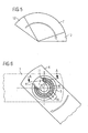
- Fig. 1 shows a section through an embodiment of the joint according to the invention in side view.
- the axis of rotation 1 lies in the plane of the drawing.
- a rivet pin 2 which pivotally connects the hinge parts 3, 4 together.
- the joint parts are for example kinematics link.
- the joint further comprises an angle sensor with a potentiometer 5, which is arranged fixed to the upper hinge part 4.
- the lower joint part 3 is pivotable relative to the potentiometer 5 and the upper joint part 4 about the pivot axis 1.
- the potentiometer 5 of the angle sensor comprises a resistance path 6, which extends in a circular arc around a recess 7 of the angle encoder.
- a coupling element in the form of a mechanical grinder 8 is fixedly attached to the lower joint part 3. In the first pivot angle position shown in FIG. 2, the wiper 8 cooperates with the resistance track 6 and via the electrical leads 10, a pivot angle-dependent resistance value can be measured and thus an angle signal can be detected.
- FIG. 8 shows a radial section through the potentiometer 5.
- the potentiometer comprises a resistance track 6 and a track 9.
- the track 9 is disposed on a flexible top of the potentiometer 5 and is spaced from the resistance track 6 when the slider 8 with the potentiometer 5 does not interact.
- FIG. 8 shows the interaction of the grinder 8 with the film potentiometer 5.
- the grinder 8 presses mechanically on the flexible upper side of the film potentiometer 5 and thus establishes an electrical contact between the conductor track 9 and the resistance path 6 within the interaction region, as shown. Therefore, an electrical resistance of the potentiometer 5 can be tapped off via the electrical supply lines 10, which depends on the location of the interaction between the wiper 8 and the film potentiometer 5 and thus depends on the pivoting angle of the joint parts 3, 4.
- FIG. 3 a of Fig. 2 different pivot angle of the joint is shown.
- the grinder 8 is in a second pivot angle position above the recess 7.
- the grinder 8 does not interact with the potentiometer 5 in this position. Therefore, the resistance of the potentiometer 5 in this swing angle range of the pivot angle of the two joint parts 3, 4 is independent. In other words, no angle signal is generated.
- the joint is shown in a third pivot angle position, in which the wiper 8 cooperates with the potentiometer 5, and an angle-dependent signal on the potentiometer 5 can be tapped.
- FIGS. 2 to 4 show the method sequence during the pivoting of the two joint parts 3, 4 relative to one another.
- the Articulated parts 3, 4 in a first pivoting angle position, in which the wiper 8 cooperates with the resistance path 6 of the film potentiometer 5 and a corresponding angle signal can be tapped on the potentiometer 5.
- the grinder 8 enters the recess 7, and the grinder 8 does not cooperate with the resistance path 6 of the potentiometer 5, which is why no pivot angle-dependent signal can be tapped on the potentiometer 5.
- Upon further pivoting of the joint parts 3, 4 of the wiper 8 passes completely over the recess 7 and reaches the opposite edge of the recess 7.
- the grinder 8 Upon further pivoting of the joint parts 3, 4, the grinder 8 again cooperates with the resistance element 6 of the potentiometer 5 and it can again an angle signal at the potentiometer 5 can be tapped.
- This method allows the end positions of the pivoting movement to have a large angular spacing, for example 360 ° or even more.
- the maximum angle of a pivoting movement is therefore not limited by the angular range over which the circular arc-shaped resistance element 6 of the potentiometer 5 extends.
- the measuring shadow 7 is shown schematically, which is formed by the recess 7.
- the wiper 8 cooperates with the potentiometer 5 and at the angle sensor, a pivot angle-dependent signal can be tapped.
- the coupling element is above the recess 7.
- inlet bevels 11 for the wiper 8 are shown on both sides of the recess 7.
- the grinder 8 is shown immediately above an inlet slope 11, that is, when entering or exiting from the recess 7.
- FIG. 7 shows a corresponding side view along the section line AA drawn in FIG. 6.
- the grinder 8 is arranged on the lower joint part 3 and the potentiometer 5 on the upper joint part 4. At the edge of the recess 7 of the angle encoder or the potentiometer 5 is chamfered, so that an inlet slope 11 is formed, which the input and Leaving the grinder 8 supported from or into the recess 7 and thereby designed wear.
Abstract
Description
Die vorliegende Erfindung bezieht sich auf einen Winkelgeber mit Montageöffnung zur Anbringung an einem Gelenk, insbesondere an einem Cabriodachgelenk.The present invention relates to an angle transmitter with mounting opening for attachment to a joint, in particular to a convertible roof joint.
Es ist bekannt, zurückklappbare Verdecke von Cabriolet-Fahrzeugen mit Antrieben auszustatten, welche ein vollständig automatisches Ein- und Ausklappen des Verdecks ermöglichen. Ein solches Cabriodach besteht in der Regel aus einer Mehrzahl von Elementen, welche über Gelenke miteinander verbunden sind. Zur Betätigung der einzelnen Dachelemente werden elektrische, hydraulische oder sonstige Antriebe verwendet. Dabei ist es in der Regel notwendig oder zumindest wünschenswert, die einzelnen Dachelemente bzw. die entsprechenden Gelenke unabhängig voneinander anzusteuern. Um eine effektive Steuerung des Einklapp- bzw. Ausklappvorganges des Cabriodaches zu gewährleisten, ist daher die Kenntnis über die momentane Position zumindest einiger dieser Dachelemente notwendig.It is known to equip convertible tops of convertible vehicles with drives, which allow a fully automatic folding and unfolding of the top. Such a convertible roof is usually made of a plurality of elements which are interconnected by joints. To operate the individual roof elements electrical, hydraulic or other drives are used. It is usually necessary or at least desirable to control the individual roof elements or the corresponding joints independently. In order to ensure effective control of the folding or Ausklappvorganges the convertible roof, therefore, the knowledge of the current position of at least some of these roof elements is necessary.
In herkömmlichen Cabiodächern werden zur Messung der Position der Dachelemente Endschalter eingesetzt.In conventional cabins, limit switches are used to measure the position of the roof elements.
Aus der Druckschrift
Alternativ zur Anbringung des Winkelgebers an der Außenseite des Cabriodachgelenkes kann der Winkelgeber auch axial zwischen den Gelenkteilen, das heißt in einem geschützten Bereich zwischen den Dachkinematiklenkern des Gelenkes angeordnet werden. Dazu muss jedoch der Montageprozess der Kinematiklenker des Cabriodaches umgestellt werden, um die zusätzliche Anbringung des Winkelgebers zu ermöglichen.As an alternative to mounting the angle sensor on the outside of the convertible roof joint, the angle sensor can also be axially between the joint parts, that is be arranged in a protected area between the roof kinematic links of the joint. For this purpose, however, the assembly process of the kinematic handlebars of the convertible roof must be changed to allow the additional attachment of the angle encoder.
Findet die Lackierung der Kinematiklenker des Cabriodaches erst nach deren Zusammenbau statt, so wird der bereits verbaute Winkelgeber ebenfalls von dem Lackierschritt erfasst. In diesem Fall muss der Winkelgeber daher zusätzlichen Anforderungen genügen, beispielsweise im Falle einer KTL-Lackierung (Kathodische Tauchlackierung) den dabei entstehenden hohen Temperaturen widerstehen.If the painting of the kinematic handlebars of the convertible roof takes place only after their assembly, then the already installed angle encoder is also detected by the painting step. In this case, therefore, the angle sensor must meet additional requirements, for example, in the case of a cathodic dip-paint coating (cathodic dip painting) withstand the resulting high temperatures.
Es ist daher Aufgabe der vorliegenden Erfindung, einen Winkelgeber zu schaffen, welcher an einem Gelenk auch nach dessen Zusammenbau, insbesondere in dem geschützten Bereich zwischen den Gelenkteilen des Gelenks, montierbar ist.It is therefore an object of the present invention to provide an angle sensor which can be mounted on a joint even after its assembly, in particular in the protected area between the joint parts of the joint.
Diese Aufgabe wird durch einen Winkelgeber, durch ein Gelenk, durch ein Verfahren sowie durch ein Cabriodachgelenk gemäß den unabhängigen Ansprüchen gelöst. Vorteilhafte Ausgestaltungen sind in den untergeordneten Ansprüchen angegeben.This object is achieved by an angle transmitter, by a joint, by a method and by a convertible roof joint according to the independent claims. Advantageous embodiments are specified in the subordinate claims.
Der Erfindung liegt die Erkenntnis zugrunde, dass beim Verschwenken der Gelenkteile eines Gelenkes in der Regel nur das Erreichen bzw. das Annähern an eine vorbestimmte Endlage genau ermittelt werden muss, da im Zwischenbereich der Antrieb der Gelenkteile beispielsweise mit voller Leistung arbeitet. Daher ist das Erfassen des relativen Schwenkwinkels der Gelenkteile zueinander nur in der Nähe dieser Endlagen notwendig.The invention is based on the finding that when pivoting the joint parts of a joint usually only the reaching or approaching to a predetermined end position must be accurately determined, since in the intermediate region of the drive of the joint parts, for example, operates at full capacity. Therefore, the detection of the relative pivot angle of the joint parts to each other only in the vicinity of these end positions is necessary.
Der erfindungsgemäße Winkelgeber zum Erfassen eines relativen Schwenkwinkels zwischen einem ersten und einem zweiten Gelenkteil, welche unter Ausbildung einer Schwenkachse schwenkbar miteinander verbunden sind, umfasst eine elektrische Schaltungskomponente mit mindestens einem elektrischen Widerstandselement, welches relativ zu dem ersten Gelenkteil ortsfest so anordenbar ist, dass es die Schwenkachse zumindest teilweise umgibt, und mit einem Koppelelement, welches relativ zu dem zweiten Gelenkteil ortsfest anordenbar ist, und im Zusammenwirken mit dem mindestens einem Widerstandselement einen Widerstandswert der elektrischen Schaltungskomponente beeinflusst. Der erfindungsgemäße Winkelgeber umfasst weiterhin eine Ausnehmung, in welche die Schwenkachse radial aufnehmbar ist, wobei der Winkelgeber so ausgebildet ist, dass das Koppelelement beim Verschwenken der Gelenkteile relativ zueinander zwischen einer ersten Position, in der das Koppelelement mit dem mindestens einen Widerstandselement zusammenwirkt, und einer zweiten Position, welche innerhalb der Ausnehmung liegt, verlagerbar ist.The angle encoder according to the invention for detecting a relative pivoting angle between a first and a second hinge part, which are pivotally connected together to form a pivot axis comprises an electrical circuit component having at least one electrical resistance element which is so arranged relative to the first hinge part stationary that it Swivel axis at least partially surrounds, and with a Coupling element which is stationary relative to the second joint part can be arranged, and in cooperation with the at least one resistive element influences a resistance value of the electrical circuit component. The angle encoder according to the invention further comprises a recess into which the pivot axis is radially receivable, wherein the angle sensor is formed so that the coupling element during pivoting of the joint parts relative to each other between a first position in which the coupling element cooperates with the at least one resistive element, and a second position, which lies within the recess, is displaceable.
Die erste Position fällt in einen ersten Schwenkwinkelbereich, in welchem das Koppelelement bei Blickrichtung entlang der Schwenkachse oberhalb des Widerstandselementes angeordnet ist und mit diesem zusammenwirkt. Beim Verschwenken der Gelenkteile innerhalb dieses ersten Schwenkwinkelbereiches verändert sich der Ort, an welchem das Koppelelement mit dem Widerstandselement zusammenwirkt, wodurch die elektrische Schaltungskomponente einen winkelabhängigen elektrischen Widerstandswert aufweist. Der Widerstandswert der elektrischen Schaltungskomponente kann durch eine geeignete äußere Beschaltung abgefragt werden, wodurch ein Winkelsignal gebildet wird. Die zweite Position fällt in einen zweiten Schwenkwinkelbereich, in welchem bei Blickrichtung entlang der Schwenkachse das Koppelelement oberhalb der Ausnehmung angeordnet ist. Beim Verschwenken der Gelenkteile innerhalb dieses zweiten Schwenkwinkelbereiches wirkt das Koppelelement mit dem Widerstandselement nicht zusammen, und der Widerstandswert der elektrischen Schaltungskomponente ist unabhängig von dem relativen Winkel zwischen dem ersten und dem zweiten Gelenkteil und beispielsweise konstant.The first position falls within a first pivoting angle range, in which the coupling element is arranged in the viewing direction along the pivot axis above the resistance element and cooperates therewith. During pivoting of the joint parts within this first pivoting angle range, the location at which the coupling element interacts with the resistance element changes, whereby the electrical circuit component has an angle-dependent electrical resistance value. The resistance value of the electrical circuit component can be interrogated by a suitable external circuit, whereby an angle signal is formed. The second position falls within a second pivot angle range, in which the coupling element is arranged above the recess when viewed along the pivot axis. During pivoting of the hinge parts within this second pivoting angle range, the coupling element does not interact with the resistance element, and the resistance value of the electrical circuit component is independent of the relative angle between the first and the second hinge part and, for example, constant.
Das Koppelelement ist beispielsweise als Schleifer ausgebildet, welcher relativ zum ersten Gelenkteil und damit relativ zum Widerstandselement beweglich ist und elektrisch, mechanisch oder in einer sonstigen Art und Weise mit dem Widerstandselement zusammenwirkt. Das Widerstandselement kann sich bis zum Rand der Ausnehmung erstrecken oder von diesem beabstandet sein, so dass im letzteren Fall ein weiterer Schwenkwinkelbereich entsteht, in welchem das Koppelelement weder mit dem Widerstandselement wechselwirkt, noch oberhalb der Ausnehmung angeordnet ist. Das Widerstandselement muss sich somit nicht über den gesamten Winkelbereich des Winkelgebers erstrecken, welcher nicht in die Ausnehmung fällt.The coupling element is designed, for example, as a grinder, which is movable relative to the first joint part and thus relative to the resistance element and interacts electrically, mechanically or in any other way with the resistance element. The resistance element may extend to the edge of the recess or be spaced therefrom, so that in the latter case, a further pivoting angle range is formed, in which the coupling element interacts neither with the resistance element, nor is arranged above the recess. The resistance element must therefore be do not extend over the entire angular range of the angle sensor, which does not fall into the recess.
Die Ausnehmung, in welche die Schwenkachse aufgenommen werden kann, reicht bis zu einem Rand des Winkelgebers, und gestattet somit die radiale Positionierung der Schwenkachse an einer vorbestimmten Position innerhalb des Winkelgebers. Das Vorsehen einer Ausnehmung gestattet das nachträgliche Anbringen des erfindungsgemäßen Winkelgebers durch einfaches Aufstecken auch beispielsweise im geschützten Bereich zwischen den Gelenkteilen eines bereits montierten Gelenks. Dadurch werden wesentliche Nachteile von bekannten geschlossenen Potentiometern überwunden, der erprobte Montageprozess von Gelenken muss nicht verändert werden und der Winkelgeber muss Umgebungsbedingungen widerstehen können, welche nur während des Montagesprozesses des Gelenkes auftreten. Der erfindungsgemäße Winkelgeber kann auch bei bereits vorhandenen Gelenken nachgerüstet werden.The recess, in which the pivot axis can be accommodated, extends to an edge of the angle sensor, and thus allows the radial positioning of the pivot axis at a predetermined position within the angle sensor. The provision of a recess allows the subsequent attachment of the angle sensor according to the invention by simply plugging in, for example, in the protected area between the joint parts of an already mounted joint. As a result, significant disadvantages of known closed potentiometers are overcome, the proven assembly process of joints need not be changed and the angle sensor must be able to withstand environmental conditions that occur only during the assembly process of the joint. The angle encoder according to the invention can also be retrofitted to existing joints.
Das Widerstandselement kann an dem ersten Gelenkteil direkt oder mit Hilfe eines oder mehrerer weiterer Konstruktionsteile befestigt werden. Ebenso kann das Koppelelement an dem zweiten Gelenkteil unmittelbar oder mit Hilfe eines oder mehrerer weiterer Konstruktionselemente befestigt werden. Dazu können das erste und das zweite Gelenkteil Vertiefungen oder sonstige Einrichtungen aufweisen, welche die Befestigung des Widerstandselementes bzw. des Koppelelements unterstützen.The resistance element can be attached to the first joint part directly or with the help of one or more other structural parts. Likewise, the coupling element can be attached to the second joint part directly or by means of one or more further construction elements. For this purpose, the first and the second hinge part can have depressions or other devices which support the attachment of the resistance element or of the coupling element.
Die elektrische Schaltungskomponente des Winkelgebers kann auf dem ersten und zweiten Gelenkteil derart angeordnet werden, dass die erste Position eine Endlage der Schwenkbewegung der Gelenkteile relativ zueinander darstellt. Dadurch kann das Erreichen der Endlage anhand des Widerstandswertes der elektrischen Schaltungskomponente erkannt werden.The electrical circuit component of the angle encoder can be arranged on the first and second joint part such that the first position represents an end position of the pivoting movement of the joint parts relative to each other. As a result, the reaching of the end position can be detected on the basis of the resistance value of the electrical circuit component.
In einer vorteilhaften Ausgestaltung des erfindungsgemäßen Winkelgebers ist das Koppelelement eingerichtet, beim Schwenken der Gelenkteile relativ zueinander, die Ausnehmung vollständig überstreichen zu können, um in einer dritten Position erneut mit dem mindestens einen Widerstandselement zusammenzuwirken.In an advantageous embodiment of the angle encoder according to the invention, the coupling element is set up, when pivoting the joint parts relative to each other, to sweep the recess completely to cooperate again in a third position with the at least one resistance element.
Die erste und die dritte Position definieren dabei beispielsweise die Endlagen einer Schwenkbewegung der Gelenkteile, an denen der Winkelgeber anbringbar ist. Beide Endlagen liegen somit in einem Schwenkwinkelbereich, in welchem eine Wechselwirkung des Koppelelementes mit dem Widerstandselement stattfindet und somit das Erreichen dieser Endlagen anhand des Widerstandswertes der elektrischen Schaltungskomponente festgestellt werden kann. Zwischen den beiden Endlagen überstreicht das Koppelelement die Ausnehmung vollständig, das heißt, das Koppelelement tritt im Laufe der Schwenkbewegung beispielsweise azimutal in die Ausnehmung ein und aus dieser beispielsweise auf der gegenüberliegenden Seite der Ausnehmung wieder aus, wodurch in einem Zwischenbereich der Schwenkbewegung das Koppelelement mit dem Widerstandselement nicht zusammenwirkt und demzufolge an dem Winkelgeber kein Schwenkwinkel-abhängiges Winkelsignal abgegriffen werden kann. Dies ist beispielsweise dann nicht notwendig, wenn der Schwenkwinkel in diesem Zwischenbereich nicht erfasst werden muss, weil die Schwenkbewegung z. B. mit maximaler Geschwindigkeit ablaufen bzw. der Antrieb der Gelenkteile auf maximale Leistung gehen soll. Auf beiden Seiten der Ausnehmung kann die Wechselwirkung des Koppelelementes mit demselben oder mit verschiedenen Widerstandselementen stattfinden.The first and the third position define, for example, the end positions of a pivoting movement of the joint parts, to which the angle encoder can be attached. Both end positions are thus in a swivel angle range in which an interaction of the coupling element takes place with the resistance element and thus the achievement of these end positions can be determined based on the resistance value of the electrical circuit component. Between the two end positions, the coupling element passes over the recess completely, that is, the coupling element occurs in the course of the pivoting movement, for example, azimuthally in the recess and out of this example on the opposite side of the recess again, whereby in an intermediate region of the pivoting movement of the coupling element with the Resistance element does not cooperate and therefore can not be tapped at the angle encoder pivot angle-dependent angle signal. This is not necessary, for example, if the pivot angle does not have to be detected in this intermediate region because the pivoting movement z. B. run at maximum speed or the drive of the joint parts should go to maximum power. On both sides of the recess, the interaction of the coupling element can take place with the same or with different resistance elements.
Die Auslegung des Winkelgebers derart, dass ein vollständiges Überstreichen der Ausnehmung vorgesehen ist, hat den Vorteil, dass die beiden Endlagen der Schwenkbewegung voneinander weit entfernt liegen können und deren Abstand nicht durch den Messschatten, welche die Ausnehmung definiert, begrenzt ist. Insbesondere können damit die Endlagen einer Schwenkbewegung um 360 Winkelgrad und mehr erfasst werden. Weiterhin ergeben sich durch die Möglichkeit mit dem Koppelelement die Ausnehmung überstreichen zu können zusätzliche Freiheitsgrade bei der Anbringung des Widerstandselements und des Koppelelements an den Gelenkteilen.The design of the angle sensor such that a complete sweeping the recess is provided, has the advantage that the two end positions of the pivoting movement can be far away from each other and whose distance is not limited by the measuring shadow, which defines the recess. In particular, so that the end positions of a pivoting movement can be detected by 360 degrees and more. Furthermore, the option of being able to cover the recess with the coupling element results in additional degrees of freedom in the attachment of the resistance element and the coupling element to the joint parts.
In einer weiteren vorteilhaften Ausgestaltung umfasst der Winkelgeber eine Einlaufschräge für das Koppelelement am Rand der Ausnehmung. Dadurch wird der räumliche Übertritt des Koppelelementes zwischen dem Bereich der Ausnehmung und dem Bereich, in welchem das Koppelelement mit dem mindestens einen Widerstandselement zusammenwirkt, unterstützt. Vorzugsweise umfasst der Winkelgeber zwei Einlaufschrägen zu beiden Seiten der Ausnehmung, um auch ein vollständiges Überstreichen der Ausnehmung und somit das Verfahren des Koppelelementes von der ersten in die dritte Position zu unterstützen.In a further advantageous embodiment of the angle encoder comprises an inlet slope for the coupling element at the edge of the recess. As a result, the spatial transfer of the coupling element between the region of the recess and the region in which the coupling element with the at least a resistive element cooperates supported. Preferably, the angle encoder comprises two inlet slopes on both sides of the recess in order to support a complete sweeping of the recess and thus the method of the coupling element from the first to the third position.
In einer weiteren vorteilhaften Ausgestaltung des Winkelgebers ist das Widerstandselement zumindest teilweise kreisbogenförmig ausgebildet, und die Ausnehmung des Winkelgebers ist derart ausgebildet, dass die Schwenkachse im Kreisbogenmittelpunkt des Widerstandselementes radial angeordnet werden kann. Bei Anbringung am Gelenkteil ist der Abstand des Koppelelements von der Schwenkachse vorzugsweise gleich dem Radius des kreisbogenförmigen Widerstandselements, wodurch das Koppelelement durch die Schwenkbewegung der Gelenkteile oberhalb des Widerstandselements verfahren werden kann.In a further advantageous embodiment of the angle sensor, the resistance element is at least partially circular arc-shaped, and the recess of the angle sensor is designed such that the pivot axis can be arranged radially in the circular arc center of the resistance element. When mounted on the hinge part, the distance of the coupling element from the pivot axis is preferably equal to the radius of the circular arc-shaped resistance element, whereby the coupling element can be moved by the pivotal movement of the hinge parts above the resistance element.
In einer weiteren vorteilhaften Ausgestaltung des Winkelgebers ist dessen elektrische Schaltungskomponente Teil eines Folienpotentiometer. Das Koppelelement ist dabei beispielsweise als mechanischer Schleifer ausgebildet. Unmittelbar oberhalb der Widerstandsbahn ist eine flexible Leitungsbahn angeordnet, welche der mechanische Schleifer in seinem Wechselwirkungsbereich auf die Widerstandsbahn niederdrückt, und somit einen elektrischen Kontakt zwischen Leitungsbahn und Widerstandsbahn herstellt. Eine solche Ausbildung der elektrischen Schaltungskomponente des Winkelgebers als Teil eines Folienpotentiometers gewährleistet eine geringe Aufbauhöhe des Winkelgebers. Dadurch verbraucht der Winkelgeber keinen oder nur wenig Bauraum und er kann vorzugsweise in dem geschützten Bereich zwischen den Gelenkteilen angeordnet werden. Um einen verschleißarmen Betrieb des Winkelgebers zu gewährleisten, kann der mechanische Schleifer ein Federelement und/oder eine rollende Kugel, welche auf der Leitungsbahn des Folienpotentiometers abrollt, umfassen.In a further advantageous embodiment of the angle sensor whose electrical circuit component is part of a film potentiometer. The coupling element is formed, for example, as a mechanical grinder. Immediately above the resistance path, a flexible path is arranged, which presses down the mechanical slider in its interaction region on the resistance path, and thus produces an electrical contact between the pathway and resistance path. Such a design of the electrical circuit component of the angle encoder as part of a Folienpotentiometers ensures a low overall height of the angle sensor. As a result, the angle encoder consumes little or no space and it can preferably be arranged in the protected area between the joint parts. In order to ensure a low-wear operation of the angle sensor, the mechanical grinder may include a spring element and / or a rolling ball, which rolls on the path of the film potentiometer.
Ein zweiter Aspekt der Erfindung betrifft ein Gelenk, welches ein erstes und ein zweites Gelenkteil unter Ausbildung einer Schwenkachse schwenkbar miteinander verbindet. Das Gelenk umfasst einen erfindungsgemäßen Winkelgeber, dessen Widerstandselement relativ zu dem ersten Gelenkteil und dessen Koppelelement relativ zum zweiten Gelenkteil ortsfest angeordnet ist. Die Schwenkachse des Gelenks ist innerhalb der radial offenen Ausnehmung des Winkelgebers angeordnet. Damit kann der Schwenkwinkel des Gelenks als Widerstandswert der elektrischen Schaltungskomponente erfasst werden, wenn das Koppelelement mit dem Widerstandselement des Winkelgebers zusammenwirkt.A second aspect of the invention relates to a joint which pivotally connects a first and a second joint part with the formation of a pivot axis. The joint comprises an angle sensor according to the invention, the resistance element of which is arranged relative to the first joint part and its coupling element relative to the second joint part stationary. The pivot axis of the joint is arranged within the radially open recess of the angle sensor. Thus, the pivot angle of the joint can be detected as a resistance value of the electrical circuit component when the coupling element cooperates with the resistance element of the angle sensor.
In einer vorteilhaften Ausgestaltung des Gelenks ist der Winkelgeber bezogen auf die Schwenkachse räumlich zwischen dem ersten und dem zweiten Gelenkteil angeordnet. Damit befindet sich der Winkelgeber in einem geschützten Bereich, was die Beschädigungsgefahr für den Winkelgeber reduziert.In an advantageous embodiment of the joint of the angle encoder is arranged relative to the pivot axis spatially between the first and the second hinge part. Thus, the angle encoder is located in a protected area, which reduces the risk of damage to the angle encoder.
Ein weiterer Aspekt der Erfindung betrifft eine Kinematikvorrichtung für ein Cabriodach, mit einem Cabriodachgelenk, welches als erfindungsgemäßes Gelenk aufgebaut ist, mit einem Antrieb zum Betätigen des Cabriodachgelenks und mit einer Kontrolleinrichtung zum Erfassen eines Winkelsignals an dem Winkelgeber und zum Ansteuern des Antriebs in Abhängigkeit von dem Winkelsignal. Der Antrieb kann elektrisch, hydraulisch oder in sonstiger Art und Weise aufgebaut sein. Die Kontrolleinrichtung steuert das Ein- und Ausfahren des Cabriodaches, erkennt das Erreichen von Endlagen, steuert und regelt den Bewegungsablauf der verschiedenen Dachelemente unabhängig voneinander und erkennt Fehlersituationen. Die Kontrolleinrichtung ist dabei ausgelegt, das Auftreten einer Messunterbrechung des Winkelsignals zuzulassen.Another aspect of the invention relates to a kinematic device for a convertible roof, with a convertible roof joint, which is constructed as a hinge according to the invention, with a drive for actuating the convertible roof link and with a control device for detecting an angle signal to the angle sensor and for driving the drive in response to the angle signal. The drive can be constructed electrically, hydraulically or in any other way. The control device controls the extension and retraction of the convertible roof, detects the reaching of end positions, controls and regulates the movement of the various roof elements independently and detects error situations. The control device is designed to allow the occurrence of a measurement interruption of the angle signal.
Ein weiterer Aspekt der Erfindung betrifft ein Verfahren zum Schwenken eines ersten und eines zweiten Gelenkteils relativ zueinander unter Verwendung eines erfindungsgemäßen Winkelgebers, dessen Widerstandselement relativ zu dem ersten Gelenkteil und dessen Koppelelement relativ zu dem zweiten Gelenkteil ortsfest angeordnet sind, wobei die Schwenkachse innerhalb der Ausnehmung des Winkelgebers angeordnet ist. Das Verfahren umfasst den Schritt des Verlagerns des Koppelelementes zwischen der ersten und der zweiten Position durch Schwenken der Gelenkteile relativ zueinander, wobei das Koppelelement an der ersten Position mit dem mindestens einen Widerstandselement des Winkelgebers zusammenwirkt und das Koppelelement an der zweiten Position oberhalb der Ausnehmung liegt.Another aspect of the invention relates to a method for pivoting a first and a second joint part relative to one another using an angle sensor according to the invention, the resistance element are arranged relative to the first joint part and its coupling element fixed relative to the second joint part, wherein the pivot axis within the recess of the Angle encoder is arranged. The method comprises the step of displacing the coupling element between the first and the second position by pivoting the hinge parts relative to each other, wherein the coupling element cooperates at the first position with the at least one resistance element of the angle encoder and the coupling element is located at the second position above the recess.
Eine vorteilhafte Ausgestaltung des erfindungsgemäßen Verfahrens umfasst den weiteren Schritt des Verlagerns eines Koppelelements zwischen der zweiten und der dritten Position durch Schwenken der Gelenkteile relativ zueinander, wobei das Koppelelement an der dritten Position erneut mit dem mindestens einen Widerstandselement zusammenwirkt. Beim Verlagern des Koppelelements von der ersten in die dritte Position überstreicht das Koppelelement die Ausnehmung des Winkelgebers vollständig.An advantageous embodiment of the method according to the invention comprises the further step of displacing a coupling element between the second and the third position by pivoting the hinge parts relative to each other, wherein the coupling element cooperates again at the third position with the at least one resistance element. When displacing the coupling element from the first to the third position, the coupling element completely covers the recess of the angle sensor.
Eine weitere vorteilhafte Ausgestaltung des erfindungsgemäßen Verfahrens umfasst den weiteren Schritt des Beenden des Schwenkens, wenn ein Winkelsignal des Winkelgebers das Erreichen einer Endlage anzeigt.A further advantageous embodiment of the method according to the invention comprises the further step of ending the pivoting, when an angle signal of the angle sensor indicates the reaching of an end position.
Gemäß einer weiteren vorteilhaften Ausgestaltung des erfindungsgemäßen Verfahrens wird vor dem Beenden des Schwenkens der folgende Schritt durchgeführt: Verlangsamen des Schwenkens, wenn das Winkelsignal das Erreichen einer vorbestimmten Position vor der Endlage anzeigt. Das Erreichen dieser vorbestimmten Position zeigt an, dass das Erreichen der Endlage bevorsteht. Das Verlangsamen des Schwenkens hat den Vorteil, dass die Endlage der Schwenkbewegung nicht mit voller Schwenkgeschwindigkeit erreicht wird, sondern mit reduzierter Schwenkgeschwindigkeit, was den Verschleiß der Bauteile herabsetzt und andererseits den Bedienungskomfort erhöht, da die Gelenkteile und daran möglicherweise angebrachte Bauteile in ihre vorgesehene Endlage sanft einfahren.According to a further advantageous embodiment of the method according to the invention, the following step is performed before the end of the pivoting: slowing down the pivoting when the angle signal indicates the reaching of a predetermined position before the end position. The reaching of this predetermined position indicates that the reaching of the end position is imminent. The slowing down of the pivoting has the advantage that the end position of the pivoting movement is not achieved with full pivoting speed, but with reduced pivoting speed, which reduces the wear of the components and on the other hand increases the ease of use, since the hinge parts and possibly attached components in their intended end position gently retract.
Ein weiterer Aspekt der Erfindung betrifft ein Cabriodachgelenk, welches ein erstes und ein zweites Gelenkteil unter Ausbildung einer Schwenkachse schwenkbar miteinander verbindet. Das Cabriodachgelenk umfasst einen Winkelgeber zum Erfassen eines relativen Schwenkwinkels zwischen dem ersten und dem zweiten Gelenkteil. Der Winkelgeber umfasst eine elektrische Schaltungskomponente mit mindestens einem Widerstandselement, welches relativ zu dem ersten Gelenkteil ortsfest so angeordnet ist, dass es die Schwenkachse zumindest teilweise umgibt und mit einem Koppelelement, welches relativ zu dem zweiten Gelenkteil ortsfest angeordnet ist und im Zusammenwirken mit dem mindestens einen Widerstandselement einen Widerstandswert der elektrischen Schaltungskomponente beeinflusst. Der Winkelgeber umfasst eine radial offene Ausnehmung, in welcher die Schwenkachse angeordnet ist. Der Winkelgeber kann wegen der radial offenen Ausnehmung nachträglich an einem bereits montierten Cabriodachgelenk montiert werden.Another aspect of the invention relates to a convertible roof hinge, which pivotally connects a first and a second hinge part with the formation of a pivot axis. The convertible roof hinge comprises an angle sensor for detecting a relative pivoting angle between the first and the second hinge part. The angle encoder comprises an electrical circuit component having at least one resistance element which is arranged fixed relative to the first joint part so that it at least partially surrounds the pivot axis and with a coupling element which is arranged stationary relative to the second joint part and in cooperation with the at least one Resistance element influences a resistance value of the electrical circuit component. The angle encoder comprises a radially open recess in which the pivot axis is arranged. The angle encoder can because of the radially open recess are subsequently mounted on an already mounted convertible roof joint.
In einer vorteilhaften Ausgestaltung des erfindungsgemäßen Cabriodachgelenks ist dessen elektrische Schaltungskomponente Teil eines Folienpotentiometers.In an advantageous embodiment of the invention Cabriodachgelenks whose electrical circuit component is part of a Folienpotentiometers.
Im Folgenden wird die Erfindung anhand eines Ausführungsbeispieles in Verbindung mit den Zeichnungsfiguren näher erläutert. Es zeigen:
- Figur 1 :
- eine Seitenansicht des erfindungsgemäßen Gelenks;
- Figuren 2-4:
- den Bewegungsablauf des erfindungsgemäßen Verfahrens in Draufsicht auf das Gelenk entlang der Schwenkachse;
- Figur 5:
- eine schematische Darstellung der Messunterbrechung;
- Figur 6:
- den Übertritt des Koppelelementes vom Messbereich in den Messschatten;
- Figur 7:
- die Einlaufschräge des erfindungsgemäßen Winkelgebers; und
- Figur 8:
- das Koppelelement in Wechselwirkung mit dem Folienpotentiometer.
- FIG. 1:
- a side view of the joint according to the invention;
- Figures 2-4:
- the movement of the method according to the invention in plan view of the joint along the pivot axis;
- FIG. 5:
- a schematic representation of the measurement interruption;
- FIG. 6:
- the passage of the coupling element from the measuring range in the measuring shadow;
- FIG. 7:
- the inlet slope of the angle encoder according to the invention; and
- FIG. 8:
- the coupling element in interaction with the film potentiometer.
Fig. 1 zeigt einen Schnitt durch ein Ausführungsbeispiel des erfindungsgemäßen Gelenks in Seitenansicht. Die Drehachse 1 liegt in der Zeichenebene. Auf der Drehachse befindet sich ein Nietbolzen 2, welcher die Gelenkteile 3, 4 schwenkbar miteinander verbindet. Die Gelenkteile sind beispielsweise Kinematiklenker. Das Gelenk umfasst weiterhin einen Winkelgeber mit einem Potentiometer 5, welches an den oberen Gelenkteil 4 ortsfest angeordnet ist. Das untere Gelenkteil 3 ist relativ zu dem Potentiometer 5 und dem oberen Gelenkteil 4 um die Schwenkachse 1 schwenkbar.Fig. 1 shows a section through an embodiment of the joint according to the invention in side view. The axis of rotation 1 lies in the plane of the drawing. On the axis of rotation is a
Fig. 2 zeigt eine Draufsicht auf das erfindungsgemäße Gelenk entlang der Schwenkachse 1. Das Potentiometer 5 des Winkelgebers umfasst eine Widerstandsbahn 6, welche sich kreisbogenförmig um eine Ausnehmung 7 des Winkelgebers erstreckt. Ein Koppelelement in Form eines mechanischen Schleifers 8 ist an dem unteren Gelenkteil 3 ortsfest angebracht. In der in Fig. 2 dargestellten ersten Schwenkwinkelposition wirkt der Schleifer 8 mit der Widerstandsbahn 6 zusammen und über die elektrischen Zuleitungen 10 kann ein Schwenkwinkel-abhängiger Widerstandswert gemessen und somit ein Winkelsignal erfasst werden.2 shows a plan view of the joint according to the invention along the pivot axis 1. The
Fig. 8 zeigt einen radialen Schnitt durch das Potentiometer 5. Das Potentiometer umfasst eine Widerstandsbahn 6 und eine Leiterbahn 9. Die Leiterbahn 9 ist auf einer flexiblen Oberseite des Potentiometers 5 angeordnet und ist von der Widerstandsbahn 6 beabstandet, wenn der Schleifer 8 mit dem Potentiometer 5 nicht zusammenwirkt. In Fig. 8 ist dagegen das Zusammenwirken des Schleifers 8 mit dem Folienpotentiometer 5 dargestellt. Der Schleifer 8 drückt mechanisch auf die flexible Oberseite des Folienpotentiometers 5 und stellt somit innerhalb des Wechselwirkungsbereichs, wie dargestellt, einen elektrischen Kontakt zwischen der Leiterbahn 9 und der Widerstandsbahn 6 her. Über die elektrischen Zuleitungen 10 kann daher ein elektrischer Widerstand des Potentiometers 5 abgegriffen werden, welcher vom Ort des Zusammenwirkens zwischen Schleifer 8 und Folienpotentiometer 5 abhängt und somit vom Schwenkwinkel der Gelenkteile 3, 4 abhängig ist.Fig. 8 shows a radial section through the
In Fig. 3 ist ein von Fig. 2 verschiedener Schwenkwinkel des Gelenkes dargestellt. Hierbei befindet sich der Schleifer 8 in einer zweiten Schwenkwinkelposition oberhalb der Ausnehmung 7. Der Schleifer 8 wirkt in dieser Position mit dem Potentiometer 5 nicht zusammen. Daher ist der Widerstandswert des Potentiometers 5 in diesem Schwenkwinkelbereich von dem Schwenkwinkel der beiden Gelenkteile 3, 4 unabhängig. Es wird mit anderen Worten, kein Winkelsignal erzeugt.In Fig. 3 a of Fig. 2 different pivot angle of the joint is shown. Here, the
In Fig. 4 ist das Gelenk in einer dritten Schwenkwinkelposition dargestellt, in welcher der Schleifer 8 mit dem Potentiometer 5 zusammenwirkt, und ein winkelabhängiges Signal am Potentiometer 5 abgegriffen werden kann.4, the joint is shown in a third pivot angle position, in which the
Die Figuren 2 bis 4 zeigen den Verfahrensablauf beim Verschwenken der beiden Gelenkteile 3, 4 relativ zueinander. Zu Beginn des Verfahrens befinden sich die Gelenkteile 3, 4 in einer ersten Schwenkwinkelposition, in welcher der Schleifer 8 mit der Widerstandsbahn 6 des Folienpotentiometers 5 zusammenwirkt und ein entsprechendes Winkelsignal am Potentiometer 5 abgegriffen werden kann. Bei einem weiteren Verschwenken der Gelenkteile 3, 4 tritt der Schleifer 8 in die Ausnehmung 7 ein, und der Schleifers 8 wirkt mit der Widerstandsbahn 6 des Potentiometers 5 nicht zusammen, weswegen kein Schwenkwinkel-abhängiges Signal am Potentiometer 5 abgegriffen werden kann. Beim weiteren Verschwenken der Gelenkteile 3, 4 überstreicht der Schleifer 8 die Ausnehmung 7 vollständig und erreicht den gegenüberliegenden Rand der Ausnehmung 7. Beim weiteren Verschwenken der Gelenkteile 3, 4 wirkt der Schleifer 8 wieder mit dem Widerstandselement 6 des Potentiometers 5 zusammen und es kann wieder ein Winkelsignal am Potentiometer 5 abgegriffen werden. Dieses Verfahren gestattet, dass die Endlagen der Schwenkbewegung einen großen Winkelabstand, beispielsweise 360° oder auch darüber, aufweisen. Der maximale Winkel einer Schwenkbewegung ist daher nicht durch den Winkelbereich begrenzt, über welchen sich das kreisbogenförmige Widerstandselement 6 des Potentiometers 5 erstreckt.FIGS. 2 to 4 show the method sequence during the pivoting of the two
In Fig. 5 ist der Messschatten 7 schematisch dargestellt, welcher durch die Ausnehmung 7 entsteht. In den Randbereichen 12 des Messschattens 7 wirkt der Schleifer 8 mit dem Potentiometer 5 zusammen und an dem Winkelgeber kann ein Schwenkwinkel-abhängiges Signal abgegriffen werden. Im Messschatten 7 befindet sich das Koppelelement oberhalb der Ausnehmung 7. Beim Verschwenken der Gelenkteile 3, 4 relativ zueinander findet im Bereich des Messschattens 7 eine Messunterbrechung statt, in welcher kein Schwenkwinkel-abhängiges Signal abgegriffen werden kann.In Fig. 5 the measuring shadow 7 is shown schematically, which is formed by the recess 7. In the
In den Fig. 2, 3, 4 und 6 sind Einlaufschrägen 11 für den Schleifer 8 zu beiden Seiten der Ausnehmung 7 dargestellt. In Fig. 6 ist der Schleifer 8 unmittelbar oberhalb einer Einlaufschräge 11, das heißt beim Eintritt in bzw. beim Austritt aus der Ausnehmung 7 dargestellt. Fig. 7 zeigt eine entsprechende Seitenansicht entlang der in Fig. 6 eingezeichneten Schnittlinie A-A. Der Schleifer 8 ist auf dem unteren Gelenkteil 3 und das Potentiometer 5 auf dem oberen Gelenkteil 4 angeordnet. Am Rand der Ausnehmung 7 ist der Winkelgeber bzw. das Potentiometer 5 abgeschrägt, so dass eine Einlaufschräge 11 entsteht, welche das Ein- und Austreten des Schleifers 8 aus der bzw. in die Ausnehmung 7 unterstützt und dadurch verschleißarm gestaltet.In FIGS. 2, 3, 4 and 6, inlet bevels 11 for the
Claims (14)
gekennzeichnet durch
eine Ausnehmung (7), in welche die Schwenkachse (1) radial aufnehmbar ist, wobei der Winkelgeber so ausgebildet ist, dass das Koppelelement (8) beim Verschwenken der Gelenkteile (3, 4) relativ zueinander zwischen einer ersten Position, in der das Koppelelement (8) mit dem mindestens einen Widerstandselement (6) zusammenwirkt, und einer zweiten, innerhalb der Ausnehmung (7) liegenden Position verlagerbar ist.An angle sensor for detecting a relative pivoting angle between a first (4) and a second (3) pivotally connected to one another by forming a pivot axis (1), comprising an electrical circuit component with at least one resistance element (6) which is movable relative to the first joint part (3). 4) is stationary so that it at least partially surrounds the pivot axis (1), and a coupling element (8) which is stationary relative to the second joint part (3) and in conjunction with the at least one resistance element (6) has a resistance value the electrical circuit component is affected,
marked by
a recess (7), in which the pivot axis (1) is radially receivable, wherein the angle encoder is formed so that the coupling element (8) during pivoting of the joint parts (3, 4) relative to each other between a first position in which the coupling element (8) cooperates with the at least one resistance element (6), and a second, within the recess (7) lying position is displaced.
dadurch gekennzeichnet, dass das Koppelelement (8) eingerichtet ist, bei einem Schwenken der Gelenkteile (3, 4) relativ zueinander, die Ausnehmung (7) vollständig überstreichen zu können, um in einer dritten Position erneut mit dem mindestens einen Widerstandselement (6) zusammenzuwirken.An angle sensor according to claim 1,
characterized in that the coupling element (8) is arranged, upon pivoting of the joint parts (3, 4) relative to each other to be able to sweep the recess (7) completely in order to cooperate again in a third position with the at least one resistance element (6) ,
gekennzeichnet durch eine Einlaufschräge (11) für das Koppelelement (8) an mindestens einem Rand der Ausnehmung (7).An angle sensor according to claim 1 or claim 2,
characterized by an inlet bevel (11) for the coupling element (8) on at least one edge of the recess (7).
dadurch gekennzeichnet, dass das Widerstandselement (6) kreisbogenförmig ausgebildet ist und die Schwenkachse (1) im Kreisbogenmittelpunkt anordenbar ist.Angle transmitter according to one of the preceding claims,
characterized in that the resistance element (6) is formed in a circular arc and the pivot axis (1) can be arranged in the circular arc center.
dadurch gekennzeichnet, dass die elektrische Schaltungskompontente Teil eines Folienpotentiometers (5) istAngle transmitter according to one of the preceding claims,
characterized in that the electrical circuit component is part of a film potentiometer (5)
gekennzeichnet durch einen Winkelgeber nach einem der Ansprüche 1 bis 5, dessen Widerstandselement (6) relativ zu dem ersten Gelenkteil (4) und dessen Koppelelement (8) relativ zu dem zweiten Gelenkteil (3) ortsfest angeordnet sind, wobei die Schwenkachse (1) innerhalb der Ausnehmung (7) des Winkelgebers angeordnet ist.Joint which pivotally connects a first (4) and a second (3) joint part to form a pivot axis (1),
characterized by an angle encoder according to one of claims 1 to 5, whose resistance element (6) relative to the first hinge part (4) and its coupling element (8) relative to the second hinge part (3) are arranged stationary, wherein the pivot axis (1) within the recess (7) of the angle sensor is arranged.
dadurch gekennzeichnet, dass der Winkelgeber räumlich zwischen dem ersten und zweiten Gelenkteil (3, 4) angeordnet ist.Joint according to claim 6,
characterized in that the angle encoder is arranged spatially between the first and second hinge part (3, 4).
gekennzeichnet durch den weiteren Schritt:
characterized by the further step:
gekennzeichnet durch den weiteren Schritt:
characterized by the further step:
dadurch gekennzeichnet, dass vor Schritt c) der weitere Schritt durchgeführt wird:
characterized in that before step c) the further step is carried out:
dadurch gekennzeichnet, dass die Schwenkachse (1) innerhalb einer radial offenen Ausnehmung (7) des Winkelgebers angeordnet ist.Convertible roof hinge pivotally interconnecting a first and a second hinge part (3, 4) to form a pivot axis (1), comprising an angle sensor for detecting a relative pivot angle between the first and second hinge parts (3, 4) having an electrical circuit component at least one resistance element (6), which is arranged fixed relative to the first joint part (4) so that it at least partially surrounds the pivot axis (1), and a coupling element (8) which is arranged stationary relative to the second joint part (3) is and in cooperation with the at least one resistance element (6) influences the resistance value of the electrical circuit component comprises,
characterized in that the pivot axis (1) within a radially open recess (7) of the angle sensor is arranged.
dadurch gekennzeichnet, dass die elektrische Schaltungskomponente Teil eines Folienpotentiometer (5) ist.Convertible roof joint according to claim 13,
characterized in that the electrical circuit component is part of a film potentiometer (5).
Applications Claiming Priority (1)
| Application Number | Priority Date | Filing Date | Title |
|---|---|---|---|
| DE102006036102.4A DE102006036102B4 (en) | 2006-08-02 | 2006-08-02 | Angle encoder with mounting opening |
Publications (2)
| Publication Number | Publication Date |
|---|---|
| EP1886858A2 true EP1886858A2 (en) | 2008-02-13 |
| EP1886858A3 EP1886858A3 (en) | 2009-08-26 |
Family
ID=38511419
Family Applications (1)
| Application Number | Title | Priority Date | Filing Date |
|---|---|---|---|
| EP07014343A Withdrawn EP1886858A3 (en) | 2006-08-02 | 2007-07-20 | Angle transmitter with mounting aperture |
Country Status (2)
| Country | Link |
|---|---|
| EP (1) | EP1886858A3 (en) |
| DE (1) | DE102006036102B4 (en) |
Cited By (1)
| Publication number | Priority date | Publication date | Assignee | Title |
|---|---|---|---|---|
| GB2476378B (en) * | 2009-12-19 | 2015-09-23 | Gm Global Tech Operations Inc | A position sensor and use of the position sensor |
Families Citing this family (1)
| Publication number | Priority date | Publication date | Assignee | Title |
|---|---|---|---|---|
| DE102009059150A1 (en) * | 2009-12-19 | 2011-06-22 | GM Global Technology Operations LLC, ( n. d. Ges. d. Staates Delaware ), Mich. | Position transmitter and use of the position encoder |
Citations (3)
| Publication number | Priority date | Publication date | Assignee | Title |
|---|---|---|---|---|
| US5225747A (en) * | 1992-01-06 | 1993-07-06 | Asc Incorporated | Single-button actuated self-correcting automatic convertible top |
| US5525955A (en) * | 1992-11-10 | 1996-06-11 | Copal Company Limited | Capacitor coupled potentiometer |
| DE20016498U1 (en) * | 2000-09-23 | 2001-08-02 | Karmann Gmbh W | Device for detecting an angular position |
Family Cites Families (3)
| Publication number | Priority date | Publication date | Assignee | Title |
|---|---|---|---|---|
| CA2026873C (en) * | 1989-10-04 | 1997-06-17 | Stephen C. Jacobsen | Mechanical/electrical displacement transducer |
| DE19635159A1 (en) * | 1996-08-30 | 1998-03-05 | Zahnradfabrik Friedrichshafen | Angle of rotation sensor |
| DE102006006673A1 (en) * | 2006-02-14 | 2007-08-23 | Wilhelm Karmann Gmbh | Turning angle detector |
-
2006
- 2006-08-02 DE DE102006036102.4A patent/DE102006036102B4/en not_active Expired - Fee Related
-
2007
- 2007-07-20 EP EP07014343A patent/EP1886858A3/en not_active Withdrawn
Patent Citations (3)
| Publication number | Priority date | Publication date | Assignee | Title |
|---|---|---|---|---|
| US5225747A (en) * | 1992-01-06 | 1993-07-06 | Asc Incorporated | Single-button actuated self-correcting automatic convertible top |
| US5525955A (en) * | 1992-11-10 | 1996-06-11 | Copal Company Limited | Capacitor coupled potentiometer |
| DE20016498U1 (en) * | 2000-09-23 | 2001-08-02 | Karmann Gmbh W | Device for detecting an angular position |
Cited By (1)
| Publication number | Priority date | Publication date | Assignee | Title |
|---|---|---|---|---|
| GB2476378B (en) * | 2009-12-19 | 2015-09-23 | Gm Global Tech Operations Inc | A position sensor and use of the position sensor |
Also Published As
| Publication number | Publication date |
|---|---|
| DE102006036102B4 (en) | 2017-08-10 |
| DE102006036102A1 (en) | 2008-02-07 |
| EP1886858A3 (en) | 2009-08-26 |
Similar Documents
| Publication | Publication Date | Title |
|---|---|---|
| DE102008032075B4 (en) | Mounting mechanism for a position detection sensor | |
| EP2186405A1 (en) | Spray bar and method for controlling it | |
| EP3768579B1 (en) | System and method for pivoting a coupling component | |
| EP2871149A1 (en) | Drive for a slide of a locking system of a telescopic system of a crane arm | |
| EP2037027B1 (en) | Thread guide for flat knitting machines | |
| DE10023196A1 (en) | Device for detecting the angle of rotation between two components | |
| DE102006036102B4 (en) | Angle encoder with mounting opening | |
| EP1531290B1 (en) | Gear selector device | |
| DE2815888C2 (en) | Pressure dependent switch | |
| EP2861877A1 (en) | Ball-and-socket joint as engagement point for a driving element of a locking system | |
| DE3837981C2 (en) | Trucks or semitrailers with a forced steering additional axle | |
| EP2672041A2 (en) | Guide rail assembly | |
| EP3348764B1 (en) | Device for at least partially automatic actuation of a door wing | |
| DE10223449B4 (en) | Telescopic system with telescopic telescopic device | |
| EP1466862B1 (en) | Levelling device and levelling method for a workbasket of an elevating work platform | |
| WO2022069177A1 (en) | Locking device and locking method for a switch point drive and switch point drive | |
| EP2584097B1 (en) | Construction device | |
| EP2401903A1 (en) | Switching device for an agricultural distribution machine for dispensing seeds and/or fertilizers | |
| DE3041826C2 (en) | ||
| EP1873039B1 (en) | Method for adjusting the steering range of the electrical steering for an industrial truck | |
| DE69908093T2 (en) | RESISTANCE WELDING PLIERS WITH A MECHANICAL DIVIDING AND RESETTING DEVICE | |
| DE3234818C2 (en) | ||
| EP2037302B1 (en) | Device for limiting the turning angle of a rotatable object and optical observation device | |
| DE102006022330B4 (en) | Contacting arrangement with a printed circuit board and an attachable module for electrical contacting of the printed circuit board | |
| EP3248928A1 (en) | Z-shaped foldable crane |
Legal Events
| Date | Code | Title | Description |
|---|---|---|---|
| PUAI | Public reference made under article 153(3) epc to a published international application that has entered the european phase |
Free format text: ORIGINAL CODE: 0009012 |
|
| AK | Designated contracting states |
Kind code of ref document: A2 Designated state(s): AT BE BG CH CY CZ DE DK EE ES FI FR GB GR HU IE IS IT LI LT LU LV MC MT NL PL PT RO SE SI SK TR |
|
| AX | Request for extension of the european patent |
Extension state: AL BA HR MK YU |
|
| PUAL | Search report despatched |
Free format text: ORIGINAL CODE: 0009013 |
|
| AK | Designated contracting states |
Kind code of ref document: A3 Designated state(s): AT BE BG CH CY CZ DE DK EE ES FI FR GB GR HU IE IS IT LI LT LU LV MC MT NL PL PT RO SE SI SK TR |
|
| AX | Request for extension of the european patent |
Extension state: AL BA HR MK RS |
|
| RIC1 | Information provided on ipc code assigned before grant |
Ipc: G01B 7/30 20060101ALI20090721BHEP Ipc: G01D 5/165 20060101ALI20090721BHEP Ipc: B60R 16/037 20060101ALI20090721BHEP Ipc: B60J 7/12 20060101AFI20071011BHEP |
|
| AKX | Designation fees paid | ||
| STAA | Information on the status of an ep patent application or granted ep patent |
Free format text: STATUS: THE APPLICATION IS DEEMED TO BE WITHDRAWN |
|
| 18D | Application deemed to be withdrawn |
Effective date: 20100202 |
|
| REG | Reference to a national code |
Ref country code: DE Ref legal event code: 8566 |