EP1884854A2 - Device for heating premises - Google Patents
Device for heating premises Download PDFInfo
- Publication number
- EP1884854A2 EP1884854A2 EP07290937A EP07290937A EP1884854A2 EP 1884854 A2 EP1884854 A2 EP 1884854A2 EP 07290937 A EP07290937 A EP 07290937A EP 07290937 A EP07290937 A EP 07290937A EP 1884854 A2 EP1884854 A2 EP 1884854A2
- Authority
- EP
- European Patent Office
- Prior art keywords
- sensor
- detector
- mode
- heating
- comfort
- Prior art date
- Legal status (The legal status is an assumption and is not a legal conclusion. Google has not performed a legal analysis and makes no representation as to the accuracy of the status listed.)
- Granted
Links
- 238000010438 heat treatment Methods 0.000 title claims description 28
- 238000001514 detection method Methods 0.000 claims abstract description 26
- 230000033001 locomotion Effects 0.000 claims abstract description 16
- 238000005485 electric heating Methods 0.000 claims abstract description 9
- CURLTUGMZLYLDI-UHFFFAOYSA-N Carbon dioxide Chemical compound O=C=O CURLTUGMZLYLDI-UHFFFAOYSA-N 0.000 claims description 6
- 238000005516 engineering process Methods 0.000 claims description 6
- 230000008859 change Effects 0.000 claims description 4
- 229910002092 carbon dioxide Inorganic materials 0.000 claims description 3
- 239000001569 carbon dioxide Substances 0.000 claims description 3
- 230000009977 dual effect Effects 0.000 claims description 2
- 239000011159 matrix material Substances 0.000 claims description 2
- 238000002604 ultrasonography Methods 0.000 claims description 2
- 230000003321 amplification Effects 0.000 abstract description 2
- 238000003199 nucleic acid amplification method Methods 0.000 abstract description 2
- 238000007493 shaping process Methods 0.000 abstract description 2
- 239000011888 foil Substances 0.000 abstract 1
- 238000010586 diagram Methods 0.000 description 5
- 230000005855 radiation Effects 0.000 description 4
- 230000000750 progressive effect Effects 0.000 description 3
- 230000007704 transition Effects 0.000 description 3
- 238000012544 monitoring process Methods 0.000 description 2
- 238000001228 spectrum Methods 0.000 description 2
- 230000004913 activation Effects 0.000 description 1
- 230000001427 coherent effect Effects 0.000 description 1
- 230000000694 effects Effects 0.000 description 1
- 230000004048 modification Effects 0.000 description 1
- 238000012986 modification Methods 0.000 description 1
- 230000001105 regulatory effect Effects 0.000 description 1
- 230000035945 sensitivity Effects 0.000 description 1
- 230000009466 transformation Effects 0.000 description 1
Images

Classifications
-
- G—PHYSICS
- G05—CONTROLLING; REGULATING
- G05D—SYSTEMS FOR CONTROLLING OR REGULATING NON-ELECTRIC VARIABLES
- G05D23/00—Control of temperature
- G05D23/19—Control of temperature characterised by the use of electric means
- G05D23/1919—Control of temperature characterised by the use of electric means characterised by the type of controller
Abstract
Description
L'invention est relative à un dispositif de chauffage de locaux, en particulier au moyen d'appareils de chauffage électrique.The invention relates to a space heating device, in particular by means of electric heating apparatus.
On connaît de nombreux dispositifs programmables de régulation de température destinés à économiser l'énergie électrique dans les locaux inoccupés.Numerous programmable temperature control devices are known for saving electrical energy in unoccupied premises.
Ces dispositifs exigent cependant une programmation préalable du dispositif de régulation par l'utilisateur. Le changement fréquent de locaux, et le mode « nomade » d'occupation des locaux qui en résulte, contraignent l'utilisateur à changer fréquemment la programmation du dispositif de régulation, en fonction de circonstances imprévues ou de changements d'occupation.These devices, however, require prior programming of the control device by the user. The frequent change of premises, and the resulting "nomadic" mode of occupancy of premises, force the user to frequently change the programming of the control device, according to unforeseen circumstances or changes in occupancy.
Un inconvénient du dispositif de programmation connu résulte de ce qu'il nécessite une mise à jour et un suivi régulier de la programmation, pour lesquels l'utilisateur n'a pas toujours le temps nécessaire.A disadvantage of the known programming device results from the fact that it requires updating and regular monitoring of the programming, for which the user does not always have the necessary time.
L'absence de suivi et de mise à jour de la régulation entraîne ainsi des situations d'inconfort, des dépenses importantes d'énergie et des coûts économiques indésirables.The lack of monitoring and updating of the regulation thus leads to discomfort situations, significant energy expenditure and undesirable economic costs.
Un premier but de l'invention est de proposer un nouveau dispositif de chauffage de locaux tenant compte de la présence effective de personnes à l'intérieur des locaux, pour adapter en conséquence le mode de chauffage électrique correspondant.A first object of the invention is to provide a new space heating device taking into account the actual presence of people inside the premises, to adapt accordingly the corresponding electric heating mode.
Le document
Le détecteur de présence envisagé dans le document
Un deuxième but de l'invention est de proposer un nouveau dispositif de chauffage électrique, dans lequel la présence effective de personnes dans un local est détectée de manière améliorée, pour éviter la mise en oeuvre d'un mode de régulation inadapté.A second object of the invention is to propose a new electric heating device, in which the actual presence of people in a room is detected in an improved manner, to avoid the implementation of an unsuitable regulation mode.
L'invention a pour objet un dispositif de chauffage de locaux tenant compte de la présence effective de personnes à l'intérieur des locaux pour adapter le mode de chauffage électrique, caractérisé par le fait que le dispositif comporte au moins deux capteurs ou détecteurs de paramètres physiques, en vue de détecter, par coordination des signaux des au moins deux détecteurs ou capteurs de paramètres physiques, la présence effective d'une personne à l'intérieur d'un local à chauffer, pour adapter le mode de chauffage électrique, par exemple au mode de confort ou au mode économiqueThe subject of the invention is a space heating device that takes into account the effective presence of persons inside the premises to adapt the electric heating mode, characterized in that the device comprises at least two sensors or parameter detectors. in order to detect, by coordination of the signals of the at least two detectors or sensors of physical parameters, the effective presence of a person inside a room to be heated, to adapt the electric heating mode, for example comfort mode or economy mode
Selon d'autres caractéristiques alternatives de l'invention :
- les capteurs ou détecteurs de paramètres physiques peuvent être choisis dans l'ensemble comportant : un capteur ou détecteur de luminosité, un capteur ou détecteur de variation de mouvements, un capteur ou détecteur de présence absolue à balayage laser ; un capteur ou détecteur de présence absolue à matrice infrarouge, un capteur à hyperfréquence qui permet de déceler le déplacement d'un objet dans sa zone de surveillance, un capteur ou détecteur à ultrasons, un capteur ou détecteur périvolumétrique qui détecte le changement de pression, un capteur ou détecteur biovolumètrique ou double technologie qui associe les deux technologies: infrarouge et hyperfréquence ou infrarouge et ultrasons, un capteur ou détecteur de bruits, un capteur ou détecteur de variation de gaz carbonique, un capteur ou détecteur de champ radio fréquence.
- les signaux en provenance des capteurs ou détecteurs sont traités et injectés dans une unité de traitement numérique, par exemple un microcontrôleur.
- le dispositif comporte un moyen de réglage de seuil de luminosité, en vue de permettre une comparaison dudit seuil de luminosité à un signal de luminosité fourni par un capteur.
- le dispositif détermine un temps de base de fonctionnement des moyens de chauffage.
- le dispositif est un dispositif programmable en fonction de la valeur de la luminosité et en fonction de la valeur d'un paramètre représentatif choisi par comparaison de plusieurs signaux de paramètres physiques.
- le dispositif fonctionne selon une logique séparée en deux : une logique de détection et une logique de chauffage
- le dispositif comporte une unité de traitement numérique avec deux sorties, dont l'une alimente un moyen indicateur de fonctionnement du mode économique, et dont l'autre est reliée à un moyen indicateur de fonctionnement du mode de confort.
- le dispositif comporte une unité de traitement numérique dont une sortie est reliée à un moyen indicateur d'un objectif de température à atteindre dans le local à chauffer.
- the sensors or physical parameter detectors may be chosen from the assembly comprising: a brightness sensor or detector, a motion variation sensor or detector, an absolute scanning presence sensor or detector; an infrared matrix absolute presence sensor or detector, a microwave sensor which makes it possible to detect the movement of an object in its surveillance zone, an ultrasonic sensor or detector, a perivolumetric sensor or detector which detects the change in pressure, a biovolumetric or dual technology sensor or detector that combines the two technologies: infrared and microwave or infrared and ultrasound, a sensor or noise detector, a sensor or detector for variation of carbon dioxide, a sensor or radio frequency field detector.
- the signals coming from the sensors or detectors are processed and injected into a digital processing unit, for example a microcontroller.
- the device comprises a brightness threshold adjustment means, in order to allow a comparison of said brightness threshold with a brightness signal provided by a sensor.
- the device determines a basic operating time of the heating means.
- the device is a programmable device according to the value of the brightness and according to the value of a representative parameter chosen by comparing several physical parameter signals.
- the device operates in a separate logic in two: detection logic and heating logic
- the device comprises a digital processing unit with two outputs, one of which supplies an indicator means for operating the economic mode, and the other of which is connected to an indicator means for operating the comfort mode.
- the device comprises a digital processing unit whose output is connected to a means indicating a target temperature to be reached in the room to be heated.
L'invention sera mieux comprise grâce à la description qui va suivre donnée à titre d'exemple non limitatif en référence aux dessins annexés dans lesquels :
- la figure 1 représente schématiquement un organigramme de fonctionnement de dispositif selon l'invention.
- la figure 2 représente schématiquement un diagramme fonctionnel d'un dispositif de chauffage selon l'invention.
- la figure 3 représente schématiquement un exemple de circuit électronique pour la réalisation d'un dispositif selon l'invention.
- FIG. 1 schematically represents a device operating flow diagram according to the invention.
- FIG. 2 diagrammatically represents a functional diagram of a heating device according to the invention.
- FIG. 3 schematically represents an example of an electronic circuit for producing a device according to the invention.
En référence à la figure 1, un organigramme de fonctionnement de dispositif selon l'invention débute par une étape 100 de détection de luminosité à l'intérieur du local.Referring to Figure 1, a device operation flow chart according to the invention starts with a
A l'étape 101, la luminosité captée à l'étape 100 est comparée à un seuil prédéterminé. Si cette luminosité est inférieure au seuil prédéterminé, l'appareil de chauffage électrique est régulé à l'étape 400 en mode de chauffage économique.In
Si cette luminosité est supérieure au seuil prédéterminé, l'algorithme se poursuit à l'étape 200. La logique d'hystérésis connue en soi est mise en oeuvre pour éviter les basculements intempestifs autour du seuil.If this brightness is greater than the predetermined threshold, the algorithm continues in
A l'étape 102, une détection de la variation de mouvement à l'intérieur du local est effectuée. Si aucun mouvement n'est détecté à l'intérieur du local, la régulation est orientée à l'étape 112 vers le mode de fonctionnement économique de l'étape 400. Si un mouvement est détecté à l'intérieur du local, l'algorithme se poursuit.In
A l'étape 103, une détection de bruit dans le local est effectuée. Si aucun bruit n'est détecté dans le local, la régulation est orientée à l'étape 113 vers le mode de fonctionnement économique de l'étape 400. A l'étape 120, une vérification des niveaux de mouvement et de bruit est effectuée pour choisir le signal le plus distinct ou le plus cohérent, en vue de poursuivre l'algorithme à l'étape 200.In
Bien entendu, on peut, sans sortir du cadre de l'invention, prévoir des étapes de détection d'autres paramètres physiques différents : par exemple, il est possible de détecter à une étape 104 la variation du taux de gaz carbonique dans l'atmosphère, ou à une étape 105 la détection de la variation du champ radio fréquence à l'intérieur du local. Les signaux de détection peuvent ensuite être traités de manière analogue sans sortir du cadre de la présente invention.Of course, it is possible, without departing from the scope of the invention, to provide detection steps for other different physical parameters: for example, it is possible to detect at a
A l'étape 200, le signal représentatif choisi à l'étape 120 et le signal de luminosité comparé à l'étape 101 sont coordonnés, et leur simultanéité est vérifiée.In
Si les deux signaux indiquent simultanément à l'étape 200 une présence dans le local, la régulation est orientée vers l'étape 300 de fonctionnement en mode de confort.If both signals simultaneously indicate in step 200 a presence in the room, the control is directed to
Si les deux signaux représentatifs de la luminosité et du paramètre physique choisi comme représentatifs à l'étape 120 n'indiquent pas simultanément une présence, la régulation est orientée à l'étape 200 vers le mode de fonctionnement économique de l'étape 400.If the two signals representative of the brightness and the physical parameter chosen as representative in
Il est bien entendu possible de prévoir une temporisation, ou d'intercaler des filtres temporels ou fréquentiels entre les diverses étapes de fonctionnement.It is of course possible to provide a time delay, or to insert time or frequency filters between the various operating steps.
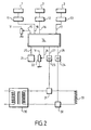
En référence à la figure 2, un diagramme fonctionnel de dispositif selon l'invention est représenté.With reference to FIG. 2, a device functional diagram according to the invention is shown.
Le dispositif comporte un moyen 1 de détection de luminosité, par exemple une photo diode qui dispose d'un propre microcontrôleur 11, un moyen 2 de détection de mouvement, par exemple une photopile apte à détecter les variations de rayonnement infrarouge, et un moyen 3 de détection de bruit, par exemple un microphone à électret.The device comprises a brightness detection means 1, for example a photo diode which has its own microcontroller 11, a motion detection means 2, for example a photocell capable of detecting the variations of infrared radiation, and a
Chaque moyen de détection 2 ou 3 est relié à un circuit d'amplification ou de mise en forme du signal 12 ou 13. Les signaux mis en forme et éventuellement numérisés sont introduits dans un moyen de traitement programmé pour accomplir un algorithme de fonctionnement prédéterminé, similaire à l'algorithme décrit en référence à la figure 1.Each detection means 2 or 3 is connected to an amplification or
Le moyen de traitement programmé pour accomplir un algorithme de fonctionnement prédéterminé est de préférence un moyen numériqueThe processing means programmed to accomplish a predetermined operating algorithm is preferably a digital means
De préférence également, ce moyen de traitement numérique est un moyen 14 du genre microcontrôleur ou équivalent.Also preferably, this digital processing means is a
Le microcontrôleur 14 comporte notamment des entrées 15, 16, 17, 18 et des sorties 25, 26, 27, 28.The
L'entrée 15 du microcontrôleur correspond au réglage du seuil de luminosité prédéterminé, auquel le signal de luminosité injecté par l'entrée 18 doit être comparé.The
L'entrée 16 du microcontrôleur 14 correspond à un signal de mouvement représenté par une entrée toute ou rien.The
L'entrée 17 du microcontrôleur correspond à un signal de bruit caractérisé par un niveau d'intensité permettant au microcontrôleur d'effectuer un choix entre un signal de bruit et un signal de mouvement.The
La sortie 25 du microcontrôleur 14 correspond à un affichage d'objectif de température.The
La sortie 26 du microcontrôleur correspond à un réglage de base de temps d'activité de chauffage.
La sortie 27 du microcontrôleur 14 provoque éventuellement l'affichage d'une diode électroluminescente 23, dans le cas où les moyens de chauffage en mode économique 31 sont activés.The
La sortie 28 du microcontrôleur correspond à l'affichage d'une diode électroluminescente 24 dans le cas où les moyens de chauffage en mode de confort 32 sont activés.The
Le circuit de chauffage comporte une partie 30 d'alimentation et de transformation, des moyens 31 de chauffage et de fonctionnement en mode économique, des moyens 32 de chauffage et de fonctionnement en mode de confort, et des moyens de chauffage 33 proprement dits.The heating circuit comprises a supply and
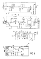
En référence à la figure 3, un circuit électronique de dispositif selon l'invention est représenté.With reference to FIG. 3, an electronic device circuit according to the invention is represented.
Les éléments représentés sont identiques ou fonctionnellement équivalents aux éléments représentés à la figure 2 et portent des chiffres de référence identiques.The elements shown are identical or functionally equivalent to the elements shown in FIG. 2 and bear identical reference numerals.
Ainsi, la photo diode 1 peut détecter des luminosités de valeurs comprises entre 170 KiloLux et 0.20 Lux, entre une luminosité maximale correspondant au plein soleil et une luminosité minimale correspondant à la pleine nuit.Thus, the
Le signal en provenance de la photopile 2 est tout d'abord amplifié par une succession 12 d'amplificateurs analogiques, avant d'être injecté sous forme de signal amplifié dans le microcontrôleur 14. Le signal provenant du microphone à électret 3 est également amplifié par une suite 13 d'amplificateurs analogiques, avant d'injecter le signal amplifié dans le microcontrôleur 14.The signal coming from the
Le microcontrôleur 14 comporte deux sorties distinctes dont l'activation est indiquée par l'allumage d'une diode électroluminescente 23 ou 24.The
Grâce au dispositif selon l'invention, la régulation de chauffage est automatiquement mise en mode de fonctionnement économique en l'absence effective de présence dans un local à chauffer.Thanks to the device according to the invention, the heating control is automatically put into economic operating mode in the absence of effective presence in a room to be heated.
L'invention décrite en référence à un mode de réalisation particulier n'y est nullement limitée, mais couvre au contraire toute modification de forme et toute variante de réalisation dans le cadre et l'esprit de l'invention.The invention described with reference to a particular embodiment is not limited thereto, but on the contrary covers any modification of form and any variant embodiment within the scope and spirit of the invention.
Le dispositif selon l'invention peut être installé en option d'un boîtier manuel de commande à distance, activable à tout moment par l'utilisateur, au même titre que les mode de fonctionnement économique, mode de confort, mode de programmation, mode de fonctionnement hors gel, arrêt.The device according to the invention can be optionally installed in a manual remote control unit, which can be activated at any time by the user, in the same way as the economy mode, the comfort mode, the programming mode, the mode of operation mode. frost-free operation, stop.
Le dispositif selon l'invention n'est actif que si l'utilisateur sélectionne ce mode sur son boîtier manuel de commande à distance.The device according to the invention is active only if the user selects this mode on its manual remote control box.
Le dispositif selon l'invention installé en option d'un boîtier manuel de commande à distance n'est pas prioritaire sur les ordres de mode de fonctionnement hors gel, ou d'arrêt.The device according to the invention optionally installed a manual remote control box is not a priority on frost-free mode or shutdown mode orders.
La détection de présence est permise par la juxtaposition d'au moins deux capteurs, dont la combinaison, selon la logique de détection décrite en référence à la figure 1, permet de savoir si la pièce est occupée.The detection of presence is permitted by the juxtaposition of at least two sensors, the combination of which, according to the detection logic described with reference to FIG. 1, makes it possible to know if the part is occupied.
De préférence, une lentille est utilisée pour élargir le champ de vision des capteurs de mouvement et de luminosité.Preferably, a lens is used to widen the field of view of the motion and brightness sensors.
Le capteur de mouvement est avantageusement un capteur infrarouge passif, constitué de deux photopiles physiquement distinctes et aptes à détecter les variations de rayonnement infrarouge incident, de surface inférieure à un cm2, et fonctionnant dans le spectre de détection correspondant au rayonnement infrarouge thermique (de 5 à 14µm de longueur d'onde).The motion sensor is advantageously a passive infrared sensor, consisting of two physically distinct solar cells capable of detecting variations in incident infrared radiation with a surface area of less than 1 cm 2 and operating in the detection spectrum corresponding to the thermal infrared radiation (from 5 to 14μm wavelength).
Le capteur de luminosité est avantageusement une cellule photoconductrice dont la résistance varie en fonction de la luminosité reçue, de surface inférieure à un cm2, et fonctionnant dans le spectre de détection correspondant au rayonnements visible, infrarouge proche, ultraviolet proche, de sensibilité proche de 0,2 Lux, et associé à un guide de lumière qui permet de capter et d'envoyer la lumière vers le capteur de luminosité.The brightness sensor is advantageously a photoconductive cell whose resistance varies as a function of the received brightness, with a surface area of less than one cm 2 , and operating in the detection spectrum corresponding to visible, near-infrared, near-ultraviolet radiation, with a sensitivity close to 0.2 Lux, and associated with a light guide that captures and sends light to the light sensor.
Afin de détecter au mieux les personnes présentes dans la pièce, on élargit avantageusement le champ de vision des capteurs, sans toutefois détecter les corps faisant moins de 60 cm de haut.In order to better detect the people present in the room, the field of view of the sensors is advantageously widened, without, however, detecting bodies that are less than 60 cm high.
La logique de fonctionnement d'un système de chauffage électrique peut avantageusement être séparée en deux logiques : une logique de détection et une logique de chauffage.The operating logic of an electric heating system can advantageously be separated into two logic: a detection logic and a heating logic.
La logique de détection de présence humaine associe, aux signaux des différents capteurs, un message : « présence » ou « absence ».The presence detection logic associates, with the signals of the various sensors, a message: "presence" or "absence".
La logique de chauffage adapte le mode de chauffage (typiquement mode de fonctionnement économique, mode de confort), d'une part, au message reçu : « présence » ou « absence », et d'autre part, au système de programmation et au temps écoulé depuis la dernière détection de présence.The heating logic adapts the heating mode (typically economical operating mode, comfort mode), on the one hand, to the received message: "presence" or "absence", and on the other hand, to the programming system and to the time elapsed since the last presence detection.
Dans la logique de détection, la détection de présence se fait grâce au capteur de luminosité dont le seuil est fixé entre 0.2 et 0.8 lux et au capteur infrarouge passif de mouvement.In the detection logic, the presence detection is done using the brightness sensor whose threshold is set between 0.2 and 0.8 lux and the passive infrared motion sensor.
Il faut que les deux conditions de luminosité et de mouvement soient réunies pour que l'utilisateur soit détecté et pour que l'appareil chauffe en mode de confort.It is necessary that the two conditions of luminosity and movement are brought together so that the user is detected and so that the apparatus heats in mode of comfort.
La logique de chauffage adapte la température de consigne en fonction du résultat de la détection (présence ou absence), de la plage de programmation (mode de fonctionnement économique, mode de confort), de la température de consigne de l'état précédent (Confort, Confort-1, Confort-2 ou Eco) et du temps écoulé depuis la dernière détection, depuis le début de la plage programmée en mode de confort.The heating logic adapts the setpoint temperature according to the detection result (presence or absence), the programming range (economical operating mode, comfort mode), the set temperature of the previous state (Comfort , Comfort-1, Comfort-2 or Eco) and the elapsed time since the last detection, from the beginning of the programmed range in comfort mode.
Une logique de chauffage préférée est commandée par l'automate suivant :

Ce schéma logique de chauffage correspond aux étapes suivantes :This heating logic diagram corresponds to the following steps:
Si l'on part de l'état E0, la température est en confort de par la programmation. L'appareil chauffe en confort pendant la durée d'anticipation Da pour préchauffer la pièce. Une fois ce temps écoulé, on passe en E1.If one starts from the state E0, the temperature is in comfort by the programming. The device heats comfortably during the Da anticipation period to preheat the room. Once this time has elapsed, we go to E1.
Si quelqu'un est détecté, on reste en confort. Si personne n'est détecté pendant un intervalle de temps ou durée de palier Dp, la transition progressive démarre : on passe en confort-1 (état E2) et l'horloge est remise à 0.If someone is detected, we stay in comfort. If no one is detected during a time interval or dwell time Dp, the progressive transition starts: one goes into comfort-1 (state E2) and the clock is reset to 0.
Depuis l'état E2, de la même façon, on passe en confort-2 (état E3, horloge remise à 0) au bout d'un temps ou durée de palier Dp si personne n'est détecté etc... jusqu'à arriver en température éco (E4).Since the state E2, in the same way, one passes in comfort-2 (state E3, clock reset to 0) after a time or duration of stage Dp if nobody is detected etc ... until arrive at the eco temperature (E4).
Bien sûr, si lors de cette phase descendante, quelqu'un est détecté, on repasse immédiatement en température de Confort (état E1).Of course, if during this downward phase, someone is detected, immediately returns to comfort temperature (E1 state).
D'autre part, si lors de cette phase descendante, l'ordre renvoyé par la programmation devient « Eco » (cas qui ne se produit que dans le choix d'une saisie classique), la transition progressive est court-circuitée et abrégée : on attend que le palier courant soit terminé (ie, on attend que l'horloge ait atteint la valeur de durée de palier Dp) puis on passe directement en Eco, comme l'indique le schéma suivant. Il s'agit des états intermédiaires E5, E6, et E7 du milieu.On the other hand, if during this downward phase, the order returned by the programming becomes "Eco" (a case that occurs only in the choice of a conventional input), the progressive transition is short-circuited and abbreviated: it is expected that the current plateau is completed (ie, it is expected that the clock has reached the step duration value Dp) and then goes directly to Eco, as shown in the following diagram. These are the intermediate states E5, E6, and E7 of the medium.
Si maintenant, l'on considère que l'on se situe dans une plage programmée en « Eco » : Si quelqu'un est détecté, la température de commande passe immédiatement en Confort (état E8). De la même façon que précédemment, si quelqu'un est détecté, on reste en confort. Si personne n'est détecté pendant un intervalle de temps ou durée de palier Dp, la transition progressive démarre comme précédemment : on passe en confort-1 (état E9) et l'horloge est remise à 0, puis en confort-2...If now, we consider that we are in a range programmed in "Eco": If someone is detected, the control temperature immediately passes Comfort (state E8). In the same way as before, if someone is detected, we stay in comfort. If no one is detected during a time interval or dwell time Dp, the progressive transition starts as before: one goes to comfort-1 (state E9) and the clock is reset to 0, then to comfort-2. .
Enfin, à tout moment, l'ordre renvoyé par la programmation peut devenir « Confort ». On revient alors à l'état E0.Finally, at any time, the order returned by the programming can become "Comfort". We then return to the state E0.
Claims (9)
Priority Applications (1)
| Application Number | Priority Date | Filing Date | Title |
|---|---|---|---|
| PL07290937T PL1884854T3 (en) | 2006-07-26 | 2007-07-25 | Device for heating premises |
Applications Claiming Priority (1)
| Application Number | Priority Date | Filing Date | Title |
|---|---|---|---|
| FR0606859A FR2904440B1 (en) | 2006-07-26 | 2006-07-26 | "HEATING DEVICE OF PREMISES" |
Publications (3)
| Publication Number | Publication Date |
|---|---|
| EP1884854A2 true EP1884854A2 (en) | 2008-02-06 |
| EP1884854A3 EP1884854A3 (en) | 2009-03-04 |
| EP1884854B1 EP1884854B1 (en) | 2011-04-27 |
Family
ID=37980011
Family Applications (1)
| Application Number | Title | Priority Date | Filing Date |
|---|---|---|---|
| EP07290937A Active EP1884854B1 (en) | 2006-07-26 | 2007-07-25 | Device for heating premises |
Country Status (4)
| Country | Link |
|---|---|
| EP (1) | EP1884854B1 (en) |
| ES (1) | ES2365792T3 (en) |
| FR (1) | FR2904440B1 (en) |
| PL (1) | PL1884854T3 (en) |
Cited By (2)
| Publication number | Priority date | Publication date | Assignee | Title |
|---|---|---|---|---|
| EP2367087A1 (en) | 2010-03-19 | 2011-09-21 | Thermor Pacific | Method of controlling a device and device adapted to carry out said method |
| FR2996035A1 (en) * | 2012-09-21 | 2014-03-28 | Thermor Pacific | Method for detection of presence of user for controlling and regulation of air conditioning/heating appliances, involves emitting presence detection signal when number of pixels has value greater or equal to reference value |
Citations (7)
| Publication number | Priority date | Publication date | Assignee | Title |
|---|---|---|---|---|
| US4223831A (en) | 1979-02-21 | 1980-09-23 | Szarka Jay R | Sound activated temperature control system |
| JPS60186630A (en) | 1984-03-05 | 1985-09-24 | Nippon Denso Co Ltd | Hot air space heater |
| GB2192080A (en) | 1986-06-27 | 1987-12-31 | Surrey County Council | Environmental control system eg for heating or lighting |
| US5100053A (en) | 1990-06-18 | 1992-03-31 | Whirlpool Corporation | Automatic set-back temperature control for air conditioners and the like |
| US5637040A (en) | 1995-04-13 | 1997-06-10 | Samsung Electronics Co., Ltd. | Infrared object detector |
| EP0802472A2 (en) | 1996-04-19 | 1997-10-22 | TrioVing a.s. | Environmental control lock system |
| FR2877111A3 (en) | 2004-10-25 | 2006-04-28 | Marsan Ind S A | Heat emitter for use in e.g. house, has proximity sensor and microprocessor being programmed to regulate heat energy obtained by heat emitter based on temperature of chamber and presence or absence of person in chamber |
Family Cites Families (1)
| Publication number | Priority date | Publication date | Assignee | Title |
|---|---|---|---|---|
| GB2382910B (en) * | 2000-08-04 | 2004-08-04 | Energy Technologies Group L L | Security and energy control system |
-
2006
- 2006-07-26 FR FR0606859A patent/FR2904440B1/en active Active
-
2007
- 2007-07-25 ES ES07290937T patent/ES2365792T3/en active Active
- 2007-07-25 EP EP07290937A patent/EP1884854B1/en active Active
- 2007-07-25 PL PL07290937T patent/PL1884854T3/en unknown
Patent Citations (7)
| Publication number | Priority date | Publication date | Assignee | Title |
|---|---|---|---|---|
| US4223831A (en) | 1979-02-21 | 1980-09-23 | Szarka Jay R | Sound activated temperature control system |
| JPS60186630A (en) | 1984-03-05 | 1985-09-24 | Nippon Denso Co Ltd | Hot air space heater |
| GB2192080A (en) | 1986-06-27 | 1987-12-31 | Surrey County Council | Environmental control system eg for heating or lighting |
| US5100053A (en) | 1990-06-18 | 1992-03-31 | Whirlpool Corporation | Automatic set-back temperature control for air conditioners and the like |
| US5637040A (en) | 1995-04-13 | 1997-06-10 | Samsung Electronics Co., Ltd. | Infrared object detector |
| EP0802472A2 (en) | 1996-04-19 | 1997-10-22 | TrioVing a.s. | Environmental control lock system |
| FR2877111A3 (en) | 2004-10-25 | 2006-04-28 | Marsan Ind S A | Heat emitter for use in e.g. house, has proximity sensor and microprocessor being programmed to regulate heat energy obtained by heat emitter based on temperature of chamber and presence or absence of person in chamber |
Cited By (3)
| Publication number | Priority date | Publication date | Assignee | Title |
|---|---|---|---|---|
| EP2367087A1 (en) | 2010-03-19 | 2011-09-21 | Thermor Pacific | Method of controlling a device and device adapted to carry out said method |
| FR2957691A1 (en) * | 2010-03-19 | 2011-09-23 | Thermor Pacific | METHOD OF CONTROLLING AN INSTALLATION AND INSTALLATION ADAPTED TO THE IMPLEMENTATION OF SAID METHOD |
| FR2996035A1 (en) * | 2012-09-21 | 2014-03-28 | Thermor Pacific | Method for detection of presence of user for controlling and regulation of air conditioning/heating appliances, involves emitting presence detection signal when number of pixels has value greater or equal to reference value |
Also Published As
| Publication number | Publication date |
|---|---|
| PL1884854T3 (en) | 2011-09-30 |
| FR2904440A1 (en) | 2008-02-01 |
| EP1884854A3 (en) | 2009-03-04 |
| FR2904440B1 (en) | 2010-10-22 |
| EP1884854B1 (en) | 2011-04-27 |
| ES2365792T3 (en) | 2011-10-11 |
Similar Documents
| Publication | Publication Date | Title |
|---|---|---|
| EP0116486B1 (en) | Electronic controller of the application of electric power to a temperature variation device | |
| EP2071309B1 (en) | Device for detecting infrared radiation comprising an imaging resistive bolometer, system comprising an array of such bolometers and method of reading an imaging bolometer integrated in such a system | |
| EP3111144A2 (en) | Communicating induction hotplate and method for seeking and monitoring a communicating culinary article on said plate | |
| EP1610590A1 (en) | Cooking hob with a plurality of cooking zones | |
| EP1884854B1 (en) | Device for heating premises | |
| FR2945608A1 (en) | Method for controlling cooking temperature of cooking utensil, involves controlling heating device based on heat command so that temperature at interior of cooking utensil converges towards setpoint temperature | |
| FR2554938A1 (en) | Method for regulating central heating installations and installations including the application thereof | |
| EP3571565B1 (en) | System for preconditioning an interior of a motor vehicle and associated management method | |
| CA2734665C (en) | Method for controlling an installation and equipment adapted to implement the method | |
| EP3184908B1 (en) | Method for regulating a heating device in accordance with the distance from same to an obstacle, and associated heating device | |
| EP0918266A1 (en) | Control device for motorised solar protection means | |
| CA2917963A1 (en) | Method for adjusting an electric heater in the event of a window being opened | |
| FR2786057A1 (en) | Warming device for infusion or transfusion fluid has heating plates divided into individually controlled heating zones with selective disconnection of heating current for one zone dependent on size of fluid bag | |
| FR2825164A1 (en) | TEMPERATURE COMPENSATION IN A TOASTER WITH ELECTRONIC CIRCUIT | |
| FR2903428A1 (en) | IRONING APPARATUS COMPRISING A SAFETY DEVICE AND METHOD OF SECURING A IRONING APPARATUS. | |
| FR2598528A1 (en) | METHOD FOR CONTROLLING THE TEMPERATURE OF A WORKPIECE AND DEVICE FOR CARRYING OUT SAID METHOD | |
| FR3031167A1 (en) | HEATING INSTALLATION MANAGEMENT METHOD AND CORRESPONDING HEATING PLANT | |
| FR2929020A1 (en) | DEVICE FORMING CONTROL THERMOSTAT | |
| FR2888427A1 (en) | Heating control method for electrical heating appliance e.g. radiator, involves displaying programmed and bidirectionally transmitted appliance configuration whose verification is interrogated by bidirectional infrared remote control module | |
| EP1199621B1 (en) | Temperature regulation process in an electric cooking oven | |
| EP2277090B1 (en) | Method for balancing the power of a heating device | |
| FR3061890A1 (en) | METHOD AND DEVICE FOR HEATING A VEHICLE ORGAN | |
| EP2188605B1 (en) | Bolometer with heat feedback | |
| FR3072157B1 (en) | RADIATOR COMPRISING AT LEAST TWO SEPARATE DRIVING MECHANISMS FOR PILOTTING THE SAME LIGHTING CONTROL PARAMETER | |
| FR3134212A1 (en) | METHOD FOR COUNTING PEOPLE AND DETERMINING THEIR POSITION IN A SPACE |
Legal Events
| Date | Code | Title | Description |
|---|---|---|---|
| PUAI | Public reference made under article 153(3) epc to a published international application that has entered the european phase |
Free format text: ORIGINAL CODE: 0009012 |
|
| AK | Designated contracting states |
Kind code of ref document: A2 Designated state(s): AT BE BG CH CY CZ DE DK EE ES FI FR GB GR HU IE IS IT LI LT LU LV MC MT NL PL PT RO SE SI SK TR |
|
| AX | Request for extension of the european patent |
Extension state: AL BA HR MK YU |
|
| PUAL | Search report despatched |
Free format text: ORIGINAL CODE: 0009013 |
|
| AK | Designated contracting states |
Kind code of ref document: A3 Designated state(s): AT BE BG CH CY CZ DE DK EE ES FI FR GB GR HU IE IS IT LI LT LU LV MC MT NL PL PT RO SE SI SK TR |
|
| AX | Request for extension of the european patent |
Extension state: AL BA HR MK RS |
|
| RAP1 | Party data changed (applicant data changed or rights of an application transferred) |
Owner name: THERMOR PACIFIC |
|
| 17P | Request for examination filed |
Effective date: 20090903 |
|
| 17Q | First examination report despatched |
Effective date: 20091006 |
|
| AKX | Designation fees paid |
Designated state(s): ES FR GB LT PL |
|
| RBV | Designated contracting states (corrected) |
Designated state(s): ES FR GB LT PL SE |
|
| REG | Reference to a national code |
Ref country code: DE Ref legal event code: 8566 |
|
| GRAP | Despatch of communication of intention to grant a patent |
Free format text: ORIGINAL CODE: EPIDOSNIGR1 |
|
| GRAS | Grant fee paid |
Free format text: ORIGINAL CODE: EPIDOSNIGR3 |
|
| GRAA | (expected) grant |
Free format text: ORIGINAL CODE: 0009210 |
|
| AK | Designated contracting states |
Kind code of ref document: B1 Designated state(s): ES FR GB LT PL SE |
|
| REG | Reference to a national code |
Ref country code: GB Ref legal event code: FG4D Free format text: NOT ENGLISH |
|
| REG | Reference to a national code |
Ref country code: SE Ref legal event code: TRGR |
|
| REG | Reference to a national code |
Ref country code: PL Ref legal event code: T3 |
|
| REG | Reference to a national code |
Ref country code: ES Ref legal event code: FG2A Ref document number: 2365792 Country of ref document: ES Kind code of ref document: T3 Effective date: 20111011 |
|
| PLBE | No opposition filed within time limit |
Free format text: ORIGINAL CODE: 0009261 |
|
| STAA | Information on the status of an ep patent application or granted ep patent |
Free format text: STATUS: NO OPPOSITION FILED WITHIN TIME LIMIT |
|
| 26N | No opposition filed |
Effective date: 20120130 |
|
| PGFP | Annual fee paid to national office [announced via postgrant information from national office to epo] |
Ref country code: LT Payment date: 20120622 Year of fee payment: 6 |
|
| PGFP | Annual fee paid to national office [announced via postgrant information from national office to epo] |
Ref country code: PL Payment date: 20120626 Year of fee payment: 6 |
|
| PGFP | Annual fee paid to national office [announced via postgrant information from national office to epo] |
Ref country code: GB Payment date: 20120719 Year of fee payment: 6 |
|
| PGFP | Annual fee paid to national office [announced via postgrant information from national office to epo] |
Ref country code: SE Payment date: 20130719 Year of fee payment: 7 |
|
| REG | Reference to a national code |
Ref country code: LT Ref legal event code: MM4D Effective date: 20130725 |
|
| GBPC | Gb: european patent ceased through non-payment of renewal fee |
Effective date: 20130725 |
|
| PG25 | Lapsed in a contracting state [announced via postgrant information from national office to epo] |
Ref country code: LT Free format text: LAPSE BECAUSE OF NON-PAYMENT OF DUE FEES Effective date: 20130725 Ref country code: GB Free format text: LAPSE BECAUSE OF NON-PAYMENT OF DUE FEES Effective date: 20130725 |
|
| REG | Reference to a national code |
Ref country code: PL Ref legal event code: LAPE |
|
| PG25 | Lapsed in a contracting state [announced via postgrant information from national office to epo] |
Ref country code: PL Free format text: LAPSE BECAUSE OF NON-PAYMENT OF DUE FEES Effective date: 20130725 |
|
| PGFP | Annual fee paid to national office [announced via postgrant information from national office to epo] |
Ref country code: ES Payment date: 20140728 Year of fee payment: 8 |
|
| REG | Reference to a national code |
Ref country code: SE Ref legal event code: EUG |
|
| PG25 | Lapsed in a contracting state [announced via postgrant information from national office to epo] |
Ref country code: SE Free format text: LAPSE BECAUSE OF NON-PAYMENT OF DUE FEES Effective date: 20140726 |
|
| REG | Reference to a national code |
Ref country code: FR Ref legal event code: PLFP Year of fee payment: 10 |
|
| PG25 | Lapsed in a contracting state [announced via postgrant information from national office to epo] |
Ref country code: ES Free format text: LAPSE BECAUSE OF NON-PAYMENT OF DUE FEES Effective date: 20150726 |
|
| REG | Reference to a national code |
Ref country code: FR Ref legal event code: PLFP Year of fee payment: 11 |
|
| REG | Reference to a national code |
Ref country code: FR Ref legal event code: CD Owner name: THERMOR, FR Effective date: 20171030 |
|
| REG | Reference to a national code |
Ref country code: ES Ref legal event code: FD2A Effective date: 20180705 |
|
| REG | Reference to a national code |
Ref country code: FR Ref legal event code: PLFP Year of fee payment: 12 |
|
| PGFP | Annual fee paid to national office [announced via postgrant information from national office to epo] |
Ref country code: FR Payment date: 20230725 Year of fee payment: 17 |