EP1883502B1 - Beam system membrane suspension for a motor mount - Google Patents
Beam system membrane suspension for a motor mount Download PDFInfo
- Publication number
- EP1883502B1 EP1883502B1 EP06758981.2A EP06758981A EP1883502B1 EP 1883502 B1 EP1883502 B1 EP 1883502B1 EP 06758981 A EP06758981 A EP 06758981A EP 1883502 B1 EP1883502 B1 EP 1883502B1
- Authority
- EP
- European Patent Office
- Prior art keywords
- beams
- motor
- resilient
- retaining ring
- suspension element
- Prior art date
- Legal status (The legal status is an assumption and is not a legal conclusion. Google has not performed a legal analysis and makes no representation as to the accuracy of the status listed.)
- Active
Links
Images


Classifications
-
- B—PERFORMING OPERATIONS; TRANSPORTING
- B25—HAND TOOLS; PORTABLE POWER-DRIVEN TOOLS; MANIPULATORS
- B25F—COMBINATION OR MULTI-PURPOSE TOOLS NOT OTHERWISE PROVIDED FOR; DETAILS OR COMPONENTS OF PORTABLE POWER-DRIVEN TOOLS NOT PARTICULARLY RELATED TO THE OPERATIONS PERFORMED AND NOT OTHERWISE PROVIDED FOR
- B25F5/00—Details or components of portable power-driven tools not particularly related to the operations performed and not otherwise provided for
- B25F5/006—Vibration damping means
-
- B—PERFORMING OPERATIONS; TRANSPORTING
- B25—HAND TOOLS; PORTABLE POWER-DRIVEN TOOLS; MANIPULATORS
- B25C—HAND-HELD NAILING OR STAPLING TOOLS; MANUALLY OPERATED PORTABLE STAPLING TOOLS
- B25C1/00—Hand-held nailing tools; Nail feeding devices
- B25C1/08—Hand-held nailing tools; Nail feeding devices operated by combustion pressure
Definitions
- the present invention relates generally to improvements in portable combustion-powered fastener driving tools, and specifically to improvements relating to the suspension of a motor for a combustion chamber fan for decreasing the operationally induced acceleration forces experienced by the motor, and for decreasing wear and tear on the motor.
- Such tools incorporate a generally pistol-shaped tool housing enclosing a small internal combustion engine that is powered by a fuel cell.
- a battery-powered electronic power distribution unit produces a spark for ignition, and a fan located in the combustion chamber provides for an efficient combustion within the chamber and facilitates scavenging, including the exhaust of combustion by-products.
- the engine includes a reciprocating piston with an elongated, rigid driver blade disposed within a cylindrical body.
- a valve sleeve is axially reciprocable about the cylinder and, through a linkage, moves to close the combustion chamber when a workpiece contact element at the end of the linkage is pressed against a workpiece. This pressing action also triggers a fuel-metering valve to introduce a specified volume of fuel into the closed combustion chamber.
- the piston and driver blade Upon the pulling of a trigger switch, which causes the ignition of a charge of gas in the combustion chamber of the engine, the piston and driver blade are shot downward to impact a positioned fastener and drive it into the workpiece. The piston then returns to its original, "ready” position, through differential gas pressures within the cylinder. Fasteners are fed into the nosepiece through a magazine, where they are held in a properly positioned orientation for receiving the impact of the driver blade.
- the combustion in the chamber causes the acceleration of the piston/driver blade assembly and the penetration of the fastener into the workpiece if the fastener is present.
- This combined downward movement causes a reactive force or recoil of the tool body. Therefore, the fan motor, which is suspended in the tool body, is subjected to an acceleration opposite the power stroke of the piston/driver blade and fastener.
- a bumper at the opposite end of the cylinder stops the momentum of the piston/driver blade assembly, and the tool body is accelerated toward the workpiece.
- the motor and shaft are thus subjected to an acceleration force which is opposite the direction of the first acceleration. After experiencing these reciprocal accelerations, the motor oscillates with respect to the tool.
- the above-listed objects are met or exceeded by the present suspension system for a motor of a combustion-powered tool having a cylinder head and a combustion chamber.
- the present suspension system provides an increased resistance to combustion-induced oscillations, and reduces the acceleration forces experienced by the motor during operation of the tool. Due to the reduction in acceleration forces, a less expensive and more standard motor can be used in the tool.
- the present suspension system includes a motor retaining ring defining a space for accepting the motor, an outer ring radially spaced from the retaining ring and configured for attachment to the cylinder head of the combustion chamber, and at least one resilient suspension element configured for dampening vibrations between a motor support and a tool frame.
- the resilient suspension element includes a plurality of resilient beams connecting the retaining ring and the outer ring.
- a suspension system for a motor of a combustion-powered hand tool having a cylinder head includes a flexible web disposed between the motor and the cylinder head.
- the flexible web includes at least one dampening structure configured for reducing a plurality of acceleration forces that result from operation of the tool.
- the flexible web further includes a plurality of generally linearly extending beams configured for defining a plurality of triangular recesses radially located on the web. The beams are configured to form a border between each of the plurality of triangular recesses.
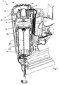
- a combustion-powered tool of the type suitable for use with the present invention is generally designated 10.
- the tool 10 has a housing 12 including a main power source chamber 14.
- a fan motor 22 is slidingly suspended within a depending cavity 24 in the center of the cylinder head 16 by a fan motor suspension system generally designated 26.
- the suspension system 26 includes a motor retaining ring 28 defining a space for accepting the motor 22, and an outer ring 30 radially spaced from the retaining ring.
- the outer ring 30 is configured for attachment to the cylinder head 16.
- At least one resilient suspension element 32 is configured for dampening vibrations and oscillations of the motor 22. Included in resilient suspension element 32 is a plurality of resilient beams 34 that are configured for connecting the retaining ring 28 and the outer ring 30.
- the motor retaining ring 28 has a top edge 36 and a bottom edge 38.
- a generally cylindrical sidewall 40 depends from the bottom edge 38 of the retaining ring, and a generally circular base 42 is formed at a bottom edge 44 of the sidewall.
- a bottom of the base 42 is generally planar, but includes a circular lip 46 generally centrally located on the base. The lip 46 defines a through-hole 48 that is configured for receiving a drive shaft 50 ( FIG. 1 ) of the motor 22.
- a chamber 52 for the motor 22 is defined by sidewall 40 and base 42.
- the motor 22 slidably fits into the chamber 52 and is held in place by a pair of screws (not shown) that are configured to be inserted into openings 53a and 53b, located in base 42. The screws are then tightened into corresponding openings (not shown) in the motor 22.
- the retaining ring 28 can have other shapes and components, depending on the size and shape of the combustion head chamber 20, as is known in the art. In combination, the retaining ring 28, the sidewall 40 and the base 42 form a cup-like motor retaining structure. While other types of fabrication are contemplated, it is preferred that the motor retaining structure be unitary.
- the motor retaining structure is preferably manufactured from a lightweight cost-effective metal alloy, such as steel, although it is appreciated that other materials may be used, as are known in the art. Also, the retaining ring 28 is generally manufactured by deep drawing, although it is appreciated that other means of manufacture are available.
- the outer ring 30 is radially spaced from the motor retaining ring 28 and includes an inwardly curved portion 54 that is configured for receiving a spark plug (not shown).
- the outer ring 30 also includes a pair of radially extending ears 56 located on opposite sides of the outer ring. In the present embodiment, the ears 56 are located directly opposite from each other and at an equal distance from the inwardly curved portion 54. However, it is contemplated that other arrangements for the ears 56 and the curved portion 54 are possible.
- the ears 56 are configured to be inserted into and removed from a pair of corresponding pockets or openings (not shown) in the cylinder head 16, thus orienting the suspension system 26 in the cylinder head. However, it is appreciated that other types of orientation are suitable, depending on the application.
- the outer ring 30 is preferably manufactured from a lightweight, cost-effective metal alloy such as steel, and has an approximate thickness of 4,064 mm (.160"). It is contemplated that the outer ring 30 is manufactured by stamping the steel. However, other manufacturing processes, materials and thicknesses are also contemplated to meet the needs of particular applications.
- the plurality of resilient beams 34 are configured to connect the retaining ring 28 and the outer ring 30.
- at least one of the plurality of resilient beams 34 is rectangular in cross-section (best seen in FIG. 5 ), has a thickness of 2,5908 mm (.102"), and has a width of between 0,762 mm (0.030") and 1,27 mm (.050").
- the desired thickness and desired width of the beams 34 optimizes the effective resiliency of the suspension system 26 and decreases the acceleration forces experienced by the system during operation of the tool 10. It is further contemplated that the reduced acceleration forces will reduce the cost of the motor 22 in the tool 10, decreasing the overall cost of the tool.
- the suspension element 32 further includes a flexible web 58 that is configured to separate the plurality of resilient beams 34 on an upper surface 60 of the web from the plurality of resilient beams on a lower surface 62 of the web.
- the beams 34 on the upper surface 60 of the web 58 are configured to be aligned with the beams on the lower surface 62 of the web.
- the beams 34 on the upper surface 60 and the beams on the lower surface 62 can have alternate relative arrangements.
- the flexible web 58 is preferably manufactured from Neoprene® rubber, as are the other components of the preferably unitary suspension element 32, and is molded to both an inner wall 64 and an outer wall 66 of the suspension element 32. It is contemplated that the rubber material will increase the resiliency of the suspension system 26 and decrease the effect of the acceleration forces acting on the motor 22 during operation. However, it is contemplated that other materials are available that would provide similar characteristics, as are known in the art.
- each of the plurality of beams 34 is arranged at either an acute or obtuse angle relative to a radius of the motor 22.
- the beams 34 are preferably arranged such that each of the beams forms an angle ⁇ of between 20-40° relative to the retaining ring 28.
- pairs of adjacent beams 34 converge toward the retaining ring 28. It is contemplated that this arrangement optimizes the effective length of the beams 34, thus increasing the resiliency of the suspension element 32.
- the beams 34 define a plurality of triangular recesses 68 located in a central annular groove portion 70 of the suspension element 32.
- the groove portion 70 is formed between the inner wall 64 and the outer wall 66 of the suspension element 32.
- the triangular recesses 68 are blind, in that they do not extend entirely through the groove portion 70. It is contemplated that the use of the blind recesses 68 prevents rubber flashings from forming during the manufacture of the suspension element 32 and falling into the tool 10 during operation.
- recesses 68 are formed in a triangular shape in the present embodiment, it is appreciated that other shapes of recesses may be formed depending on the arrangement of the rectangular beams 34.
- the recesses 68 in the present embodiment are preferably arranged in an offset pattern relative to each other. This offset pattern is a result of the arrangement of the rectangular beams 34 relative to the retaining ring 28.
- recesses 68i pointing towards the inner wall 64 of the suspension element 32 are larger than triangular recesses 68 pointing towards the outer wall 66 of the suspension element.
- the triangular recesses 68 could be arranged in an opposite orientation and the suspension system 26 would achieve the same results.
- the inner wall 64 of the suspension element 32 is configured to surround an outer edge 72 of the retaining ring 28, and is preferably attached to the outer edge of the retaining ring by means of vulcanization. However, other means of attachment are available, as are known in the art.
- the outer wall 66 of the suspension element 32 is configured to abut an inner edge 74 of the outer ring 30, and is also preferably attached to the inner edge of the outer ring by means of vulcanization. However, as indicated above, other means of attachment are available.
- the plurality of beams 34 connect the inner wall 64 to the outer wall 66, maintaining a connection between the retaining ring 28 and the outer ring 30. It is contemplated that manufacturing the suspension element 32 in unitary fashion out of Neoprene® rubber aids in increasing the resiliency of the system 26 and also decreases the acceleration forces that arise during operation of the tool 10.
- the outer wall 66 of the suspension element 32 includes an inwardly curved portion 76 that is configured to correspond to the curved portion 54 of the outer ring 30 for receiving a spark plug (not shown).
- the outer wall 66 of the suspension element 32 further includes a pair of ears 78 that are configured to correspond with the ears 56 of the outer ring 30.
- the corresponding ears 56, 78 are preferably located directly opposite and in registry with each other and are configured to orient the system 26 to the cylinder head 16. It is contemplated that other means for orienting the suspension system 26 to the cylinder head 16 are available, as are known in the art, and the features of the present embodiment are not limited to the configuration described above.
- the suspension element 32 further defines an opening 80 that is located diametrically opposite from the curved portion 76.
- the opening 80 interrupts the groove portion 70 of the suspension element 32, and therefore does not interrupt the continuity of the inner wall 64 or the outer wall 66 of the suspension element. It is contemplated that the opening 80 stabilizes the suspension system 26 because it offsets or balances the loss of suspension element material caused by the curved portion 76. More specifically, the curved portion 76 decreases the mass of the suspension element 32 on the curved portion end. As a result, it is contemplated that this arrangement stabilizes the system 26, preventing it from wobbling during operation of the tool 10.
- the present suspension system 26 accommodates the accelerations experienced by the motor 22 during operation of the tool 10.
- the ignition of combustible gases in the chamber 20 forces a piston 82 and an associated driver blade 83 ( FIG. 1 ) downwardly toward a workpiece (not shown)
- the tool 10 experiences a recoil force in the opposite direction.
- Both the motor 22, which is suspended by the suspension system 26 in the tool 10, and the drive shaft 50, are accelerated upwardly in the direction of the recoil of the tool by a force transmitted through the suspension system.
- the piston 82 bottoms-out in a cylinder 84 against a bumper 86, reducing the acceleration of the tool 10 towards the workpiece.
- the motor 22 and the drive shaft 50 are now accelerated in this new, opposite direction. These reciprocal accelerations repeat, and as a result, the motor 22 oscillates within the tool 10.
- the present suspension system 26 accommodates and resiliently dampens these reciprocal accelerations, thus preventing the motor 22 from excessive oscillation.
- An advantage of the present suspension system 26 is an increased resiliency or resistance to combustion-induced oscillations due to the arrangement and design of the plurality of beams 34 of the suspension element 32.
- the more resilient suspension system 26 is more flexible than prior art suspension systems, and provides properties for returning the motor 22 to its original operating position prior to the next use of the tool 10. It is also contemplated that this arrangement reduces the acceleration forces experienced by the motor 22 while the tool 10 is being operated, reducing the interior damage experienced by the motor. It is further contemplated that because of the decreased acceleration forces, a less expensive and more standard motor 22 can be utilized inside the tool 10, thereby increasing the cost-effectiveness of the tool.
Landscapes
- Engineering & Computer Science (AREA)
- Mechanical Engineering (AREA)
- Chemical & Material Sciences (AREA)
- Combustion & Propulsion (AREA)
- Portable Nailing Machines And Staplers (AREA)
- Vibration Prevention Devices (AREA)
- Springs (AREA)
Applications Claiming Priority (2)
| Application Number | Priority Date | Filing Date | Title |
|---|---|---|---|
| US11/122,353 US7107944B1 (en) | 2005-05-05 | 2005-05-05 | Beam system membrane suspension for a motor mount |
| PCT/US2006/016972 WO2006121726A2 (en) | 2005-05-05 | 2006-05-03 | Beam system membrane suspension for a motor mount |
Publications (2)
| Publication Number | Publication Date |
|---|---|
| EP1883502A2 EP1883502A2 (en) | 2008-02-06 |
| EP1883502B1 true EP1883502B1 (en) | 2018-11-07 |
Family
ID=36950142
Family Applications (1)
| Application Number | Title | Priority Date | Filing Date |
|---|---|---|---|
| EP06758981.2A Active EP1883502B1 (en) | 2005-05-05 | 2006-05-03 | Beam system membrane suspension for a motor mount |
Country Status (7)
| Country | Link |
|---|---|
| US (2) | US7107944B1 (enExample) |
| EP (1) | EP1883502B1 (enExample) |
| JP (2) | JP5107904B2 (enExample) |
| AU (2) | AU2006244507B2 (enExample) |
| CA (2) | CA2607361C (enExample) |
| NZ (1) | NZ563126A (enExample) |
| WO (1) | WO2006121726A2 (enExample) |
Families Citing this family (17)
| Publication number | Priority date | Publication date | Assignee | Title |
|---|---|---|---|---|
| JP2006255880A (ja) * | 2005-02-18 | 2006-09-28 | Hitachi Koki Co Ltd | 燃焼式動力工具 |
| JP4930670B2 (ja) * | 2005-04-01 | 2012-05-16 | マックス株式会社 | ガス燃焼式打込み工具のモータ保持機構 |
| TW201013055A (en) * | 2008-09-26 | 2010-04-01 | Basso Ind Corp | Motor fan device with shock-absorbing function |
| US9221112B2 (en) | 2010-03-10 | 2015-12-29 | Milwaukee Electric Tool Corporation | Motor mount for a power tool |
| AU2011201833A1 (en) * | 2011-04-21 | 2012-11-08 | Illinois Tool Works Inc. | Combustion powered tool assembly |
| US20140124231A1 (en) | 2012-11-06 | 2014-05-08 | Milwaukee Electric Tool Corporation | Electric motor for a power tool |
| US10432045B2 (en) | 2012-11-06 | 2019-10-01 | Milwaukee Electric Tool Corporation | Electric motor for a power tool |
| US10759031B2 (en) | 2014-08-28 | 2020-09-01 | Power Tech Staple and Nail, Inc. | Support for elastomeric disc valve in combustion driven fastener hand tool |
| US9862083B2 (en) | 2014-08-28 | 2018-01-09 | Power Tech Staple and Nail, Inc. | Vacuum piston retention for a combustion driven fastener hand tool |
| US10668608B2 (en) | 2016-02-10 | 2020-06-02 | Illinois Tool Works Inc. | Fastener driving tool |
| US10926391B2 (en) | 2017-11-14 | 2021-02-23 | Illinois Tool Works Inc. | Powered fastener driving tool having hook assemblies |
| USD855431S1 (en) | 2017-11-14 | 2019-08-06 | Illinois Tool Works Inc. | Fastener driving tool pipe hook |
| USD854820S1 (en) | 2017-11-14 | 2019-07-30 | Illinois Tool Works Inc. | Fastener driving tool belt hook |
| US11624314B2 (en) | 2018-08-21 | 2023-04-11 | Power Tech Staple and Nail, Inc. | Combustion chamber valve and fuel system for driven fastener hand tool |
| TWD203975S (zh) * | 2018-10-17 | 2020-04-11 | 大陸商歐品電子(昆山)有限公司 | 電路板(一) |
| TWD202850S (zh) * | 2018-10-17 | 2020-02-21 | 大陸商歐品電子(昆山)有限公司 | 電路板(二) |
| USD887358S1 (en) * | 2018-12-06 | 2020-06-16 | Lofelt Gmbh | Motor membrane |
Family Cites Families (10)
| Publication number | Priority date | Publication date | Assignee | Title |
|---|---|---|---|---|
| DE3035767A1 (de) * | 1980-09-23 | 1982-04-08 | Daimler-Benz Ag, 7000 Stuttgart | Schwingungstilger zur reduzierung von dreh- und biegeschwingungen einer welle |
| DE8907426U1 (de) * | 1989-06-19 | 1989-09-07 | Clouth Gummiwerke AG, 5000 Köln | Drehschwingungstilger |
| DE29706216U1 (de) * | 1997-04-08 | 1998-08-06 | ebm Werke GmbH & Co., 74673 Mulfingen | Anordnung zur schwingungsisolierenden Aufhängung eines Elektromotors |
| US6520397B1 (en) * | 1997-12-22 | 2003-02-18 | Illinois Tool Works Inc. | Combustion powered tool with improved combustion chamber fan motor suspension |
| DE19906585A1 (de) * | 1998-02-17 | 1999-08-26 | Motoren Ventilatoren Gmbh | Anordnung zur schwingungsgedämpften Halterung eines Elektromotors |
| JP2002034200A (ja) * | 2000-07-13 | 2002-01-31 | Asmo Co Ltd | モータの保持構造 |
| US6619527B1 (en) * | 2000-10-10 | 2003-09-16 | Illinois Tool Works Inc. | Combustion powered tool suspension for iron core fan motor |
| JP2003222190A (ja) * | 2002-01-25 | 2003-08-08 | Nok Corp | マウント |
| US7040520B2 (en) * | 2002-09-12 | 2006-05-09 | Illinois Tool Works Inc. | Fan motor suspension mount for a combustion-powered tool |
| DE202005011723U1 (de) | 2005-07-27 | 2005-10-06 | Joh. Friedrich Behrens Ag | Gasdrucknagler |
-
2005
- 2005-05-05 US US11/122,353 patent/US7107944B1/en not_active Expired - Lifetime
-
2006
- 2006-02-14 US US11/353,462 patent/US7140331B1/en active Active
- 2006-05-03 AU AU2006244507A patent/AU2006244507B2/en active Active
- 2006-05-03 CA CA2607361A patent/CA2607361C/en active Active
- 2006-05-03 WO PCT/US2006/016972 patent/WO2006121726A2/en not_active Ceased
- 2006-05-03 EP EP06758981.2A patent/EP1883502B1/en active Active
- 2006-05-03 CA CA2736819A patent/CA2736819C/en active Active
- 2006-05-03 NZ NZ563126A patent/NZ563126A/en unknown
- 2006-05-03 JP JP2008510160A patent/JP5107904B2/ja not_active Expired - Fee Related
-
2010
- 2010-09-27 AU AU2010224437A patent/AU2010224437B2/en active Active
-
2012
- 2012-04-10 JP JP2012089207A patent/JP5443535B2/ja not_active Expired - Fee Related
Non-Patent Citations (1)
| Title |
|---|
| None * |
Also Published As
| Publication number | Publication date |
|---|---|
| JP5443535B2 (ja) | 2014-03-19 |
| US7107944B1 (en) | 2006-09-19 |
| AU2006244507B2 (en) | 2010-07-01 |
| CA2607361C (en) | 2012-08-07 |
| AU2010224437B2 (en) | 2012-11-29 |
| WO2006121726A2 (en) | 2006-11-16 |
| NZ563126A (en) | 2010-12-24 |
| CA2607361A1 (en) | 2006-11-16 |
| EP1883502A2 (en) | 2008-02-06 |
| WO2006121726A3 (en) | 2007-01-11 |
| CA2736819C (en) | 2013-12-24 |
| AU2006244507A1 (en) | 2006-11-16 |
| AU2010224437A1 (en) | 2010-10-21 |
| JP2008540143A (ja) | 2008-11-20 |
| US20060249106A1 (en) | 2006-11-09 |
| JP5107904B2 (ja) | 2012-12-26 |
| US7140331B1 (en) | 2006-11-28 |
| CA2736819A1 (en) | 2006-11-16 |
| JP2012148403A (ja) | 2012-08-09 |
Similar Documents
| Publication | Publication Date | Title |
|---|---|---|
| AU2010224437B2 (en) | Beam system membrane suspension for a motor mount | |
| US6520397B1 (en) | Combustion powered tool with improved combustion chamber fan motor suspension | |
| JP5154723B2 (ja) | 鉄製コア式ファンモータ用燃焼動力式ツールサスペンション | |
| JP4426235B2 (ja) | 燃焼動力式工具内の燃焼室のファン用モータ用懸架機構 | |
| EP1954448B1 (en) | One way valve for combustion tool fan motor | |
| AU2012244211A1 (en) | Beam system membrane suspension for a motor mount | |
| WO2009079899A1 (fr) | Dispositif de réduction de vibrations de moteur de ventilateur pour cloueuse à combustible | |
| MXPA98010654A (es) | Herramienta accionada por combustion con suspension de motor de ventilador con camara de combustion mejorada |
Legal Events
| Date | Code | Title | Description |
|---|---|---|---|
| PUAI | Public reference made under article 153(3) epc to a published international application that has entered the european phase |
Free format text: ORIGINAL CODE: 0009012 |
|
| 17P | Request for examination filed |
Effective date: 20071205 |
|
| AK | Designated contracting states |
Kind code of ref document: A2 Designated state(s): AT BE BG CH CY CZ DE DK EE ES FI FR GB GR HU IE IS IT LI LT LU LV MC NL PL PT RO SE SI SK TR |
|
| 17Q | First examination report despatched |
Effective date: 20080403 |
|
| DAX | Request for extension of the european patent (deleted) | ||
| RAP1 | Party data changed (applicant data changed or rights of an application transferred) |
Owner name: ILLINOIS TOOL WORKS INC. |
|
| GRAP | Despatch of communication of intention to grant a patent |
Free format text: ORIGINAL CODE: EPIDOSNIGR1 |
|
| STAA | Information on the status of an ep patent application or granted ep patent |
Free format text: STATUS: GRANT OF PATENT IS INTENDED |
|
| INTG | Intention to grant announced |
Effective date: 20180606 |
|
| GRAS | Grant fee paid |
Free format text: ORIGINAL CODE: EPIDOSNIGR3 |
|
| GRAA | (expected) grant |
Free format text: ORIGINAL CODE: 0009210 |
|
| STAA | Information on the status of an ep patent application or granted ep patent |
Free format text: STATUS: THE PATENT HAS BEEN GRANTED |
|
| AK | Designated contracting states |
Kind code of ref document: B1 Designated state(s): AT BE BG CH CY CZ DE DK EE ES FI FR GB GR HU IE IS IT LI LT LU LV MC NL PL PT RO SE SI SK TR |
|
| REG | Reference to a national code |
Ref country code: GB Ref legal event code: FG4D |
|
| REG | Reference to a national code |
Ref country code: CH Ref legal event code: EP Ref country code: AT Ref legal event code: REF Ref document number: 1061504 Country of ref document: AT Kind code of ref document: T Effective date: 20181115 |
|
| REG | Reference to a national code |
Ref country code: IE Ref legal event code: FG4D |
|
| REG | Reference to a national code |
Ref country code: DE Ref legal event code: R096 Ref document number: 602006056766 Country of ref document: DE |
|
| REG | Reference to a national code |
Ref country code: SE Ref legal event code: TRGR |
|
| REG | Reference to a national code |
Ref country code: NL Ref legal event code: MP Effective date: 20181107 |
|
| REG | Reference to a national code |
Ref country code: LT Ref legal event code: MG4D |
|
| REG | Reference to a national code |
Ref country code: AT Ref legal event code: MK05 Ref document number: 1061504 Country of ref document: AT Kind code of ref document: T Effective date: 20181107 |
|
| PG25 | Lapsed in a contracting state [announced via postgrant information from national office to epo] |
Ref country code: IS Free format text: LAPSE BECAUSE OF FAILURE TO SUBMIT A TRANSLATION OF THE DESCRIPTION OR TO PAY THE FEE WITHIN THE PRESCRIBED TIME-LIMIT Effective date: 20190307 Ref country code: FI Free format text: LAPSE BECAUSE OF FAILURE TO SUBMIT A TRANSLATION OF THE DESCRIPTION OR TO PAY THE FEE WITHIN THE PRESCRIBED TIME-LIMIT Effective date: 20181107 Ref country code: AT Free format text: LAPSE BECAUSE OF FAILURE TO SUBMIT A TRANSLATION OF THE DESCRIPTION OR TO PAY THE FEE WITHIN THE PRESCRIBED TIME-LIMIT Effective date: 20181107 Ref country code: LV Free format text: LAPSE BECAUSE OF FAILURE TO SUBMIT A TRANSLATION OF THE DESCRIPTION OR TO PAY THE FEE WITHIN THE PRESCRIBED TIME-LIMIT Effective date: 20181107 Ref country code: ES Free format text: LAPSE BECAUSE OF FAILURE TO SUBMIT A TRANSLATION OF THE DESCRIPTION OR TO PAY THE FEE WITHIN THE PRESCRIBED TIME-LIMIT Effective date: 20181107 Ref country code: LT Free format text: LAPSE BECAUSE OF FAILURE TO SUBMIT A TRANSLATION OF THE DESCRIPTION OR TO PAY THE FEE WITHIN THE PRESCRIBED TIME-LIMIT Effective date: 20181107 Ref country code: BG Free format text: LAPSE BECAUSE OF FAILURE TO SUBMIT A TRANSLATION OF THE DESCRIPTION OR TO PAY THE FEE WITHIN THE PRESCRIBED TIME-LIMIT Effective date: 20190207 |
|
| PG25 | Lapsed in a contracting state [announced via postgrant information from national office to epo] |
Ref country code: PT Free format text: LAPSE BECAUSE OF FAILURE TO SUBMIT A TRANSLATION OF THE DESCRIPTION OR TO PAY THE FEE WITHIN THE PRESCRIBED TIME-LIMIT Effective date: 20190307 Ref country code: NL Free format text: LAPSE BECAUSE OF FAILURE TO SUBMIT A TRANSLATION OF THE DESCRIPTION OR TO PAY THE FEE WITHIN THE PRESCRIBED TIME-LIMIT Effective date: 20181107 Ref country code: GR Free format text: LAPSE BECAUSE OF FAILURE TO SUBMIT A TRANSLATION OF THE DESCRIPTION OR TO PAY THE FEE WITHIN THE PRESCRIBED TIME-LIMIT Effective date: 20190208 |
|
| PG25 | Lapsed in a contracting state [announced via postgrant information from national office to epo] |
Ref country code: CZ Free format text: LAPSE BECAUSE OF FAILURE TO SUBMIT A TRANSLATION OF THE DESCRIPTION OR TO PAY THE FEE WITHIN THE PRESCRIBED TIME-LIMIT Effective date: 20181107 Ref country code: PL Free format text: LAPSE BECAUSE OF FAILURE TO SUBMIT A TRANSLATION OF THE DESCRIPTION OR TO PAY THE FEE WITHIN THE PRESCRIBED TIME-LIMIT Effective date: 20181107 Ref country code: IT Free format text: LAPSE BECAUSE OF FAILURE TO SUBMIT A TRANSLATION OF THE DESCRIPTION OR TO PAY THE FEE WITHIN THE PRESCRIBED TIME-LIMIT Effective date: 20181107 Ref country code: DK Free format text: LAPSE BECAUSE OF FAILURE TO SUBMIT A TRANSLATION OF THE DESCRIPTION OR TO PAY THE FEE WITHIN THE PRESCRIBED TIME-LIMIT Effective date: 20181107 |
|
| REG | Reference to a national code |
Ref country code: DE Ref legal event code: R097 Ref document number: 602006056766 Country of ref document: DE |
|
| PG25 | Lapsed in a contracting state [announced via postgrant information from national office to epo] |
Ref country code: EE Free format text: LAPSE BECAUSE OF FAILURE TO SUBMIT A TRANSLATION OF THE DESCRIPTION OR TO PAY THE FEE WITHIN THE PRESCRIBED TIME-LIMIT Effective date: 20181107 Ref country code: RO Free format text: LAPSE BECAUSE OF FAILURE TO SUBMIT A TRANSLATION OF THE DESCRIPTION OR TO PAY THE FEE WITHIN THE PRESCRIBED TIME-LIMIT Effective date: 20181107 Ref country code: SK Free format text: LAPSE BECAUSE OF FAILURE TO SUBMIT A TRANSLATION OF THE DESCRIPTION OR TO PAY THE FEE WITHIN THE PRESCRIBED TIME-LIMIT Effective date: 20181107 |
|
| PLBE | No opposition filed within time limit |
Free format text: ORIGINAL CODE: 0009261 |
|
| STAA | Information on the status of an ep patent application or granted ep patent |
Free format text: STATUS: NO OPPOSITION FILED WITHIN TIME LIMIT |
|
| 26N | No opposition filed |
Effective date: 20190808 |
|
| PG25 | Lapsed in a contracting state [announced via postgrant information from national office to epo] |
Ref country code: SI Free format text: LAPSE BECAUSE OF FAILURE TO SUBMIT A TRANSLATION OF THE DESCRIPTION OR TO PAY THE FEE WITHIN THE PRESCRIBED TIME-LIMIT Effective date: 20181107 |
|
| REG | Reference to a national code |
Ref country code: DE Ref legal event code: R119 Ref document number: 602006056766 Country of ref document: DE |
|
| REG | Reference to a national code |
Ref country code: CH Ref legal event code: PL |
|
| PG25 | Lapsed in a contracting state [announced via postgrant information from national office to epo] |
Ref country code: LI Free format text: LAPSE BECAUSE OF NON-PAYMENT OF DUE FEES Effective date: 20190531 Ref country code: CH Free format text: LAPSE BECAUSE OF NON-PAYMENT OF DUE FEES Effective date: 20190531 Ref country code: MC Free format text: LAPSE BECAUSE OF FAILURE TO SUBMIT A TRANSLATION OF THE DESCRIPTION OR TO PAY THE FEE WITHIN THE PRESCRIBED TIME-LIMIT Effective date: 20181107 |
|
| REG | Reference to a national code |
Ref country code: BE Ref legal event code: MM Effective date: 20190531 |
|
| PG25 | Lapsed in a contracting state [announced via postgrant information from national office to epo] |
Ref country code: LU Free format text: LAPSE BECAUSE OF NON-PAYMENT OF DUE FEES Effective date: 20190503 |
|
| PG25 | Lapsed in a contracting state [announced via postgrant information from national office to epo] |
Ref country code: TR Free format text: LAPSE BECAUSE OF FAILURE TO SUBMIT A TRANSLATION OF THE DESCRIPTION OR TO PAY THE FEE WITHIN THE PRESCRIBED TIME-LIMIT Effective date: 20181107 |
|
| PG25 | Lapsed in a contracting state [announced via postgrant information from national office to epo] |
Ref country code: IE Free format text: LAPSE BECAUSE OF NON-PAYMENT OF DUE FEES Effective date: 20190503 Ref country code: DE Free format text: LAPSE BECAUSE OF NON-PAYMENT OF DUE FEES Effective date: 20191203 |
|
| PG25 | Lapsed in a contracting state [announced via postgrant information from national office to epo] |
Ref country code: BE Free format text: LAPSE BECAUSE OF NON-PAYMENT OF DUE FEES Effective date: 20190531 |
|
| PG25 | Lapsed in a contracting state [announced via postgrant information from national office to epo] |
Ref country code: FR Free format text: LAPSE BECAUSE OF NON-PAYMENT OF DUE FEES Effective date: 20190531 |
|
| PG25 | Lapsed in a contracting state [announced via postgrant information from national office to epo] |
Ref country code: CY Free format text: LAPSE BECAUSE OF FAILURE TO SUBMIT A TRANSLATION OF THE DESCRIPTION OR TO PAY THE FEE WITHIN THE PRESCRIBED TIME-LIMIT Effective date: 20181107 |
|
| PG25 | Lapsed in a contracting state [announced via postgrant information from national office to epo] |
Ref country code: HU Free format text: LAPSE BECAUSE OF FAILURE TO SUBMIT A TRANSLATION OF THE DESCRIPTION OR TO PAY THE FEE WITHIN THE PRESCRIBED TIME-LIMIT; INVALID AB INITIO Effective date: 20060503 |
|
| P01 | Opt-out of the competence of the unified patent court (upc) registered |
Effective date: 20230606 |
|
| PGFP | Annual fee paid to national office [announced via postgrant information from national office to epo] |
Ref country code: SE Payment date: 20240527 Year of fee payment: 19 |
|
| PGFP | Annual fee paid to national office [announced via postgrant information from national office to epo] |
Ref country code: GB Payment date: 20250527 Year of fee payment: 20 |