EP1882884A2 - Combustor liner with film cooling - Google Patents
Combustor liner with film cooling Download PDFInfo
- Publication number
- EP1882884A2 EP1882884A2 EP07112897A EP07112897A EP1882884A2 EP 1882884 A2 EP1882884 A2 EP 1882884A2 EP 07112897 A EP07112897 A EP 07112897A EP 07112897 A EP07112897 A EP 07112897A EP 1882884 A2 EP1882884 A2 EP 1882884A2
- Authority
- EP
- European Patent Office
- Prior art keywords
- holes
- liner
- longitudinal axis
- row
- combustor
- Prior art date
- Legal status (The legal status is an assumption and is not a legal conclusion. Google has not performed a legal analysis and makes no representation as to the accuracy of the status listed.)
- Withdrawn
Links
Images


Classifications
-
- F—MECHANICAL ENGINEERING; LIGHTING; HEATING; WEAPONS; BLASTING
- F23—COMBUSTION APPARATUS; COMBUSTION PROCESSES
- F23R—GENERATING COMBUSTION PRODUCTS OF HIGH PRESSURE OR HIGH VELOCITY, e.g. GAS-TURBINE COMBUSTION CHAMBERS
- F23R3/00—Continuous combustion chambers using liquid or gaseous fuel
- F23R3/02—Continuous combustion chambers using liquid or gaseous fuel characterised by the air-flow or gas-flow configuration
- F23R3/04—Air inlet arrangements
- F23R3/06—Arrangement of apertures along the flame tube
-
- F—MECHANICAL ENGINEERING; LIGHTING; HEATING; WEAPONS; BLASTING
- F23—COMBUSTION APPARATUS; COMBUSTION PROCESSES
- F23R—GENERATING COMBUSTION PRODUCTS OF HIGH PRESSURE OR HIGH VELOCITY, e.g. GAS-TURBINE COMBUSTION CHAMBERS
- F23R2900/00—Special features of, or arrangements for continuous combustion chambers; Combustion processes therefor
- F23R2900/03042—Film cooled combustion chamber walls or domes
-
- Y—GENERAL TAGGING OF NEW TECHNOLOGICAL DEVELOPMENTS; GENERAL TAGGING OF CROSS-SECTIONAL TECHNOLOGIES SPANNING OVER SEVERAL SECTIONS OF THE IPC; TECHNICAL SUBJECTS COVERED BY FORMER USPC CROSS-REFERENCE ART COLLECTIONS [XRACs] AND DIGESTS
- Y02—TECHNOLOGIES OR APPLICATIONS FOR MITIGATION OR ADAPTATION AGAINST CLIMATE CHANGE
- Y02T—CLIMATE CHANGE MITIGATION TECHNOLOGIES RELATED TO TRANSPORTATION
- Y02T50/00—Aeronautics or air transport
- Y02T50/60—Efficient propulsion technologies, e.g. for aircraft
-
- Y—GENERAL TAGGING OF NEW TECHNOLOGICAL DEVELOPMENTS; GENERAL TAGGING OF CROSS-SECTIONAL TECHNOLOGIES SPANNING OVER SEVERAL SECTIONS OF THE IPC; TECHNICAL SUBJECTS COVERED BY FORMER USPC CROSS-REFERENCE ART COLLECTIONS [XRACs] AND DIGESTS
- Y10—TECHNICAL SUBJECTS COVERED BY FORMER USPC
- Y10T—TECHNICAL SUBJECTS COVERED BY FORMER US CLASSIFICATION
- Y10T29/00—Metal working
- Y10T29/49—Method of mechanical manufacture
- Y10T29/49316—Impeller making
- Y10T29/4932—Turbomachine making
Definitions
- This invention relates generally to film cooled combustor liners for use in gas turbine engines, and more particularly, to such combustor liners having regions with closely spaced cooling holes.
- Combustors used in aircraft engines typically include inner and outer combustor liners to protect the combustor and surrounding engine components from the intense heat generated by the combustion process.
- a variety of approaches have been proposed to cool combustor liners so as to allow the liners to withstand greater combustion temperatures.
- One such approach is multi-hole film cooling wherein a thin layer of cooling air is provided along the combustion side of the liners by an array of very small cooling holes formed through the liners.
- Multi-hole film cooling reduces the overall thermal load on the liners because the mass flow through the cooling holes dilutes the hot combustion gas next to the liner surfaces, and the flow through the holes provides convective cooling of the liner walls.
- multi-hole film cooling is more difficult to design compared to pure nugget cooling due to the many restrictions associated with it, such as, the limitations on the spacing between holes, the number of holes in each row of multi-holes, the limitations on hole sizes, and difficulty of doing preferential cooling, for example.
- the holes should be spaced an adequate distance from each other to facilitate applying the thermal-barrier coating (TBC) to the combustor, and should also be spaced sufficiently close to each other to establish good film and convective cooling.
- TBC thermal-barrier coating
- At least one known combustor includes cooling holes that are spaced equidistantly in an axial direction and no attempt is made to control the circumferential spacing.
- the circumferential spacing may vary uncontrollably, resulting in liners having areas that are overcooled and other areas that are undercooled.
- circumferential preferential multihole cooling is difficult to fabricate because it requires variable circumferential spacing, which may cause interference among multihole rows.
- varying hole sizes is a possibility for circumferential preferential cooling, but it is relatively difficult to maintain the axial and circumferential distances between holes within the design limitations and also introduces additional cost.
- a combustor liner in one aspect, includes an upstream end and a downstream end having a longitudinal axis extending therethrough, and a plurality of cooling holes formed in the liner, the cooling holes arranged along the longitudinal axis into a plurality of circumferentially extending rows that are variably spaced apart along the longitudinal axis.
- a gas turbine engine assembly in another aspect, includes a compressor, and a combustor coupled in flow communication with said compressor, said combustor comprising at least one combustor liner having an upstream end and a downstream end having a longitudinal axis extending therethrough, and a plurality of cooling holes formed in said liner, said cooling holes arranged along the longitudinal axis into a plurality of circumferentially extending rows that are variably spaced apart along the longitudinal axis.
- a method of fabricating a gas turbine engine combustor liner includes providing a liner having an upstream end and a downstream end and having a longitudinal axis extending therethrough, and forming a plurality of cooling holes in the liner such that the plurality of holes are arranged along the longitudinal axis into a plurality of circumferentially extending rows that are variably spaced apart along the longitudinal axis.
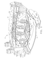
- FIG. 1 illustrates a combustor 10 of the type suitable for use in a gas turbine engine.
- Combustor 10 includes an outer liner 12 and an inner liner 14 disposed between an outer combustor casing 16 and an inner combustor casing 18.
- Outer and inner liners 12 and 14 are radially spaced from each other to define a combustion chamber 20.
- Outer liner 12 and outer casing 16 form an outer passage 22 therebetween, and inner liner 14 and inner casing 18 form an inner passage 24 therebetween.
- a cowl assembly 26 is mounted to the upstream ends of outer and inner liners 12 and 14.
- An annular opening 28 is formed in cowl assembly 26 for the introduction of compressed air into combustor 10.
- the compressed air is supplied from a compressor (not shown) in a direction generally indicated by arrow A of Figure 1.
- the compressed air passes principally through annular opening 28 to support combustion and partially into outer and inner passages 22 and 24 where it is used to cool the liners 12 and 14.
- annular dome plate 30 Disposed between and interconnecting the outer and inner liners 12 and 14 near their upstream ends is an annular dome plate 30.
- a plurality of circumferentially spaced swirler assemblies 32 are mounted in dome plate 30.
- Each swirler assembly 32 receives compressed air from annular opening 28 and fuel from a corresponding fuel nozzle 34. The fuel and air are swirled and mixed by swirler assemblies 32, and the resulting fuel/air mixture is discharged into combustion chamber 20.
- the combustor has an upstream end 60 and a downstream end 62 which define a longitudinal axis extending therethrough (not shown in Figure 1), which in the case of an annular combustor is coincident with the longitudinal axis of the engine.
- Figure 1 illustrates one preferred embodiment of a single annular combustor
- the present invention is equally applicable to any type of combustor, including double annular combustors, which uses multi-hole film cooling or can-annular combustors.
- Outer and inner liners 12 and 14 each comprise a single wall, metal shell having a generally annular and axially extending configuration.
- Outer liner 12 has a hot side 36 facing the hot combustion gases in combustion chamber 20 and a cold side 38 in contact with the relatively cool air in outer passage 22.
- inner liner 14 has a hot side 40 facing the hot combustion gases in combustion chamber 20 and a cold side 42 in contact with the relatively cool air in inner passage 24.
- Both liners 12 and 14 include a large number of closely spaced cooling holes 44 formed therein.
- Dilution air is introduced into combustor chamber 20 through a plurality of circumferentially spaced dilution holes 48 that are disposed in each of outer and inner liners 12 and 14.
- Dilution holes 48 are generally far smaller in number than the cooling holes 44, and each dilution hole 48 has a cross-sectional area that is substantially greater than the cross-sectional area of one of the cooling holes 44.
- Dilution holes 48 serve to admit dilution air into combustor chamber 20.
- the dilution holes are arranged in circumferentially extending bands or rows 50 around the periphery of the liners 12 and 14.
- the forward-most band of dilution holes 48 are referred to as primary dilution holes.
- certain ones of the primary dilution holes 48 are aligned with the injection points defined by the circumferential location of the center of the fuel nozzles 34 and swirlers 32.
- the flow of combustion gases past these circumferential locations may create "hot streaks" of locally increased material temperatures.
- These streaks are not strictly longitudinal; because of the swirl of the flow in the combustor caused by the swirlers 32, the streaks are curved in the circumferential direction when viewed along the length of the combustor.
- the prior art cooling provisions provide adequate cooling for the other portions of the combustor liners 12 and 14, the portions of the combustor liners 12 and 14 subject to hot streaks can exhibit oxidation, corrosion and low cycle fatigue (LCF) failures from field use.
- LCF low cycle fatigue
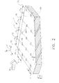
- FIG 2 depicts cooling holes in outer liner 12, it should be understood that the configuration of cooling holes of inner liner 14 is substantially identical to that of outer liner 12. As such, the following description will also apply to inner liner 14.
- Figure 2 includes a frame of reference having axes labeled X, Y and Z, wherein X is the downstream axial distance along the longitudinal axis 11 (also indicated by arrow B) of combustor 10, Y is the circumferential direction, and Z is a radial direction.
- Cooling holes 44 are axially slanted from cold side 38, to hot side 36 at a downstream angle A, which is preferably in the range of approximately 15 degrees to approximately 20 degrees. Cooling holes 44 are arranged in a series of circumferentially extending rows, 46, wherein adjacent holes 44 in each row have a circumferential hole spacing S, between their respective centerlines. Specifically, and in the exemplary embodiment, each respective cooling hole 44 has a diameter (d) and is separated in the circumferential direction (Y) by the distance (S) from adjacent cooling holes 44. As such, the exemplary combustor described herein includes cooling holes 44 that are all spaced apart approximately equidistantly in the circumferential direction, i.e. S is constant in the Y direction and have approximately the same diameter (d).
- the rows 46 of cooling holes 44 are variably spaced in the axial direction (X). More specifically, the cooling holes 44 are generally arranged into a plurality of rows 46 that include, for example, a first row 70, a second row 72, a third row 74, a fourth row 76, and an nth row 78 that are variably spaced axially through outer liner 12. As shown in Figure 2, first row 70 is formed a distance X 1 from second row 72, second row 72 is formed a distance X 2 from third row 74, third row 74 is formed a distance X 3 from fourth row 76, and fourth row 76 is formed a distance X N from nth row 78.
- the rows 46 of cooling holes 44 are axially spaced at various distances such as, for example, X 1 ⁇ X 2 ⁇ X 3 ⁇ X N to allow an increased flow of cooling air to be directed to an area of the combustor where increased cooling air is desired.
- Figure 3 illustrates the combustor liner 12 wherein the rows 46 of cooling holes 44 that are variably spaced apart to either increase or decrease the cooling airflow to selected portions of the combustor liner 12.
- Figure 4 is a graphical illustration of hole spacing along the longitudinal axis 11 that is discussed in conjunction with Figure 3 to illustrate the cooling hole spacing shown in Figure 3.
- a first group 80 of rows 46 are variably spaced such that the spacing X G1 between adjacent rows 46 is gradually decreasing in the axial direction (X) from the upstream end 60 of the combustor liner 12 at least partially rearwardly toward the downstream end 62 of the combustor liner 12.
- the row spacing X/d of the first group 80 is gradually decreasing, i.e. the rows are gradually spaced closer together, such that the cooling airflow supplied through the rows 46 of cooling holes in the first group 80 is gradually increasing to facilitate providing an increased flow of cooling air to potential hot spots that may occur upstream from the first row of dilution holes 48.
- a second group 82 of rows 46 are variably spaced such that the spacing X G2 between adjacent rows 46 is gradually increasing in the axial direction (X) from the first group of rows 80 formed through the combustor liner 12 at least partially rearwardly toward the downstream end 62 of the combustor liner 12.
- the row spacing X/d of the second group 82 is gradually increasing, i.e. the rows are gradually spaced further apart together, such that the cooling airflow supplied through the rows 46 of cooling holes in the second group 82 is gradually decreasing to facilitate providing a decreased flow of cooling air to areas of the combustion liner 12 which do not include potential hot spots.
- the third group 84 of rows 46 are variably spaced such that the spacing X G3 between adjacent rows 46 is gradually decreasing in the axial direction (X) from the second group 82 of cooling holes formed through the combustor liner 12 at least partially rearwardly toward the downstream end 62 of the combustor liner 12.
- the row spacing X/d of the third group 84 is gradually decreasing, i.e. the rows are gradually spaced closer together, between the rows of dilution holes 46 such that the cooling airflow supplied through the rows 46 of cooling holes in the third group 82 is gradually increasing to facilitate providing an increased flow of cooling air to potential hot spots that may occur between the rows of dilution holes 46.
- a fourth group 86 of rows 46 are variably spaced such that the spacing X G4 between adjacent rows 46 is gradually decreasing in the axial direction (X) from the third group 84 of cooling holes formed through the combustor liner 12 at least partially rearwardly toward the downstream end 62 of the combustor liner 12.
- the row spacing X/d of the fourth group 84 is gradually increasing, i.e. the rows are gradually spaced further apart, downstream from the dilution holes 46 such that the cooling airflow supplied through the rows 46 of cooling holes in the fourth group 82 is gradually decreasing in response to the decreased requirement for airflow cooling downstream from the dilution holes 46.
- a fifth group 88 of rows 46 are variably spaced such that the spacing X G5 between adjacent rows 46 is further increasing in the axial direction (X) downstream from the fourth group of holes 86 illustrating the further decrease in cooling requirements toward the downstream end 62 of combustor liner 12.
- a combustor liner that includes a plurality of rows of cooling holes that are variably spaced in the axial direction. More specifically, to facilitate increasing the multihole cooling at the axial stations that need more cooling, the axial spacing between at least some of rows 46 is varied. This is achieved by distributing the axial hole spacing (X/d) smoothly along the combustion liner in the axial direction (X), as shown in Figure 4, utilizing a smoothing function, such as a sine or linear function, for example. As such, the smoothing function facilitates minimizing any abrupt spacing changes between adjacent rows 46 of cooling holes 44.
- one smoothing function that may be utilized is Asin(Bx-C) where A, B, and C are chosen to taylor the hole spacing based on the location of the hot spots of the liner, although it should be realized that other smoothing functions may also be utilized.
- the number of multihole rows 46 and the number of holes 44 in each row 46 are chosen, along with the variable X/d functions, to control S/d, which is fixed for each row.
- a combination of complete X/d control and limited S/d control allows the designer to distribute the cooling air per unit area axially in any desired fashion.
- the design process also ensures that no interference occurs between adjacent holes 44 by calculating and constraining the aspect ratio of the hole spacing (S/x) to be preferably close to a value of one.
- S/x hole spacing
- only a single hole size is needed, which is a manufacturing convenience.
- the method of fabricating the liners described herein allows a limited controllable preferential cooling and eliminates the risk of the multihole interference.
- the method of fabricating the combustor liner includes providing a liner having an upstream end and a downstream end having a longitudinal axis extending therethrough, and forming a plurality of cooling holes in the liner such that the plurality of holes are arranged along the longitudinal axis into a plurality of circumferentially extending rows that are variably spaced apart along the longitudinal axis.
- the liner described herein enables using one multihole size for preferential cooling which is a design and manufacturing convenience.
- the liner described herein may be utilized with other means of preferential cooling, for example, multiple hole sizes.
Landscapes
- Engineering & Computer Science (AREA)
- Chemical & Material Sciences (AREA)
- Combustion & Propulsion (AREA)
- Mechanical Engineering (AREA)
- General Engineering & Computer Science (AREA)
- Turbine Rotor Nozzle Sealing (AREA)
- Gas Burners (AREA)
- Cylinder Crankcases Of Internal Combustion Engines (AREA)
- Spray-Type Burners (AREA)
Abstract
Description
- This invention relates generally to film cooled combustor liners for use in gas turbine engines, and more particularly, to such combustor liners having regions with closely spaced cooling holes.
- Combustors used in aircraft engines typically include inner and outer combustor liners to protect the combustor and surrounding engine components from the intense heat generated by the combustion process. A variety of approaches have been proposed to cool combustor liners so as to allow the liners to withstand greater combustion temperatures. One such approach is multi-hole film cooling wherein a thin layer of cooling air is provided along the combustion side of the liners by an array of very small cooling holes formed through the liners. Multi-hole film cooling reduces the overall thermal load on the liners because the mass flow through the cooling holes dilutes the hot combustion gas next to the liner surfaces, and the flow through the holes provides convective cooling of the liner walls.
- However, multi-hole film cooling is more difficult to design compared to pure nugget cooling due to the many restrictions associated with it, such as, the limitations on the spacing between holes, the number of holes in each row of multi-holes, the limitations on hole sizes, and difficulty of doing preferential cooling, for example. Specifically, to provide adequate cooling, the holes should be spaced an adequate distance from each other to facilitate applying the thermal-barrier coating (TBC) to the combustor, and should also be spaced sufficiently close to each other to establish good film and convective cooling.
- For example, to achieve adequate combustor cooling, at least one known combustor includes cooling holes that are spaced equidistantly in an axial direction and no attempt is made to control the circumferential spacing. However, since many liner contours have changing slopes, the circumferential spacing may vary uncontrollably, resulting in liners having areas that are overcooled and other areas that are undercooled. Moreover, circumferential preferential multihole cooling is difficult to fabricate because it requires variable circumferential spacing, which may cause interference among multihole rows. Additionally, varying hole sizes is a possibility for circumferential preferential cooling, but it is relatively difficult to maintain the axial and circumferential distances between holes within the design limitations and also introduces additional cost.
- Accordingly, there is a need for a combustor liner in which cooling film effectiveness is increased in the areas of the liner that are subject to unusually high temperatures and resulting material distress.
- In one aspect, a combustor liner is provided. The combustor liner includes an upstream end and a downstream end having a longitudinal axis extending therethrough, and a plurality of cooling holes formed in the liner, the cooling holes arranged along the longitudinal axis into a plurality of circumferentially extending rows that are variably spaced apart along the longitudinal axis.
- In another aspect, a gas turbine engine assembly is provided. The gas turbine engine assembly includes a compressor, and a combustor coupled in flow communication with said compressor, said combustor comprising at least one combustor liner having an upstream end and a downstream end having a longitudinal axis extending therethrough, and a plurality of cooling holes formed in said liner, said cooling holes arranged along the longitudinal axis into a plurality of circumferentially extending rows that are variably spaced apart along the longitudinal axis.
- In a further aspect, a method of fabricating a gas turbine engine combustor liner. The method includes providing a liner having an upstream end and a downstream end and having a longitudinal axis extending therethrough, and forming a plurality of cooling holes in the liner such that the plurality of holes are arranged along the longitudinal axis into a plurality of circumferentially extending rows that are variably spaced apart along the longitudinal axis.
- Embodiments of the present invention will now be described, by way of example only, with reference to the accompanying drawings, in which:
- Figure 1 is a cutaway perspective view of a gas turbine combustor having combustor liners of the present invention;
- Figure 2 is a perspective view of a portion of a combustor liner depicting angled multi-hole cooling holes;
- Figure 3 is a top view of a portion of a combustor liner depicting the arrangement of the multi-hole cooling holes of the present invention; and
- Figure 4 is a graphical illustration of the variably spaced rows of cooling holes shown in Figure 3.
- Figure 1 illustrates a
combustor 10 of the type suitable for use in a gas turbine engine. Combustor 10 includes anouter liner 12 and aninner liner 14 disposed between anouter combustor casing 16 and aninner combustor casing 18. Outer andinner liners combustion chamber 20.Outer liner 12 andouter casing 16 form anouter passage 22 therebetween, andinner liner 14 andinner casing 18 form aninner passage 24 therebetween. Acowl assembly 26 is mounted to the upstream ends of outer andinner liners annular opening 28 is formed incowl assembly 26 for the introduction of compressed air intocombustor 10. The compressed air is supplied from a compressor (not shown) in a direction generally indicated by arrow A of Figure 1. The compressed air passes principally throughannular opening 28 to support combustion and partially into outer andinner passages liners - Disposed between and interconnecting the outer and
inner liners annular dome plate 30. A plurality of circumferentially spacedswirler assemblies 32 are mounted indome plate 30. Eachswirler assembly 32 receives compressed air fromannular opening 28 and fuel from acorresponding fuel nozzle 34. The fuel and air are swirled and mixed byswirler assemblies 32, and the resulting fuel/air mixture is discharged intocombustion chamber 20. The combustor has anupstream end 60 and adownstream end 62 which define a longitudinal axis extending therethrough (not shown in Figure 1), which in the case of an annular combustor is coincident with the longitudinal axis of the engine. It is noted that although Figure 1 illustrates one preferred embodiment of a single annular combustor, the present invention is equally applicable to any type of combustor, including double annular combustors, which uses multi-hole film cooling or can-annular combustors. - Outer and
inner liners Outer liner 12 has ahot side 36 facing the hot combustion gases incombustion chamber 20 and acold side 38 in contact with the relatively cool air inouter passage 22. Similarly,inner liner 14 has ahot side 40 facing the hot combustion gases incombustion chamber 20 and acold side 42 in contact with the relatively cool air ininner passage 24. Bothliners cooling holes 44 formed therein. - Dilution air is introduced into
combustor chamber 20 through a plurality of circumferentially spaceddilution holes 48 that are disposed in each of outer andinner liners Dilution holes 48 are generally far smaller in number than thecooling holes 44, and eachdilution hole 48 has a cross-sectional area that is substantially greater than the cross-sectional area of one of thecooling holes 44.Dilution holes 48 serve to admit dilution air intocombustor chamber 20. The dilution holes are arranged in circumferentially extending bands orrows 50 around the periphery of theliners dilution holes 48 are referred to as primary dilution holes. - In the assembled combustor, certain ones of the
primary dilution holes 48 are aligned with the injection points defined by the circumferential location of the center of thefuel nozzles 34 andswirlers 32. In operation, the flow of combustion gases past these circumferential locations may create "hot streaks" of locally increased material temperatures. These streaks are not strictly longitudinal; because of the swirl of the flow in the combustor caused by theswirlers 32, the streaks are curved in the circumferential direction when viewed along the length of the combustor. Although the prior art cooling provisions provide adequate cooling for the other portions of thecombustor liners combustor liners - Referring now to Figure 2, wherein
cooling holes 44 that are disposed through a portion ofouter liner 12 are shown in more detail. Although Figure 2 depicts cooling holes inouter liner 12, it should be understood that the configuration of cooling holes ofinner liner 14 is substantially identical to that ofouter liner 12. As such, the following description will also apply toinner liner 14. Figure 2 includes a frame of reference having axes labeled X, Y and Z, wherein X is the downstream axial distance along the longitudinal axis 11 (also indicated by arrow B) ofcombustor 10, Y is the circumferential direction, and Z is a radial direction.Cooling holes 44 are axially slanted fromcold side 38, tohot side 36 at a downstream angle A, which is preferably in the range of approximately 15 degrees to approximately 20 degrees.Cooling holes 44 are arranged in a series of circumferentially extending rows, 46, whereinadjacent holes 44 in each row have a circumferential hole spacing S, between their respective centerlines. Specifically, and in the exemplary embodiment, eachrespective cooling hole 44 has a diameter (d) and is separated in the circumferential direction (Y) by the distance (S) fromadjacent cooling holes 44. As such, the exemplary combustor described herein includescooling holes 44 that are all spaced apart approximately equidistantly in the circumferential direction, i.e. S is constant in the Y direction and have approximately the same diameter (d). - In the exemplary embodiment, the
rows 46 ofcooling holes 44 are variably spaced in the axial direction (X). More specifically, thecooling holes 44 are generally arranged into a plurality ofrows 46 that include, for example, afirst row 70, asecond row 72, athird row 74, afourth row 76, and annth row 78 that are variably spaced axially throughouter liner 12. As shown in Figure 2,first row 70 is formed a distance X1 fromsecond row 72,second row 72 is formed a distance X2 fromthird row 74,third row 74 is formed a distance X3 fromfourth row 76, andfourth row 76 is formed a distance XN fromnth row 78. In the exemplary embodiment, therows 46 of cooling holes 44 are axially spaced at various distances such as, for example, X1 ≠ X2 ≠ X3 ≠ XN to allow an increased flow of cooling air to be directed to an area of the combustor where increased cooling air is desired. - For example, Figure 3 illustrates the
combustor liner 12 wherein therows 46 of cooling holes 44 that are variably spaced apart to either increase or decrease the cooling airflow to selected portions of thecombustor liner 12. Figure 4 is a graphical illustration of hole spacing along thelongitudinal axis 11 that is discussed in conjunction with Figure 3 to illustrate the cooling hole spacing shown in Figure 3. - In this embodiment, a
first group 80 ofrows 46 are variably spaced such that the spacing XG1 betweenadjacent rows 46 is gradually decreasing in the axial direction (X) from theupstream end 60 of thecombustor liner 12 at least partially rearwardly toward thedownstream end 62 of thecombustor liner 12. For example, as shown in Figure 4, the row spacing X/d of thefirst group 80 is gradually decreasing, i.e. the rows are gradually spaced closer together, such that the cooling airflow supplied through therows 46 of cooling holes in thefirst group 80 is gradually increasing to facilitate providing an increased flow of cooling air to potential hot spots that may occur upstream from the first row of dilution holes 48. - A
second group 82 ofrows 46 are variably spaced such that the spacing XG2 betweenadjacent rows 46 is gradually increasing in the axial direction (X) from the first group ofrows 80 formed through thecombustor liner 12 at least partially rearwardly toward thedownstream end 62 of thecombustor liner 12. For example, as shown in Figure 4, the row spacing X/d of thesecond group 82 is gradually increasing, i.e. the rows are gradually spaced further apart together, such that the cooling airflow supplied through therows 46 of cooling holes in thesecond group 82 is gradually decreasing to facilitate providing a decreased flow of cooling air to areas of thecombustion liner 12 which do not include potential hot spots. - The
third group 84 ofrows 46 are variably spaced such that the spacing XG3 betweenadjacent rows 46 is gradually decreasing in the axial direction (X) from thesecond group 82 of cooling holes formed through thecombustor liner 12 at least partially rearwardly toward thedownstream end 62 of thecombustor liner 12. For example, as shown in Figure 4, the row spacing X/d of thethird group 84 is gradually decreasing, i.e. the rows are gradually spaced closer together, between the rows of dilution holes 46 such that the cooling airflow supplied through therows 46 of cooling holes in thethird group 82 is gradually increasing to facilitate providing an increased flow of cooling air to potential hot spots that may occur between the rows of dilution holes 46. - A
fourth group 86 ofrows 46 are variably spaced such that the spacing XG4 betweenadjacent rows 46 is gradually decreasing in the axial direction (X) from thethird group 84 of cooling holes formed through thecombustor liner 12 at least partially rearwardly toward thedownstream end 62 of thecombustor liner 12. For example, as shown in Figure 4, the row spacing X/d of thefourth group 84 is gradually increasing, i.e. the rows are gradually spaced further apart, downstream from the dilution holes 46 such that the cooling airflow supplied through therows 46 of cooling holes in thefourth group 82 is gradually decreasing in response to the decreased requirement for airflow cooling downstream from the dilution holes 46. Moreover, afifth group 88 ofrows 46 are variably spaced such that the spacing XG5 betweenadjacent rows 46 is further increasing in the axial direction (X) downstream from the fourth group ofholes 86 illustrating the further decrease in cooling requirements toward thedownstream end 62 ofcombustor liner 12. - Described herein, a combustor liner that includes a plurality of rows of cooling holes that are variably spaced in the axial direction. More specifically, to facilitate increasing the multihole cooling at the axial stations that need more cooling, the axial spacing between at least some of
rows 46 is varied. This is achieved by distributing the axial hole spacing (X/d) smoothly along the combustion liner in the axial direction (X), as shown in Figure 4, utilizing a smoothing function, such as a sine or linear function, for example. As such, the smoothing function facilitates minimizing any abrupt spacing changes betweenadjacent rows 46 of cooling holes 44. For example, one smoothing function that may be utilized is Asin(Bx-C) where A, B, and C are chosen to taylor the hole spacing based on the location of the hot spots of the liner, although it should be realized that other smoothing functions may also be utilized. - Moreover, the number of
multihole rows 46 and the number ofholes 44 in eachrow 46 are chosen, along with the variable X/d functions, to control S/d, which is fixed for each row. A combination of complete X/d control and limited S/d control allows the designer to distribute the cooling air per unit area axially in any desired fashion. The design process also ensures that no interference occurs betweenadjacent holes 44 by calculating and constraining the aspect ratio of the hole spacing (S/x) to be preferably close to a value of one. Furthermore, with a smooth axial multihole spacing, only a single hole size is needed, which is a manufacturing convenience. Additionally, the method of fabricating the liners described herein allows a limited controllable preferential cooling and eliminates the risk of the multihole interference. It also provides an axially variable cooling air per unit area to target hot spots or control the liner profile and reduces cost of both design and manufacturing processes. This method has been demonstrated using computational-fluid dynamics (CFD). It was demonstrated that preferential cooling helped to reduce hot-spot gas temperatures locally. The success of the above-described concept was demonstrated in a highpressure sector combustor rig and a full-annular combustor rig. - The method of fabricating the combustor liner includes providing a liner having an upstream end and a downstream end having a longitudinal axis extending therethrough, and forming a plurality of cooling holes in the liner such that the plurality of holes are arranged along the longitudinal axis into a plurality of circumferentially extending rows that are variably spaced apart along the longitudinal axis. As such, the liner described herein enables using one multihole size for preferential cooling which is a design and manufacturing convenience. However, it should be realized that the liner described herein may be utilized with other means of preferential cooling, for example, multiple hole sizes.
- The foregoing has described a multi-hole film cooled combustor liner having an improved arrangement of cooling holes to reduce temperature, temperature gradients, and hot streaks within the combustor. While the invention has been described in terms of various specific embodiments, those skilled in the art will recognize that the invention can be practiced with modification within the spirit and scope of the claims.
Claims (10)
- A combustor liner (12, 14) comprising:a liner comprising an upstream end (60) and a downstream end (62) having a longitudinal axis (11) extending therethrough; anda plurality of cooling holes (44) formed in said liner, said cooling holes arranged along the longitudinal axis into a plurality of circumferentially extending rows (46) that are variably spaced apart along the longitudinal axis.
- The combustor liner (12, 14) in accordance with Claim 1, wherein said plurality of cooling holes (44) each have the same diameter.
- The combustor liner (12, 14) in accordance with Claim 1, wherein said plurality of cooling holes (44) are equidistantly spaced in a circumferential direction within a single row (46).
- The combustor liner (12, 14) in accordance with Claim 1, wherein said rows (46) of cooling holes (44) are arranged in at least one group (80, 82, 84, 86, 88), the axial spacing between adjacent rows gradually increasing in a downstream direction along the longitudinal axis (11).
- The combustor liner (12, 14) in accordance with Claim 1, wherein said plurality of cooling holes (44) are axially slanted at an angle that is between approximately fifteen degrees and approximately twenty degrees.
- The combustor liner (12, 14) in accordance with Claim 1, wherein said plurality of cooling holes (44) are arranged along the longitudinal axis (11) into a plurality of circumferentially extending rows (46) that are variably spaced apart along the longitudinal axis such that the spacing is gradually decreasing from the liner the upstream end (60) at least partially towards the liner downstream end (62).
- The combustor liner (12, 14) in accordance with Claim 1, further comprising:a first row (50) of dilution holes (48);
a second row of dilution holes formed downstream from said first row of dilution holes, said plurality of cooling holes (44) are arranged along the longitudinal axis (11) into a plurality of circumferentially extending rows (46) between said first and second rows of dilution holes and variably spaced apart along the longitudinal axis such that the spacing is gradually increasing from the first row of dilution holes downstream to the second row of dilution holes. - The combustor liner (12, 14) in accordance with Claim 1, further comprising:a first row (50) of dilution holes (48);a second row of dilution holes downstream from said first row of dilution holes, said plurality of cooling holes (44) are arranged along the longitudinal axis (11) into a plurality of circumferentially extending rows (46) between said first and second rows of dilution holes and variably spaced apart along the longitudinal axis such that the spacing is gradually decreasing from the first row of dilution holes downstream to the second row of dilution holes.
- A gas turbine engine assembly comprising:a compressor; anda combustor (10) coupled in flow communication with said compressor, said combustor comprising at least one combustor liner (12, 14) having an upstream end (60) and a downstream end (62) having a longitudinal axis (11) extending therethrough, and a plurality of cooling holes (44) formed in said liner, said cooling holes arranged along the longitudinal axis into a plurality of circumferentially extending rows (46) that are variably spaced apart along the longitudinal axis.
- The gas turbine engine assembly in accordance with Claim 9, wherein said plurality of cooling holes (44) each have the same diameter.
Applications Claiming Priority (1)
| Application Number | Priority Date | Filing Date | Title |
|---|---|---|---|
| US11/460,114 US7669422B2 (en) | 2006-07-26 | 2006-07-26 | Combustor liner and method of fabricating same |
Publications (2)
| Publication Number | Publication Date |
|---|---|
| EP1882884A2 true EP1882884A2 (en) | 2008-01-30 |
| EP1882884A3 EP1882884A3 (en) | 2015-08-05 |
Family
ID=38582275
Family Applications (1)
| Application Number | Title | Priority Date | Filing Date |
|---|---|---|---|
| EP07112897.9A Withdrawn EP1882884A3 (en) | 2006-07-26 | 2007-07-20 | Combustor liner with film cooling |
Country Status (4)
| Country | Link |
|---|---|
| US (1) | US7669422B2 (en) |
| EP (1) | EP1882884A3 (en) |
| JP (2) | JP5224742B2 (en) |
| CN (1) | CN101113820B (en) |
Families Citing this family (28)
| Publication number | Priority date | Publication date | Assignee | Title |
|---|---|---|---|---|
| US8171634B2 (en) | 2007-07-09 | 2012-05-08 | Pratt & Whitney Canada Corp. | Method of producing effusion holes |
| US7905094B2 (en) * | 2007-09-28 | 2011-03-15 | Honeywell International Inc. | Combustor systems with liners having improved cooling hole patterns |
| ATE554346T1 (en) * | 2009-03-16 | 2012-05-15 | Alstom Technology Ltd | BURNER FOR A GAS TURBINE AND METHOD FOR THE LOCAL COOLING OF HOT GAS STREAMS PASSING THROUGH A BURNER |
| FR2953907B1 (en) * | 2009-12-11 | 2012-11-02 | Snecma | COMBUSTION CHAMBER FOR TURBOMACHINE |
| FR2982008B1 (en) * | 2011-10-26 | 2013-12-13 | Snecma | ANNULAR ROOM OF COMBUSTION CHAMBER WITH IMPROVED COOLING AT THE PRIMARY HOLES AND DILUTION HOLES |
| US9133724B2 (en) | 2012-01-09 | 2015-09-15 | General Electric Company | Turbomachine component including a cover plate |
| US8864445B2 (en) | 2012-01-09 | 2014-10-21 | General Electric Company | Turbine nozzle assembly methods |
| US9011079B2 (en) | 2012-01-09 | 2015-04-21 | General Electric Company | Turbine nozzle compartmentalized cooling system |
| US9039350B2 (en) | 2012-01-09 | 2015-05-26 | General Electric Company | Impingement cooling system for use with contoured surfaces |
| US8944751B2 (en) | 2012-01-09 | 2015-02-03 | General Electric Company | Turbine nozzle cooling assembly |
| US9011078B2 (en) | 2012-01-09 | 2015-04-21 | General Electric Company | Turbine vane seal carrier with slots for cooling and assembly |
| US20130318991A1 (en) * | 2012-05-31 | 2013-12-05 | General Electric Company | Combustor With Multiple Combustion Zones With Injector Placement for Component Durability |
| WO2015030927A1 (en) | 2013-08-30 | 2015-03-05 | United Technologies Corporation | Contoured dilution passages for a gas turbine engine combustor |
| WO2015126501A2 (en) | 2013-12-06 | 2015-08-27 | United Technologies Corporation | Co-swirl orientation of combustor effusion passages for gas turbine engine combustor |
| US10934853B2 (en) | 2014-07-03 | 2021-03-02 | Rolls-Royce Corporation | Damage tolerant cooling of high temperature mechanical system component including a coating |
| DE102014214981B3 (en) * | 2014-07-30 | 2015-12-24 | Siemens Aktiengesellschaft | Side-coated heat shield element with impingement cooling on open spaces |
| WO2016039745A1 (en) * | 2014-09-11 | 2016-03-17 | Siemens Energy, Inc. | Syngas burner system for a gas turbine engine |
| CN104791848A (en) * | 2014-11-25 | 2015-07-22 | 西北工业大学 | Combustion chamber flame cylinder wall face with blade grid channel multi-inclined-hole cooling manner adopted |
| CN104863750B (en) * | 2015-05-07 | 2017-05-17 | 南京航空航天大学 | Impingement and air-film cooling structure adopting variable-hole array pitches used for wall surface of jet tube |
| US10670267B2 (en) * | 2015-08-14 | 2020-06-02 | Raytheon Technologies Corporation | Combustor hole arrangement for gas turbine engine |
| US10041677B2 (en) * | 2015-12-17 | 2018-08-07 | General Electric Company | Combustion liner for use in a combustor assembly and method of manufacturing |
| DE102016201452A1 (en) * | 2016-02-01 | 2017-08-03 | Rolls-Royce Deutschland Ltd & Co Kg | Gas turbine combustor with wall contouring |
| US20180266687A1 (en) * | 2017-03-16 | 2018-09-20 | General Electric Company | Reducing film scrubbing in a combustor |
| KR101906051B1 (en) | 2017-05-08 | 2018-10-08 | 두산중공업 주식회사 | combustor and gas turbine comprising it and method of distributing compressed air using it |
| US11029027B2 (en) * | 2018-10-03 | 2021-06-08 | Raytheon Technologies Corporation | Dilution/effusion hole pattern for thick combustor panels |
| CN109668173B (en) * | 2019-01-14 | 2019-11-26 | 西安增材制造国家研究院有限公司 | A kind of evaporation tubular type compact combustion chamber |
| DE102019105442A1 (en) * | 2019-03-04 | 2020-09-10 | Rolls-Royce Deutschland Ltd & Co Kg | Method for producing an engine component with a cooling duct arrangement and engine component |
| CN116202106B (en) * | 2023-03-08 | 2024-05-03 | 中国科学院工程热物理研究所 | Engine combustion chamber flame tube structure with coupling design of air film holes and blending holes |
Citations (1)
| Publication number | Priority date | Publication date | Assignee | Title |
|---|---|---|---|---|
| US6205789B1 (en) * | 1998-11-13 | 2001-03-27 | General Electric Company | Multi-hole film cooled combuster liner |
Family Cites Families (17)
| Publication number | Priority date | Publication date | Assignee | Title |
|---|---|---|---|---|
| US3623711A (en) * | 1970-07-13 | 1971-11-30 | Avco Corp | Combustor liner cooling arrangement |
| JPH0752014B2 (en) * | 1986-03-20 | 1995-06-05 | 株式会社日立製作所 | Gas turbine combustor |
| US5233828A (en) * | 1990-11-15 | 1993-08-10 | General Electric Company | Combustor liner with circumferentially angled film cooling holes |
| CA2056592A1 (en) * | 1990-12-21 | 1992-06-22 | Phillip D. Napoli | Multi-hole film cooled combustor liner with slotted film starter |
| GB9127505D0 (en) * | 1991-03-11 | 2013-12-25 | Gen Electric | Multi-hole film cooled afterburner combustor liner |
| US5241827A (en) * | 1991-05-03 | 1993-09-07 | General Electric Company | Multi-hole film cooled combuster linear with differential cooling |
| FR2714154B1 (en) * | 1993-12-22 | 1996-01-19 | Snecma | Combustion chamber comprising a wall provided with multi-perforation. |
| US5850732A (en) * | 1997-05-13 | 1998-12-22 | Capstone Turbine Corporation | Low emissions combustion system for a gas turbine engine |
| US6192689B1 (en) * | 1998-03-18 | 2001-02-27 | General Electric Company | Reduced emissions gas turbine combustor |
| US6145319A (en) * | 1998-07-16 | 2000-11-14 | General Electric Company | Transitional multihole combustion liner |
| US6408629B1 (en) * | 2000-10-03 | 2002-06-25 | General Electric Company | Combustor liner having preferentially angled cooling holes |
| US6513331B1 (en) * | 2001-08-21 | 2003-02-04 | General Electric Company | Preferential multihole combustor liner |
| US7086232B2 (en) * | 2002-04-29 | 2006-08-08 | General Electric Company | Multihole patch for combustor liner of a gas turbine engine |
| US7093439B2 (en) * | 2002-05-16 | 2006-08-22 | United Technologies Corporation | Heat shield panels for use in a combustor for a gas turbine engine |
| US7036316B2 (en) * | 2003-10-17 | 2006-05-02 | General Electric Company | Methods and apparatus for cooling turbine engine combustor exit temperatures |
| US7010921B2 (en) * | 2004-06-01 | 2006-03-14 | General Electric Company | Method and apparatus for cooling combustor liner and transition piece of a gas turbine |
| US7614235B2 (en) * | 2005-03-01 | 2009-11-10 | United Technologies Corporation | Combustor cooling hole pattern |
-
2006
- 2006-07-26 US US11/460,114 patent/US7669422B2/en active Active
-
2007
- 2007-07-20 EP EP07112897.9A patent/EP1882884A3/en not_active Withdrawn
- 2007-07-20 JP JP2007188925A patent/JP5224742B2/en not_active Expired - Fee Related
- 2007-07-26 CN CN2007101369988A patent/CN101113820B/en active Active
-
2013
- 2013-03-13 JP JP2013050194A patent/JP5475901B2/en not_active Expired - Fee Related
Patent Citations (1)
| Publication number | Priority date | Publication date | Assignee | Title |
|---|---|---|---|---|
| US6205789B1 (en) * | 1998-11-13 | 2001-03-27 | General Electric Company | Multi-hole film cooled combuster liner |
Also Published As
| Publication number | Publication date |
|---|---|
| CN101113820B (en) | 2011-12-28 |
| EP1882884A3 (en) | 2015-08-05 |
| JP2008032386A (en) | 2008-02-14 |
| CN101113820A (en) | 2008-01-30 |
| JP5475901B2 (en) | 2014-04-16 |
| US7669422B2 (en) | 2010-03-02 |
| JP5224742B2 (en) | 2013-07-03 |
| US20100011773A1 (en) | 2010-01-21 |
| JP2013108751A (en) | 2013-06-06 |
Similar Documents
| Publication | Publication Date | Title |
|---|---|---|
| US7669422B2 (en) | Combustor liner and method of fabricating same | |
| US6513331B1 (en) | Preferential multihole combustor liner | |
| US6205789B1 (en) | Multi-hole film cooled combuster liner | |
| US8544277B2 (en) | Turbulated aft-end liner assembly and cooling method | |
| EP0512670B1 (en) | Multi-hole film cooled combustor liner with preferential cooling | |
| EP2864707B1 (en) | Turbine engine combustor wall with non-uniform distribution of effusion apertures | |
| JP4677086B2 (en) | Film cooled combustor liner and method of manufacturing the same | |
| US20100186415A1 (en) | Turbulated aft-end liner assembly and related cooling method | |
| US8955330B2 (en) | Turbine combustion system liner | |
| US20080271457A1 (en) | Cooling Holes For Gas Turbine Combustor Having A Non-Uniform Diameter Therethrough | |
| US20090120093A1 (en) | Turbulated aft-end liner assembly and cooling method | |
| US20100107645A1 (en) | Combustor liner cooling flow disseminator and related method | |
| EP2375160A2 (en) | Angled seal cooling system | |
| US7000400B2 (en) | Temperature variance reduction using variable penetration dilution jets |
Legal Events
| Date | Code | Title | Description |
|---|---|---|---|
| PUAI | Public reference made under article 153(3) epc to a published international application that has entered the european phase |
Free format text: ORIGINAL CODE: 0009012 |
|
| AK | Designated contracting states |
Kind code of ref document: A2 Designated state(s): AT BE BG CH CY CZ DE DK EE ES FI FR GB GR HU IE IS IT LI LT LU LV MC MT NL PL PT RO SE SI SK TR |
|
| AX | Request for extension of the european patent |
Extension state: AL BA HR MK YU |
|
| RIN1 | Information on inventor provided before grant (corrected) |
Inventor name: SULEIMAN, BAHA Inventor name: VISE, STEVEN CLAYTON Inventor name: BROWN, DANIEL DALE |
|
| PUAL | Search report despatched |
Free format text: ORIGINAL CODE: 0009013 |
|
| AK | Designated contracting states |
Kind code of ref document: A3 Designated state(s): AT BE BG CH CY CZ DE DK EE ES FI FR GB GR HU IE IS IT LI LT LU LV MC MT NL PL PT RO SE SI SK TR |
|
| AX | Request for extension of the european patent |
Extension state: AL BA HR MK RS |
|
| RIC1 | Information provided on ipc code assigned before grant |
Ipc: F23R 3/06 20060101AFI20150702BHEP |
|
| 17P | Request for examination filed |
Effective date: 20160205 |
|
| RBV | Designated contracting states (corrected) |
Designated state(s): AT BE BG CH CY CZ DE DK EE ES FI FR GB GR HU IE IS IT LI LT LU LV MC MT NL PL PT RO SE SI SK TR |
|
| AKX | Designation fees paid |
Designated state(s): DE FR GB |
|
| AXX | Extension fees paid |
Extension state: RS Extension state: AL Extension state: HR Extension state: BA Extension state: MK |
|
| 17Q | First examination report despatched |
Effective date: 20170913 |
|
| STAA | Information on the status of an ep patent application or granted ep patent |
Free format text: STATUS: THE APPLICATION IS DEEMED TO BE WITHDRAWN |
|
| 18D | Application deemed to be withdrawn |
Effective date: 20180124 |